EP0723851A2 - Total containment connect/disconnect device - Google Patents
Total containment connect/disconnect device Download PDFInfo
- Publication number
- EP0723851A2 EP0723851A2 EP96100288A EP96100288A EP0723851A2 EP 0723851 A2 EP0723851 A2 EP 0723851A2 EP 96100288 A EP96100288 A EP 96100288A EP 96100288 A EP96100288 A EP 96100288A EP 0723851 A2 EP0723851 A2 EP 0723851A2
- Authority
- EP
- European Patent Office
- Prior art keywords
- tube
- key
- tube section
- section
- wall
- Prior art date
- Legal status (The legal status is an assumption and is not a legal conclusion. Google has not performed a legal analysis and makes no representation as to the accuracy of the status listed.)
- Withdrawn
Links
Images

Classifications
-
- A—HUMAN NECESSITIES
- A61—MEDICAL OR VETERINARY SCIENCE; HYGIENE
- A61M—DEVICES FOR INTRODUCING MEDIA INTO, OR ONTO, THE BODY; DEVICES FOR TRANSDUCING BODY MEDIA OR FOR TAKING MEDIA FROM THE BODY; DEVICES FOR PRODUCING OR ENDING SLEEP OR STUPOR
- A61M39/00—Tubes, tube connectors, tube couplings, valves, access sites or the like, specially adapted for medical use
- A61M39/10—Tube connectors; Tube couplings
- A61M39/14—Tube connectors; Tube couplings for connecting tubes having sealed ends
- A61M39/146—Tube connectors; Tube couplings for connecting tubes having sealed ends by cutting and welding
-
- B—PERFORMING OPERATIONS; TRANSPORTING
- B29—WORKING OF PLASTICS; WORKING OF SUBSTANCES IN A PLASTIC STATE IN GENERAL
- B29C—SHAPING OR JOINING OF PLASTICS; SHAPING OF MATERIAL IN A PLASTIC STATE, NOT OTHERWISE PROVIDED FOR; AFTER-TREATMENT OF THE SHAPED PRODUCTS, e.g. REPAIRING
- B29C65/00—Joining or sealing of preformed parts, e.g. welding of plastics materials; Apparatus therefor
- B29C65/02—Joining or sealing of preformed parts, e.g. welding of plastics materials; Apparatus therefor by heating, with or without pressure
- B29C65/18—Joining or sealing of preformed parts, e.g. welding of plastics materials; Apparatus therefor by heating, with or without pressure using heated tools
- B29C65/20—Joining or sealing of preformed parts, e.g. welding of plastics materials; Apparatus therefor by heating, with or without pressure using heated tools with direct contact, e.g. using "mirror"
- B29C65/2046—Joining or sealing of preformed parts, e.g. welding of plastics materials; Apparatus therefor by heating, with or without pressure using heated tools with direct contact, e.g. using "mirror" using a welding mirror which also cuts the parts to be joined, e.g. for sterile welding
-
- B—PERFORMING OPERATIONS; TRANSPORTING
- B29—WORKING OF PLASTICS; WORKING OF SUBSTANCES IN A PLASTIC STATE IN GENERAL
- B29C—SHAPING OR JOINING OF PLASTICS; SHAPING OF MATERIAL IN A PLASTIC STATE, NOT OTHERWISE PROVIDED FOR; AFTER-TREATMENT OF THE SHAPED PRODUCTS, e.g. REPAIRING
- B29C65/00—Joining or sealing of preformed parts, e.g. welding of plastics materials; Apparatus therefor
- B29C65/78—Means for handling the parts to be joined, e.g. for making containers or hollow articles, e.g. means for handling sheets, plates, web-like materials, tubular articles, hollow articles or elements to be joined therewith; Means for discharging the joined articles from the joining apparatus
- B29C65/7802—Positioning the parts to be joined, e.g. aligning, indexing or centring
-
- B—PERFORMING OPERATIONS; TRANSPORTING
- B29—WORKING OF PLASTICS; WORKING OF SUBSTANCES IN A PLASTIC STATE IN GENERAL
- B29C—SHAPING OR JOINING OF PLASTICS; SHAPING OF MATERIAL IN A PLASTIC STATE, NOT OTHERWISE PROVIDED FOR; AFTER-TREATMENT OF THE SHAPED PRODUCTS, e.g. REPAIRING
- B29C65/00—Joining or sealing of preformed parts, e.g. welding of plastics materials; Apparatus therefor
- B29C65/78—Means for handling the parts to be joined, e.g. for making containers or hollow articles, e.g. means for handling sheets, plates, web-like materials, tubular articles, hollow articles or elements to be joined therewith; Means for discharging the joined articles from the joining apparatus
- B29C65/7841—Holding or clamping means for handling purposes
-
- B—PERFORMING OPERATIONS; TRANSPORTING
- B29—WORKING OF PLASTICS; WORKING OF SUBSTANCES IN A PLASTIC STATE IN GENERAL
- B29C—SHAPING OR JOINING OF PLASTICS; SHAPING OF MATERIAL IN A PLASTIC STATE, NOT OTHERWISE PROVIDED FOR; AFTER-TREATMENT OF THE SHAPED PRODUCTS, e.g. REPAIRING
- B29C66/00—General aspects of processes or apparatus for joining preformed parts
- B29C66/001—Joining in special atmospheres
- B29C66/0012—Joining in special atmospheres characterised by the type of environment
- B29C66/0018—Joining in special atmospheres characterised by the type of environment being sterile
-
- B—PERFORMING OPERATIONS; TRANSPORTING
- B29—WORKING OF PLASTICS; WORKING OF SUBSTANCES IN A PLASTIC STATE IN GENERAL
- B29C—SHAPING OR JOINING OF PLASTICS; SHAPING OF MATERIAL IN A PLASTIC STATE, NOT OTHERWISE PROVIDED FOR; AFTER-TREATMENT OF THE SHAPED PRODUCTS, e.g. REPAIRING
- B29C66/00—General aspects of processes or apparatus for joining preformed parts
- B29C66/01—General aspects dealing with the joint area or with the area to be joined
- B29C66/05—Particular design of joint configurations
- B29C66/10—Particular design of joint configurations particular design of the joint cross-sections
- B29C66/11—Joint cross-sections comprising a single joint-segment, i.e. one of the parts to be joined comprising a single joint-segment in the joint cross-section
- B29C66/114—Single butt joints
- B29C66/1142—Single butt to butt joints
-
- B—PERFORMING OPERATIONS; TRANSPORTING
- B29—WORKING OF PLASTICS; WORKING OF SUBSTANCES IN A PLASTIC STATE IN GENERAL
- B29C—SHAPING OR JOINING OF PLASTICS; SHAPING OF MATERIAL IN A PLASTIC STATE, NOT OTHERWISE PROVIDED FOR; AFTER-TREATMENT OF THE SHAPED PRODUCTS, e.g. REPAIRING
- B29C66/00—General aspects of processes or apparatus for joining preformed parts
- B29C66/50—General aspects of joining tubular articles; General aspects of joining long products, i.e. bars or profiled elements; General aspects of joining single elements to tubular articles, hollow articles or bars; General aspects of joining several hollow-preforms to form hollow or tubular articles
- B29C66/51—Joining tubular articles, profiled elements or bars; Joining single elements to tubular articles, hollow articles or bars; Joining several hollow-preforms to form hollow or tubular articles
- B29C66/52—Joining tubular articles, bars or profiled elements
- B29C66/522—Joining tubular articles
- B29C66/5221—Joining tubular articles for forming coaxial connections, i.e. the tubular articles to be joined forming a zero angle relative to each other
-
- B—PERFORMING OPERATIONS; TRANSPORTING
- B29—WORKING OF PLASTICS; WORKING OF SUBSTANCES IN A PLASTIC STATE IN GENERAL
- B29C—SHAPING OR JOINING OF PLASTICS; SHAPING OF MATERIAL IN A PLASTIC STATE, NOT OTHERWISE PROVIDED FOR; AFTER-TREATMENT OF THE SHAPED PRODUCTS, e.g. REPAIRING
- B29C66/00—General aspects of processes or apparatus for joining preformed parts
- B29C66/70—General aspects of processes or apparatus for joining preformed parts characterised by the composition, physical properties or the structure of the material of the parts to be joined; Joining with non-plastics material
- B29C66/73—General aspects of processes or apparatus for joining preformed parts characterised by the composition, physical properties or the structure of the material of the parts to be joined; Joining with non-plastics material characterised by the intensive physical properties of the material of the parts to be joined, by the optical properties of the material of the parts to be joined, by the extensive physical properties of the parts to be joined, by the state of the material of the parts to be joined or by the material of the parts to be joined being a thermoplastic or a thermoset
- B29C66/739—General aspects of processes or apparatus for joining preformed parts characterised by the composition, physical properties or the structure of the material of the parts to be joined; Joining with non-plastics material characterised by the intensive physical properties of the material of the parts to be joined, by the optical properties of the material of the parts to be joined, by the extensive physical properties of the parts to be joined, by the state of the material of the parts to be joined or by the material of the parts to be joined being a thermoplastic or a thermoset characterised by the material of the parts to be joined being a thermoplastic or a thermoset
- B29C66/7392—General aspects of processes or apparatus for joining preformed parts characterised by the composition, physical properties or the structure of the material of the parts to be joined; Joining with non-plastics material characterised by the intensive physical properties of the material of the parts to be joined, by the optical properties of the material of the parts to be joined, by the extensive physical properties of the parts to be joined, by the state of the material of the parts to be joined or by the material of the parts to be joined being a thermoplastic or a thermoset characterised by the material of the parts to be joined being a thermoplastic or a thermoset characterised by the material of at least one of the parts being a thermoplastic
- B29C66/73921—General aspects of processes or apparatus for joining preformed parts characterised by the composition, physical properties or the structure of the material of the parts to be joined; Joining with non-plastics material characterised by the intensive physical properties of the material of the parts to be joined, by the optical properties of the material of the parts to be joined, by the extensive physical properties of the parts to be joined, by the state of the material of the parts to be joined or by the material of the parts to be joined being a thermoplastic or a thermoset characterised by the material of the parts to be joined being a thermoplastic or a thermoset characterised by the material of at least one of the parts being a thermoplastic characterised by the materials of both parts being thermoplastics
-
- B—PERFORMING OPERATIONS; TRANSPORTING
- B29—WORKING OF PLASTICS; WORKING OF SUBSTANCES IN A PLASTIC STATE IN GENERAL
- B29C—SHAPING OR JOINING OF PLASTICS; SHAPING OF MATERIAL IN A PLASTIC STATE, NOT OTHERWISE PROVIDED FOR; AFTER-TREATMENT OF THE SHAPED PRODUCTS, e.g. REPAIRING
- B29C66/00—General aspects of processes or apparatus for joining preformed parts
- B29C66/80—General aspects of machine operations or constructions and parts thereof
- B29C66/84—Specific machine types or machines suitable for specific applications
- B29C66/857—Medical tube welding machines
-
- B—PERFORMING OPERATIONS; TRANSPORTING
- B29—WORKING OF PLASTICS; WORKING OF SUBSTANCES IN A PLASTIC STATE IN GENERAL
- B29C—SHAPING OR JOINING OF PLASTICS; SHAPING OF MATERIAL IN A PLASTIC STATE, NOT OTHERWISE PROVIDED FOR; AFTER-TREATMENT OF THE SHAPED PRODUCTS, e.g. REPAIRING
- B29C66/00—General aspects of processes or apparatus for joining preformed parts
- B29C66/70—General aspects of processes or apparatus for joining preformed parts characterised by the composition, physical properties or the structure of the material of the parts to be joined; Joining with non-plastics material
- B29C66/71—General aspects of processes or apparatus for joining preformed parts characterised by the composition, physical properties or the structure of the material of the parts to be joined; Joining with non-plastics material characterised by the composition of the plastics material of the parts to be joined
Definitions
- the present invention is directed to total containment devices for connecting or disconnecting plastic tubes.
- Various prior art exists disclosing different approaches for welding or disconnecting plastic tubes.
- a device is used which includes a pair of side by side tubes holders, each of which includes upper and lower clamping members for clamping a tube section therebetween.
- the key may include a tube enclosing section which fits around the tube with a flat wall connected to the tube enclosing section and extending outwardly thereof.
- the lower clamping member would have a correspondingly shaped recess at the groove in which the tube would be seated. The recess then receives the key so that the upper surface of the flat wall of the key is coplanar or flush with the upper surface of the lower clamping member.
- the present invention relates to refinements in the total containment devices described in the parent patents and applications, the details of which are incorporated herein with respect to each of the parent patents and applications.
- the device 10 includes a pair of side by side tube holders 12,14 which are schematically shown in Figures 6-9.
- the holders are used for clamping tube sections 16,18 which would be connected by being welded together as in Figures 6-7 or being disconnected by being separated from each other as in Figures 8-9.
- a flat seal 20 is formed which is generally horizontal in its wide dimension.
- the present invention is intended to assure that the proper orientation of the tube results in use of the total containment device. This means in having the seal 20 remain horizontal and in having the end of the tube extend outwardly from the tube holder by the desired distance.
- FIG. 1 illustrates the utilization of a key member 22 which accomplishes this location and orientation feature. As shown in the drawings only one key 22 is provided on one of the tube sections 16. If desired the invention may be practiced by having a key on the other tube section 18. The provision of a single key 22, however, serves remarkably well for assuring proper orientation and spacing of the tube sections.
- a recess 34 is formed transversely across groove 32 at a predetermined distance so that the key 22 may be seated in recess 34 and thereby locate the free end of tube section 16 the desired distance into the space between tube holders 12 and 14. Because of the irregular shape of recess 34 and the corresponding shape of key 22, rotation of tube section 16 in groove 32 is prevented. This assures maintaining the welded seal 20 in a horizontal orientation.
- Figure 1 illustrates use of the invention for substituting a new dialysis bag for a used bag.
- Bag 46 would contain a solution such as a dialysate which would be free to flow through tube section 16.
- a solution such as a dialysate which would be free to flow through tube section 16.
- a clamp 48 is applied a suitable distance from the seal 20. See Figure 1.
- key 22 would be located 2.90 cm. from the distal end or seal 20 while clamp 48 would also be located 2.90 cm. from key 22.
Abstract
Description
- This application is a continuation-in-part of application Serial No. 290,548, filed August 13, 1994 which in turn is a continuation-in-part of application Serial No. 158,505, filed November 29, 1993 which in turn is a continuation-in-part of Serial No. 139,833, filed October 22, 1993 which in turn is a continuation-in-part of application Serial No. 965,875 filed October 23, 1992, now U.S. Patent No. 5,279,685, which in turn is a continuation-in-part of application Serial No. 764,249 filed September 23, 1991, now U.S. Patent No. 5,209,800, which in turn is a continuation-in-part of application Serial No. 682,977 filed April 10, 1991, now U.S. Patent No. 5,156,701, which in turn is a continuation-in-part of application Serial No. 604,967 filed October 29, 1990, now abandoned, which in turn is a continuation-in-part of application Serial No. 569,855 filed August 20, 1990, now U.S. Patent No. 5,141,592.
- The present invention is directed to total containment devices for connecting or disconnecting plastic tubes. Various prior art exists disclosing different approaches for welding or disconnecting plastic tubes. In the total containment system disclosed in the various parent patents and applications a device is used which includes a pair of side by side tubes holders, each of which includes upper and lower clamping members for clamping a tube section therebetween. When two tube sections are joined together in a welding or connect operation it is essential that the ends of the tube sections be properly located with respect to each other to assure that the tube ends are heated and then pressed together in the intended manner.
- An object of this invention is to provide techniques for locating a plastic tube section in a tube holder to facilitate the connect or disconnect procedures in the total containment welding or disconnection of plastic tubes.
- In accordance with this invention a key member is fixedly mounted to at least one of the tube sections. The key member is then seated in a correspondingly sized recess in the lower clamp member of its holder to assure the proper location of that tube section.
- The key may include a tube enclosing section which fits around the tube with a flat wall connected to the tube enclosing section and extending outwardly thereof. The lower clamping member would have a correspondingly shaped recess at the groove in which the tube would be seated. The recess then receives the key so that the upper surface of the flat wall of the key is coplanar or flush with the upper surface of the lower clamping member.
- The tube enclosing section could have an internal wall. Thus a portion of a tube could be inserted into the key and abutting against the internal wall. The key thereby holds the two tube portions together. The internal wall would have an inner surface which is of the same dimension as the inner surface of the tube portion so that a continuous inner surface thereby results.
-
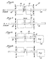
- Figure 1 is a side elevational view partly in section showing a total containment device in accordance with this invention as used in dialysis;
- Figure 2 is a top plan view of a portion of the device shown in Figure 1 with the upper clamp member removed;
- Figure 3 is a cross-sectional view taken through Figure 2 along the line 3-3;
- Figure 4 is a cross-sectional view taken through Figure 2 along the line 4-4;
- Figure 5 is a side elevational view of the holder used in the device used in Figures 1-4;
- Figure 6 is a schematic top plan view showing two tubes in a position to be welded or connected in accordance with this invention;
- Figure 7 is a view similar to Figure 6 showing the tubes welded together;
- Figure 8 is a view similar to Figures 6-7 showing a single tube in its position for being disconnected into two separate tube sections; and
- Figure 9 is a view similar to Figure 8 showing the two tube sections disconnected from each other.
- The present invention relates to refinements in the total containment devices described in the parent patents and applications, the details of which are incorporated herein with respect to each of the parent patents and applications. In general, the
device 10 includes a pair of side byside tube holders clamping tube sections flat seal 20 is formed which is generally horizontal in its wide dimension. The present invention is intended to assure that the proper orientation of the tube results in use of the total containment device. This means in having theseal 20 remain horizontal and in having the end of the tube extend outwardly from the tube holder by the desired distance. - The drawings illustrate the utilization of a
key member 22 which accomplishes this location and orientation feature. As shown in the drawings only onekey 22 is provided on one of thetube sections 16. If desired the invention may be practiced by having a key on theother tube section 18. The provision of asingle key 22, however, serves remarkably well for assuring proper orientation and spacing of the tube sections. - Figures 1-5 illustrate in more detail the
holder 12. As shown thereinholder 12 includes alower clamping member 24 and anupper clamping member 26 pivotally mounted thereto atpivot pin 28 so thatupper clamping member 26 may move toward and away fromlower clamping member 24 to clamp thetube section 16 in position.Handle 30 is utilized for manipulating theupper clamping member 26 in the manner described in the parent patents and applications. -
Lower clamping member 24 includes agroove 32 which extends completely longitudinally across thelower clamping member 24 so that itstube section 16 may be mounted in the groove and would be in alignment with thecorresponding tube section 18 located in a similar groove ofholder 14. - In accordance with this invention a
recess 34 is formed transversely acrossgroove 32 at a predetermined distance so that thekey 22 may be seated inrecess 34 and thereby locate the free end oftube section 16 the desired distance into the space betweentube holders recess 34 and the corresponding shape ofkey 22, rotation oftube section 16 ingroove 32 is prevented. This assures maintaining the weldedseal 20 in a horizontal orientation. - As illustrated in Figures 1-5 and in particular in Figures 2-3,
key 22 includes atube enclosing member 36 which has aninner wall 38 so that twotube portions tube enclosing member 36 until thetube portions wall 38.Tube portions tube enclosing member 36 by any suitable means such as the use of a cyclohexonone seal. This assures that there can be no relative sliding or rotational movement ofkey 22 with respect totube section 16. In the preferred practice of this invention thewall 38 has a circular opening with an inner surface of the same dimensions as and thus be flush with theinner surface 40 oftube section 16. This assures unimpeded flow through thetube section 16 even wherekey 22 is located. -
Key 22 also includes a flat elongatedtop wall 42 which extends outwardly fromtube enclosing member 36. The upper surface ofwall 42 is flat so as to be flush with theupper surface 44 oflower clamping member 24 as best shown in Figure 3. - Tube enclosing
member 36 may be of any shape but preferably includes flat surfaces to fit snugly against the corresponding flat surfaces inrecess 34 acrossgroove 32. - Figure 1 illustrates use of the invention for substituting a new dialysis bag for a used bag.
Bag 46 would contain a solution such as a dialysate which would be free to flow throughtube section 16. When it is intended to connecttube section 16 to atube 18 leading from a patient such as shown in Figures 6-7 it is first necessary to remove theseals 20 so that thetubes tube 16, aclamp 48 is applied a suitable distance from theseal 20. See Figure 1. In a practice of theinvention key 22 would be located 2.90 cm. from the distal end orseal 20 whileclamp 48 would also be located 2.90 cm. fromkey 22. - As shown in Figure 1 the solution or
fluid 49 frombag 46 thus can not pass throughclamp 48. Accordingly, adry chamber 50 is formed in the remaining portion oftube section 16 so as to prevent any fluid spillage whenseal 20 is broken. -
Key 22 may be made of any suitable material such as rigid PVC. The tubes may also be of any suitable material such as but not limited to conventional PVC tubing. - Figures 6-7 show use of the invention for connecting two
tube sections tube section appropriate holder moveable locating wall 51 is mounted atseal 20 onholder 14.Wall 51 functions as a stop wall to limit the extent to whichtube section 18 may extend beyond itstube holder 14. Aftertube section 18 is properly positioned inholder 14,wall 51 is removed from contact with theseal 20 at the end oftube section 18 so that eachseal 20 oftube sections - A heated wafer (not shown) would pass through the space between the two sealed ends 20,20 to melt the ends. In the next step of operation which is shown in Figure 7 the melted ends are fused together so that an integral tube results from
tube sections - Figures 8-9 illustrate the practice of the invention where an integral tube is disconnected to form two
separate sections side tube holders key 22 controlling the location of the tube in both of theholders bag 52 so that anew bag 46 could later be connected totube section 18 leading from the patient as previously described. - The advantages of the present invention include the ability to be able to accurately insert the tubing in the tube holder. Where only one key is used the key would be mounted on the tubing leading from the solution bag. The invention also permits precise square seals to be formed. The welded seals are particularly strong. The distal end is made from dry tubing by the utilization of the
clamp 48 as previously described.Clamp 48 would be removed after the connect operation is done. With the practice of the invention there is minimum tubing loss. The invention provides the ability to disconnect exactly at the previous weld because the key controls the location of the tubing. By disconnecting at the previous weld, the tubing loss might be only about 1.0 cm. per day or approximately 2.0 mm. per cycle from the patient's end otherwise the tubing loss would be 10 cm. per day. - By utilizing a key on the
tube section 16 there is assurance of having one tube section fixed in its location thus leaving only one variable to be verified for the connect procedure. The key also serves as a means for product identification to assure a user that the solution bag and its tubing are being provided from a proper supplier. - It should be noted that the objects and advantages of the invention may be attained by means of any compatible combination(s) particularly pointed out in the items of the following summary of the invention and the appended claims.
-
- 1. In a device for the sterile connect/disconnect of plastic tubing having a pair of side by side tube holders, each of said tube holders having a lower clamp member and an upper clamp member movably connected to said lower clamp member for selective movement toward and away from said lower clamp member to selectively clamp a tube section therebetween with the tube section in each of said holders aligned with each other and extending into a space between said holders, and means for heating the tubes in a space for selectively connecting the tube sections when the tube sections are initially separate from each other by welding the heated tube sections together and disconnecting the tube sections when the tube sections are initially joined together, the improvement being in that said lower clamp member of at least one of said holders has a groove longitudinally across its upper surface for locating its tube section on said lower clamp member, and a recess extending transversely outwardly from said groove to receive a key secured to the tube section for accurately locating the tube section in said lower clamp member.
- 2. The device wherein said recess extends completely across said groove on both sides of said groove.
- 3. The device in combination with a plastic tube section, said plastic tube section having a key fixed thereto, and said key being mounted in said recess.
- 4. The device wherein said tube section terminates in a flat seal, and said key locating said flat seal parallel to the upper surface of said lower clamp member.
- 5. The device wherein said tube section having said key is connected to a solution bag carrying a fluid therein, and a clamp member mounted to said tube section between said key and said solution bag for creating a dry chamber in said tube section between said clamp member and said seal.
- 6. The device wherein said key includes an upper wall flush with said upper surface of said lower clamp member.
- 7. The device wherein said key includes a tube enclosing member mounted around said tube section, and said upper wall of said key extending across and outwardly of said tube enclosing member.
- 8. The device wherein said tube enclosing member includes an inner wall having a circular opening therethrough, said tube section being formed from two separate tube portions, each of said tube portions being telescoped into said tube enclosing member and abutting against said inner wall with each of said tube portions being on an opposite side of said inner wall, and said tube portions having an inner surface flush with the inner surface formed by said circular opening in said inner wall to create an unobstructed flow path through said tube portions and said key.
- 9. The device wherein at least portions of said tube enclosing member fits snugly against and contacts said recess.
- 10. A tube assembly for use with a sterile connect/disconnect device comprising a hollow plastic tube having two ends, a key mounted to said tube inwardly of said ends, said key being fixedly mounted to prevent rotational and sliding movement of said key with respect to said tube, said key including a tube enclosing member around said tube, and a flat wall connected to said tube enclosing member and extending outwardly thereof.
- 11. The tube assembly wherein said key includes a tube enclosing member mounted around said tube section, and said upper wall of said key extending across and outwardly of said tube enclosing member.
- 12. The tube assembly wherein said tube enclosing member includes an inner wall having a circular opening therethrough, said tube section being formed from two separate tube portions, each of said tube portions being telescoped into said tube enclosing member and abutting against said inner wall with each of said tube portions being on an opposite side of said inner wall, and said tube portions having an inner surface flush with the inner surface formed by said circular opening in said inner wall to create an unobstructed flow path through said tube portions and said key.
- 13. The tube assembly wherein said tube section having said key is connected to a solution bag carrying a fluid therein, and a clamp member mounted to said tube section between said key and said solution bag for creating a dry chamber in said tube section between said clamp member and said seal.
- 14. The tube assembly wherein said end of said tube terminates in a flat seal parallel to said flat wall of said key.
- 15. In a method of sterile selective connecting and disconnecting of plastic tubing wherein a first tube section is mounted between upper and lower clamping members in a first holder located side by side and spaced from a second holder with a second tube section mounted between upper and lower clamping members of the second holder, the first and the second tube sections being aligned with each other and being selectively connected or disconnected with the aid of a heated wafer passing through the space between the holders, the improvement being in mounting a key to one of the tube sections, and disposing the key in a correspondingly shaped recess in the lower clamping member of one of the holders to fix the location of that tube section in the holder.
- 16. The method including mounting said key in said recess with the upper surface of the key being coplanar with the upper surface of the lower clamping member.
- 17. The method wherein the tube section is formed of two tube portions mounting the tube portions to the key by inserting each portion into a tube enclosing member of the key until the tube portion contacts an inner wall of the tube enclosing member, and sealing the tube portions to the key.
- 18. The method wherein the method is used for disconnecting a plastic tubing formed by welding the first and second tube sections together, and disconnecting the first and second tube sections from each other through the location of the weld.
- 19. The method wherein the tube section having the key is connected to a solution bag having fluid therein clamping a portion of the tube section at a location between the solution bag and the key to create a dry chamber within the tube section between the clamp and the sealed end of the tube section connecting the tube section to another tube section, and then removing the clamp.
Claims (10)
- In a device for the sterile connect/disconnect of plastic tubing having a pair of side by side tube holders, each of said tube holders having a lower clamp member and an upper clamp member movably connected to said lower clamp member for selective movement toward and away from said lower clamp member to selectively clamp a tube section therebetween with the tube section in each of said holders aligned with each other and extending into a space between said holders, and means for heating the tubes in a space for selectively connecting the tube sections when the tube sections are initially separate from each other by welding the heated tube sections together and disconnecting the tube sections when the tube sections are initially joined together, the improvement being in that said lower clamp member of at least one of said holders has a groove longitudinally across its upper surface for locating its tube section on said lower clamp member, and a recess extending transversely outwardly from said groove to receive a key secured to the tube section for accurately locating the tube section in said lower clamp member.
- The device of Claim 1 wherein said recess extends completely across said groove on both sides of said groove.
- The device of Claim 2 in combination with a plastic tube section, said plastic tube section having a key fixed thereto, and said key being mounted in said recess.
- The device of Claim 3 wherein said tube section terminates in a flat seal, and said key locating said flat seal parallel to the upper surface of said lower clamp member,wherein preferably said tube section having said key is connected to a solution bag carrying a fluid therein, and a clamp member mounted to said tube section between said key and said solution bag for creating a dry chamber in said tube section between said clamp member and said seal, andwherein preferably said key includes an upper wall flush with said upper surface of said lower clamp member.
- The device of any of claims 1-3 wherein said key includes a tube enclosing member mounted around said tube section, and said upper wall of said key extending across and outwardly of said tube enclosing member,wherein preferably said tube enclosing member includes an inner wall having a circular opening therethrough, said tube section being formed from two separate tube portions, each of said tube portions being telescoped into said tube enclosing member and abutting against said inner wall with each of said tube portions being on an opposite side of said inner wall, and said tube portions having an inner surface flush with the inner surface formed by said circular opening in said inner wall to create an unobstructed flow path through said tube portions and said key,wherein preferably at least portions of said tube enclosing member fits snugly against and contacts said recess.
- A tube assembly for use with a sterile connect/disconnect device comprising a hollow plastic tube having two ends, a key mounted to said tube inwardly of said ends, said key being fixedly mounted to prevent rotational and sliding movement of said key with respect to said tube, said key including a tube enclosing member around said tube, and a flat wall connected to said tube enclosing member and extending outwardly thereof.
- The tube assembly of Claim 6 wherein said key includes a tube enclosing member mounted around said tube section, and said upper wall of said key extending across and outwardly of said tube enclosing member,wherein preferably said tube enclosing member includes an inner wall having a circular opening therethrough, said tube section being formed from two separate tube portions, each of said tube portions being telescoped into said tube enclosing member and abutting against said inner wall with each of said tube portions being on an opposite side of said inner wall, and said tube portions having an inner surface flush with the inner surface formed by said circular opening in said inner wall to create an unobstructed flow path through said tube portions and said key,wherein preferably said tube section having said key is connected to a solution bag carrying a fluid therein, and a clamp member mounted to said tube section between said key and said solution bag for creating a dry chamber in said tube section between said clamp member and said seal ,andwherein preferably said end of said tube terminates in a flat seal parallel to said flat wall of said key.
- In a method of sterile selective connecting and disconnecting of plastic tubing wherein a first tube section is mounted between upper and lower clamping members in a first holder located side by side and spaced from a second holder with a second tube section mounted between upper and lower clamping members of the second holder, the first and the second tube sections being aligned with each other and being selectively connected or disconnected with the aid of a heated wafer passing through the space between the holders, the improvement being in mounting a key to one of the tube sections, and disposing the key in a correspondingly shaped recess in the lower clamping member of one of the holders to fix the location of that tube section in the holder.
- The method of Claim 8 including mounting said key in said recess with the upper surface of the key being coplanar with the upper surface of the lower clamping member,wherein preferably the tube section is formed of two tube portions mounting the tube portions to the key by inserting each portion into a tube enclosing member of the key until the tube portion contacts an inner wall of the tube enclosing member, and sealing the tube portions to the key,wherein the method is preferably used for disconnecting a plastic tubing formed by welding the first and second tube sections together, and disconnecting the first and second tube sections from each other through the location of the weld, andwherein preferably the tube section having the key is connected to a solution bag having fluid therein clamping a portion of the tube section at a location between the solution bag and the key to create a dry chamber within the tube section between the clamp and the sealed end of the tube section connecting the tube section to another tube section, and then removing the clamp.
- A device for the sterile connect/disconnect of plastic tubing having tube holders, each of said tube holders having a lower clamp member and an upper clamp member, wherein said lower clamp member of at least one of said holders has a groove for locating its tube section, and a recess to receive a key secured to the tube section for accurately locating the tube section in said lower clamp member.
Applications Claiming Priority (2)
| Application Number | Priority Date | Filing Date | Title |
|---|---|---|---|
| US37398195A | 1995-01-18 | 1995-01-18 | |
| US373981 | 1995-01-18 |
Publications (2)
| Publication Number | Publication Date |
|---|---|
| EP0723851A2 true EP0723851A2 (en) | 1996-07-31 |
| EP0723851A3 EP0723851A3 (en) | 1998-01-21 |
Family
ID=23474736
Family Applications (1)
| Application Number | Title | Priority Date | Filing Date |
|---|---|---|---|
| EP96100288A Withdrawn EP0723851A3 (en) | 1995-01-18 | 1996-01-10 | Total containment connect/disconnect device |
Country Status (3)
| Country | Link |
|---|---|
| EP (1) | EP0723851A3 (en) |
| JP (1) | JPH08309862A (en) |
| CA (1) | CA2164749A1 (en) |
Cited By (10)
| Publication number | Priority date | Publication date | Assignee | Title |
|---|---|---|---|---|
| WO2008005882A2 (en) * | 2006-07-07 | 2008-01-10 | Caridianbct, Inc. | Heat weld tube connectors |
| US7722733B2 (en) | 2004-03-29 | 2010-05-25 | Baxter International Inc. | Method for sterile connection of tubing |
| US8146642B2 (en) | 2002-01-31 | 2012-04-03 | Baxter International Inc. | Apparatus and method for connecting and disconnecting flexible tubing |
| WO2015060774A1 (en) | 2013-10-24 | 2015-04-30 | Ge Healthcare Bio-Sciences Ab | Apparatus for connection of thermoplastic tubing |
| US9199070B2 (en) | 2011-12-21 | 2015-12-01 | Fenwal, Inc. | Fluid flow conduits and apparatus and methods for making and joining fluid conduits |
| US9308709B2 (en) | 2013-06-06 | 2016-04-12 | Fenwal, Inc. | Bonding apparatus and method |
| US9440396B2 (en) | 2014-06-19 | 2016-09-13 | Fenwal, Inc. | Sterile connection device for making multiple connections |
| US9533135B2 (en) | 2014-06-19 | 2017-01-03 | Fenwal, Inc. | Method for forming, opening and/or evaluating a connection site |
| US10040247B2 (en) | 2010-08-18 | 2018-08-07 | Fresenius Kabi Deutschland Gmbh | Method for the sterile connection of pipes |
| US10919235B2 (en) | 2017-06-07 | 2021-02-16 | Fenwal, Inc. | Apparatus and method for mechanically opening a connection site |
Citations (8)
| Publication number | Priority date | Publication date | Assignee | Title |
|---|---|---|---|---|
| GB2134202A (en) * | 1983-01-18 | 1984-08-08 | Travenol Europ Res & Dev | Connection device |
| WO1985000979A1 (en) * | 1983-08-19 | 1985-03-14 | Baxter Travenol Laboratories, Inc. | Device for providing antibacterial radiation |
| JPS60198227A (en) * | 1984-03-22 | 1985-10-07 | Sekisui Chem Co Ltd | Preparation of thermoplastic resin tube with node |
| US4655753A (en) * | 1985-11-27 | 1987-04-07 | Baxter Travenol Laboratories, Inc. | Connection device |
| DE9001311U1 (en) * | 1989-02-09 | 1990-04-12 | Georg Fischer Ag, Schaffhausen, Ch, Niederlassung: Georg Fischer Ag, 7700 Singen, De | |
| EP0459600A1 (en) * | 1988-04-29 | 1991-12-04 | Baxter International Inc. | Apparatus for exchanging and irradiating tubing connections |
| US5279685A (en) * | 1990-08-20 | 1994-01-18 | Denco, Inc. | Total containment device for connect/disconnect of plastic tubes |
| EP0619175A2 (en) * | 1993-03-11 | 1994-10-12 | Denco, Inc. | Sterile containment welding device for plastic tubes |
-
1995
- 1995-12-08 CA CA002164749A patent/CA2164749A1/en not_active Abandoned
-
1996
- 1996-01-10 JP JP8002293A patent/JPH08309862A/en active Pending
- 1996-01-10 EP EP96100288A patent/EP0723851A3/en not_active Withdrawn
Patent Citations (8)
| Publication number | Priority date | Publication date | Assignee | Title |
|---|---|---|---|---|
| GB2134202A (en) * | 1983-01-18 | 1984-08-08 | Travenol Europ Res & Dev | Connection device |
| WO1985000979A1 (en) * | 1983-08-19 | 1985-03-14 | Baxter Travenol Laboratories, Inc. | Device for providing antibacterial radiation |
| JPS60198227A (en) * | 1984-03-22 | 1985-10-07 | Sekisui Chem Co Ltd | Preparation of thermoplastic resin tube with node |
| US4655753A (en) * | 1985-11-27 | 1987-04-07 | Baxter Travenol Laboratories, Inc. | Connection device |
| EP0459600A1 (en) * | 1988-04-29 | 1991-12-04 | Baxter International Inc. | Apparatus for exchanging and irradiating tubing connections |
| DE9001311U1 (en) * | 1989-02-09 | 1990-04-12 | Georg Fischer Ag, Schaffhausen, Ch, Niederlassung: Georg Fischer Ag, 7700 Singen, De | |
| US5279685A (en) * | 1990-08-20 | 1994-01-18 | Denco, Inc. | Total containment device for connect/disconnect of plastic tubes |
| EP0619175A2 (en) * | 1993-03-11 | 1994-10-12 | Denco, Inc. | Sterile containment welding device for plastic tubes |
Non-Patent Citations (1)
| Title |
|---|
| PATENT ABSTRACTS OF JAPAN vol. 010, no. 047 (M-456), 25 February 1986 & JP 60 198227 A (SEKISUI KAGAKU KOGYO KK), 7 October 1985, * |
Cited By (18)
| Publication number | Priority date | Publication date | Assignee | Title |
|---|---|---|---|---|
| US8146642B2 (en) | 2002-01-31 | 2012-04-03 | Baxter International Inc. | Apparatus and method for connecting and disconnecting flexible tubing |
| US7722733B2 (en) | 2004-03-29 | 2010-05-25 | Baxter International Inc. | Method for sterile connection of tubing |
| WO2008005882A3 (en) * | 2006-07-07 | 2008-03-27 | Gambro Bct Inc | Heat weld tube connectors |
| US7964048B2 (en) | 2006-07-07 | 2011-06-21 | Caridianbct, Inc. | Heat weld tubing connectors |
| WO2008005882A2 (en) * | 2006-07-07 | 2008-01-10 | Caridianbct, Inc. | Heat weld tube connectors |
| US10040247B2 (en) | 2010-08-18 | 2018-08-07 | Fresenius Kabi Deutschland Gmbh | Method for the sterile connection of pipes |
| US11351742B2 (en) | 2010-08-18 | 2022-06-07 | Fresenius Kabi Deutschland Gmbh | Method and device for the sterile connection of pipes |
| US10569478B2 (en) | 2010-08-18 | 2020-02-25 | Fresenius Kabi Deutschland Gmbh | Method and device for the sterile connection of pipes |
| US10549484B2 (en) | 2010-08-18 | 2020-02-04 | Fresenius Kabi Deutschland Gmbh | Method and device for the sterile connection of pipes |
| US10307582B2 (en) | 2011-12-21 | 2019-06-04 | Fenwal, Inc. | Fluid flow conduits and apparatus and methods for making and joining fluid conduits |
| US9199070B2 (en) | 2011-12-21 | 2015-12-01 | Fenwal, Inc. | Fluid flow conduits and apparatus and methods for making and joining fluid conduits |
| US9308709B2 (en) | 2013-06-06 | 2016-04-12 | Fenwal, Inc. | Bonding apparatus and method |
| WO2015060774A1 (en) | 2013-10-24 | 2015-04-30 | Ge Healthcare Bio-Sciences Ab | Apparatus for connection of thermoplastic tubing |
| US9533135B2 (en) | 2014-06-19 | 2017-01-03 | Fenwal, Inc. | Method for forming, opening and/or evaluating a connection site |
| US10143829B2 (en) | 2014-06-19 | 2018-12-04 | Fenwal, Inc. | Apparatus and method for opening and/or evaluating connection site |
| US9440396B2 (en) | 2014-06-19 | 2016-09-13 | Fenwal, Inc. | Sterile connection device for making multiple connections |
| US10919235B2 (en) | 2017-06-07 | 2021-02-16 | Fenwal, Inc. | Apparatus and method for mechanically opening a connection site |
| US11325321B2 (en) | 2017-06-07 | 2022-05-10 | Fenwal, Inc. | Apparatus and method for mechanically opening a connection site |
Also Published As
| Publication number | Publication date |
|---|---|
| EP0723851A3 (en) | 1998-01-21 |
| JPH08309862A (en) | 1996-11-26 |
| CA2164749A1 (en) | 1996-07-19 |
Similar Documents
| Publication | Publication Date | Title |
|---|---|---|
| EP0649727B1 (en) | Total containment welding of plastic tubes | |
| US4897138A (en) | Sealing of plastic tubes | |
| US4737214A (en) | Method for providing sterile connection of plastic tubes or the like | |
| EP0589587B1 (en) | Improved radio frequency tubing sealer | |
| EP0508373B1 (en) | Total containment welding of plastic tubes | |
| EP0507321B1 (en) | Method and apparatus for joining tubes | |
| CA1204566A (en) | Sterile docking process, apparatus and system | |
| US4913756A (en) | Techniques for welding thermoplastic tubes | |
| EP0104718B1 (en) | Sterile docking process, apparatus and system for thermoplastic resin tubes | |
| CA1204567A (en) | Sterile docking process, apparatus and system | |
| US5397425A (en) | Total containment welding of plastic tubes | |
| EP0723851A2 (en) | Total containment connect/disconnect device | |
| EP1238782A1 (en) | Total containment welding of plastic tubes | |
| US4832773A (en) | Techniques for welding thermoplastic tubes | |
| US4770735A (en) | Techniques for welding thermoplastic tubes | |
| EP0903214B1 (en) | Sterile containment welding device for plastic tubes | |
| IE860621L (en) | Sterile, cold cut connection of thermoplestic tubes | |
| EP0619175A2 (en) | Sterile containment welding device for plastic tubes | |
| JP3043895B2 (en) | Aseptic welding method for plastic tube section | |
| JP2710038B2 (en) | Tube aseptic connection method and device | |
| EP0852180B1 (en) | Medical device having a branch and process for producing the same | |
| EP0015897B1 (en) | Method of joining conduits with a connecting piece and connecting piece for carrying out the method | |
| US4303458A (en) | Method of joining conduits with a connecting piece and connecting piece for use in the method | |
| CA1174419A (en) | Sterile docking process, apparatus and system | |
| JPH09300467A (en) | Butt welding machine |
Legal Events
| Date | Code | Title | Description |
|---|---|---|---|
| PUAI | Public reference made under article 153(3) epc to a published international application that has entered the european phase |
Free format text: ORIGINAL CODE: 0009012 |
|
| AK | Designated contracting states |
Kind code of ref document: A2 Designated state(s): AT BE CH DE DK ES FR GB GR IE IT LI LU MC NL PT SE |
|
| PUAL | Search report despatched |
Free format text: ORIGINAL CODE: 0009013 |
|
| AK | Designated contracting states |
Kind code of ref document: A3 Designated state(s): AT BE CH DE DK ES FR GB GR IE IT LI LU MC NL PT SE |
|
| RHK1 | Main classification (correction) |
Ipc: B29C 65/78 |
|
| STAA | Information on the status of an ep patent application or granted ep patent |
Free format text: STATUS: THE APPLICATION IS DEEMED TO BE WITHDRAWN |
|
| 18D | Application deemed to be withdrawn |
Effective date: 19980722 |