EP0727285A1 - Fastening tool with a piston driven by compressed gas - Google Patents
Fastening tool with a piston driven by compressed gas Download PDFInfo
- Publication number
- EP0727285A1 EP0727285A1 EP96400055A EP96400055A EP0727285A1 EP 0727285 A1 EP0727285 A1 EP 0727285A1 EP 96400055 A EP96400055 A EP 96400055A EP 96400055 A EP96400055 A EP 96400055A EP 0727285 A1 EP0727285 A1 EP 0727285A1
- Authority
- EP
- European Patent Office
- Prior art keywords
- cylinder
- sleeve
- piston
- chamber
- feeler
- Prior art date
- Legal status (The legal status is an assumption and is not a legal conclusion. Google has not performed a legal analysis and makes no representation as to the accuracy of the status listed.)
- Granted
Links
Images


Classifications
-
- B—PERFORMING OPERATIONS; TRANSPORTING
- B25—HAND TOOLS; PORTABLE POWER-DRIVEN TOOLS; MANIPULATORS
- B25C—HAND-HELD NAILING OR STAPLING TOOLS; MANUALLY OPERATED PORTABLE STAPLING TOOLS
- B25C1/00—Hand-held nailing tools; Nail feeding devices
- B25C1/08—Hand-held nailing tools; Nail feeding devices operated by combustion pressure
Definitions
- the present invention relates to a buffer sealing apparatus by a piston propelled by compressed gas, comprising a buffer guide, a cylinder in which the piston is mounted, a combustion chamber sleeve mounted slidingly for, during support of the device, close the chamber, at the rear, with a cylinder head carrying ignition means and, at the front, with the piston and the cylinder, a gas reserve, gas injection means in the chamber and a feeler for resting and closing the chamber.
- Apparatuses of this type intended for fixing, for example, wood or strips on steel or concrete, offer the advantage of great autonomy, thanks to the capacity of the gas reserve cartridges with which they are equipped. With a single cartridge, you can fire about a thousand shots. However, these devices have the drawback of a relatively limited power, in particular because of the too low calorific power of the gas.
- the apparatus of the present invention is characterized in that the cylinder is mounted movable in translation in a housing of the apparatus, the buffer guide performs a probe function and it is integral in translation with the cylinder and there are provided means for retaining the piston in the cylinder.
- the Applicant has therefore transformed the appliance of US-A-4 403 722 into a more powerful appliance, the volume of the combustion chamber of which, after it has been closed, can be reduced.
- the cylinder can be secured to an anterior skirt slidingly mounted on the rear housing.
- the housing extends axially along the entire sleeve and the entire cylinder.
- means are provided which are arranged to drive the sleeve backwards under the action of the translational displacement of the bearing of the cylinder.
- the action of the means for driving the sleeve towards the rear is exerted against the action of means for returning the cylinder towards the front of the housing of the device.
- the means for driving the sleeve towards the rear comprise at least one lever pivotally mounted on the cylinder against the action of a spring secured, by its ends, to the lever and to the housing of the device.
- the cylinder is slidably mounted in the sleeve which has a groove open towards the front, in which extends a lug secured to the cylinder, intended to come into abutment against the rear bottom of the groove only after closing of bedroom.
- the cylinder is slidably mounted in the sleeve towards the front under the action of the return means to open the chamber at the front before it opens at the rear by disengaging the sleeve from the cylinder head. .
- the internal bore of the cylinder for receiving the piston can be widened towards the rear and form a ramp and the piston comprise a peripheral annular groove of retention in which is disposed a retention segment. arranged for cooperate with the ramp and retain the piston when the cylinder recedes after closing the chamber.
- the piston comprises, in front of the retaining groove, an annular peripheral sealing groove in which is disposed a sealing segment arranged to cooperate with the wall of the internal bore of the cylinder.
- the apparatus of the type mentioned above can therefore also, in the context of the present invention, be improved and have a combustion chamber with reducible volume thanks to the fact that, the probe being integral in translation with the sleeve, the cylinder is mounted movable in translation in a housing of the device, the feeler function during resting is ensured successively by the feeler secured to the sleeve then by the buffer guide and means are provided for retaining the piston in the cylinder .
- the feeler secured to the sleeve includes means arranged so as not to hinder the feeler function of the buffer guide.
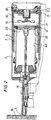
- the apparatus essentially comprises, in a housing 1, a cylinder head 2, a cylinder 3, a sleeve 4, a buffer guide 5, partly projecting from the housing, and a piston 6 for propelling the buffer, all of these elements , of axis 7.
- the piston 6 is slidably mounted in the cylinder 3 which is slidably mounted in the sleeve 4 which is itself slidably mounted in the housing 1.
- the relative sliding of the cylinder 3 and of the sleeve 4 is however limited, as we will see later.
- the buffer guide 5 is screwed onto the cylinder 3.
- the sleeve 4 comprises at the rear a neck 8 which can abut against a corresponding zone 9 of the cylinder head, to close, at the rear, a combustion chamber 10.
- the sleeve 4 also comprises, substantially in part median, an internal annular surface 11 intended to receive a seal 12 carried in an annular groove at the rear of the cylinder 3, to close, at the front, the combustion chamber 10.
- a spark plug 13 and a mixing fan 14 are carried by the cylinder head 2.
- the apparatus When a tampon 15 is put in place in the tampon guide 5, the apparatus is pressed against the material 16 intended to receive the tampon 15. The tampon guide 5 then acts as a feeler.
- An injection pipe 17 is formed through the cylinder head 2, opening into the combustion chamber 10, for the arrival of the propellant gas from a cartridge and a metering device, not shown.
- the cylinder head 2 carries a switch 18 intended to be actuated by the rear part of the sleeve 4, adjacent to its neck 8, when this neck comes into abutment against the zone 9 for closing the chamber of the cylinder head.
- a cylinder return cup 19, open towards the rear, is here screwed, by its bottom 20, to the housing 1. It is extended, towards the rear, by two rods 21 diametrically opposite and parallel to the axis 7, at the free end of which is fixed one end of a return spring 22.
- the other end of the springs 22 is fixed to a lever 23 pivotally mounted on a lug 24 driven substantially radially into the cylinder 3.
- the end of each lever 23, opposite to that to which a spring 22 is fixed, carries a free support roller 25.
- the sleeve 4 has two large lateral notches 26, around the levers 23, with a rear bottom 27, in a transverse plane, against which a roller 25 is in abutment.
- the sleeve 4 also comprises, formed from its front edge, a groove 28, parallel to the axis 7, therefore open towards the front and into which is introduced a lug 29 screwed into the cylinder 3 and intended to come into abutment against the bottom of the groove when resting, to limit sliding towards the rear of the cylinder 3 after abutment of the sleeve 4 against the cylinder head 2.
- the sleeve 4 also includes a closed lumen 30, parallel to the axis 7, into which is introduced another screw 31 screwed into the cylinder 3 and intended to cooperate with the anterior bottom of the lumen when the apparatus opens, at the support outlet, for driving the sleeve 4 by the cylinder 3.
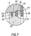
- the rear of the cylinder 3 has an annular recess in which are housed a piston retaining ring 32 and a piston stop ring 33.
- the first is to temporarily prevent the relative sliding forward of the piston in the cylinder and the second, to prevent the piston from coming out of the cylinder backwards.
- the ring 32 has a rear internal portion of enlarged diameter 45 which is connected to the front portion, substantially of the same diameter as the piston head 35, by a frustoconical ramp surface 34.
- the piston 6 comprises an enlarged rear head 35 in which two peripheral annular grooves 36, 37 are formed, the first, anterior, receiving a sealing segment 38 and, the second, posterior, a retention segment 39. In the resting state, the retention segment 39 projects out from his throat.
- the tampon guide 5 When the apparatus is pressed against the material 16 intended to receive a tampon 15, the tampon guide 5, as a feeler, drives the cylinder 3 backwards, in the housing 1 and, by intermediate of the levers 23 and notches 26, the sleeve 4 until the latter comes to bear, by its neck 8, against the zone 9 of the cylinder head 2 and closes the rear of the combustion chamber 10 (FIG. 2) .
- the gas cartridge released a dose of gas into the combustion chamber 10.
- the fan 14 is started to stir the air-gas mixture and the gasket 12 of the cylinder 3 is located just in front of the annular surface 11 of the sleeve, the combustion chamber is closed at the front by the gasket contact 12 of the cylinder 3 - surface 11 of the sleeve 4 and the segment contact d seal 38 of the piston 35 - internal bore 40 of the cylinder 3.
- the operator After closing the chamber 10, and continuing to press the device against the material 16, the operator will reduce the volume of the chamber to further compress the propellant gas.
- the sleeve 4 being immobilized against the cylinder head 2, the buffer guide 5 continues to roll back the cylinder 3 until the lug 29 integral with the cylinder 3 abuts against the rear bottom 41 of the groove 28 of the sleeve 4 (figure 3).
- the seal 12 of the cylinder has slid against the surface 11 of the sleeve to be at the rear of the latter, and to reduce by as much the volume of the chamber 10.
- the piston 35 remained integral in sliding of the cylinder 3 thanks to the retention of the retention segment 39 by the ramp 34 of the ring 32.
- the shot takes place when the candle 13 ignites.
- a spark causes the explosion which creates a pressure greater than the force of the retention segment 39.
- the latter retracts into its groove 37 by sliding on the ramp 34 and the piston 35 thus escapes from the retention ring 32.
- the segment 39 behaves like a conventional segment.
- the piston rod 6 strikes the buffer 15 which is fixed in the material 16. The piston continues its stroke until its head 35 comes against the damper 42.
- the combustion chamber 10 Immediately after the start of the driving of the sleeve 4 by the cylinder 3, the combustion chamber 10 also opens at the rear, by clearing the neck 8 from the zone 9 of the cylinder head 2, and the fan 14 sucks in fresh air through the lights in the cylinder head.
- the lug 29 makes it possible to adjust the compression ratio and that if this ratio does not have to be modified, other even simpler means can be provided for limiting the sliding of the cylinder towards the rear.
- the relative dimensions of the piston head 35, of the retention ring 32 and of its ramp 34 are adapted to the desired retention force.
- the ring 32 should be considered as a wearing part; the cylinder 3 and the rings 32, 33 could be one piece.
- the apparatus of the invention is not fundamentally different from that of Figures 1-7. It is essentially distinguished from it by the fact that it is a little closer to the starting device of document US-A-4 403 722, the probe remaining integral with the sleeve.
- the apparatus of these last three figures comprises a buffer guide 50, a cylinder 51, in which is mounted a piston with retention means in the cylinder, a sleeve 52 of combustion chamber 53, a cylinder head 54, a reserve of gas, means for injecting the gas into the chamber and a feeler 55.
- the feeler 55 is integral in translation with the sleeve 52.
- the sleeve 52 is slidably mounted in the housing 56, against return means 57.
- the cylinder 51 is mounted movable in translation relative to the sleeve 52, against return means 58.
- the feeler 55 begins by pushing the sleeve 52 backwards to close the chamber 53 with the breech 54 at the rear.
- the buffer guide 50 comes into contact with the material -support 61 against which the device is pressed, the buffer guide 50 thus performs a probe function to drive the cylinder 51 and the piston 59 backwards and finish closing the chamber 53 at the front, with the piston 59 and the cylinder 51 (FIG. 8B).
- the buffer guide 50 continues to drive the cylinder 51 and the piston 59 backwards in the sleeve 52, to reduce the volume of the chamber 53 (FIG. 8C).
- the probe 55 itself must not cause this function. This is why the probe 55 includes means intended for this. In this case, it comprises a compressible intermediate spring 60. But it could also have a telescopic part.
Abstract
Description
La présente invention concerne un appareil de scellement de tampon par un piston propulsé par gaz comprimé, comprenant un guide-tampon, un cylindre, dans lequel est monté le piston, un manchon de chambre de combustion monté coulissant pour, lors d'une mise en appui de l'appareil, fermer la chambre, à l'arrière, avec une culasse portant des moyens d'allumage et, à l'avant, avec le piston et le cylindre, une réserve de gaz, des moyens d'injection du gaz dans la chambre et un palpeur de mise en appui et de fermeture de chambre.The present invention relates to a buffer sealing apparatus by a piston propelled by compressed gas, comprising a buffer guide, a cylinder in which the piston is mounted, a combustion chamber sleeve mounted slidingly for, during support of the device, close the chamber, at the rear, with a cylinder head carrying ignition means and, at the front, with the piston and the cylinder, a gas reserve, gas injection means in the chamber and a feeler for resting and closing the chamber.
Les appareils de ce type, destinés à fixer par exemple du bois ou des feuillards sur de l'acier ou du béton, offrent l'avantage d'une grande autonomie, grâce à la capacité des cartouches-réserves de gaz dont ils sont équipés. Avec une seule cartouche, on peut tirer environ mille coups. Toutefois, ces appareils présentent l'inconvénient d'une puissance relativement limitée à cause notamment du trop faible pouvoir calorifique du gaz.Apparatuses of this type, intended for fixing, for example, wood or strips on steel or concrete, offer the advantage of great autonomy, thanks to the capacity of the gas reserve cartridges with which they are equipped. With a single cartridge, you can fire about a thousand shots. However, these devices have the drawback of a relatively limited power, in particular because of the too low calorific power of the gas.
La demanderesse a donc voulu augmenter la puissance des appareils du type rappelé ci-dessus en proposant une solution appropriée au problème de la compression du gaz après fermeture de la chambre de combustion et ce, parfaitement indépendemment de l'enseignement de US-A-4 712 379 qui n'a rien à voir avec celui de US-A-4 403 722.The Applicant therefore wanted to increase the power of the devices of the type mentioned above by proposing an appropriate solution to the problem of compression of the gas after closing the combustion chamber, and this, perfectly independently of the teaching of US-A-4 712,379 which has nothing to do with that of US-A-4,403,722.
L'appareil de la présente invention est caractérisé par le fait que le cylindre est monté mobile en translation dans un boîtier de l'appareil, le guide-tampon assure une fonction de palpeur et il est solidaire en translation du cylindre et il est prévu des moyens de rétention du piston dans le cylindre.The apparatus of the present invention is characterized in that the cylinder is mounted movable in translation in a housing of the apparatus, the buffer guide performs a probe function and it is integral in translation with the cylinder and there are provided means for retaining the piston in the cylinder.
Grâce à la mobilité du cylindre dans le boîtier de l'appareil, la demanderesse a donc transformé l'appareil de US-A-4 403 722 en un appareil plus puissant, dont le volume de la chambre de combustion, après sa fermeture, peut être réduit.Thanks to the mobility of the cylinder in the housing of the appliance, the Applicant has therefore transformed the appliance of US-A-4 403 722 into a more powerful appliance, the volume of the combustion chamber of which, after it has been closed, can be reduced.
Le cylindre peut être solidaire d'une jupe antérieure montée coulissante sur le boîtier postérieur.The cylinder can be secured to an anterior skirt slidingly mounted on the rear housing.
Mais dans la forme de réalisation préférée de l'appareil de l'invention, le boîtier s'étend axialement le long de tout le manchon et de tout le cylindre.But in the preferred embodiment of the apparatus of the invention, the housing extends axially along the entire sleeve and the entire cylinder.
Avantageusement, il est prévu des moyens agencés pour entraîner le manchon vers l'arrière sous l'action du déplacement en translation de mise en appui du cylindre.Advantageously, means are provided which are arranged to drive the sleeve backwards under the action of the translational displacement of the bearing of the cylinder.
Avantageusement, l'action des moyens d'entraînement du manchon vers l'arrière s'exercent contre l'action de moyens de rappel du cylindre vers l'avant du boîtier de l'appareil.Advantageously, the action of the means for driving the sleeve towards the rear is exerted against the action of means for returning the cylinder towards the front of the housing of the device.
Avantageusement encore, les moyens d'entraînement du manchon vers l'arrière comprennent au moins un levier monté pivotant sur le cylindre contre l'action d'un ressort solidaire, par ses extrémités, du levier et du boîtier de l'appareil.Advantageously also, the means for driving the sleeve towards the rear comprise at least one lever pivotally mounted on the cylinder against the action of a spring secured, by its ends, to the lever and to the housing of the device.
Avantageusement toujours, le cylindre est monté coulissant dans le manchon qui comporte une rainure ouverte vers l'avant, dans laquelle s'étend un ergot solidaire du cylindre, destiné à ne venir en butée contre le fond arrière de la rainure qu'après fermeture de la chambre.Still advantageously, the cylinder is slidably mounted in the sleeve which has a groove open towards the front, in which extends a lug secured to the cylinder, intended to come into abutment against the rear bottom of the groove only after closing of bedroom.
De préférence, le cylindre est monté coulissant dans le manchon vers l'avant sous l'action des moyens de rappel pour ouvrir le chambre à l'avant avant qu'elle ne s'ouvre à l'arrière par dégagement du manchon de la culasse.Preferably, the cylinder is slidably mounted in the sleeve towards the front under the action of the return means to open the chamber at the front before it opens at the rear by disengaging the sleeve from the cylinder head. .
Grâce à cela, un ventilateur, mis en manche par mise en butée du manchon contre la culasse, lors de la mise en appui de l'appareil, et donc toujours en marche à l'ouverture avant de la chambre, peut y aspirer de l'air frais.Thanks to this, a fan, put in the sleeve by abutment of the sleeve against the cylinder head, when the device is supported, and therefore always running at the front opening of the chamber, can suck in it. 'fresh air.
Pour constituer les moyens de rétention du piston dans le cylindre, l'alésage interne du cylindre de réception du piston peut être élargi vers l'arrière et former rampe et le piston comporter une gorge annulaire périphérique de rétention dans laquelle est disposé un segment de rétention agencé pour coopérer avec la rampe et retenir le piston lors du recul du cylindre après fermeture de la chambre.To constitute the means of retention of the piston in the cylinder, the internal bore of the cylinder for receiving the piston can be widened towards the rear and form a ramp and the piston comprise a peripheral annular groove of retention in which is disposed a retention segment. arranged for cooperate with the ramp and retain the piston when the cylinder recedes after closing the chamber.
De préférence, le piston comporte, en avant de la gorge de rétention, une gorge annulaire périphérique d'étanchéité dans laquelle est disposé un segment d'étanchéité agencé pour coopérer avec la paroi de l'alésage interne du cylindre.Preferably, the piston comprises, in front of the retaining groove, an annular peripheral sealing groove in which is disposed a sealing segment arranged to cooperate with the wall of the internal bore of the cylinder.
L'appareil de US-A-4 403 722, dont on a rendu le cylindre mobile dans le boîtier, comporte donc une chambre de combustion à volume pouvant être réduit pour rendre l'appareil plus puissant.The apparatus of US-A-4 403 722, the cylinder of which has been made mobile in the housing, therefore comprises a combustion chamber with a volume which can be reduced to make the apparatus more powerful.
A partir du même appareil de US-A-4 403 722, le même problème de l'augmentation de puissance peut être résolu d'une manière légèrement différente de celle revendiquée précédemment.From the same apparatus of US-A-4 403 722, the same problem of the increase in power can be solved in a slightly different way from that claimed previously.
L'appareil du type mentionné ci-dessus peut donc aussi, dans le cadre de la présente invention, être perfectionné et avoir une chambre de combustion à volume réductible grâce au fait que, le palpeur étant solidaire en translation du manchon, le cylindre est monté mobile en translation dans un boîtier de l'appareil, la fonction de palpeur lors de la mise en appui, est assurée successivement par le palpeur solidaire du manchon puis par le guide-tampon et il est prévu des moyens de retention du piston dans le cylindre.The apparatus of the type mentioned above can therefore also, in the context of the present invention, be improved and have a combustion chamber with reducible volume thanks to the fact that, the probe being integral in translation with the sleeve, the cylinder is mounted movable in translation in a housing of the device, the feeler function during resting is ensured successively by the feeler secured to the sleeve then by the buffer guide and means are provided for retaining the piston in the cylinder .
De préférence, dans ce cas, le palpeur solidaire du manchon comportent des moyens agencés pour ne pas entraver la fonction de palpeur du guide-tampon.Preferably, in this case, the feeler secured to the sleeve includes means arranged so as not to hinder the feeler function of the buffer guide.
L'invention sera mieux comprise à l'aide de la description de la forme de réalisation préférée de l'appareil de l'invention, en référence au dessin annexé, sur lequel
- la figure 1 est une vue en coupe axiale d'une première forme de réalisation de l'appareil, chambre de combustion ouverte ;
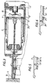
- la figure 2 est une vue analogue à la figure 1, chambre de combustion fermée ;
- la figure 3 est une vue analogue à la figure 2, en fin de mise en appui, chambre de combustion toujours fermée et à volume réduit ;
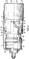
- la figure 4 est une vue latérale de l'ensemble cylindre-manchon de l'appareil des figures 1 à 3, partiellement en coupe ;
- la figure 5 est une vue à plus grande échelle, en coupe, du mécanisme d'entraînement vers l'avant du manchon par le cylindre de l'appareil des figures 1 à 4;
- la figure 6 est une vue à plus grande échelle, en coupe, du mécanisme d'arrêt du recul du cylindre de l'appareil des figures 1 à 5;
- la figure 7 est une vue à plus grande échelle, en coupe, de la portion arrière du cylindre, en position de fermeture de la chambre de combustion de l'appareil des figures 1 à 6;
- les figures 8A, 8B, 8C illustrent schématiquement le fonctionnement d'une deuxième forme de réalisation de l'appareil de l'invention.
- Figure 1 is an axial sectional view of a first embodiment of the apparatus, open combustion chamber;
- Figure 2 is a view similar to Figure 1, closed combustion chamber;
- Figure 3 is a view similar to Figure 2, at the end of support, combustion chamber still closed and reduced volume;
- Figure 4 is a side view of the cylinder-sleeve assembly of the apparatus of Figures 1 to 3, partially in section;
- Figure 5 is an enlarged view, in section, of the drive mechanism towards the front of the sleeve by the cylinder of the apparatus of Figures 1 to 4;
- Figure 6 is an enlarged view, in section, of the recoil stop mechanism of the cylinder of the apparatus of Figures 1 to 5;
- Figure 7 is an enlarged view, in section, of the rear portion of the cylinder, in the closed position of the combustion chamber of the apparatus of Figures 1 to 6;
- Figures 8A, 8B, 8C schematically illustrate the operation of a second embodiment of the apparatus of the invention.
L'appareil représenté sur les figures ne sera décrit que par ses seuls éléments qui le distinguent de celui de US-A-4 403 722 ainsi que naturellement par ses éléments nécessaires à la compréhension de l'invention.The device shown in the figures will only be described by its only elements which distinguish it from that of US-A-4 403 722 as well as naturally by its elements necessary for understanding the invention.
L'appareil comporte, essentiellement, dans un boîtier 1, une culasse 2, un cylindre 3, un manchon 4, un guide-tampon 5, en partie en saillie hors du boîtier, et un piston 6 de propulsion de tampon, tous ces éléments, d'axe 7. Le piston 6 est monté coulissant dans le cylindre 3 qui est monté coulissant dans le manchon 4 qui est lui-même monté coulissant dans le boîtier 1. Le coulissement relatif du cylindre 3 et du manchon 4 est toutefois limité, comme on le verra plus loin. Le guide-tampon 5 est vissé sur le cylindre 3.The apparatus essentially comprises, in a housing 1, a
Le manchon 4 comporte à l'arrière un col 8 pouvant venir en butée contre une zone correspondante 9 de la culasse, pour fermer, à l'arrière, une chambre de combustion 10. Le manchon 4 comporte aussi, sensiblement en partie médiane, une surface annulaire interne 11 destinée à recevoir un joint 12 porté dans une gorge annulaire à l'arrière du cylindre 3, pour fermer, à l'avant, la chambre de combustion 10.The
Une bougie d'allumage 13 et un ventilateur de mélange 14 sont portés par la culasse 2.A spark plug 13 and a
Quand un tampon 15 est mis en place dans le guide-tampon 5, on met l'appareil en appui contre le matériau 16 destiné à recevoir le tampon 15. Le guide-tampon 5 fait alors fonction de palpeur.When a
Un conduit d'injection 17 est ménagé à travers la culasse 2, débouchant dans la chambre de combustion 10, pour l'arrivée du gaz de propulsion depuis une cartouche et un doseur, non représentés.An
La culasse 2 porte un interrupteur 18 destiné à être actionné par la partie arrière du manchon 4, adjacente à son col 8, lorsque ce col vient en butée contre la zone 9 de fermeture de chambre de la culasse.The
Une coupelle 19 de rappel de cylindre, ouverte vers l'arrière, est ici vissée, par son fond 20, au boîtier 1. Elle se prolonge, vers l'arrière, par deux tiges 21 diamétralement opposées et parallèles à l'axe 7, à l'extrémité libre desquelles est fixée une extrémité d'un ressort de rappel 22. L'autre extrémité des ressorts 22 est fixée à un levier 23 monté pivotant sur un ergot 24 chassé sensiblement radialement dans le cylindre 3. L'extrémité de chaque levier 23, opposée à celle à laquelle est fixé un ressort 22, porte un galet libre d'appui 25.A cylinder return
Le manchon 4 comporte deux larges échancrures latérales 26, autour des leviers 23, avec un fond arrière 27, dans un plan transversal, contre lequel un galet 25 est en appui.The
Le manchon 4 comporte encore, ménagée depuis son bord antérieur, une rainure 28, parallèle à l'axe 7, donc ouverte vers l'avant et dans laquelle est introduite un ergot 29 vissé dans le cylindre 3 et destiné à venir en butée contre le fond de la rainure à la mise en appui, pour limiter le coulissement vers l'arrière du cylindre 3 après mise en butée du manchon 4 contre la culasse 2.The
Le manchon 4 comporte aussi une lumière fermée 30, parallèle à l'axe 7, dans laquelle est introduite une autre vis 31 vissée dans le cylindre 3 et destinée à coopérer avec le fond antérieur de la lumière à l'ouverture de l'appareil, à la sortie d'appui, pour l'entraînement du manchon 4 par le cylindre 3.The
L'arrière du cylindre 3 comporte un évidement annulaire dans lequel sont logées une bague 32 de rétention de piston et une bague 33 d'arrêt de piston. La première vise à empêcher provisoirement le coulissement relatif vers l'avant du piston dans le cylindre et la seconde, à empêcher que le piston ne sorte du cylindre vers l'arrière.The rear of the
La bague 32 présente une portion interne postérieure de diamètre élargi 45 qui se raccorde à la portion antérieure, sensiblement de même diamètre que la tête de piston 35, par une surface de rampe tronconique 34. Le piston 6 comporte une tête postérieure élargie 35 dans laquelle sont ménagées deux gorges annulaires périphériques 36,37, la première, antérieure, recevant un segment d'étanchéité 38 et, la seconde, postérieure, un segment de rétention 39. A l'état de repos, le segment de retention 39 fait saillie hors de sa gorge.The
Après la description structurelle de l'appareil de scellement à moteur à combustion interne, son fonctionnement va maintenant être présenté.After the structural description of the sealing apparatus with an internal combustion engine, its operation will now be presented.
En position de repos, le cylindre 3 est rappelé par les ressorts 22 vers l'avant, contre le boîtier 1, par l'intermédiaire de la coupelle 19 et du guide-tampon 5 (figure 1).In the rest position, the
Lorsqu'on met l'appareil en appui contre le matériau 16 destiné à recevoir un tampon 15, le guide-tampon 5, en tant que palpeur, entraîne vers l'arrière, dans le boîtier 1, le cylindre 3 et, par l'intermédiaire des leviers 23 et échancrures 26, le manchon 4 jusqu'à ce que ce dernier vienne en appui, par son col 8, contre la zone 9 de la culasse 2 et ferme l'arrière de la chambre de combustion 10 (figure 2). Durant ce recul, la cartouche de gaz a libéré une dose de gaz dans la chambre de combustion 10. En fin de recul du manchon 4, par l'interrupteur 18, le ventilateur 14 est mis en marche pour brasser le mélange air-gaz et le joint 12 du cylindre 3 se trouve juste à l'avant de la surface annulaire 11 du manchon, la chambre de combustion est fermée à l'avant par le contact joint 12 du cylindre 3 - surface 11 du manchon 4 et le contact segment d'étanchéité 38 du piston 35 - alésage intérieur 40 du cylindre 3.When the apparatus is pressed against the material 16 intended to receive a
Le recul de l'ensemble cylindre-manchon 3,4 de la position de la figure 1 à celle de la figure 2 s'est effectué contre l'action des ressorts 22 qui se sont progressivement tendus en faisant pivoter les leviers 23.The recoil of the cylinder-
Après fermeture de la chambre 10, et en continuant d'appuyer l'appareil contre le matériau 16, l'opérateur va réduire le volume de la chambre pour comprimer davantage le gaz de propulsion. Le manchon 4 étant immobilisé contre la culasse 2, le guide-tampon 5 continue de faire reculer le cylindre 3 jusqu'à ce que l'ergot 29 solidaire du cylindre 3 vienne en butée contre le fond arrière 41 de la rainure 28 du manchon 4 (figure 3). Durant ce déplacement du cylindre 3, de la position de la figure 2 à celle de la figure 3, le joint 12 du cylindre a glissé contre la surface 11 du manchon pour se trouver à l'arrière de celle-ci, et réduire d'autant le volume de la chambre 10. Le piston 35 est resté solidaire en coulissement du cylindre 3 grâce à la retenue du segment de rétention 39 par la rampe 34 de la bague 32.After closing the
Le tir intervient à l'allumage de la bougie 13. Une étincelle provoque l'explosion qui créé une pression supérieure à la force du segment de rétention 39. Celui-ci se rétracte dans sa gorge 37 en glissant sur la rampe 34 et le piston 35 échappe ainsi à la bague de rétention 32. Pendant la course du piston 35, le segment 39 se comporte comme un segment classique.The shot takes place when the candle 13 ignites. A spark causes the explosion which creates a pressure greater than the force of the
La tige de piston 6 vient frapper le tampon 15 qui se fixe dans le matériau 16. Le piston continue sa course jusqu'à ce que sa tête 35 vienne contre l'amortisseur 42.The piston rod 6 strikes the
Lorsque la tête de piston 35 est passée au-delà de la valve d'échappement 43 du cylindre 3, les gaz s'échappent, le "moteur" se refroidit rapidement et une dépression provoque la fermeture de la valve 43 et le retour du piston 35 en arrière en position de tir, contre la bague d'arrêt 33 ; le segment de retenue 39 s'expanse pour retenir le piston 35 derrière la rampe 34 de la bague de rétention 32.When the
Pendant cet aller-retour du piston 6,35, l'ensemble cylindre-manchon n'a pas bougé.During this return trip of the piston 6.35, the cylinder-sleeve assembly did not move.
Sous l'action des ressorts 22 qui se détendent, les leviers 23 poussent le manchon 4 vers l'arrière qui reste en butée contre la culasse 2. Par rapport au manchon, le cylindre 3 est rappelé vers l'avant sous l'action des ressorts 22. Juste après que les pièces de l'appareil se soient retrouvées dans leur position de la figure 2, la chambre de combustion 10, fermée à l'arrière, s'ouvre à l'avant et le ventilateur 14 expulse les gaz brûlés à travers des lumières ménagées dans le manchon 4.Under the action of the
Tout de suite après le début de l'entraînement du manchon 4 par le cylindre 3, la chambre de combustion 10 s'ouvre également à l'arrière, par dégagement du col 8 de la zone 9 de la culasse 2, et le ventilateur 14 y aspire de l'air frais à travers des lumières ménagées dans la culasse.Immediately after the start of the driving of the
Quand la vis 31 arrive en butée contre le fond antérieur de la lumière 30 du manchon 4, celui-ci est entraîné vers l'avant par le cylindre 3 jusqu'à ce que celui-ci revienne en position de repos contre le boîtier 1, prêt pour la fixation d'un nouveau tampon issu du chargeur 44.When the
On remarquera que l'ergot 29 permet de régler le taux de compression et que si ce taux n'a pas à être modifié, on pourra prévoir d'autres moyens encore plus simples de limitation du coulissement du cylindre vers l'arrière.It will be noted that the
Les dimensions relatives de la tête de piston 35, de la bague de rétention 32 et de sa rampe 34 sont adaptées à l'effort de rétention désiré. La bague 32 doit être considérée comme une pièce d'usure ; le cylindre 3 et les bagues 32, 33 pourraient ne faire qu'une seule pièce.The relative dimensions of the
Dans l'exemple considéré ci-dessus, il a en fait été prévu deux surfaces d'étanchéité,du type de la surface 11, sur le manchon 4, décalées axialement. Grâce à cela, on peut obtenir un meilleur taux de compression.In the example considered above, in fact two sealing surfaces have been provided, of the type of
Dans sa forme de réalisation des figures 8A, 8B, 8C, l'appareil de l'invention n'est pas fondamentalement différent de celui des figures 1-7. Il s'en distingue essentiellement par le fait qu'il est un peu plus proche de l'appareil de départ du document US-A-4 403 722, le palpeur restant solidaire du manchon.In its embodiment of Figures 8A, 8B, 8C, the apparatus of the invention is not fundamentally different from that of Figures 1-7. It is essentially distinguished from it by the fact that it is a little closer to the starting device of document US-A-4 403 722, the probe remaining integral with the sleeve.
L'appareil de ces trois dernières figures comprend un guide-tampon 50, un cylindre 51, dans lequel est monté un piston avec des moyens de retention dans le cylindre, un manchon 52 de chambre de combustion 53, une culasse 54, une réserve de gaz, des moyens d'injection du gaz dans la chambre et un palpeur 55. Le palpeur 55 est solidaire en translation du manchon 52. Le manchon 52 est monté coulissant dans le boîtier 56, contre des moyens de rappel 57. Le cylindre 51 est monté mobile en translation par rapport au manchon 52, contre des moyens de rappel 58.The apparatus of these last three figures comprises a
Lors de la mise en appui de l'appareil, la palpeur 55 commence par repousser le manchon 52 vers l'arrière pour fermer à l'arrière la chambre 53 avec la culasse 54. Lorsque le guide-tampon 50 arrive en contact avec le matériau-support 61 contre lequel l'appareil est mis en appui, le guide-tampon 50 assure ainsi une fonction de palpeur pour entraîner le cylindre 51 et le piston 59 vers l'arrière et finir de fermer la chambre 53 à l'avant, avec le piston 59 et le cylindre 51 (figure 8B).When the apparatus is placed in support, the
En pourvuivant la mise en appui, le guide-tampon 50 continu d'entraîner le cylindre 51 et le piston 59 vers l'arrière dans le manchon 52, pour réduire le volume de la chambre 53 (figure 8C).By providing the support, the
Dès que le guide-tampon 50 commence à assurer aussi une fonction de palpeur, il ne faut pas que le palpeur 55 proprement dit entraîne cette fonction. C'est pourquoi le palpeur 55 comporte des moyens destinés à cela. En l'espèce, il comporte un ressort intermédiaire compressible 60. Mais il pourrait présenter aussi une partie télescopique.As soon as the
Claims (14)
Applications Claiming Priority (2)
| Application Number | Priority Date | Filing Date | Title |
|---|---|---|---|
| FR9501712 | 1995-02-15 | ||
| FR9501712A FR2730443B1 (en) | 1995-02-15 | 1995-02-15 | COMPRESSED GAS PISTON SEALING APPARATUS |
Publications (2)
| Publication Number | Publication Date |
|---|---|
| EP0727285A1 true EP0727285A1 (en) | 1996-08-21 |
| EP0727285B1 EP0727285B1 (en) | 1999-10-20 |
Family
ID=9476147
Family Applications (1)
| Application Number | Title | Priority Date | Filing Date |
|---|---|---|---|
| EP96400055A Expired - Lifetime EP0727285B1 (en) | 1995-02-15 | 1996-01-10 | Fastening tool with a piston driven by compressed gas |
Country Status (7)
| Country | Link |
|---|---|
| US (1) | US5687898A (en) |
| EP (1) | EP0727285B1 (en) |
| AT (1) | ATE185731T1 (en) |
| DE (1) | DE69604707T2 (en) |
| ES (1) | ES2140036T3 (en) |
| FR (1) | FR2730443B1 (en) |
| NO (1) | NO308888B1 (en) |
Cited By (4)
| Publication number | Priority date | Publication date | Assignee | Title |
|---|---|---|---|---|
| EP0805001A1 (en) * | 1996-05-03 | 1997-11-05 | Illinois Tool Works Inc. | Combustion-powered tool with piston retaining and stabilizing means |
| US5722578A (en) * | 1995-09-29 | 1998-03-03 | Illinois Tool Works Inc. | High velocity, combustion-powered, fastener-driving tool |
| EP0931626A1 (en) * | 1998-01-27 | 1999-07-28 | Societe De Prospection Et D'inventions Techniques Spit | Fastening tool with a piston driven by compressed gas |
| CN105500290A (en) * | 2016-02-14 | 2016-04-20 | 重庆双伟机械有限公司 | Gas combustion type impact tool |
Families Citing this family (20)
| Publication number | Priority date | Publication date | Assignee | Title |
|---|---|---|---|---|
| US6520397B1 (en) * | 1997-12-22 | 2003-02-18 | Illinois Tool Works Inc. | Combustion powered tool with improved combustion chamber fan motor suspension |
| US6158643A (en) | 1997-12-31 | 2000-12-12 | Porter-Cable Corporation | Internal combustion fastener driving tool piston and piston ring |
| EP0987086A3 (en) * | 1998-09-18 | 2000-12-20 | Ramset Fasteners (Aust.) Pty. Ltd. | Power actuated tools with magazine feed |
| US6619527B1 (en) | 2000-10-10 | 2003-09-16 | Illinois Tool Works Inc. | Combustion powered tool suspension for iron core fan motor |
| JP3969195B2 (en) * | 2002-06-03 | 2007-09-05 | 日立工機株式会社 | Gas nailer |
| US6779493B2 (en) * | 2002-06-13 | 2004-08-24 | Illinois Tool Works Inc. | Combustion mechanism for generating a flame jet |
| US7040520B2 (en) * | 2002-09-12 | 2006-05-09 | Illinois Tool Works Inc. | Fan motor suspension mount for a combustion-powered tool |
| FR2858261B1 (en) * | 2003-07-29 | 2005-09-09 | Prospection & Inventions | GAS OPERATING APPARATUS FOR DRIVING A PISTON ELEMENT |
| JP4144472B2 (en) * | 2003-08-11 | 2008-09-03 | 日立工機株式会社 | Combustion power tool |
| JP4353110B2 (en) * | 2004-04-19 | 2009-10-28 | 日立工機株式会社 | Combustion nailer |
| FR2870770B1 (en) * | 2004-05-27 | 2006-08-11 | Prospection Et D Inv S Techniq | GAS FIXING APPARATUS WITH FRONT FLOATING HEATER MOUNTED HEAT ENGINE |
| US8745627B2 (en) * | 2005-06-27 | 2014-06-03 | Qualcomm Incorporated | System and method of controlling power in a multi-threaded processor |
| JP2007222989A (en) * | 2006-02-23 | 2007-09-06 | Max Co Ltd | Drive piston holding structure in gas nailer |
| JP5055793B2 (en) * | 2006-03-10 | 2012-10-24 | マックス株式会社 | Gas fired driving tool |
| JP5110251B2 (en) * | 2006-08-25 | 2012-12-26 | マックス株式会社 | Gas fired driving tool |
| TWI317679B (en) * | 2006-10-24 | 2009-12-01 | De Poan Pneumatic Corp | Air actuated nail driver |
| JP4650431B2 (en) * | 2007-01-19 | 2011-03-16 | 日立工機株式会社 | Combustion type driving tool |
| JP5064958B2 (en) * | 2007-10-04 | 2012-10-31 | 株式会社マキタ | Driving tool |
| EP3034238A1 (en) * | 2014-12-19 | 2016-06-22 | HILTI Aktiengesellschaft | Driving device with adjustable combustion chamber |
| CN208289826U (en) | 2015-02-06 | 2018-12-28 | 米沃奇电动工具公司 | Using gas spring as the fastener driver of power |
Citations (6)
| Publication number | Priority date | Publication date | Assignee | Title |
|---|---|---|---|---|
| GB2076048A (en) * | 1980-05-13 | 1981-11-25 | Jayne Engineering Inc | Impact-delivering tool |
| EP0056990A2 (en) * | 1981-01-22 | 1982-08-04 | Signode Corporation | Combustion gas powered fastener driving tool |
| US4913331A (en) * | 1988-10-21 | 1990-04-03 | Hitachi Koki Company, Ltd. | Internal-combustion piston driving apparatus having a decompression channel |
| EP0424941A1 (en) * | 1989-10-27 | 1991-05-02 | Hitachi Koki Co., Ltd. | Combustion gas powered fastener driving tool |
| US5181495A (en) * | 1990-10-11 | 1993-01-26 | Hilti Aktiengesellschaft | Internal combustion powered device for setting fastening elements |
| US5199626A (en) * | 1990-10-05 | 1993-04-06 | Hitachi Koki Company Limited | Combustion gas powered tool |
Family Cites Families (5)
| Publication number | Priority date | Publication date | Assignee | Title |
|---|---|---|---|---|
| US4566619A (en) * | 1980-07-24 | 1986-01-28 | The Kiesel Co. | Pneumatic fastener-driving tool and method |
| US4483473A (en) * | 1983-05-02 | 1984-11-20 | Signode Corporation | Portable gas-powered fastener driving tool |
| US4712379A (en) * | 1987-01-08 | 1987-12-15 | Pow-R Tools Corporation | Manual recycler for detonating impact tool |
| DE4032204C2 (en) * | 1990-10-11 | 1999-10-21 | Hilti Ag | Setting tool for fasteners |
| US5558264A (en) * | 1995-02-13 | 1996-09-24 | Illinois Tool Works Inc. | Combustion-powered, fastener-driving tool with gas-actuated, fastener-feeding mechanism |
-
1995
- 1995-02-15 FR FR9501712A patent/FR2730443B1/en not_active Expired - Fee Related
-
1996
- 1996-01-10 ES ES96400055T patent/ES2140036T3/en not_active Expired - Lifetime
- 1996-01-10 AT AT96400055T patent/ATE185731T1/en not_active IP Right Cessation
- 1996-01-10 EP EP96400055A patent/EP0727285B1/en not_active Expired - Lifetime
- 1996-01-10 DE DE69604707T patent/DE69604707T2/en not_active Expired - Lifetime
- 1996-01-23 US US08/590,312 patent/US5687898A/en not_active Expired - Lifetime
- 1996-02-14 NO NO960580A patent/NO308888B1/en not_active IP Right Cessation
Patent Citations (6)
| Publication number | Priority date | Publication date | Assignee | Title |
|---|---|---|---|---|
| GB2076048A (en) * | 1980-05-13 | 1981-11-25 | Jayne Engineering Inc | Impact-delivering tool |
| EP0056990A2 (en) * | 1981-01-22 | 1982-08-04 | Signode Corporation | Combustion gas powered fastener driving tool |
| US4913331A (en) * | 1988-10-21 | 1990-04-03 | Hitachi Koki Company, Ltd. | Internal-combustion piston driving apparatus having a decompression channel |
| EP0424941A1 (en) * | 1989-10-27 | 1991-05-02 | Hitachi Koki Co., Ltd. | Combustion gas powered fastener driving tool |
| US5199626A (en) * | 1990-10-05 | 1993-04-06 | Hitachi Koki Company Limited | Combustion gas powered tool |
| US5181495A (en) * | 1990-10-11 | 1993-01-26 | Hilti Aktiengesellschaft | Internal combustion powered device for setting fastening elements |
Cited By (6)
| Publication number | Priority date | Publication date | Assignee | Title |
|---|---|---|---|---|
| US5722578A (en) * | 1995-09-29 | 1998-03-03 | Illinois Tool Works Inc. | High velocity, combustion-powered, fastener-driving tool |
| EP0805001A1 (en) * | 1996-05-03 | 1997-11-05 | Illinois Tool Works Inc. | Combustion-powered tool with piston retaining and stabilizing means |
| EP0931626A1 (en) * | 1998-01-27 | 1999-07-28 | Societe De Prospection Et D'inventions Techniques Spit | Fastening tool with a piston driven by compressed gas |
| FR2774017A1 (en) * | 1998-01-27 | 1999-07-30 | Spit Soc Prospect Inv Techn | COMPRESSED GAS-PISTON FIXING APPARATUS |
| US6138887A (en) * | 1998-01-27 | 2000-10-31 | Societe De Prospection Et D'inventions Techniques Spit | Fixing device with a piston propelled by compressed gas |
| CN105500290A (en) * | 2016-02-14 | 2016-04-20 | 重庆双伟机械有限公司 | Gas combustion type impact tool |
Also Published As
| Publication number | Publication date |
|---|---|
| US5687898A (en) | 1997-11-18 |
| DE69604707D1 (en) | 1999-11-25 |
| NO960580D0 (en) | 1996-02-14 |
| NO960580L (en) | 1996-08-16 |
| DE69604707T2 (en) | 2000-04-27 |
| EP0727285B1 (en) | 1999-10-20 |
| FR2730443B1 (en) | 1997-04-11 |
| ES2140036T3 (en) | 2000-02-16 |
| NO308888B1 (en) | 2000-11-13 |
| FR2730443A1 (en) | 1996-08-14 |
| ATE185731T1 (en) | 1999-11-15 |
Similar Documents
| Publication | Publication Date | Title |
|---|---|---|
| EP0727285B1 (en) | Fastening tool with a piston driven by compressed gas | |
| EP0931626B1 (en) | Fastening tool with a piston driven by compressed gas | |
| EP0798084B1 (en) | Fastener driving tool with automatic return of plunger to firing position | |
| CA1145264A (en) | Thermal impulse generator | |
| FR2953752A1 (en) | INTERNAL COMBUSTION ENGINE FIXING TOOL WITH SINGLE CHAMBER OPENING AND CLOSING | |
| FR2894863A1 (en) | INTERNAL COMBUSTION SEALING TOOL | |
| FR2972666A1 (en) | GAS SEALING TOOL WITH LIMITED FUEL LOSS | |
| FR2620368A1 (en) | INDIRECT SHOT SEALING DEVICE WITH VARIABLE SHOT POWER | |
| FR2891760A1 (en) | INTERNAL COMBUSTION GAS HAND APPLIANCE. | |
| FR2851739A1 (en) | Combustion sealing tool for fixing nails comprises combustion chamber with combustion outlet in which combustion mixture is ignited to drive plunger guided in piston guide, magnet unlocking chamber outlets in plunger initial position | |
| FR2678057A1 (en) | PERCUSSION DEVICE FOR A FIREARMS. | |
| BE1005891A3 (en) | Device for braking runner of a firearm. | |
| FR2848898A1 (en) | Combustion sealing tool for inserting fastener e.g. nail, has accumulation chamber connected to one zone of guidance chamber by valve and to other zone by exit, and another valve is associated with control electronics at exit | |
| EP3195983A1 (en) | Gas-fixing tool and method for operating same | |
| FR2881672A1 (en) | SEALING TOOL ACTIVATED BY COMBUSTIBLE GAS | |
| FR2620417A1 (en) | SEALING APPARATUS FOR UNDERWATER WORKS | |
| FR2848897A1 (en) | Fastener fixing tool, has elastic unit for separating piston guide cylinder and fastener receiver from each other, and piston fixing unit fixed external to receiver and turned towards cylinder | |
| EP1502709B1 (en) | Fastening tool with piston driven by gas | |
| FR2876308A1 (en) | SEALING TOOL ACTIVATED BY COMBUSTIBLE GAS | |
| FR3001172A1 (en) | ELECTROPNEUMATIC GAS FIXING APPARATUS | |
| FR2875725A1 (en) | INTERNAL COMBUSTION SEALING TOOL | |
| FR2965741A1 (en) | PRE-PRESSURE FASTENING APPARATUS FOR THE DRIVE GAS AND THE CORRESPONDING FASTENING METHOD | |
| FR2875161A1 (en) | SEALING TOOL. | |
| EP0314549B1 (en) | Cartridge ejection mechanism for fastening tool | |
| FR2545402A1 (en) |
Legal Events
| Date | Code | Title | Description |
|---|---|---|---|
| PUAI | Public reference made under article 153(3) epc to a published international application that has entered the european phase |
Free format text: ORIGINAL CODE: 0009012 |
|
| AK | Designated contracting states |
Kind code of ref document: A1 Designated state(s): AT BE CH DE ES FR GB IT LI NL SE |
|
| 17P | Request for examination filed |
Effective date: 19970118 |
|
| GRAG | Despatch of communication of intention to grant |
Free format text: ORIGINAL CODE: EPIDOS AGRA |
|
| 17Q | First examination report despatched |
Effective date: 19990112 |
|
| GRAG | Despatch of communication of intention to grant |
Free format text: ORIGINAL CODE: EPIDOS AGRA |
|
| GRAH | Despatch of communication of intention to grant a patent |
Free format text: ORIGINAL CODE: EPIDOS IGRA |
|
| GRAH | Despatch of communication of intention to grant a patent |
Free format text: ORIGINAL CODE: EPIDOS IGRA |
|
| GRAA | (expected) grant |
Free format text: ORIGINAL CODE: 0009210 |
|
| AK | Designated contracting states |
Kind code of ref document: B1 Designated state(s): AT BE CH DE ES FR GB IT LI NL SE |
|
| PG25 | Lapsed in a contracting state [announced via postgrant information from national office to epo] |
Ref country code: SE Free format text: THE PATENT HAS BEEN ANNULLED BY A DECISION OF A NATIONAL AUTHORITY Effective date: 19991020 Ref country code: AT Free format text: LAPSE BECAUSE OF FAILURE TO SUBMIT A TRANSLATION OF THE DESCRIPTION OR TO PAY THE FEE WITHIN THE PRESCRIBED TIME-LIMIT Effective date: 19991020 |
|
| REF | Corresponds to: |
Ref document number: 185731 Country of ref document: AT Date of ref document: 19991115 Kind code of ref document: T |
|
| REG | Reference to a national code |
Ref country code: CH Ref legal event code: EP |
|
| REF | Corresponds to: |
Ref document number: 69604707 Country of ref document: DE Date of ref document: 19991125 |
|
| GBT | Gb: translation of ep patent filed (gb section 77(6)(a)/1977) |
Effective date: 19991222 |
|
| ITF | It: translation for a ep patent filed |
Owner name: STUDIO TORTA S.R.L. |
|
| REG | Reference to a national code |
Ref country code: ES Ref legal event code: FG2A Ref document number: 2140036 Country of ref document: ES Kind code of ref document: T3 |
|
| PLBE | No opposition filed within time limit |
Free format text: ORIGINAL CODE: 0009261 |
|
| STAA | Information on the status of an ep patent application or granted ep patent |
Free format text: STATUS: NO OPPOSITION FILED WITHIN TIME LIMIT |
|
| 26N | No opposition filed | ||
| REG | Reference to a national code |
Ref country code: GB Ref legal event code: IF02 |
|
| PGFP | Annual fee paid to national office [announced via postgrant information from national office to epo] |
Ref country code: NL Payment date: 20031216 Year of fee payment: 9 |
|
| PGFP | Annual fee paid to national office [announced via postgrant information from national office to epo] |
Ref country code: CH Payment date: 20040126 Year of fee payment: 9 |
|
| PGFP | Annual fee paid to national office [announced via postgrant information from national office to epo] |
Ref country code: ES Payment date: 20040212 Year of fee payment: 9 |
|
| PG25 | Lapsed in a contracting state [announced via postgrant information from national office to epo] |
Ref country code: IT Free format text: LAPSE BECAUSE OF NON-PAYMENT OF DUE FEES;WARNING: LAPSES OF ITALIAN PATENTS WITH EFFECTIVE DATE BEFORE 2007 MAY HAVE OCCURRED AT ANY TIME BEFORE 2007. THE CORRECT EFFECTIVE DATE MAY BE DIFFERENT FROM THE ONE RECORDED. Effective date: 20050110 |
|
| PG25 | Lapsed in a contracting state [announced via postgrant information from national office to epo] |
Ref country code: ES Free format text: LAPSE BECAUSE OF NON-PAYMENT OF DUE FEES Effective date: 20050111 |
|
| PG25 | Lapsed in a contracting state [announced via postgrant information from national office to epo] |
Ref country code: LI Free format text: LAPSE BECAUSE OF NON-PAYMENT OF DUE FEES Effective date: 20050131 Ref country code: CH Free format text: LAPSE BECAUSE OF NON-PAYMENT OF DUE FEES Effective date: 20050131 |
|
| PG25 | Lapsed in a contracting state [announced via postgrant information from national office to epo] |
Ref country code: NL Free format text: LAPSE BECAUSE OF NON-PAYMENT OF DUE FEES Effective date: 20050801 |
|
| REG | Reference to a national code |
Ref country code: CH Ref legal event code: PL |
|
| NLV4 | Nl: lapsed or anulled due to non-payment of the annual fee |
Effective date: 20050801 |
|
| REG | Reference to a national code |
Ref country code: ES Ref legal event code: FD2A Effective date: 20050111 |
|
| PGFP | Annual fee paid to national office [announced via postgrant information from national office to epo] |
Ref country code: BE Payment date: 20090219 Year of fee payment: 14 |
|
| BERE | Be: lapsed |
Owner name: SOC. DE PROSPECTION ET D'INVENTIONS TECHNIQUES *SP Effective date: 20100131 |
|
| PG25 | Lapsed in a contracting state [announced via postgrant information from national office to epo] |
Ref country code: BE Free format text: LAPSE BECAUSE OF NON-PAYMENT OF DUE FEES Effective date: 20100131 |
|
| PGFP | Annual fee paid to national office [announced via postgrant information from national office to epo] |
Ref country code: DE Payment date: 20130129 Year of fee payment: 18 Ref country code: GB Payment date: 20130125 Year of fee payment: 18 Ref country code: FR Payment date: 20130211 Year of fee payment: 18 |
|
| REG | Reference to a national code |
Ref country code: DE Ref legal event code: R119 Ref document number: 69604707 Country of ref document: DE |
|
| GBPC | Gb: european patent ceased through non-payment of renewal fee |
Effective date: 20140110 |
|
| REG | Reference to a national code |
Ref country code: DE Ref legal event code: R119 Ref document number: 69604707 Country of ref document: DE Effective date: 20140801 |
|
| PG25 | Lapsed in a contracting state [announced via postgrant information from national office to epo] |
Ref country code: DE Free format text: LAPSE BECAUSE OF NON-PAYMENT OF DUE FEES Effective date: 20140801 |
|
| REG | Reference to a national code |
Ref country code: FR Ref legal event code: ST Effective date: 20140930 |
|
| PG25 | Lapsed in a contracting state [announced via postgrant information from national office to epo] |
Ref country code: FR Free format text: LAPSE BECAUSE OF NON-PAYMENT OF DUE FEES Effective date: 20140131 Ref country code: GB Free format text: LAPSE BECAUSE OF NON-PAYMENT OF DUE FEES Effective date: 20140110 |