EP0729005A1 - Measuring device with 6 degrees of freedom - Google Patents
Measuring device with 6 degrees of freedom Download PDFInfo
- Publication number
- EP0729005A1 EP0729005A1 EP95102540A EP95102540A EP0729005A1 EP 0729005 A1 EP0729005 A1 EP 0729005A1 EP 95102540 A EP95102540 A EP 95102540A EP 95102540 A EP95102540 A EP 95102540A EP 0729005 A1 EP0729005 A1 EP 0729005A1
- Authority
- EP
- European Patent Office
- Prior art keywords
- measuring
- measuring device
- carrier
- rotation
- slide
- Prior art date
- Legal status (The legal status is an assumption and is not a legal conclusion. Google has not performed a legal analysis and makes no representation as to the accuracy of the status listed.)
- Granted
Links
Images


Classifications
-
- G—PHYSICS
- G01—MEASURING; TESTING
- G01B—MEASURING LENGTH, THICKNESS OR SIMILAR LINEAR DIMENSIONS; MEASURING ANGLES; MEASURING AREAS; MEASURING IRREGULARITIES OF SURFACES OR CONTOURS
- G01B5/00—Measuring arrangements characterised by the use of mechanical techniques
- G01B5/0002—Arrangements for supporting, fixing or guiding the measuring instrument or the object to be measured
-
- G—PHYSICS
- G01—MEASURING; TESTING
- G01B—MEASURING LENGTH, THICKNESS OR SIMILAR LINEAR DIMENSIONS; MEASURING ANGLES; MEASURING AREAS; MEASURING IRREGULARITIES OF SURFACES OR CONTOURS
- G01B21/00—Measuring arrangements or details thereof, where the measuring technique is not covered by the other groups of this subclass, unspecified or not relevant
- G01B21/02—Measuring arrangements or details thereof, where the measuring technique is not covered by the other groups of this subclass, unspecified or not relevant for measuring length, width, or thickness
- G01B21/04—Measuring arrangements or details thereof, where the measuring technique is not covered by the other groups of this subclass, unspecified or not relevant for measuring length, width, or thickness by measuring coordinates of points
- G01B21/042—Calibration or calibration artifacts
Definitions
- the invention relates to a measuring device for checking the geometric and dynamic accuracy of two machine parts moving relative to one another.
- Machine tools are subject to errors that cause dimensional, shape and position errors on the workpiece.
- the circular shape test is about measuring these circular shape deviations and evaluating the result in order to draw conclusions about the quality of the NC machine.
- US Pat. No. 4,435,905 describes a device for carrying out the circular shape test, which consists of a rod, at the ends of which balls are attached, which are each supported in an abutment.
- the two abutments are attached to the NC machine in such a way that their positions correspond to the positions of tools and workpieces.
- the rod consists of two parts, which are connected to one another in a longitudinally displaceable manner, so that the rod length is variable. The displacement of the two parts to each other is recorded by an integrated length measuring system. If a rod end is moved on a circular path around the other end, the measured values correspond to the circular shape deviations.
- the measuring device consists of an inertially fixed base body, on which an arm is rotatably mounted, which in its end region has a radial guide for a probe element detachably connected to a machine part to be tested.
- a length measuring device which cooperates with it and is arranged radially to the axis of rotation of the arm, is attached to the arm.
- a further length measuring device is provided at the end region of the arm parallel to the axis of rotation of the arm for measuring the axial displacement of the contact element.
- the length measuring device arranged radially to the axis of rotation of the arm is a probe with a very small measuring range, so that only the deviations from a predetermined circular path movement can be measured.
- the object of the invention is to provide a measuring device with which the geometric and dynamic accuracy of machines can be detected with little effort, and which is versatile.
- the measuring device is designed in a particularly advantageous manner.
- the measuring device is universal for measurements of circular movements, but also of linear movements is suitable within the entire travel path of the machine parts moving relative to one another. All movements involve simultaneous measurement of linear and rotary movements, so that the measuring device is also suitable for testing robot movements to record all axis movements.
- the universal applicability of the measuring device it is relatively simple and robust, since it consists of standard measuring systems.
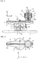
- a measuring device 1 is shown in section attached to a carriage 2 of a machine tool.
- the measuring device 1 consists of a base body 3, which is used for attachment to the carriage 2 and is the carrier of an angle measuring device 4.
- the base body 3 has a precise and play-free air bearing 5 for the rotatable mounting of a component 6 about a predetermined axis of rotation D1.
- the rotation of the component 6 relative to the base body 3 is measured by means of the angle measuring device 4, preferably an incremental rotary pulse generator.
- a length measuring device 10 is provided parallel to the linear guide 7.
- This length measuring device 10 consists of a material measure 10.1 which is arranged in the form of an incremental scale along the linear guide 7 and has a length which corresponds at least approximately to the possible travel path of the machine parts 2, 9 which are moved relative to one another.
- the scale 10.1 is attached directly to a surface of the linear guide 7.
- the incremental division of the scale 10.1 is scanned by a scanning unit 10.2 known per se to form position-dependent electrical signals.
- the scanning unit 10.2 is fixedly attached to a measuring slide 11 of the measuring element 8.
- this mounting consists of a total of one linear guide 13 and three rotary bearings 14, 15, 16 about three axes of rotation D2, D3, D4.
- a carrier 17 is provided which can be moved relative to the measuring slide 11 via the above-mentioned bearings 13 to 16.
- the linear guide 13 is formed from two bolts 13.1 and 13.2 fastened to the measuring slide 11, with which two corresponding bushes 13.3 and 13.4 interact, which thus cause a longitudinal movement between the measuring slide 11 and the carrier 17 along the axis of rotation D2 in the Z direction enable.
- This longitudinal movement in the Z direction is measured by at least one further length measuring device 18 to 21.
- this length measurement is carried out by means of several probes 18 to 21 which are fastened in the carrier 17 and whose probe bolts 18.1 to 21.1 rest on a surface 11.1 of the measuring slide 11 provided at right angles to the axis of rotation D1.
- the measurement of the angle of rotation about the axis of rotation D2 is measured by an angle measuring device 22, the scanning unit of which is connected to the carrier 17, that is to say the spindle 9, and the graduated disk of which is connected to the measuring slide 11.
- a further rotary movement of the carrier 17 relative to the measuring slide 11 is possible about the axis of rotation D3 via the rotary bearing 15.
- Another rotary bearing 16 enables the rotary movement of the carrier 17 relative to the measuring slide 11 about the axis of rotation D4.
- the rotary movements about the axes of rotation D3 and D4 are measured by the four spatially arranged buttons 18 to 21 by evaluating the length difference of two symmetrically opposite buttons 18, 20 and 19, 21.
- these rotary movements can also be measured directly by means of angle measuring devices attached to the individual rotary axes D3 and D4.
- the gimbal shown is particularly advantageous. This mounting ensures that the three mutually perpendicular axes of rotation D2, D3 and D4 intersect at a common pivot point.
- the bearing could also consist of a ball, which is rotatably mounted in a ball socket.
- a flat surface 17.1 can also be on the carrier 17 and the buttons 18 to 21 on the measuring slide 11.
- the scanning head of this length measuring device would be attached to the measuring slide 11 and the scale to the carrier 17.
- the scanning head can also be attached to the carrier 17, but this would have the effect that electrical lines from the measuring slide 11 and from the carrier 17 have to be led to an evaluation unit.
- the bolts 13.1 and 13.2 of the measuring carriage 11 form with the bushes 13.3 and 13.4, which are fastened to the carrier 17, a releasable coupling between the measuring carriage 11 and the carrier 17.
- This releasable coupling enables automated coupling, which is shown in FIG. If a machine tool is to be checked, the carrier 17 is automatically removed from a tool magazine, for example, and fastened to the spindle 9. So that a predetermined positional relationship during this movement between the universal joint 14, 15, 16, and the carrier 17 is retained until the bushings 13.3. and 13.4 are positioned in the associated bolts 13.1 and 13.2, the sockets 13.3, 13.4 are fixed by means of two controllable electromagnets 23, 24.
- the fixation takes place by the electromagnets 23, 24 extending two fixing elements 25, 26 in the direction of the bushes 13.3, 13.4 and interacting with them until the operating position shown in FIG. 4 is reached.
- the electromagnets 23, 24 are switched off, as a result of which the fixing elements 25, 26 are withdrawn by spring force and thus the operative connection with the sockets 13.3, 13.4 is released and free movement between the carrier 17 and the measuring slide 11 is made possible.
- the base body 3 with the linear guide 7 and the length measuring device 10 is also positioned in a numerically controlled manner by a pallet changer on the slide 2 of the machine tool.
- these two parts are clamped by means of a fixing element 30.
- Another fixing element 31 is provided for clamping between the component 6 and the measuring slide 11. Both fixing elements 30, 31 are controlled, for example, via an electromagnet like the fixing elements 25, 26 according to FIG. 4.
- sensors for example contactlessly operating sensors, are arranged in order to report the end positions reached after the successful coupling process to an evaluation device 27 and only to let the measuring program run automatically when the coupling is successful.
- the evaluation device 27 is shown in addition to the section of the measuring device according to the invention according to Figure 1, the evaluation device 27 is shown.
- the position measurement values P18 to P21 of the four buttons 18 to 21 are fed to a counter unit 27.1 of the evaluation device 27 and the tilt angles about the two axes of rotation D3 and D4 are determined therefrom.
- the position measurement values P4, P22 of the two angle measuring devices 4 and 22 are fed to a further counter unit 27.2 and the rotary movements about the two axes of rotation D1 and D2 are determined therefrom.
- a further counter unit 27.3 is provided for evaluating the position measurement values P10 of the length measuring device 10.
- the static and dynamic positional deviations are determined from all measurement results using evaluation software 27.4.
- the evaluation unit 27 also controls the fixing elements 30, 31 by means of separate lines P30, P31.
- a check of the geometric accuracy of a CNC machine can be carried out repeatedly not only during the initial start-up but also by the user himself after defined periods of time in order to realize controlled manufacturing processes with increasingly narrow tolerance limits.
- the simultaneous measurement of lengths and angles enables the clear establishment of an error matrix for software compensation of static and dynamic deviation parameters.
- the measurements can be carried out with little expenditure of time and personnel. Repetitive measurements are carried out with a small amount of measuring equipment using fixed measurement programs.
- the measuring device 1 has six degrees of freedom, four rotary (about the axes of rotation D1, D2, D3, D4) and two translational (X and Z directions) joints allow the recording of individual deviations independently of one another.
- a 2D evaluation can be carried out in polar coordinates.
- the yaw angle can be determined during a linear movement along the guide 7.
- the yaw angle results from the difference value of the position measurement values P4 and P22 of the angle measuring devices 4 and 22.
- the behavior of additional axes can be detected with the angle measuring device 22, which is particularly advantageous in the case of robots or also in the case of controlled rotatable spindles of machine tools.
- the length measuring device 10 eliminates any restriction due to small stylus strokes, so that a rapid variation of the circle diameter during the circular shape test and also other trajectory curves such as rectangles and polygons can be examined.
- the angle measuring devices 4, 22 a real angle measurement is possible and no calculation of the angular position from the feed rate and time.
- the length measuring devices 10, 18 to 21 and the angle measuring devices 4, 22 are preferably photoelectric incremental systems, but they can also work according to other physical principles such as capacitive or magnetic. Interferometers are also suitable as length measuring devices 10, 18 to 21.
- the evaluation software 27.4 and the counter units 27.1, 27.2, 27.3 can be installed on a measuring PC or a CNC control.
- the evaluation software 27.4 can also contain the possible measurement sequences for testing a CNC control.
- a test program for an automated quick acceptance of a CNC-controlled machine tool for the XY plane can contain the following measuring runs.
- FIG 8 some of the possible dynamic test methods for CNC machines are listed and the measurement diagrams are shown.
- the measurement diagrams can be displayed on the CNC control screen for control purposes and, if necessary, printed out using a printer.
Abstract
Description
Die Erfindung betrifft eine Meßvorrichtung zur Kontrolle der geometrischen und dynamischen Genauigkeit zweier relativ zueinander bewegter Maschinenteile.The invention relates to a measuring device for checking the geometric and dynamic accuracy of two machine parts moving relative to one another.
Werkzeugmaschinen sind mit Fehlern behaftet, welche Maß-, Form- und Lagefehler am Werkstück bewirken. Bei NC-Maschinen kommen noch dynamische Einflüsse, die von Steuerungen und Vorschub-Regelkreisen resultieren, hinzu. Diese bewirken, daß die vom Werkzeug relativ zum Werkstück abgefahrene Bahn von der programmierten Bahn abweicht.Machine tools are subject to errors that cause dimensional, shape and position errors on the workpiece. In the case of NC machines, there are also dynamic influences that result from controls and feed control loops. These cause the path traversed by the tool relative to the workpiece to deviate from the programmed path.
Zur Beurteilung der Genauigkeit der NC-Maschine gilt es, die geometrischen und die dynamischen Fehler zu messen. In allen Fällen ist es möglich, eine Probebearbeitung an einem ausgewählten Werkstück durchzuführen und dieses anschließend zu vermessen. Dabei ist es aber äußerst schwierig, die Fehlerursachen zu analysieren, weil noch die technologischen Einflüsse vom Werkzeug und den Schnittbedingungen hinzukommen. Man trachtet daher, Methoden und Vorrichtungen zu entwickeln, um an der Maschine selbst die Abweichung der fehlerbehafteten Bahn von der programmierten Bahn zu messen. Zur Überprüfung der geometrischen Genauigkeit von NC-Werkzeugmaschinen sind etliche Vorrichtungen und Verfahren bekannt. Dabei gewinnt der sogenannte Kreisformtest zunehmende Bedeutung. Der Kreisformtest erlaubt die Überprüfung der dynamischen Eigenschaften der NC-Maschine im Bahnsteuerbetrieb sowie Aussagen über die Maschinengeometrie. Als Bahn bietet sich ein Kreis an, weil er von allen bahngesteuerten NC-Maschinen in Form der Zirkularinterpolation realisiert werden kann und weil die Messung eines Kreises relativ einfach zu bewerkstelligen ist.To assess the accuracy of the NC machine, it is important to measure the geometric and dynamic errors. In all cases it is possible to carry out a test machining on a selected workpiece and then measure it. However, it is extremely difficult to analyze the causes of errors, because there are still technological ones Influences from the tool and the cutting conditions are added. The aim is therefore to develop methods and devices for measuring the deviation of the defective path from the programmed path on the machine itself. A number of devices and methods are known for checking the geometric accuracy of NC machine tools. The so-called circular shape test is becoming increasingly important. The circular shape test allows the dynamic properties of the NC machine to be checked in path control mode as well as statements about the machine geometry. A circle offers itself as a path because it can be implemented by all path-controlled NC machines in the form of circular interpolation and because the measurement of a circle is relatively easy to do.
Zur Erzeugung einer Kreisbahn sind auf einer bahngesteuerten NC-Werkzeugmaschine zwei gradlinig bewegte und rechtwinkelig zueinander angeordnete Maschinenkomponenten, zum Beispiel die zwei Einheiten eines Kreuztisches, nach einem Sinus- und Cosinusgesetz synchron so zu bewegen, daß als resultierende Bewegung die besagte Kreisbahn entsteht. Infolge der beschränkten Dynamik der beiden beteiligten Regelkreise, infolge mechanischer Unvollkommenheiten und weiterer Störeinflüsse weicht der so erzeugte Kreis von dem idealen, fehlerfreien Kreis mehr oder weniger ab. Markant ist beispielsweise der Einfluß der Geschwindigkeit, der sich üblicherweise in einer Zunahme der Kreisverzerrungen bei Erhöhungen der Vorschubgeschwindigkeiten zeigt.To create a circular path, two machine components that are moved in a straight line and at right angles to each other, for example the two units of a cross table, must be moved synchronously on a path-controlled NC machine tool according to a sine and cosine law so that the resulting circular path is created as the resultant movement. As a result of the limited dynamics of the two control loops involved, as a result of mechanical imperfections and further interference, the loop generated in this way deviates more or less from the ideal, error-free loop. The influence of the speed, for example, which is usually shown in an increase in the circular distortions with increases in the feed speeds, is striking.
Beim Kreisformtest geht es darum, diese Kreisformabweichungen zu messen und das Ergebnis auszuwerten um Rückschlüsse auf die Güte der NC-Maschine abzuleiten.The circular shape test is about measuring these circular shape deviations and evaluating the result in order to draw conclusions about the quality of the NC machine.
Im US-Patent 4,435,905 wird eine Vorrichtung zur Durchführung des Kreisformtests beschrieben, die aus einem Stab besteht, an dessen Enden Kugeln angebracht sind, die in je einem Widerlager gelagert sind. Zur Messung werden die beiden Widerlager an der NC-Maschine derart befestigt, daß ihre Positionen den Positionen von Werkzeugen und Werkstücken entsprechen. Der Stab besteht aus zwei Teilen, die längsverschieblich miteinander verbunden sind, so daß die Stablänge variabel ist. Die Verschiebung der beiden Teile zueinander wird durch ein integriertes Längenmeßsystem erfaßt. Wird ein Stabende auf einer Kreisbahn um das andere Ende bewegt, so entsprechen die Meßwerte den Kreisformabweichungen.US Pat. No. 4,435,905 describes a device for carrying out the circular shape test, which consists of a rod, at the ends of which balls are attached, which are each supported in an abutment. For measurement, the two abutments are attached to the NC machine in such a way that their positions correspond to the positions of tools and workpieces. The rod consists of two parts, which are connected to one another in a longitudinally displaceable manner, so that the rod length is variable. The displacement of the two parts to each other is recorded by an integrated length measuring system. If a rod end is moved on a circular path around the other end, the measured values correspond to the circular shape deviations.
Eine analoge Problematik gilt für Industrieroboter. Um Aussagen über die Genauigkeit eines Roboters treffen zu können, müssen die Bahnfehler der Roboterhand gemessen werden, wenn diese sich entlang einer programmierbaren Bahn bewegt. Auch zur Überprüfung der Bahngenauigkeit eines Industrieroboters bietet sich der Kreisformtest an. Das Problem ist hier jedoch weitaus komplexer als bei einer NC-Werkzeugmaschine, weil an der Bahnerzeugung nicht nur zwei Bewegungskomponenten beteiligt sind, sondern bis zu sechs Bewegungen synchron überlagert sind.An analogous problem applies to industrial robots. In order to be able to make statements about the accuracy of a robot, the path errors of the robot hand must be measured when it moves along a programmable path. The circular shape test can also be used to check the path accuracy of an industrial robot. However, the problem here is far more complex than with an NC machine tool, because not only two motion components are involved in the path generation, but up to six movements are synchronously superimposed.
Bei einem der üblichen Knickarmroboter, welcher ausschließlich Drehgelenke besitzt, sind dies: drei Positionsgelenke im Roboterkörper und drei Orientierungsgelenke in der Roboterhand.In the case of one of the usual articulated arm robots, which has only swivel joints, these are: three position joints in the robot body and three orientation joints in the robot hand.
Um nun auch bei derartigen Maschinen die geometrische und dynamische Genauigkeit bestimmen zu können, wurde eine neue Meßvorrichtung entwickelt, die in der DE 44 19 909 A1 beschrieben ist und von der diese Erfindung ausgeht.In order to be able to determine the geometric and dynamic accuracy also in such machines, a new measuring device has been developed, which is described in DE 44 19 909 A1 and from which this invention is based.
Gemäß der DE 44 19 909 A1 besteht die Meßvorrichtung aus einem inertialfest montierten Grundkörper, auf dem ein Arm drehbar gelagert ist, der in seinem Endbereich eine Radialführung für ein mit einem zu prüfenden Maschinenteil lösbar verbundenes Antastelement aufweist. Zur Erfassung der Kreisbahnabweichung des Antastelementes ist ein mit diesem zusammenwirkendes, radial zur Drehachse des Armes angeordnetes Längenmeßgerät am Arm befestigt. Zusätzlich ist am Endbereich des Armes ein weiteres Längenmeßgerät parallel zur Drehachse des Armes zur Messung der axialen Verlagerung des Antastelementes vorgesehen.According to DE 44 19 909 A1, the measuring device consists of an inertially fixed base body, on which an arm is rotatably mounted, which in its end region has a radial guide for a probe element detachably connected to a machine part to be tested. In order to record the circular path deviation of the contact element, a length measuring device, which cooperates with it and is arranged radially to the axis of rotation of the arm, is attached to the arm. In addition, a further length measuring device is provided at the end region of the arm parallel to the axis of rotation of the arm for measuring the axial displacement of the contact element.
Das radial zur Drehachse des Armes angeordnete Längenmeßgerät ist ein Taster mit einem sehr geringen Meßbereich, so daß ausschließlich die Abweichungen von einer vorgegebenen Kreisbahnbewegung gemessen werden können.The length measuring device arranged radially to the axis of rotation of the arm is a probe with a very small measuring range, so that only the deviations from a predetermined circular path movement can be measured.
Aufgabe der Erfindung ist es, eine Meßvorrichtung zu schafften, mit welcher mit geringem Aufwand die geometrische und dynamische Genauigkeit von Maschinen erfaßt werden kann, und die vielseitig einsetzbar ist.The object of the invention is to provide a measuring device with which the geometric and dynamic accuracy of machines can be detected with little effort, and which is versatile.
Diese Aufgabe wird von einer Meßvorrichtung mit den Merkmalen des Anspruches 1 gelöst.This object is achieved by a measuring device with the features of
Mit den in den abhängigen Ansprüchen angegebenen Merkmalen wird die Meßvorrichtung in besonders vorteilhafter Weise ausgestaltet.With the features specified in the dependent claims, the measuring device is designed in a particularly advantageous manner.
Die besonderen Vorteile der Erfindung liegen darin, daß die Meßvorrichtung universell für Messungen von Kreisbewegungen, aber auch von Linearbewegungen innerhalb des gesamten Verfahrweges der relativ zueinander bewegten Maschinenteile geeignet ist. Bei allen Bewegungen erfolgt eine Simultanmessung von Linear- und Drehbewegungen, so daß die Meßvorrichtung auch zur Prüfung von Roboterbewegungen zur Erfassung aller Achsbewegungen geeignet ist. Trotz der universellen Einsatzbarkeit der Meßvorrichtung ist sie relativ einfach und robust aufgebaut, da sie aus Standardmeßsystemen besteht.The particular advantages of the invention are that the measuring device is universal for measurements of circular movements, but also of linear movements is suitable within the entire travel path of the machine parts moving relative to one another. All movements involve simultaneous measurement of linear and rotary movements, so that the measuring device is also suitable for testing robot movements to record all axis movements. Despite the universal applicability of the measuring device, it is relatively simple and robust, since it consists of standard measuring systems.
Anhand von Ausführungsbeispielen wird die Erfindung nachstehend mit Hilfe der Zeichnungen näher erläutert.Based on exemplary embodiments, the invention is explained in more detail below with the aid of the drawings.
Es zeigt
Figur 1- einen Schnitt einer erfindungsgemäßen Meßvorrichtung,
Figur 2- eine Draufsicht der Meßvorrichtung gemäß
Figur 1, Figur 3- einen Schnitt einer weiteren Meßvorrichtung,
Figur 4- einen vergrößerten Querschnitt des Meßelementes aus
Figur 1, Figur 5- einen Schnitt des Meßelementes gemäß der
Figur 4 entlang der Linie V-V, Figur 6- einen weiteren Schnitt des Meßelementes aus
Figur 1 im entkoppelten Zustand, Figur 7- einen weiteren Schnitt der erfindungsgemäßen Meßvorrichtung mit einer Auswerteeinrichtung und
Figur 8- eine Aufstellung einiger möglicher Testmethoden.
- Figure 1
- 2 shows a section of a measuring device according to the invention,
- Figure 2
- 2 shows a top view of the measuring device according to FIG. 1,
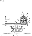
- Figure 3
- 2 shows a section of a further measuring device,
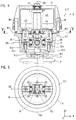
- Figure 4
- 2 shows an enlarged cross section of the measuring element from FIG. 1,
- Figure 5
- 3 shows a section of the measuring element according to FIG. 4 along the line VV,
- Figure 6
- 1 shows a further section of the measuring element from FIG. 1 in the decoupled state,
- Figure 7
- a further section of the measuring device according to the invention with an evaluation device and
- Figure 8
- a list of some possible test methods.
In Figur 1 ist eine erfindungsgemäße Meßvorrichtung 1 im Schnitt auf einem Schlitten 2 einer Werkzeugmaschine befestigt dargestellt. Die Meßvorrichtung 1 besteht aus einem Grundkörper 3, der zur Befestigung am Schlitten 2 dient und der Träger eines Winkelmeßgerätes 4 ist. Der Grundkörper 3 besitzt ein präzises und spielfreies Luftlager 5 zur drehbaren Lagerung eines Bauteiles 6 um eine vorgegebene Drehachse D1. Die Drehung des Bauteiles 6 gegenüber dem Grundkörper 3 wird mittels des Winkelmeßgerätes 4, vorzugsweise eines inkrementalen Drehimpulsgebers, gemessen.In Figure 1, a measuring
Auf dem drehbar gelagerten Bauteil 6 befindet sich eine Linearführung 7 zur Führung eines Meßelementes 8, welches mit der Spindel 9 der Werkzeugmaschine lösbar verbunden ist. Wie aus der Draufsicht in Figur 2 zu sehen ist, gewährleistet die Linearführung 7 eine exakte radiale Längsbewegung des Meßelements 8 gegenüber dem Bauteil 6. Um dies zu gewährleisten, reicht die Linearführung 7 über den gesamten Verfahrweg zwischen Bauteil 6 und Meßelement 8 und besonders vorteilhaft auch über den gesamten möglichen Verfahrweg zwischen dem Schlitten 2 und der Spindel 9.A
Zur Messung der senkrecht zur Drehachse D1 verlaufenden Linearbewegungen zwischen dem Grundkörper 3 und dem Meßelement 8 ist parallel zur Linearführung 7 ein Längenmeßgerät 10 vorgesehen. Dieses Längenmeßgerät 10 besteht aus einer Maßverkörperung 10.1, welche in Form eines inkrementalen Maßstabes entlang der Linearführung 7 angeordnet ist und eine Länge aufweist, die zumindest in etwa dem möglichen Verfahrweg der relativ zueinander bewegten Maschinenteile 2, 9 entspricht. Im gezeigten Beispiel ist der Maßstab 10.1 direkt an einer Fläche der Linearführung 7 befestigt. Die inkrementale Teilung des Maßstabes 10.1 wird von einer an sich bekannten Abtasteinheit 10.2 zur Bildung von positionsabhängigen elektrischen Signalen abgetastet. Die Abtasteinheit 10.2 ist an einem Meßschlitten 11 des Meßelements 8 ortsfest angebracht.For measuring the linear movements between the
Um axiale Verschiebungen in Z-Richtung entlang der Drehachse D1 sowie Schwenkbewegungen zwischen der Spindel 9 und dem Meßschlitten 11 exakt messen zu können, ist im Meßelement 8 eine in allen Richtungen schwenkbare und drehbare Lagerung integriert. Diese Lagerung besteht gemäß den Figuren 4 und 5 aus insgesamt einer Linearführung 13 sowie drei Drehlagerungen 14, 15, 16 um drei Drehachsen D2, D3, D4.In order to be able to precisely measure axial displacements in the Z direction along the axis of rotation D1 and pivoting movements between the spindle 9 and the measuring
Zur Befestigung des Meßelementes 8 an der Spindel 9 ist ein Träger 17 vorgesehen, der über die genannten Lagerungen 13 bis 16 relativ zum Meßschlitten 11 bewegbar ist.To mount the measuring
Die Linearführung 13 ist im gezeigten Beispiel aus zwei am Meßschlitten 11 befestigten Bolzen 13.1 und 13.2 gebildet, mit denen zwei korrespondierende Buchsen 13.3 und 13.4 zusammenwirken, die somit eine Längsbewegung zwischen dem Meßschlitten 11 und dem Träger 17 entlang der Drehachse D2 in Z-Richtung ermöglichen. Diese Längsbewegung in Z-Richtung wird durch zumindest ein weiteres Längenmeßgerät 18 bis 21 gemessen. Im gezeigten Beispiel erfolgt diese Längenmessung mittels mehrerer Taster 18 bis 21, die im Träger 17 befestigt sind und deren Tastbolzen 18.1 bis 21.1 auf einer rechtwinkelig zur Drehachse D1 vorgesehenen Fläche 11.1 des Meßschlittens 11 aufliegen.In the example shown, the linear guide 13 is formed from two bolts 13.1 and 13.2 fastened to the measuring
Eine Drehbewegung der Spindel 9 relativ zum Meßschlitten 11 um die Drehachse D2, welche im Normalfall parallel zur Drehachse D1 verläuft, wird durch das Drehlager 14 gewährleistet. Die Messung des Drehwinkels um die Drehachse D2 wird von einem Winkelmeßgerät 22 gemessen, dessen Abtasteinheit mit dem Träger 17, also mit der Spindel 9, und dessen Teilscheibe mit dem Meßschlitten 11 verbunden ist.A rotary movement of the spindle 9 relative to the measuring
Eine weitere Drehbewegung des Trägers 17 relativ zum Meßschlitten 11 ist um die Drehachse D3 über das Drehlager 15 möglich. Ein weiteres Drehlager 16 ermöglicht die Drehbewegung des Trägers 17 relativ zum Meßschlitten 11 um die Drehachse D4. Die Drehbewegungen um die Drehachsen D3 und D4 werden durch die vier räumlich angeordneten Taster 18 bis 21 gemessen, indem die Längendifferenz zweier symmetrisch gegenüberliegender Taster 18, 20 und 19, 21 ausgewertet werden. Diese Drehbewegungen können aber auch mittels an den einzelnen Drehachsen D3 und D4 angebachten Winkelmeßgeräten direkt gemessen werden.A further rotary movement of the
Um voneinander unabhängige Drehbewegungen um die drei Drehachsen D2, D3 und D4 zu gewährleisten, und trotzdem eine stabile, kompakte und spielfreie Lagerung zu erreichen, ist die dargestellte kardanische Lagerung besonders vorteilhaft. Durch diese Lagerung wird erreicht, daß sich die drei senkrecht aufeinanderstehenden Drehachsen D2, D3 und D4 in einem gemeinsamen Drehpunkt schneiden. Alternativ könnte die Lagerung auch aus einer Kugel bestehen, welche in einer Kugelpfanne drehbar gelagert ist.To ensure independent rotary movements around the three axes of rotation D2, D3 and D4, and still a stable, compact and play-free bearing to achieve, the gimbal shown is particularly advantageous. This mounting ensures that the three mutually perpendicular axes of rotation D2, D3 and D4 intersect at a common pivot point. Alternatively, the bearing could also consist of a ball, which is rotatably mounted in a ball socket.
Wie in Figur 3 dargestellt ist, kann sich eine ebene Fläche 17.1 auch am Träger 17 und die Taster 18 bis 21 am Meßschlitten 11 befinden.As shown in Figure 3, a flat surface 17.1 can also be on the
Weiterhin besteht die Möglichkeit, anstelle der Taster 18 bis 21 nur ein Längenmeßgerät einzusetzen, wenn die Drehbewegungen um die Drehachsen D2 bis D4 mittels Winkelmeßgeräten gemessen werden. In diesem Fall wäre der Abtastkopf dieses Längenmeßgerätes am Meßschlitten 11 und der Maßstab am Träger 17 befestigt. Selbstverständlich kann auch der Abtastkopf am Träger 17 befestigt werden, was aber den Machteil hätte, daß elektrische Leitungen vom Meßschlitten 11 und vom Träger 17 zu einer Auswerteeinheit geführt werden müssen.It is also possible to use only one length measuring device instead of the
Die Bolzen 13.1 und 13.2 des Meßschlittens 11 bilden mit den Buchsen 13.3 und 13.4, welche am Träger 17 befestigt sind, eine lösbare Kupplung zwischen dem Meßschlitten 11 und dem Träger 17. Diese lösbare Kupplung ermöglicht ein automatisiertes Ankoppeln, was in Figur 6 dargestellt ist. Wenn eine Überprüfung einer Werkzeugmaschine durchgeführt werden soll, wird beispielsweise der Träger 17 automatisch gesteuert aus einem Werkzeugmagazin entnommen und an der Spindel 9 befestigt. Damit während dieser Bewegung eine vorgegebene Lagebeziehung zwischen dem Kardangelenk 14, 15, 16, und dem Träger 17 erhalten bleibt, bis die Buchsen 13.3. und 13.4 in den zugehörigen Bolzen 13.1 und 13.2 positioniert sind, werden die Buchsen 13.3, 13.4 mittels zweier ansteuerbarer Elektromagnete 23, 24 fixiert. Die Fixierung erfolgt, indem durch die Elektromagnete 23, 24 zwei Fixierelemente 25, 26 in Richtung der Buchsen 13.3, 13.4 ausgefahren werden und mit diesen zusammenwirken, bis die in Figur 4 gezeigte Betriebsstellung erreicht ist. In der Betriebsstellung werden die Elektromagnete 23, 24 abgeschaltet, wodurch die Fixierelemente 25, 26 durch Federkraft zurückgezogen werden und somit die Wirkverbindung mit den Buchsen 13.3, 13.4 gelöst und eine freie Bewegung zwischen Träger 17 und Meßschlitten 11 ermöglicht wird.The bolts 13.1 and 13.2 of the measuring
Um einen völlig automatisierten Meßablauf durchzuführen, ist es besonders vorteilhaft, wenn auch der Grundkörper 3 mit der Linearführung 7 und dem Längenmeßgerät 10 durch einen Palettenwechsler auf dem Schlitten 2 der Werkzeugmaschine numerisch gesteuert positioniert wird. Um während dieses Vorganges sowie des Ankoppelvorganges eine störende Relativbewegung zwischen dem Grundkörper 3 und dem drehbaren Bauteil 6 zu vermeiden, werden diese beiden Teile mittels eines Fixierelementes 30 geklemmt. Ein weiteres Fixierelement 31 ist zur Klemmung zwischen dem Bauteil 6 und dem Meßschlitten 11 vorgesehen. Beide Fixierelemente 30, 31 werden beispielsweise über einen Elektromagneten wie die Fixierelemente 25, 26 gemäß Figur 4 angesteuert.In order to carry out a completely automated measurement sequence, it is particularly advantageous if the
Bei einer weiteren vorteilhaften Ausgestaltung sind im Meßschlitten 11 und/oder im Träger 17 Sensoren, beispielsweise berührungslos arbeitende Sensoren, angeordnet, um die erreichten Endpositionen nach dem erfolgreichen Ankoppelvorgang an eine Auswerteeinrichtung 27 zu melden und erst bei erfolgreichem Ankoppeln das Meßprogramm automatisch ablaufen zu lassen.In a further advantageous embodiment In the measuring
In Figur 7 ist zusätzlich zum Schnitt der erfindungsgemäßen Meßvorrichtung gemäß Figur 1 die Auswerteeinrichtung 27 dargestellt. Die Positionsmeßwerte P18 bis P21 der vier Taster 18 bis 21 werden einer Zählereinheit 27.1 der Auswerteeinrichtung 27 zugeführt und daraus die Kippwinkel um die beiden Drehachsen D3 und D4 ermittelt. Einer weiteren Zählereinheit 27.2 werden die Positionsmeßwerte P4, P22 der beiden Winkelmeßgeräte 4 und 22 zugeführt und daraus die Drehbewegungen um die beiden Drehachsen D1 und D2 ermittelt. Eine weitere Zählereinheit 27.3 ist zur Auswertung der Positionsmeßwerte P10 des Längenmeßgerätes 10 vorgesehen. Mittels einer Auswertesoftware 27.4 werden aus allen Meßergebnissen die statischen und dynamischen Positionsabweichungen ermittelt. Durch die Auswerteeinheit 27 werden auch die Fixierelemente 30, 31 mittels separater Leitungen P30, P31 angesteuert.In Figure 7, in addition to the section of the measuring device according to the invention according to Figure 1, the
Mit der erfindungsgemäß ausgestalteten Meßvorrichtung 1 ist eine Überprüfung der geometrischen Genauigkeit einer CNC-Maschine nicht nur bei der Erstinbetriebnahme sondern auch vom Anwender selbst nach festgelegten Zeiträumen wiederkehrend durchführbar, um beherrschte Fertigungsprozesse mit immer enger gesteckten Toleranzgrenzen zu realisieren. Die Simultanmessung von Längen und Winkeln ermöglicht die eindeutige Aufstellung einer Fehlermatrix zur Software-Kompensation von statischen und dynamischen Abweichungskenngrößen. Die Messungen können mit geringem Zeit- und Personalaufwand durchgeführt werden. Durch fest vorgegebene Meßprogramme werden Wiederholungsmessungen bei kleinem Meßrüstaufwand durchgeführt.With the measuring
Grundsätzlich besitzt die Meßvorrichtung 1 sechs Freiheitsgrade, wobei vier rotatorische (um die Drehachsen D1, D2, D3, D4) und zwei translatorische (X- und Z-Richtung) Gelenke die Aufnahme von Einzelabweichungen unabhängig voneinander ermöglichen. Mit der Winkelinformation P4 des Drehtisches 3, 6 und der Radialposition P10 des Meßschlittens 11 kann eine 2D-Auswertung in Polarkoordinaten erfolgen.Basically, the measuring
Durch den Einsatz des Winkelmeßgerätes 22, mit dem Verdrehungen zwischen der Spindel 9 und dem Meßschlitten 11 um die Drehachse D2 gemessen werden, kann der Gierwinkel bei einer Linearbewegung entlang der Führung 7 bestimmt werden. Der Gierwinkel ergibt sich aus dem Differenzwert der Positionsmeßwerte P4 und P22 der Winkelmeßgeräte 4 und 22. Weiterhin kann mit dem Winkelmeßgerät 22 das Verhalten von Zusatzachsen erfaßt werden, was insbesondere bei Robotern oder auch bei gesteuert drehbaren Spindeln von Werkzeugmaschinen vorteilhaft ist.By using the
Durch das erfindungsgemäße Längenmeßgerät 10 entfällt jede Einschränkung durch kleine Tasterhübe, so daß eine rasche Variation des Kreisdurchmessers beim Kreisformtest und auch andere Bahnkurven wie Rechtecke und Polygone untersucht werden können. Durch die Verwendung der Winkelmeßgeräte 4, 22 ist eine echte Winkelmessung möglich und keine Berechnung der Winkellage aus Vorschubgeschwindigkeit und Zeit.The length measuring device 10 according to the invention eliminates any restriction due to small stylus strokes, so that a rapid variation of the circle diameter during the circular shape test and also other trajectory curves such as rectangles and polygons can be examined. By using the
Die Längenmeßgeräte 10, 18 bis 21 sowie die Winkelmeßgeräte 4, 22 sind vorzugweise lichtelektrische inkrementale Systeme, sie können aber auch nach anderen physikalischen Prinzipien wie kapazitiv oder magnetisch arbeiten. Als Längenmeßgeräte 10, 18 bis 21 bieten sich auch Interferometer an.The
Die Auswertesoftware 27.4 sowie die Zählereinheiten 27.1, 27.2, 27.3 können auf einem Meß-PC oder einer CNC-Steuerung installiert sein.The evaluation software 27.4 and the counter units 27.1, 27.2, 27.3 can be installed on a measuring PC or a CNC control.
Die Auswertesoftware 27.4 kann auch die möglichen Meßabläufe zur Prüfung einer CNC-Steuerung enthalten. Ein Testprogramm für eine automatisierte Schnellabnehme einer CNC-gesteuerten Werkzeugmaschine für die XY-Ebene kann folgende Meßläufe enthalten.The evaluation software 27.4 can also contain the possible measurement sequences for testing a CNC control. A test program for an automated quick acceptance of a CNC-controlled machine tool for the XY plane can contain the following measuring runs.
Während der Meßläufe werden sowohl bei den statischen als auch den dynamischen Messungen neben der Position auch Kippwinkel (Gieren, Rollen, Nicken) und Geradheitsabweichungen erfaßt.
- * Bewegung in X-Richtung:
- Positionsmessung mit statistischer Auswertung nach ISO 230-2 (z.B. 5 Zyklen)
- Dynamische Messung mit unmittelbarem Vergleich zum Maschinenmeßsystem
- Step-Response-Test bei Verkleinerung der Schrittweite
- * Bewegung in Y-Richtung:
- Positionsmessung mit statistischer Auswertung nach ISO 230-2 (z.B. 5 Zyklen)
- Dynamische Messung mit unmittelbarem Vergleich zum Maschinenmeßsystem
- Step-Response-Test bei Verkleinerung der Schrittweite
- * Kreisformtest:
- Kreisformtest bei niedriger Vorschubgeschwindigkeit im Uhrzeigersinn
- Kreisformtest bei niedriger Vorschubgeschwindigkeit im Gegenuhrzeigersinn
- Kreisformtest bei hoher Vorschubgeschwindigkeit im Uhrzeigersinn
- Kreisformtest bei hoher Vorschubgeschwindigkeit im Gegenuhrzeigersinn
- * Eckentest:
- Eckentest bei niedriger Vorschubgeschwindigkeit im Uhrzeigersinn
- Eckentest bei niedriger Vorschubgeschwindigkeit im Gegenuhrzeigersinn
- Eckentest bei hoher Vorschubgeschwindigkeit im Uhrzeigersinn
- Eckentest bei hoher Vorschubgeschwindigkeit im Gegenuhrzeigersinn
- * Movement in the X direction:
- Position measurement with statistical evaluation according to ISO 230-2 (e.g. 5 cycles)
- Dynamic measurement with direct comparison to the machine measurement system
- Step response test when the step size is reduced
- * Movement in the Y direction:
- Position measurement with statistical evaluation according to ISO 230-2 (e.g. 5 cycles)
- Dynamic measurement with direct comparison to the machine measurement system
- Step response test when the step size is reduced
- * Circular shape test:
- Circular shape test at low feed speed clockwise
- Circular shape test at low feed speed counterclockwise
- Circular shape test at high feed speed clockwise
- Circular shape test at high feed speed counterclockwise
- * Corner test:
- Corner test at low feed speed clockwise
- Corner test at low feed speed counterclockwise
- Corner test at high feed speed clockwise
- Corner test at high feed speed counterclockwise
In Figur 8 sind einige der möglichen dynamischen Testmethoden für CNC-Maschinen aufgelistet und die Meßdiagramme dazu dargestellt. Die Meßdiagramme können zur Kontrolle am Bildschirm der CNC-Steuerung angezeigt werden und gegebenenfalls mittels eines Druckers ausgedruckt werden.In Figure 8 some of the possible dynamic test methods for CNC machines are listed and the measurement diagrams are shown. The measurement diagrams can be displayed on the CNC control screen for control purposes and, if necessary, printed out using a printer.
Claims (16)
Priority Applications (5)
| Application Number | Priority Date | Filing Date | Title |
|---|---|---|---|
| DE59503072T DE59503072D1 (en) | 1995-02-23 | 1995-02-23 | Measuring device for checking the geometric and dynamic accuracy of NC machine tools and industrial robots |
| EP95102540A EP0729005B1 (en) | 1995-02-23 | 1995-02-23 | Measuring device for checking the geometrie and dynamic precision of NC machining tools and industrial robots |
| AT95102540T ATE169395T1 (en) | 1995-02-23 | 1995-02-23 | MEASURING DEVICE FOR CHECKING THE GEOMETRIC AND DYNAMIC ACCURACY OF NC MACHINE TOOLS AND INDUSTRIAL ROBOTS |
| JP8032338A JP2831610B2 (en) | 1995-02-23 | 1996-02-20 | measuring device |
| US08/606,446 US5767380A (en) | 1995-02-23 | 1996-02-23 | Measuring arrangement and method for checking the geometric and dynamic accuracy of two machine elements displaceable with respect to one another |
Applications Claiming Priority (1)
| Application Number | Priority Date | Filing Date | Title |
|---|---|---|---|
| EP95102540A EP0729005B1 (en) | 1995-02-23 | 1995-02-23 | Measuring device for checking the geometrie and dynamic precision of NC machining tools and industrial robots |
Publications (2)
| Publication Number | Publication Date |
|---|---|
| EP0729005A1 true EP0729005A1 (en) | 1996-08-28 |
| EP0729005B1 EP0729005B1 (en) | 1998-08-05 |
Family
ID=8219005
Family Applications (1)
| Application Number | Title | Priority Date | Filing Date |
|---|---|---|---|
| EP95102540A Expired - Lifetime EP0729005B1 (en) | 1995-02-23 | 1995-02-23 | Measuring device for checking the geometrie and dynamic precision of NC machining tools and industrial robots |
Country Status (5)
| Country | Link |
|---|---|
| US (1) | US5767380A (en) |
| EP (1) | EP0729005B1 (en) |
| JP (1) | JP2831610B2 (en) |
| AT (1) | ATE169395T1 (en) |
| DE (1) | DE59503072D1 (en) |
Cited By (4)
| Publication number | Priority date | Publication date | Assignee | Title |
|---|---|---|---|---|
| EP0951967A1 (en) * | 1998-04-25 | 1999-10-27 | Institut Für Fertigungstechnik Der Tu Graz | Test gauge for measuring the positional and track precisionof a moving machine part |
| CN103398685A (en) * | 2013-07-11 | 2013-11-20 | 裕克施乐塑料制品(太仓)有限公司 | Measuring tool for measuring width of narrow cylindrical groove |
| CN103453823A (en) * | 2013-09-10 | 2013-12-18 | 大连理工大学 | Pipeline geometric size measuring machine |
| CN105643366A (en) * | 2016-04-12 | 2016-06-08 | 莱芜钢铁集团有限公司 | Auxiliary component for levelness correction of horizontal guide rail of machine tool and method |
Families Citing this family (10)
| Publication number | Priority date | Publication date | Assignee | Title |
|---|---|---|---|---|
| SE9904837L (en) * | 1999-12-29 | 2001-02-26 | Scania Cv Ab | Process and apparatus for machine testing |
| JP2001221531A (en) * | 2000-02-04 | 2001-08-17 | Mitsubishi Heavy Ind Ltd | Air conditioner |
| DE10018214A1 (en) * | 2000-04-12 | 2001-10-25 | Dreier Technology Ag Chur | Method and device for measuring manufacturing machines |
| US7040033B2 (en) * | 2001-10-05 | 2006-05-09 | Trustees Of Stevens Institute Of Technology | Six degrees of freedom precision measuring system |
| GB0417536D0 (en) * | 2004-08-06 | 2004-09-08 | Renishaw Plc | The use of surface measurement probes |
| EP1852674B1 (en) * | 2006-05-05 | 2015-09-09 | Dr. Johannes Heidenhain GmbH | Measuring device for determining the relative displacement between two components |
| SE530573C2 (en) * | 2006-11-16 | 2008-07-08 | Hexagon Metrology Ab | Method and apparatus for compensating geometric errors in processing machines |
| CN102393174B (en) * | 2011-08-25 | 2013-11-13 | 桐乡市易锋机械厂 | method for measuring center distance of piston |
| EP3062180B1 (en) * | 2015-02-25 | 2018-07-11 | Siemens Aktiengesellschaft | Method for verifying the position accuracy of a machine part which can be adjusted relative to at least one axle by means of a drive and a control |
| CN105773303A (en) * | 2016-04-12 | 2016-07-20 | 莱芜钢铁集团有限公司 | Milling machine rectilinear rising and falling precision correction auxiliary component and method |
Citations (8)
| Publication number | Priority date | Publication date | Assignee | Title |
|---|---|---|---|---|
| EP0155084A1 (en) * | 1984-02-16 | 1985-09-18 | Kabushiki Kaisha Toshiba | Device for measuring the shape of a three-dimensional object |
| GB2203837A (en) * | 1987-04-06 | 1988-10-26 | Mitutoyo Corp | Apparatus and method for spatial coordinate measurement |
| JPH02139112A (en) * | 1988-11-16 | 1990-05-29 | Toyoda Mach Works Ltd | Profile grinding machine |
| US5028180A (en) * | 1989-09-01 | 1991-07-02 | Sheldon Paul C | Six-axis machine tool |
| FR2658442A1 (en) * | 1990-02-22 | 1991-08-23 | Jobs Spa | MULTIFUNCTION THREE DIMENSIONAL DIGITAL CONTROL. |
| US5111590A (en) * | 1989-05-23 | 1992-05-12 | Park Joon Ho | Measuring method of machine tool accuracy using a computer aided kinematic transducer link and its apparatus |
| EP0545658A2 (en) * | 1991-12-02 | 1993-06-09 | General Electric Company | Automated maintenance system for computer numerically controlled machines |
| EP0597299A2 (en) * | 1992-11-12 | 1994-05-18 | Carl Zeiss | coordinate measuring machine |
Family Cites Families (7)
| Publication number | Priority date | Publication date | Assignee | Title |
|---|---|---|---|---|
| US4435905A (en) * | 1982-03-15 | 1984-03-13 | The United States Of America As Represented By The United States Department Of Energy | Telescoping magnetic ball bar test gage |
| DE3930223A1 (en) * | 1989-09-11 | 1991-03-14 | Wild Leitz Messtechnik | TEST BODY FOR COORDINATE MEASURING DEVICES FROM STICK SEGMENTS |
| US5400638A (en) * | 1992-01-14 | 1995-03-28 | Korea Institute Of Science And Technology | Calibration system for compensation of arm length variation of an industrial robot due to peripheral temperature change |
| JP2809295B2 (en) * | 1992-03-26 | 1998-10-08 | 株式会社東京精密 | Coordinate measuring machine and its measuring method |
| AT398246B (en) * | 1993-06-11 | 1994-10-25 | Frank Adolf Dipl Ing Dr | DEVICE FOR CONTROLLING THE GEOMETRIC AND DYNAMIC ACCURACY OF AN NC CONTROLLED WORK HEAD |
| US5341574A (en) * | 1993-06-29 | 1994-08-30 | The United States Of America As Represented By The Department Of Energy | Coordinate measuring machine test standard apparatus and method |
| US5533271A (en) * | 1994-08-23 | 1996-07-09 | Callaghan, Jr.; Robert P. | Long range sliding ball bar test gage |
-
1995
- 1995-02-23 EP EP95102540A patent/EP0729005B1/en not_active Expired - Lifetime
- 1995-02-23 AT AT95102540T patent/ATE169395T1/en not_active IP Right Cessation
- 1995-02-23 DE DE59503072T patent/DE59503072D1/en not_active Expired - Fee Related
-
1996
- 1996-02-20 JP JP8032338A patent/JP2831610B2/en not_active Expired - Fee Related
- 1996-02-23 US US08/606,446 patent/US5767380A/en not_active Expired - Fee Related
Patent Citations (8)
| Publication number | Priority date | Publication date | Assignee | Title |
|---|---|---|---|---|
| EP0155084A1 (en) * | 1984-02-16 | 1985-09-18 | Kabushiki Kaisha Toshiba | Device for measuring the shape of a three-dimensional object |
| GB2203837A (en) * | 1987-04-06 | 1988-10-26 | Mitutoyo Corp | Apparatus and method for spatial coordinate measurement |
| JPH02139112A (en) * | 1988-11-16 | 1990-05-29 | Toyoda Mach Works Ltd | Profile grinding machine |
| US5111590A (en) * | 1989-05-23 | 1992-05-12 | Park Joon Ho | Measuring method of machine tool accuracy using a computer aided kinematic transducer link and its apparatus |
| US5028180A (en) * | 1989-09-01 | 1991-07-02 | Sheldon Paul C | Six-axis machine tool |
| FR2658442A1 (en) * | 1990-02-22 | 1991-08-23 | Jobs Spa | MULTIFUNCTION THREE DIMENSIONAL DIGITAL CONTROL. |
| EP0545658A2 (en) * | 1991-12-02 | 1993-06-09 | General Electric Company | Automated maintenance system for computer numerically controlled machines |
| EP0597299A2 (en) * | 1992-11-12 | 1994-05-18 | Carl Zeiss | coordinate measuring machine |
Non-Patent Citations (2)
| Title |
|---|
| PATENT ABSTRACTS OF JAPAN vol. 14, no. 378 (M - 1011) 15 August 1990 (1990-08-15) * |
| W. GÖTZE ET AL.: "integration der cnc-messtechnik in fertigungslinien.", MICROTECHNIC, no. 1, ZURICH, CH, pages 16 - 19, XP000334948 * |
Cited By (7)
| Publication number | Priority date | Publication date | Assignee | Title |
|---|---|---|---|---|
| EP0951967A1 (en) * | 1998-04-25 | 1999-10-27 | Institut Für Fertigungstechnik Der Tu Graz | Test gauge for measuring the positional and track precisionof a moving machine part |
| US6433875B1 (en) | 1998-04-25 | 2002-08-13 | Institut für Fertigungstechnik Technische Universität Graz O. Univ. -Prof. Dipl. -Ing. Dr. Techn Adolf Frank | Measuring device for measuring the accuracy of the position and track of a moving machine element |
| CN103398685A (en) * | 2013-07-11 | 2013-11-20 | 裕克施乐塑料制品(太仓)有限公司 | Measuring tool for measuring width of narrow cylindrical groove |
| CN103398685B (en) * | 2013-07-11 | 2015-10-28 | 裕克施乐塑料制品(太仓)有限公司 | A kind of survey instrument for width of narrow cylindrical groove |
| CN103453823A (en) * | 2013-09-10 | 2013-12-18 | 大连理工大学 | Pipeline geometric size measuring machine |
| CN103453823B (en) * | 2013-09-10 | 2016-06-22 | 大连理工大学 | A kind of measuring machine of pipeline physical dimension |
| CN105643366A (en) * | 2016-04-12 | 2016-06-08 | 莱芜钢铁集团有限公司 | Auxiliary component for levelness correction of horizontal guide rail of machine tool and method |
Also Published As
| Publication number | Publication date |
|---|---|
| JPH091443A (en) | 1997-01-07 |
| US5767380A (en) | 1998-06-16 |
| JP2831610B2 (en) | 1998-12-02 |
| ATE169395T1 (en) | 1998-08-15 |
| EP0729005B1 (en) | 1998-08-05 |
| DE59503072D1 (en) | 1998-09-10 |
Similar Documents
| Publication | Publication Date | Title |
|---|---|---|
| EP0317967B1 (en) | Rotation-deflection arrangement for the feeler heads of coordinate-measuring devices | |
| DE3714862C2 (en) | ||
| EP1696289B1 (en) | Method for gauging a machine tool | |
| EP2760633B1 (en) | Machine tool and method for measuring a workpiece | |
| DE4110209C2 (en) | Device for adjusting a CNC-controlled grinding machine | |
| WO2015044210A1 (en) | Reduction of errors of a rotating device used during the determination of co-ordinates of a workpiece or during the machining of a workpiece | |
| EP0729005B1 (en) | Measuring device for checking the geometrie and dynamic precision of NC machining tools and industrial robots | |
| EP2972078A1 (en) | Method for correcting an angular deviation in the operation of a coordinate measuring device | |
| WO2014072314A1 (en) | Machine tool and method for measuring a workpiece | |
| EP3274655A1 (en) | Calibration of a rotating device attached to a movable part of a coordinate measuring device | |
| EP2835702B1 (en) | Method for measuring at least one rotation axis of a machine tool | |
| DE4212455C2 (en) | Method for measuring shaped elements on a coordinate measuring machine | |
| DE3234241C2 (en) | ||
| EP1019669B1 (en) | Device for detecting the position of two bodies | |
| DE102017103938A1 (en) | Device for measuring the roughness of a workpiece surface | |
| DE102008024444B4 (en) | Method and device for calibrating a coordinate measuring machine | |
| WO2016207303A1 (en) | Adapter element for assembling a rotational apparatus in the measurement space of a coordinate measuring machine | |
| DE19921325A1 (en) | Calibration device for parallel kinematic manipulator has sampler that can be fitted into manipulator and then moved relative to test piece having measurement points whose position and orientation are known | |
| DE60032635T2 (en) | METHOD AND DEVICE FOR TESTING TOOLING MACHINES | |
| DE102013210739B3 (en) | Coordinate measuring machine for measuring workpiece, has drive unit that exerts directed force on thrust unit, such that amount, direction and point of application can be chosen and torque acting on measuring unit is specific value | |
| AT398246B (en) | DEVICE FOR CONTROLLING THE GEOMETRIC AND DYNAMIC ACCURACY OF AN NC CONTROLLED WORK HEAD | |
| WO1994007187A1 (en) | Process for testing the working accuracy of an nc machine | |
| DE10203002B4 (en) | Device for calibrating a robot | |
| DE4323992A1 (en) | Check on operational accuracy of numerically controlled machine including robot - involves interpolator in generation of vectors for servo control of sliders guided around circular test track | |
| EP3507568B1 (en) | System and method for tactile measurement of a measurement object and use of said system |
Legal Events
| Date | Code | Title | Description |
|---|---|---|---|
| PUAI | Public reference made under article 153(3) epc to a published international application that has entered the european phase |
Free format text: ORIGINAL CODE: 0009012 |
|
| 17P | Request for examination filed |
Effective date: 19950317 |
|
| AK | Designated contracting states |
Kind code of ref document: A1 Designated state(s): AT CH DE FR GB IT LI SE |
|
| 17Q | First examination report despatched |
Effective date: 19970903 |
|
| GRAG | Despatch of communication of intention to grant |
Free format text: ORIGINAL CODE: EPIDOS AGRA |
|
| GRAG | Despatch of communication of intention to grant |
Free format text: ORIGINAL CODE: EPIDOS AGRA |
|
| GRAG | Despatch of communication of intention to grant |
Free format text: ORIGINAL CODE: EPIDOS AGRA |
|
| GRAH | Despatch of communication of intention to grant a patent |
Free format text: ORIGINAL CODE: EPIDOS IGRA |
|
| GRAG | Despatch of communication of intention to grant |
Free format text: ORIGINAL CODE: EPIDOS AGRA |
|
| GRAH | Despatch of communication of intention to grant a patent |
Free format text: ORIGINAL CODE: EPIDOS IGRA |
|
| RAP3 | Party data changed (applicant data changed or rights of an application transferred) |
Owner name: INSTITUT FUER FERTIGUNGSTECHNIK DER TU GRAZ |
|
| GRAH | Despatch of communication of intention to grant a patent |
Free format text: ORIGINAL CODE: EPIDOS IGRA |
|
| ITF | It: translation for a ep patent filed |
Owner name: DATA SOLLECITO LETT. INC.:02/10/98;DE DOMINICIS & |
|
| GRAA | (expected) grant |
Free format text: ORIGINAL CODE: 0009210 |
|
| RBV | Designated contracting states (corrected) |
Designated state(s): AT CH DE FR GB IT LI SE |
|
| AK | Designated contracting states |
Kind code of ref document: B1 Designated state(s): AT CH DE FR GB IT LI SE |
|
| REF | Corresponds to: |
Ref document number: 169395 Country of ref document: AT Date of ref document: 19980815 Kind code of ref document: T |
|
| REG | Reference to a national code |
Ref country code: CH Ref legal event code: NV Representative=s name: TROESCH SCHEIDEGGER WERNER AG Ref country code: CH Ref legal event code: EP |
|
| REF | Corresponds to: |
Ref document number: 59503072 Country of ref document: DE Date of ref document: 19980910 |
|
| ET | Fr: translation filed | ||
| GBT | Gb: translation of ep patent filed (gb section 77(6)(a)/1977) |
Effective date: 19981022 |
|
| PLBE | No opposition filed within time limit |
Free format text: ORIGINAL CODE: 0009261 |
|
| STAA | Information on the status of an ep patent application or granted ep patent |
Free format text: STATUS: NO OPPOSITION FILED WITHIN TIME LIMIT |
|
| 26N | No opposition filed | ||
| REG | Reference to a national code |
Ref country code: GB Ref legal event code: IF02 |
|
| PGFP | Annual fee paid to national office [announced via postgrant information from national office to epo] |
Ref country code: SE Payment date: 20050210 Year of fee payment: 11 Ref country code: FR Payment date: 20050210 Year of fee payment: 11 Ref country code: CH Payment date: 20050210 Year of fee payment: 11 |
|
| PGFP | Annual fee paid to national office [announced via postgrant information from national office to epo] |
Ref country code: AT Payment date: 20050211 Year of fee payment: 11 |
|
| PGFP | Annual fee paid to national office [announced via postgrant information from national office to epo] |
Ref country code: GB Payment date: 20050214 Year of fee payment: 11 |
|
| PG25 | Lapsed in a contracting state [announced via postgrant information from national office to epo] |
Ref country code: GB Free format text: LAPSE BECAUSE OF NON-PAYMENT OF DUE FEES Effective date: 20060223 Ref country code: AT Free format text: LAPSE BECAUSE OF NON-PAYMENT OF DUE FEES Effective date: 20060223 |
|
| PG25 | Lapsed in a contracting state [announced via postgrant information from national office to epo] |
Ref country code: SE Free format text: LAPSE BECAUSE OF NON-PAYMENT OF DUE FEES Effective date: 20060224 |
|
| PG25 | Lapsed in a contracting state [announced via postgrant information from national office to epo] |
Ref country code: LI Free format text: LAPSE BECAUSE OF NON-PAYMENT OF DUE FEES Effective date: 20060228 Ref country code: CH Free format text: LAPSE BECAUSE OF NON-PAYMENT OF DUE FEES Effective date: 20060228 |
|
| PGFP | Annual fee paid to national office [announced via postgrant information from national office to epo] |
Ref country code: IT Payment date: 20060228 Year of fee payment: 12 |
|
| REG | Reference to a national code |
Ref country code: CH Ref legal event code: PL |
|
| EUG | Se: european patent has lapsed | ||
| GBPC | Gb: european patent ceased through non-payment of renewal fee |
Effective date: 20060223 |
|
| REG | Reference to a national code |
Ref country code: FR Ref legal event code: ST Effective date: 20061031 |
|
| PG25 | Lapsed in a contracting state [announced via postgrant information from national office to epo] |
Ref country code: FR Free format text: LAPSE BECAUSE OF NON-PAYMENT OF DUE FEES Effective date: 20060228 |
|
| PGFP | Annual fee paid to national office [announced via postgrant information from national office to epo] |
Ref country code: DE Payment date: 20090219 Year of fee payment: 15 |
|
| PG25 | Lapsed in a contracting state [announced via postgrant information from national office to epo] |
Ref country code: IT Free format text: LAPSE BECAUSE OF NON-PAYMENT OF DUE FEES Effective date: 20070223 |
|
| PG25 | Lapsed in a contracting state [announced via postgrant information from national office to epo] |
Ref country code: DE Free format text: LAPSE BECAUSE OF NON-PAYMENT OF DUE FEES Effective date: 20100901 |