EP0729020A2 - Method and system for assessing the operating condition of a pressure regulator in a corrosive gas distribution system - Google Patents
Method and system for assessing the operating condition of a pressure regulator in a corrosive gas distribution system Download PDFInfo
- Publication number
- EP0729020A2 EP0729020A2 EP96400391A EP96400391A EP0729020A2 EP 0729020 A2 EP0729020 A2 EP 0729020A2 EP 96400391 A EP96400391 A EP 96400391A EP 96400391 A EP96400391 A EP 96400391A EP 0729020 A2 EP0729020 A2 EP 0729020A2
- Authority
- EP
- European Patent Office
- Prior art keywords
- pressure
- gas
- pressure regulator
- sensitive element
- determining
- Prior art date
- Legal status (The legal status is an assumption and is not a legal conclusion. Google has not performed a legal analysis and makes no representation as to the accuracy of the status listed.)
- Withdrawn
Links
Images
Classifications
-
- G—PHYSICS
- G01—MEASURING; TESTING
- G01M—TESTING STATIC OR DYNAMIC BALANCE OF MACHINES OR STRUCTURES; TESTING OF STRUCTURES OR APPARATUS, NOT OTHERWISE PROVIDED FOR
- G01M3/00—Investigating fluid-tightness of structures
- G01M3/02—Investigating fluid-tightness of structures by using fluid or vacuum
- G01M3/26—Investigating fluid-tightness of structures by using fluid or vacuum by measuring rate of loss or gain of fluid, e.g. by pressure-responsive devices, by flow detectors
- G01M3/28—Investigating fluid-tightness of structures by using fluid or vacuum by measuring rate of loss or gain of fluid, e.g. by pressure-responsive devices, by flow detectors for pipes, cables or tubes; for pipe joints or seals; for valves ; for welds
- G01M3/2876—Investigating fluid-tightness of structures by using fluid or vacuum by measuring rate of loss or gain of fluid, e.g. by pressure-responsive devices, by flow detectors for pipes, cables or tubes; for pipe joints or seals; for valves ; for welds for valves
-
- F—MECHANICAL ENGINEERING; LIGHTING; HEATING; WEAPONS; BLASTING
- F17—STORING OR DISTRIBUTING GASES OR LIQUIDS
- F17D—PIPE-LINE SYSTEMS; PIPE-LINES
- F17D1/00—Pipe-line systems
- F17D1/02—Pipe-line systems for gases or vapours
- F17D1/04—Pipe-line systems for gases or vapours for distribution of gas
Definitions
- the present invention relates to a method for detecting malfunctions or failures in pressure regulators used in corrosive gas distribution systems and a method for preventing such malfunctions or failures.
- Gas distribution systems including inert and non-inert gas distribution systems, are used in a wide range of applications.
- Inert gases are not usually a problem for the various parts of a gas distribution system.
- non-inert gases i.e., gases which may have a reaction with their environment, including reactive gases or corrosive gases, generate several problems related to their handling or transportation, particularly corrosive gases which may be very aggressive for their environment such as pipelines, valves, pressure regulators, etc.
- corrosive HBr gas is used in the manufacture of semiconductors.
- the corrosive HBr gas is stored in cylinders located in a cylinder cabinet outside the manufacturing facility.
- a gas distribution system is then provided to transport the corrosive gas to the appropriate place within the manufacturing facility.
- the gas distribution systems typically include many components for gas flow control, e.g., pressure regulators and mass flow controllers.
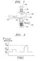
- the general features of such a pressure regulator valve are illustrated in FIG. 1 and include an inlet 22, an outlet 24 and a diaphragm 26.
- a restricted orifice 28 is provided in the diaphragm and defines a seat 30.
- a poppet 32 biased by a poppet spring 34 and provided with a poppet cap 40 is designed to engage the seat 30 to thereby control or regulate the flow through the restricted orifice 28.
- a pressure adjustment knob 36 connected to a load spring 38 is also provided to effect adjustment of the pressure regulator 20.
- One of the major causes of the aforementioned malfunction or failure of the pressure regulators is the corrosion of and/or the deposition of corrosion products on the area of the poppet 32 at which the pressure drop occurs (i.e., in the area of the restricted orifice 28). Since the space between the outer surface of the poppet 32 and the seat 30 is on the order of a few microns, the outer surface of the poppet 32 must be very smooth to achieve proper leak tightness and to control secondary gas flow. The presence of even a slight amount of corrosion and/or deposition on the outer surface of the poppet 32 can prevent achievement of the necessary leak tightness and can result in the occurrence of a secondary gas leak when the regulator is in the closed position.
- This type of internal leak in the pressure regulator can also arise due to corrosion of the poppet spring 34. Such corrosion can weaken the spring force of the poppet spring 34 and thereby inhibit the poppet 32 from fully engaging the seat 30 to close the restricted orifice 28.
- pressure regulator malfunction or failure can result from external leaks. That is, the corrosive gas flowing through the pressure regulator can cause pitting corrosion (i.e., tiny holes) in the diaphragm 26 of the pressure regulator 20. This external leak can cause the leakage of corrosive gas directly to the surrounding environment.
- the pressure regulators in the gas distribution system are typically replaced at specified intervals of time.
- the hope is that by replacing the pressure regulators at scheduled intervals, it will be possible to avoid situations in which the regulators fail.
- the regulators may experience corrosion problems that are more significant than expected, thereby raising the possibility that the regulators will fail prior to replacement.
- scheduled replacements oftentimes result in the replacement of pressure regulators which are not malfunctioning or on the verge of failure.
- a method of detecting malfunctions or failures of pressure regulators in a non-inert gas flow system, particularly a corrosive gas flow system, while in use includes the steps of flowing a non-inert or corrosive gas through a gas flow system which is provided with a pressure regulator, determining an operating output pressure of the pressure regulator in the gas flow system while the non-inert or corrosive gas is flowing through the system, continuously measuring the output pressure of the pressure regulator in the absence of the non-inert or corrosive gas flow through the system, and determining the existence of a malfunction or a failure of the pressure regulator when a pressure differential between the operating output pressure of the pressure regulator while the non-inert or corrosive gas is flowing through the system and the output pressure of the pressure regulator in the absence of gas flow exceeds a predetermined value.
- non-inert gases reactive gases or corrosive gases will be used alternatively to designate the same type of gases which are capable of having a reaction, usually a chemical reaction, with their environment such as pipes, valves, pressure regulators or the like.
- the existence of a malfunction of the pressure regulator is identified when the pressure differential exceeds a first predetermined value, and the existence of a failure of the pressure regulator is identified when the pressure differential exceeds a second predetermined value that is greater than the first predetermined value.
- a malfunction of the pressure regulator is identified when the pressure differential is between about 0.5 kgf/cm 2 and 1.0 kgf/cm 2 .
- the existence of a failure of the pressure regulator is determined when the pressure differential is greater than about 1.0 kgf/cm 2 .
- a method of assessing the operating condition of a component in a gas flow system includes flowing gas through a line of a gas flow system which contains such a component for regulating flow through the line, monitoring an output pressure adjacent an outlet of the component during flow of gas through the line and in the absence of gas flow through the line and determining the operating condition of the component on the basis of changes in the outlet pressure of the component in the absence of gas flow through the component.
- the existence of an external leak in the component is determined when the outlet pressure decreases during the absence of gas flow through the line. If the pressure differential between the outlet pressure of the component when gas is flowing through the line and the outlet pressure of the component in the absence of gas flow exceeds a first predetermined value, it is determined that the component is malfunctioning. On the other hand, if the pressure differential between the outlet pressure of the component when gas is flowing through the line and the outlet pressure of the component in the absence of gas flow exceeds a second predetermined value which is greater than the first predetermined value, it is determined that the component has failed.
- the invention relates to a method of assessing the existence of an external leak in a component having at least an open position where gas flows and having at least one closed position where gas does not flow, comprising the step of determining a decrease of the outlet pressure of the gas from the component, which is in closed position, while the gas under pressure is present on the inlet side of said component, compared to the pressure of the gas when the component is in open position.
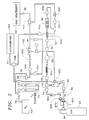
- FIG. 2 generally illustrates various features associated with a corrosive gas distribution system incorporating the features of the present invention.
- the gas flow distribution system illustrated in FIG. 2 is useful in the context of delivering corrosive HBr gas to a semiconductor manufacturing facility.
- the features of the present invention which are described in more detail below are equally applicable to any other type of corrosive gas or non-inert distribution systems which employ pressure regulators that are subject to malfunction or failure.
- a cylinder 42 of corrosive HBr gas is connected to the gas distribution system for purposes of providing a supply of HBr gas.
- the cylinder 42 is designed to be replaceable so that when the cylinder is emptied, another full cylinder can be connected to the system.
- the gas distribution system also includes several high pressure valves 44, 46, 48, several low pressure valves 501, 502, 503, 504, 505, 506, a low pressure air control valve 52, pressure sensors 54, 70 which measure the pressure of the corrosive gas HBr before and after the pressure regulator 68, a vacuum generator 56, a flow meter 58, a deep purge or cross purge unit 60, several check valves 621, 622, 623, several filters 641, 642 and a mass flow controller 66.
- a source of N 2 73 is provided and is connected with the distribution system by way of a house line 72.
- the source 73 can be a liquid nitrogen storage with an evaporator or an on-site N 2 plant or N 2 gas in a cylinder, or any other N 2 generator means.
- a N 2 purifier is also connected to the incoming N 2 line 72 to deliver high purity or ultrahigh purity N 2 as required by the standards of the electronic industry.
- the various parts of the gas distribution system described above are interconnected with appropriate tubing (e.g., SUS 316L EP tubings and SUS 316L BA tubings) having different size diameters as illustrated in FIG. 2.
- the gas distribution system also includes a pressure regulator 68 which can be of the general form illustrated in FIG. 1 for reducing the pressure in the cylinder 42 to the working pressure.
- the various high or low pressure valves control the various gas flow in two directions (on or off) while the check valves allow the gas to flow only in one direction.
- the deep purge unit DPU 60 comprises two pigtails 601, 602 which are connected to the valve 80 of the cylinder 42 and which assist in the gas purging procedure during the HBr cylinder exchange. (The deep purge unit, DPU, can be replaced by a cross purge unit.)
- the vacuum generator 56 evacuates gas from the system to a gas abatement device 151 through the line 78.
- the flow meter 58 measures the nitrogen flow rate in the system.
- the operation of the system shown in FIG. 2 involves three basic steps, namely the initial dry down step, the HBr flow step, and the cylinder exchange simulation. Each of these steps is described below.
- N 2 gas flows through the purifier 75, valve 44, deep purge unit (DPU) 60 and valve 46 to the system and the moisture level of the purge N 2 is measured by a hygrometer 707 attached to the end of the line 74.
- the purified N 2 (about 20 ppb H 2 O) is necessary only for the initial dry down of the complete line.
- a purified high grade N 2 is sufficient for purging of the deep purge unit 60 and the cylinder valve 80 during the cylinder change.
- a purified low grade N 2 is used for other purposes like pneumatic valve operation and dilution of corrosive gas before being sent to the gas abatement device 151.
- the valves 44, 48, 503, 505 and 506 remain closed.
- the opening of the cylinder valve 80 initiates gas flow from the cylinder 42 to the system through the deep purge unit 60.
- the input pressure (P) of the gas (cylinder pressure) is measured by the pressure sensor (PS) 54.
- the pressure sensor 70 indicates the output pressure from the regulator 68.
- the mass flow controller 66 controls the gas flow rate.
- a gas with a constant pressure and flow rate flows to the gas abatement device 151 through the line 78. Nitrogen gas flows through the valve 504 and dilutes the HBr gas in the connection 747 prior to entering the gas abatement device 151.
- the cylinder valve 80 is disconnected from the deep purge unit 60 and the opening of the valve 44 creates a N 2 flow from the pigtail bleed 601 to the atmosphere during the times the cylinder 42 is disconnected from the deep purge unit 60.
- the valve 80 of the cylinder 42 is reconnected to the deep purge unit 60.
- the atmospheric intrusion into the cylinder valve is removed by the same procedure that is used to remove the HBr at the beginning. The HBr flow can thereafter start again.
- the output pressure P F is constant or substantially constant with time so long as gas is flowing through the gas distribution system. If the gas flow stops as a result of, for example, the closing of a valve downstream of the pressure regulator, the output pressure P NF of the pressure regulator increases slightly in comparison to that which is reached when gas is flowing and then once again remains constant or substantially constant with respect to time.
- the operating condition of the pressure regulator can be assessed by continuously measuring the output pressure of the pressure regulator when gas is flowing through the system and in the absence of gas flow through the system, and monitoring the pressure differential ⁇ P that exists between the output pressure of the pressure regulator when gas is flowing through the system and the output pressure of the pressure regulator in the absence of gas flow.
- each system was provided with a pressure sensor 70 positioned immediately downstream of the pressure regulator 68 to continuously measure the output pressure of the pressure regulator 68.
- the three systems were operated so as to simulate conditions which would likely result in three different conditions of the pressure regulator -- a properly operating pressure regulator, a malfunctioning pressure regulator and a failed pressure regulator.
- the moisture level of the purging N 2 was monitored by a hygrometer 707 allowing down to approximately 20 ppb H 2 O concentration measurement (e.g., an electrolytic hygrometer like those sold by MEECO, Inc.) and connected to an output line 74 of each system. After several days (i.e., 1-2 days) of purging, the moisture level of the N 2 gas reached 100 ppb at the end of the lines. The purging was then stopped and a flow of pulsed HBr gas, controlled by the pneumatic valve 52, was introduced into each of the three test systems. During this pulsed HBr gas flow, the output pressure of the pressure regulator 68 of each test system was recorded constantly by the pressure transmitter 70 both in the presence of gas flow and in the absence of gas flow. The gas flow rate was between 100 standard cubic centimeter per minute and 1000 standard cubic centimeter per minute.
- the purging procedure after the simulated cylinder exchange was the same as that used in connection with the first test system.
- the only difference between the first and second systems involved the initial dry down described above in which the first system was dried down with baking while the latter was not.
- the N 2 cycle purge after the simulated cylinder exchange for the third test system was carried out in the same manner as that for the first and second test systems.
- the HBr purge after the N 2 cycle purge was not done. Therefore, the removal of contaminants that were introduced into the system during the cylinder change was not as efficient as in the case of the first system or the second system and so the extent of corrosion within the third system was significantly higher than in the case of the first and second systems.
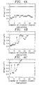
- the pressure differential ⁇ P of the regulator 68 for the first test system fluctuated only very slightly, and remained small and nearly constant with the number of cylinder change simulations as illustrated in the graph of FIG. 4A. Even after twenty-four cylinder exchange simulations, the pressure regulator 68 exhibited no abnormality and the pressure differential ⁇ P was always less than about 0.5 kgf/cm 2 .
- the pressure differential ⁇ P of the pressure regulator 68 for the second test system fluctuated significantly, and gradually increased to about 0.9 kgf/cm 2 with the number of cylinder exchange simulations as illustrated in the graph of FIG. 4B. After twenty-one cylinder exchange simulations, the pressure differential ⁇ P was less than 1.0 kgf/cm 2 . Although the pressure regulator 68 was still deemed usable, the high value of the pressure differential ⁇ P (about 0.9 kgf/cm 2 ) and the high fluctuations in the pressure differential ⁇ P indicated the onset of malfunction.
- the pressure regulator 68 from the second test system was found to have minor corrosion and minor deposition of corrosion products on the poppet which would tend to inhibit the leak tight closure of the restricted orifice 28 through engagement of the poppet 32 on the seat 30 of the pressure regulator. Also observed with respect to the pressure regulator 68 from the second test system was corrosion on the poppet spring 34 which would tend to inhibit or reduce the rebound ability of the poppet spring 34 in -the absence of gas flow. This deposition of corrosion products on the poppet 32 and corrosion on the poppet spring 34 were deemed to be the causes of the observed fluctuations in the pressure differential ⁇ P with respect to time as illustrated in the graph of FIG. 4B.
- the pressure differential ⁇ P of the pressure regulator 68 from the third test system fluctuated greatly and exceeded 1.0 kgf/cm 2 after only eleven cylinder change simulations as depicted in the graph of FIG. 4C.
- the pressure regulator 68 failed ( ⁇ P > 1.0 kgf/cm 2 ) much earlier than in the case of the pressure regulator for the first system.
- the pressure regulator 68 from the third test system exhibited a heavy deposition of corrosion products on the poppet 32 and heavy corrosion of the poppet spring 34, both of which inhibit the leak tight closure of the restricted orifice 28 through full engagement of the poppet 32 with the seat 30 of the pressure regulator. This heavy deposition of corrosion products on the poppet 32 and the heavy corrosion of the poppet spring 34 were deemed to be the cause of the failure of the pressure regulator of the third test system through internal leak.
- the variation in pressure differential AP with respect to time depends quite strongly on the purging procedure associated with the cylinder exchange (i.e., with the corrosion level in the system, particularly the pressure regulator).
- the pressure differential ⁇ P is quite small, on the order of less than 0.5 kgf/cm 2 , and does not fluctuate with time.
- the pressure differential ⁇ P is quite large, on the order of greater than 1.0 kgf/cm 2 , and gradually increases with time.
- the pressure differential ⁇ P can be regarded as an arbitrary unit for the indication of the operating condition of the pressure regulator in the following manner.
- the operating condition of a pressure regulator in a corrosive gas distribution system with respect to the presence or absence of internal or external leaks can be assessed by (continuously) monitoring or measuring the output pressure of the pressure regulator in the presence and absence of gas flow through the system. Knowing the output pressure of the pressure regulator when gas is flowing through the system and comparing that pressure to the output pressure of the regulator in the absence of gas flow to determine the magnitude of the pressure differential allows the operating condition of the regulator to be readily determined. This advantageously allows pressure regulator malfunctions to be detected at an early stage so that corrective action can be taken before the occurrence of a corrosive gas leakage. Thus, the safety as well as the productivity of the gas distribution system can be increased to a significant extent.
- This technique can be used manually as well as in computerized gas distribution systems to predict malfunctions automatically and correct them prior to the occurrence of a potentially harmful accident.
- the pressure differential ⁇ P and its variation with time can be automatically measured with the results being automatically fed to safety equipment so as to achieve safe and trouble free operation of the total corrosive gas distribution system.
- the gas distribution system in the cylinder cabinet provides gas with constant pressure (P) and the computer continuously monitors this pressure P (output pressure).
- P constant pressure
- the gas flow rate is controlled by the device, e.g., a reactor, connected to the gas distribution system in the cylinder cabinet.
- a gas flow meter may be installed at the outlet of the gas distribution system in the cylinder cabinet.
- the computer of the gas cabinet can continuously or from time to time calculate the ⁇ P between P F and the greater of P NF and P M as previously defined, in order to determine if the pressure regulator, or any other device tested the same way as explained hereabove, is functioning normally, is not functioning normally or has already failed.
- the computer can generate a print-out or any other light or sound signal as soon as the tested device (e.g:, pressure regulator) has been determined to be malfunctioning. It is also well within the skills of one of ordinary skill in the art to provide a special alarm signal (sound, light, special print-out, separately or all together) in case of failure detection.
Abstract
Description
- The present invention relates to a method for detecting malfunctions or failures in pressure regulators used in corrosive gas distribution systems and a method for preventing such malfunctions or failures.
- Gas distribution systems, including inert and non-inert gas distribution systems, are used in a wide range of applications. Inert gases are not usually a problem for the various parts of a gas distribution system. However, non-inert gases, i.e., gases which may have a reaction with their environment, including reactive gases or corrosive gases, generate several problems related to their handling or transportation, particularly corrosive gases which may be very aggressive for their environment such as pipelines, valves, pressure regulators, etc. For example, corrosive HBr gas is used in the manufacture of semiconductors. In many manufacturing facilities, the corrosive HBr gas is stored in cylinders located in a cylinder cabinet outside the manufacturing facility. A gas distribution system is then provided to transport the corrosive gas to the appropriate place within the manufacturing facility.
- The gas distribution systems typically include many components for gas flow control, e.g., pressure regulators and mass flow controllers. A statistical analysis of the origin of the failures in the corrosive gas distribution systems revealed that these components are the most frequent locations of malfunctions or failures. The general features of such a pressure regulator valve are illustrated in FIG. 1 and include an
inlet 22, anoutlet 24 and adiaphragm 26. Arestricted orifice 28 is provided in the diaphragm and defines aseat 30. Apoppet 32 biased by apoppet spring 34 and provided with apoppet cap 40 is designed to engage theseat 30 to thereby control or regulate the flow through the restrictedorifice 28. Apressure adjustment knob 36 connected to aload spring 38 is also provided to effect adjustment of thepressure regulator 20. - When the pressure regulator malfunctions or fails, it is of course necessary to replace the pressure regulator. The malfunction or failure of the pressure regulator, as well as the subsequent replacement process, can lead to undesirable contamination of the process gas and possible failure of other components of the system. In addition, productivity losses in the manufacturing line inevitably result whenever a pressure regulator malfunctions, fails or requires replacement. Further, in some instances the malfunction or failure of the pressure regulator can result in the leakage of corrosive gases, thereby causing significant safety and environmental problems.
- One of the major causes of the aforementioned malfunction or failure of the pressure regulators is the corrosion of and/or the deposition of corrosion products on the area of the
poppet 32 at which the pressure drop occurs (i.e., in the area of the restricted orifice 28). Since the space between the outer surface of thepoppet 32 and theseat 30 is on the order of a few microns, the outer surface of thepoppet 32 must be very smooth to achieve proper leak tightness and to control secondary gas flow. The presence of even a slight amount of corrosion and/or deposition on the outer surface of thepoppet 32 can prevent achievement of the necessary leak tightness and can result in the occurrence of a secondary gas leak when the regulator is in the closed position. - This type of internal leak in the pressure regulator can also arise due to corrosion of the
poppet spring 34. Such corrosion can weaken the spring force of thepoppet spring 34 and thereby inhibit thepoppet 32 from fully engaging theseat 30 to close the restrictedorifice 28. - In addition to the aforementioned internal leaks, pressure regulator malfunction or failure can result from external leaks. That is, the corrosive gas flowing through the pressure regulator can cause pitting corrosion (i.e., tiny holes) in the
diaphragm 26 of thepressure regulator 20. This external leak can cause the leakage of corrosive gas directly to the surrounding environment. - It has been found that one of the major causes of corrosion in the gas distribution system which contributes to the aforementioned internal and external leaks of the pressure regulator is attributable to the cylinder exchange process. That is, when the cylinder containing the corrosive gas is empty, it is necessary to replace it with a full cylinder. If proper procedures are not followed during the replacement process, moisture from the atmosphere can invade the gas distribution system, thereby eventually leading to the presence of corrosion in the lines.
- To avoid the potentially serious problems that can result from the malfunction or failure of a pressure regulator in a corrosive gas distribution system, the pressure regulators in the gas distribution system are typically replaced at specified intervals of time. The hope is that by replacing the pressure regulators at scheduled intervals, it will be possible to avoid situations in which the regulators fail. However, as can be appreciated, the regulators may experience corrosion problems that are more significant than expected, thereby raising the possibility that the regulators will fail prior to replacement. Moreover, scheduled replacements oftentimes result in the replacement of pressure regulators which are not malfunctioning or on the verge of failure.
- Consequently, costly replacements are made regardless of whether they are necessary.
- In view of the foregoing disadvantages and drawbacks associated with known non-inert, including corrosive gas, distribution systems, it would be desirable to provide a mechanism for identifying malfunctioning pressure regulators in a non-inert gas distribution system or for accurately predicting the breakdown of pressure regulators prior to complete failure. In accordance with one aspect of the present invention, a method of detecting malfunctions or failures of pressure regulators in a non-inert gas flow system, particularly a corrosive gas flow system, while in use includes the steps of flowing a non-inert or corrosive gas through a gas flow system which is provided with a pressure regulator, determining an operating output pressure of the pressure regulator in the gas flow system while the non-inert or corrosive gas is flowing through the system, continuously measuring the output pressure of the pressure regulator in the absence of the non-inert or corrosive gas flow through the system, and determining the existence of a malfunction or a failure of the pressure regulator when a pressure differential between the operating output pressure of the pressure regulator while the non-inert or corrosive gas is flowing through the system and the output pressure of the pressure regulator in the absence of gas flow exceeds a predetermined value.
- Throughout this specification, the terms non-inert gases, reactive gases or corrosive gases will be used alternatively to designate the same type of gases which are capable of having a reaction, usually a chemical reaction, with their environment such as pipes, valves, pressure regulators or the like.
- In accordance with a preferred embodiment, the existence of a malfunction of the pressure regulator is identified when the pressure differential exceeds a first predetermined value, and the existence of a failure of the pressure regulator is identified when the pressure differential exceeds a second predetermined value that is greater than the first predetermined value. In particular, a malfunction of the pressure regulator is identified when the pressure differential is between about 0.5 kgf/cm2 and 1.0 kgf/cm2. Further, the existence of a failure of the pressure regulator is determined when the pressure differential is greater than about 1.0 kgf/cm2.
- In accordance with another aspect of the present invention, a method of assessing the operating condition of a component, such as a valve, a mass flow controller or a similarly designed component, in a gas flow system includes flowing gas through a line of a gas flow system which contains such a component for regulating flow through the line, monitoring an output pressure adjacent an outlet of the component during flow of gas through the line and in the absence of gas flow through the line and determining the operating condition of the component on the basis of changes in the outlet pressure of the component in the absence of gas flow through the component.
- In accordance with the preferred embodiment, the existence of an external leak in the component is determined when the outlet pressure decreases during the absence of gas flow through the line. If the pressure differential between the outlet pressure of the component when gas is flowing through the line and the outlet pressure of the component in the absence of gas flow exceeds a first predetermined value, it is determined that the component is malfunctioning. On the other hand, if the pressure differential between the outlet pressure of the component when gas is flowing through the line and the outlet pressure of the component in the absence of gas flow exceeds a second predetermined value which is greater than the first predetermined value, it is determined that the component has failed.
- According to a more general aspect, the invention relates to a method of assessing the existence of an external leak in a component having at least an open position where gas flows and having at least one closed position where gas does not flow, comprising the step of determining a decrease of the outlet pressure of the gas from the component, which is in closed position, while the gas under pressure is present on the inlet side of said component, compared to the pressure of the gas when the component is in open position.
- The foregoing features of the present invention, in addition to others, will become more apparent from the detailed description set forth below considered in conjunction with the accompanying drawing figures in which like elements are designated by like reference numerals and wherein:
- FIG. 1 is a schematic illustration of the various parts of a pressure regulator;
- FIG. 2 is a schematic illustration of a gas flow distribution system incorporating the pressure regulator depicted in FIG. 1;
- FIG. 3 is a graph illustrating the changes in pressure with respect to time during certain operating conditions of the pressure regulator illustrated in FIG. 1;
- FIG. 4A is a graph illustrating changes in output pressure of the pressure regulator shown in FIG. 1 with respect to the number of cylinder changes in a properly operating pressure regulator;
- FIG. 4B is a graph illustrating changes in output pressure of the pressure regulator shown in FIG. 1 with respect to the number of cylinder changes in a malfunctioning pressure regulator; and
- FIG. 4C is a graph illustrating changes in output pressure of the pressure regulator shown in FIG. 1 with respect to the number of cylinder changes in a failed pressure regulator.
- FIG. 2 generally illustrates various features associated with a corrosive gas distribution system incorporating the features of the present invention. The gas flow distribution system illustrated in FIG. 2 is useful in the context of delivering corrosive HBr gas to a semiconductor manufacturing facility. However, it is to be understood that the features of the present invention which are described in more detail below are equally applicable to any other type of corrosive gas or non-inert distribution systems which employ pressure regulators that are subject to malfunction or failure.
- As illustrated in FIG. 2, a
cylinder 42 of corrosive HBr gas is connected to the gas distribution system for purposes of providing a supply of HBr gas. Thecylinder 42 is designed to be replaceable so that when the cylinder is emptied, another full cylinder can be connected to the system. The gas distribution system also includes severalhigh pressure valves low pressure valves air control valve 52,pressure sensors pressure regulator 68, avacuum generator 56, aflow meter 58, a deep purge orcross purge unit 60,several check valves several filters mass flow controller 66. A source ofN 2 73 is provided and is connected with the distribution system by way of ahouse line 72. Thesource 73 can be a liquid nitrogen storage with an evaporator or an on-site N2 plant or N2 gas in a cylinder, or any other N2 generator means. A N2 purifier is also connected to the incoming N2 line 72 to deliver high purity or ultrahigh purity N2 as required by the standards of the electronic industry. The various parts of the gas distribution system described above are interconnected with appropriate tubing (e.g., SUS 316L EP tubings and SUS 316L BA tubings) having different size diameters as illustrated in FIG. 2. The gas distribution system also includes apressure regulator 68 which can be of the general form illustrated in FIG. 1 for reducing the pressure in thecylinder 42 to the working pressure. - The various high or low pressure valves, whether two port or three port valves, control the various gas flow in two directions (on or off) while the check valves allow the gas to flow only in one direction. The deep
purge unit DPU 60 comprises twopigtails valve 80 of thecylinder 42 and which assist in the gas purging procedure during the HBr cylinder exchange. (The deep purge unit, DPU, can be replaced by a cross purge unit.) Thevacuum generator 56 evacuates gas from the system to agas abatement device 151 through theline 78. Theflow meter 58 measures the nitrogen flow rate in the system. The operation of the system shown in FIG. 2 involves three basic steps, namely the initial dry down step, the HBr flow step, and the cylinder exchange simulation. Each of these steps is described below. - During the initial dry down, the
cylinder valve 80 andvalves purifier 75,valve 44, deep purge unit (DPU) 60 andvalve 46 to the system and the moisture level of the purge N2 is measured by ahygrometer 707 attached to the end of theline 74. When the moisture content in the N2 reaches the required value, the N2 flow stops. The purified N2 (about 20 ppb H2O) is necessary only for the initial dry down of the complete line. For purging of thedeep purge unit 60 and thecylinder valve 80 during the cylinder change, a purified high grade N2 is sufficient. A purified low grade N2 is used for other purposes like pneumatic valve operation and dilution of corrosive gas before being sent to thegas abatement device 151. - During the HBr flow, (or any other non-inert gas or corrosive gas or reactive gas), the
valves cylinder valve 80 initiates gas flow from thecylinder 42 to the system through thedeep purge unit 60. The input pressure (P) of the gas (cylinder pressure) is measured by the pressure sensor (PS) 54. Thepressure sensor 70 indicates the output pressure from theregulator 68. Themass flow controller 66 controls the gas flow rate. A gas with a constant pressure and flow rate flows to thegas abatement device 151 through theline 78. Nitrogen gas flows through thevalve 504 and dilutes the HBr gas in theconnection 747 prior to entering thegas abatement device 151. - This simulates the actual cylinder exchange in the corrosive gas system. During the cylinder exchange simulation, the
cylinder valve 80 andvalves valve 505 activates thevacuum generator 56 and then, opening of thevalve 48 causes the removal of the HBr gas, which remained in thedeep purge unit 60, the various cylinder valves, etc., the gas being sent to thegas abatement device 151. Then the purge gas (N2) is introduced into the line disposed between thevalves valve 48 and opening thevalve 44. Next, depressurizing the same part of the line is obtained by closing thevalve 44 and opening thevalve 48. (This procedure, known as cycle purge, is carried out several times). Then, thecylinder valve 80 is disconnected from thedeep purge unit 60 and the opening of thevalve 44 creates a N2 flow from thepigtail bleed 601 to the atmosphere during the times thecylinder 42 is disconnected from thedeep purge unit 60. After about 2 minutes (the actual time needed to exchange a cylinder) thevalve 80 of thecylinder 42 is reconnected to thedeep purge unit 60. Then, the atmospheric intrusion into the cylinder valve is removed by the same procedure that is used to remove the HBr at the beginning. The HBr flow can thereafter start again. - With reference to FIG. 3, it has been found that in a pressure regulator such as that illustrated in FIG. 1 which is in good operating condition (i.e., the pressure regulator is free of internal and external leaks), the output pressure PF is constant or substantially constant with time so long as gas is flowing through the gas distribution system. If the gas flow stops as a result of, for example, the closing of a valve downstream of the pressure regulator, the output pressure PNF of the pressure regulator increases slightly in comparison to that which is reached when gas is flowing and then once again remains constant or substantially constant with respect to time. However, if corrosion of the
poppet 32 and/or the deposition of corrosion products on thepoppet 32 occurs, and/or if the spring force of thepoppet spring 34 weakens due to corrosion resulting from the flow of the highly corrosive gases, the output pressure of the regulator in the absence of gas flow increases gradually due to the fact that the poppet cannot tightly engage theseat 30 and completely close therestrictor orifice 28. If the maximum pressure reached during a certain time period is represented by PM, then the condition of the regulator can be measured by the following expression:
- It has been discovered, therefore, that the operating condition of the pressure regulator can be assessed by continuously measuring the output pressure of the pressure regulator when gas is flowing through the system and in the absence of gas flow through the system, and monitoring the pressure differential ΔP that exists between the output pressure of the pressure regulator when gas is flowing through the system and the output pressure of the pressure regulator in the absence of gas flow.
- To determine the specific parameters for assessing the operating condition of the pressure regulator, tests were performed to measure the pressure differential ΔP of the pressure regulator in connection with three gas distribution systems, each designed in the manner illustrated in FIG. 2. In addition to the components of the gas distribution system described above, each system was provided with a
pressure sensor 70 positioned immediately downstream of thepressure regulator 68 to continuously measure the output pressure of thepressure regulator 68. The three systems were operated so as to simulate conditions which would likely result in three different conditions of the pressure regulator -- a properly operating pressure regulator, a malfunctioning pressure regulator and a failed pressure regulator. - In each of the three test systems, an initial dry down procedure was performed. That is, a He leak test was initially carried out and all three systems were then purged with purified N2 supplied from the
house line 72. The usual range of flow rate for purging is between about 0.5 to about 10 standard liter per minute or SLM; where 1 SLM = 0.167 x 10⁻⁴ m3/s. The first test system was purged at 1 SLM with purified N2 (<20 ppb H2O) while baking at 70-80°C. In contrast, the second and third systems were purged with purified N2 (<20 ppb H2O) at room temperature at the rate of 1 SLM. The moisture level of the purging N2 was monitored by ahygrometer 707 allowing down to approximately 20 ppb H2O concentration measurement (e.g., an electrolytic hygrometer like those sold by MEECO, Inc.) and connected to anoutput line 74 of each system. After several days (i.e., 1-2 days) of purging, the moisture level of the N2 gas reached 100 ppb at the end of the lines. The purging was then stopped and a flow of pulsed HBr gas, controlled by thepneumatic valve 52, was introduced into each of the three test systems. During this pulsed HBr gas flow, the output pressure of thepressure regulator 68 of each test system was recorded constantly by thepressure transmitter 70 both in the presence of gas flow and in the absence of gas flow. The gas flow rate was between 100 standard cubic centimeter per minute and 1000 standard cubic centimeter per minute. - As noted above, the process of exchanging a full gas cylinder for an empty gas cylinder, if not properly controlled, can be a major cause of the introduction of corrosion in the gas line due to the intrusion of moisture from the atmosphere. In order to simulate this cylinder exchange in each of the three test systems, a pigtail bleed of the
deep purge unit 60 was disconnected from the cylinder valve, exposed to the ambient air for about two minutes and connected again to the cylinder every day. After the simulated cylinder exchange procedures were carried out for the three test systems, each system was subjected to a purging procedure. The purging procedure following the cylinder exchange for the third test system was different from the purging procedure used in connection with the first and second test systems as described in more detail below. - In the case of the first test system, the part of the system connecting the
deep purge unit 60 to thehigh pressure valves cylinder valve 80, was purged cyclically with N2 for five times in order to remove atmospheric contaminants introduced during the cylinder exchange. After this N2 purge, the same part of the system was cycle purged with HBr for five times in order to further remove any contaminants. This procedure was adopted to minimize the intrusion of moisture to the system after the cylinder exchange and thereby reduce the potential for corrosion within the first test system. - In the case of the second test system, the purging procedure after the simulated cylinder exchange was the same as that used in connection with the first test system. The only difference between the first and second systems involved the initial dry down described above in which the first system was dried down with baking while the latter was not.
- The N2 cycle purge after the simulated cylinder exchange for the third test system was carried out in the same manner as that for the first and second test systems. However, the HBr purge after the N2 cycle purge was not done. Therefore, the removal of contaminants that were introduced into the system during the cylinder change was not as efficient as in the case of the first system or the second system and so the extent of corrosion within the third system was significantly higher than in the case of the first and second systems.
- After the foregoing operations were carried out for the three test systems (between twelve and twenty-four times as shown in FIGS. 4A, 4B, 4C), the
pressure regulator 68 for each system was examined. The result of that examination clearly identified differences in the extent of corrosion due to the different initial dry down and purging procedures associated with the three systems. The pressure regulator from the first test system exhibited no corrosion or deposition of corrosion products on the poppet. Further, the poppet spring remained substantially corrosion free. - As measured by the
pressure sensor 70, the pressure differential ΔP of theregulator 68 for the first test system fluctuated only very slightly, and remained small and nearly constant with the number of cylinder change simulations as illustrated in the graph of FIG. 4A. Even after twenty-four cylinder exchange simulations, thepressure regulator 68 exhibited no abnormality and the pressure differential ΔP was always less than about 0.5 kgf/cm2. - The pressure differential ΔP of the
pressure regulator 68 for the second test system fluctuated significantly, and gradually increased to about 0.9 kgf/cm2 with the number of cylinder exchange simulations as illustrated in the graph of FIG. 4B. After twenty-one cylinder exchange simulations, the pressure differential ΔP was less than 1.0 kgf/cm2. Although thepressure regulator 68 was still deemed usable, the high value of the pressure differential ΔP (about 0.9 kgf/cm2) and the high fluctuations in the pressure differential ΔP indicated the onset of malfunction. Upon examination, thepressure regulator 68 from the second test system was found to have minor corrosion and minor deposition of corrosion products on the poppet which would tend to inhibit the leak tight closure of the restrictedorifice 28 through engagement of thepoppet 32 on theseat 30 of the pressure regulator. Also observed with respect to thepressure regulator 68 from the second test system was corrosion on thepoppet spring 34 which would tend to inhibit or reduce the rebound ability of thepoppet spring 34 in -the absence of gas flow. This deposition of corrosion products on thepoppet 32 and corrosion on thepoppet spring 34 were deemed to be the causes of the observed fluctuations in the pressure differential ΔP with respect to time as illustrated in the graph of FIG. 4B. - The pressure differential ΔP of the
pressure regulator 68 from the third test system fluctuated greatly and exceeded 1.0 kgf/cm2 after only eleven cylinder change simulations as depicted in the graph of FIG. 4C. Here, thepressure regulator 68 failed (ΔP > 1.0 kgf/cm2) much earlier than in the case of the pressure regulator for the first system. Upon examination, it was observed that thepressure regulator 68 from the third test system exhibited a heavy deposition of corrosion products on thepoppet 32 and heavy corrosion of thepoppet spring 34, both of which inhibit the leak tight closure of the restrictedorifice 28 through full engagement of thepoppet 32 with theseat 30 of the pressure regulator. This heavy deposition of corrosion products on thepoppet 32 and the heavy corrosion of thepoppet spring 34 were deemed to be the cause of the failure of the pressure regulator of the third test system through internal leak. - Based on the foregoing, it was discovered that the variation in pressure differential AP with respect to time depends quite strongly on the purging procedure associated with the cylinder exchange (i.e., with the corrosion level in the system, particularly the pressure regulator). For a corrosion free line, it was found that the pressure differential ΔP is quite small, on the order of less than 0.5 kgf/cm2, and does not fluctuate with time. For a failed pressure regulator due to corrosion and/or deposition of corrosion products on the
poppet 32, and/or due to the corrosion of thepoppet spring 34, the pressure differential ΔP is quite large, on the order of greater than 1.0 kgf/cm2, and gradually increases with time. Thus, the pressure differential ΔP can be regarded as an arbitrary unit for the indication of the operating condition of the pressure regulator in the following manner. - When ΔP < 0.5 kgf/cm2 and does not fluctuate with time, the regulator is functioning normally.
- When 0.5 kgf/cm2 < ΔP < 1 kgf/cm2 and fluctuates greatly with time, the regulator is not functioning normally, indicating the onset of a malfunction.
- When ΔP > 1 kgf/cm2 and increases gradually, the regulator has failed due to an internal leak.
- When the output pressure in the absence of gas flow decreases gradually, even very slightly, it indicates a leak to outside, i.e., an external leak.
- Thus, in accordance with the present invention, the operating condition of a pressure regulator in a corrosive gas distribution system with respect to the presence or absence of internal or external leaks can be assessed by (continuously) monitoring or measuring the output pressure of the pressure regulator in the presence and absence of gas flow through the system. Knowing the output pressure of the pressure regulator when gas is flowing through the system and comparing that pressure to the output pressure of the regulator in the absence of gas flow to determine the magnitude of the pressure differential allows the operating condition of the regulator to be readily determined. This advantageously allows pressure regulator malfunctions to be detected at an early stage so that corrective action can be taken before the occurrence of a corrosive gas leakage. Thus, the safety as well as the productivity of the gas distribution system can be increased to a significant extent.
- This technique can be used manually as well as in computerized gas distribution systems to predict malfunctions automatically and correct them prior to the occurrence of a potentially harmful accident. In the case of computerized gas distribution systems, the pressure differential ΔP and its variation with time can be automatically measured with the results being automatically fed to safety equipment so as to achieve safe and trouble free operation of the total corrosive gas distribution system.
- In the case of a computerized cylinder cabinet, for example, the system according to the invention can be implemented as follows:
- The gas distribution system in the cylinder cabinet provides gas with constant pressure (P) and the computer continuously monitors this pressure P (output pressure). The gas flow rate is controlled by the device, e.g., a reactor, connected to the gas distribution system in the cylinder cabinet.
- Since the process according to the invention uses data on output pressure P both in the presence and absence of the gas flow, information on the gas flow is also sent to the computer in order to determine to which category (with or without gas flow) the measure done on the pressure P belongs. To make this information available to the computer of the gas cabinet, a gas flow meter may be installed at the outlet of the gas distribution system in the cylinder cabinet.
- It is also possible, without installing a flow meter, to have, e.g., a signal sent by the device (e.g., the reactor) to the computer to indicate to the computer if the gas flows or not.
- Having this information, the computer of the gas cabinet can continuously or from time to time calculate the ΔP between PF and the greater of PNF and PM as previously defined, in order to determine if the pressure regulator, or any other device tested the same way as explained hereabove, is functioning normally, is not functioning normally or has already failed. The computer can generate a print-out or any other light or sound signal as soon as the tested device (e.g:, pressure regulator) has been determined to be malfunctioning. It is also well within the skills of one of ordinary skill in the art to provide a special alarm signal (sound, light, special print-out, separately or all together) in case of failure detection.
- The principles, preferred embodiments and modes of operation of the present invention have been described in the foregoing specification. However, the invention which is intended to be protected is not to be construed as limited to the particular embodiments disclosed. Further, the embodiments described herein are to be regarded as illustrative rather than restrictive. Variations and changes may be made by others, and equivalents employed, without departing from the spirit of the present invention. Accordingly, it is expressly intended that all such variations, changes and equivalents which fall within the spirit and scope of the present invention as defined in the claims be embraced thereby.
Claims (11)
- A method of detecting a malfunction or failure of a corrosion sensitive element due to an internal leak in a non-inert gas distribution system while in use, comprising:flowing non-inert gas through a gas distribution system which is provided with a corrosion sensitive element;determining an operating output pressure of the corrosion sensitive element in the gas distribution system while the non-inert gas is flowing through the system;turning off the gas flow in the gas distribution system, at least periodically;measuring the output pressure of the corrosion sensitive element in the absence of gas flow through the gas distribution system;determining the existence of a malfunction or failure of the corrosion sensitive element when a pressure differential between the operating output pressure of the corrosion sensitive element and the output pressure of the corrosion sensitive element in the absence of gas flow exceeds a predetermined value.
- Method according to Claim 1, wherein said step of determining the existence of a malfunction or failure of the corrosion sensitive element includes determining the onset of a malfunction of the corrosion sensitive element when said pressure differential exceeds a first predetermined value, and determining that a failure of the corrosion sensitive element has occurred when said pressure differential exceeds a second predetermined value that is greater than the first predetermined value.
- Method according to Claim 1, wherein said step of determining the existence of a malfunction or failure of the corrosion sensitive element includes determining the existence of a malfunction of the corrosion sensitive element when said pressure differential is between 0.5 kgf/cm2 and 1.0 kgf/cm2.
- Method according to Claim 1, wherein said step of determining the existence of a malfunction or failure of the corrosion sensitive element includes determining the existence of a failure of the corrosion sensitive element when said pressure differential is greater than 1.0 kgf/cm2.
- Method according to Claim 1, wherein the non-inert gas is selected from the group consisting of corrosive and reactive gases.
- A method of assessing the operating condition of a corrosive or reactive gas distribution system that includes a valve device, a mass flow controller, a pressure regulator and tubing, comprising flowing gas through the gas distribution system which contains the pressure regulator for regulating flow through the line, monitoring an outlet pressure adjacent an outlet of the pressure regulator during flow of gas through the line and in the absence of gas flow through the line, and determining the operating condition of the system based on changes in the outlet pressure of the pressure regulator in the absence of gas flow through the system.
- Method according to Claim 6, wherein said step of determining the operating condition of the system includes determining that the system is malfunctioning if a pressure differential between the outlet pressure of the pressure regulator when the gas is flowing through the line and the outlet pressure of the pressure regulator in the absence of gas flow exceeds a first predetermined value.
- Method according to Claim 7, wherein said step of determining the operating condition of the system includes determining that the system has failed if a pressure differential between the outlet pressure of the pressure regulator when gas is flowing through the line and the outlet pressure of the pressure regulator in the absence of gas flow exceeds a second predetermined value which is at least equal to said first predetermined value.
- A method according to Claim 8, wherein said second predetermined value is greater than 1.0 kgf/cm2.
- A method according to Claim 7, wherein said first predetermined value is comprised between 0.5 kgf/cm2 and 1.0 kgf/cm2.
- A method for assessing the existence of an external leak in a component having at least an open position where gas flows and having at least one closed position where gas does not flow, comprising the step of determining a decrease of the outlet pressure of the gas from the component, which is in closed position, while the gas under pressure is present on the inlet side of said component, compared to the pressure of the gas when the component is in the open position.
Applications Claiming Priority (2)
| Application Number | Priority Date | Filing Date | Title |
|---|---|---|---|
| US393684 | 1995-02-24 | ||
| US08/393,684 US5677480A (en) | 1995-02-24 | 1995-02-24 | Method and system for assessing the operating condition of a pressure regulator in a corrosive gas distribution system |
Publications (2)
| Publication Number | Publication Date |
|---|---|
| EP0729020A2 true EP0729020A2 (en) | 1996-08-28 |
| EP0729020A3 EP0729020A3 (en) | 1998-08-19 |
Family
ID=23555806
Family Applications (1)
| Application Number | Title | Priority Date | Filing Date |
|---|---|---|---|
| EP96400391A Withdrawn EP0729020A3 (en) | 1995-02-24 | 1996-02-23 | Method and system for assessing the operating condition of a pressure regulator in a corrosive gas distribution system |
Country Status (8)
| Country | Link |
|---|---|
| US (1) | US5677480A (en) |
| EP (1) | EP0729020A3 (en) |
| JP (1) | JPH0926100A (en) |
| KR (1) | KR960031876A (en) |
| CN (1) | CN1143747A (en) |
| CA (1) | CA2170306A1 (en) |
| SG (1) | SG72646A1 (en) |
| TW (1) | TW330232B (en) |
Families Citing this family (11)
| Publication number | Priority date | Publication date | Assignee | Title |
|---|---|---|---|---|
| US6179854B1 (en) * | 1995-05-22 | 2001-01-30 | General Surgical Innovations, Inc. | Apparatus and method for dissecting and retracting elongate structures |
| US5894742A (en) * | 1997-09-16 | 1999-04-20 | L'air Liquide, Societe Anonyme Pour L'etude Et, L'exploitation Des Procedes Georges Claude | Methods and systems for delivering an ultra-pure gas to a point of use |
| US6053147A (en) * | 1998-03-02 | 2000-04-25 | Cummins Engine Company, Inc. | Apparatus and method for diagnosing erratic pressure sensor operation in a fuel system of an internal combustion engine |
| US6302139B1 (en) * | 1999-07-16 | 2001-10-16 | Advanced Technology Materials, Inc. | Auto-switching gas delivery system utilizing sub-atmospheric pressure gas supply vessels |
| US6293251B1 (en) | 1999-07-20 | 2001-09-25 | Cummins Engine, Inc. | Apparatus and method for diagnosing erratic pressure sensor operation in a fuel system of an internal combustion engine |
| US7024918B2 (en) * | 2004-02-19 | 2006-04-11 | General Electric Company | Apparatus and methods for dynamically pressure testing an article |
| CN101446382B (en) * | 2007-11-28 | 2013-06-19 | 上海创洁科技有限公司 | Special gas supply and distribution device |
| DE102009054959B4 (en) * | 2009-12-18 | 2022-08-25 | Robert Bosch Gmbh | Procedure for error detection in a control unit |
| US10655569B2 (en) | 2017-08-24 | 2020-05-19 | Hamilton Sundstrand Corporation | Leakage prevention systems and methods |
| US11402247B2 (en) | 2020-11-02 | 2022-08-02 | Honeywell International Inc. | Gas meter system and method for diagnosing grid pressure from pressure regulator |
| US11815388B2 (en) * | 2020-12-01 | 2023-11-14 | Honeywell International Inc. | Method and system for timely detecting gas pressure irregularities using a gas meter in a power efficient manner |
Citations (11)
| Publication number | Priority date | Publication date | Assignee | Title |
|---|---|---|---|---|
| JPS5992324A (en) * | 1982-11-19 | 1984-05-28 | Hitachi Ltd | Gas leakage detector |
| US4523452A (en) * | 1984-04-23 | 1985-06-18 | Semyon Brayman | Method of measuring leak rates |
| US4587619A (en) * | 1981-12-14 | 1986-05-06 | Scans Associates, Inc. | Method and apparatus for electronic leak testing |
| US4640122A (en) * | 1984-09-10 | 1987-02-03 | Societe de Traitement Automatique--Controle et Etancheite "T R A C E" | Apparatus for leak testing at least one wall portion and/or a volume delimited by said wall portion, and a method of determining optimum parameters for said leak testing |
| JPS62215173A (en) * | 1986-03-14 | 1987-09-21 | Osaka Gas Co Ltd | Gas shutoff valve device |
| US4879912A (en) * | 1988-03-08 | 1989-11-14 | J. M. Huber Corporation | Unitized instrument manifold |
| US4942758A (en) * | 1986-12-04 | 1990-07-24 | Cofield Dennis H | High speed leak tester |
| US5113705A (en) * | 1990-12-21 | 1992-05-19 | Siemens Automotive L.P. | Functional testing of solenoid valves in air |
| US5117675A (en) * | 1989-08-24 | 1992-06-02 | Smc Corporation | Method of and apparatus for detecting predicted failure in fluid-pressure system |
| JPH07189824A (en) * | 1993-12-28 | 1995-07-28 | Nissan Motor Co Ltd | Failure diagnosing device for evaporative fuel treating device |
| EP0688508A1 (en) * | 1994-06-15 | 1995-12-27 | Carrier Corporation | Fautls or problems diagnosis unit and method for atmosphere and refrigeration controller of refrigerated container before embarking |
Family Cites Families (6)
| Publication number | Priority date | Publication date | Assignee | Title |
|---|---|---|---|---|
| US4430886A (en) * | 1982-01-15 | 1984-02-14 | Nordson Corporation | Method and apparatus for sensing clogged nozzle |
| US4715214A (en) * | 1986-10-03 | 1987-12-29 | S. Himmelstein And Company | Leak tester |
| US4915613A (en) * | 1989-01-25 | 1990-04-10 | Honeywell Inc. | Method and apparatus for monitoring pressure sensors |
| DE69214976T2 (en) * | 1991-02-22 | 1997-05-28 | Smc Kk | Method of processing vacuum pressure information in a vacuum unit for failure detection |
| US5412978A (en) * | 1993-06-22 | 1995-05-09 | Phase 1 Instruments, Inc. | Leak detection system |
| US5493902A (en) * | 1994-03-02 | 1996-02-27 | Ford Motor Company | On-board detection of pressure regulator malfunction |
-
1995
- 1995-02-24 US US08/393,684 patent/US5677480A/en not_active Expired - Lifetime
-
1996
- 1996-02-23 KR KR1019960004279A patent/KR960031876A/en not_active Application Discontinuation
- 1996-02-23 EP EP96400391A patent/EP0729020A3/en not_active Withdrawn
- 1996-02-24 CN CN96105527A patent/CN1143747A/en active Pending
- 1996-02-24 SG SG1996006155A patent/SG72646A1/en unknown
- 1996-02-26 JP JP8038167A patent/JPH0926100A/en active Pending
- 1996-02-26 CA CA002170306A patent/CA2170306A1/en not_active Abandoned
- 1996-04-27 TW TW085105069A patent/TW330232B/en active
Patent Citations (11)
| Publication number | Priority date | Publication date | Assignee | Title |
|---|---|---|---|---|
| US4587619A (en) * | 1981-12-14 | 1986-05-06 | Scans Associates, Inc. | Method and apparatus for electronic leak testing |
| JPS5992324A (en) * | 1982-11-19 | 1984-05-28 | Hitachi Ltd | Gas leakage detector |
| US4523452A (en) * | 1984-04-23 | 1985-06-18 | Semyon Brayman | Method of measuring leak rates |
| US4640122A (en) * | 1984-09-10 | 1987-02-03 | Societe de Traitement Automatique--Controle et Etancheite "T R A C E" | Apparatus for leak testing at least one wall portion and/or a volume delimited by said wall portion, and a method of determining optimum parameters for said leak testing |
| JPS62215173A (en) * | 1986-03-14 | 1987-09-21 | Osaka Gas Co Ltd | Gas shutoff valve device |
| US4942758A (en) * | 1986-12-04 | 1990-07-24 | Cofield Dennis H | High speed leak tester |
| US4879912A (en) * | 1988-03-08 | 1989-11-14 | J. M. Huber Corporation | Unitized instrument manifold |
| US5117675A (en) * | 1989-08-24 | 1992-06-02 | Smc Corporation | Method of and apparatus for detecting predicted failure in fluid-pressure system |
| US5113705A (en) * | 1990-12-21 | 1992-05-19 | Siemens Automotive L.P. | Functional testing of solenoid valves in air |
| JPH07189824A (en) * | 1993-12-28 | 1995-07-28 | Nissan Motor Co Ltd | Failure diagnosing device for evaporative fuel treating device |
| EP0688508A1 (en) * | 1994-06-15 | 1995-12-27 | Carrier Corporation | Fautls or problems diagnosis unit and method for atmosphere and refrigeration controller of refrigerated container before embarking |
Non-Patent Citations (3)
| Title |
|---|
| PATENT ABSTRACTS OF JAPAN vol. 008, no. 208 (P-302), 21 September 1984 & JP 59 092324 A (HITACHI SEISAKUSHO KK), 28 May 1984, * |
| PATENT ABSTRACTS OF JAPAN vol. 012, no. 073 (M-674), 8 March 1988 & JP 62 215173 A (OSAKA GAS CO LTD), 21 September 1987, * |
| PATENT ABSTRACTS OF JAPAN vol. 095, no. 010, 30 November 1995 & JP 07 189824 A (NISSAN MOTOR CO LTD), 28 July 1995, * |
Also Published As
| Publication number | Publication date |
|---|---|
| EP0729020A3 (en) | 1998-08-19 |
| CN1143747A (en) | 1997-02-26 |
| SG72646A1 (en) | 2000-05-23 |
| KR960031876A (en) | 1996-09-17 |
| TW330232B (en) | 1998-04-21 |
| US5677480A (en) | 1997-10-14 |
| CA2170306A1 (en) | 1996-08-25 |
| JPH0926100A (en) | 1997-01-28 |
Similar Documents
| Publication | Publication Date | Title |
|---|---|---|
| US10386861B2 (en) | Pressure type flow control system with flow monitoring, and method for detecting anomaly in fluid supply system and handling method at abnormal monitoring flow rate using the same | |
| JP4866682B2 (en) | Abnormality detection method for fluid supply system using flow control device with pressure sensor | |
| US8768631B2 (en) | Diagnostic method for detecting control valve component failure | |
| US4998208A (en) | Piping corrosion monitoring system calculating risk-level safety factor producing an inspection schedule | |
| US5677480A (en) | Method and system for assessing the operating condition of a pressure regulator in a corrosive gas distribution system | |
| KR101385634B1 (en) | System and method for electronic diagnostics of a process vacuum environment | |
| KR20230119627A (en) | Gas regulator diaphragm-position and pressure-relief detection | |
| JP2659334B2 (en) | Mass flow controller flow rate verification system | |
| JP2001147722A (en) | Gas flow rate controller | |
| JPH06300656A (en) | Gas leak detector | |
| Shrouf | Pressure System Program Overview. |
Legal Events
| Date | Code | Title | Description |
|---|---|---|---|
| PUAI | Public reference made under article 153(3) epc to a published international application that has entered the european phase |
Free format text: ORIGINAL CODE: 0009012 |
|
| AK | Designated contracting states |
Kind code of ref document: A2 Designated state(s): DE FR GB IT NL |
|
| PUAL | Search report despatched |
Free format text: ORIGINAL CODE: 0009013 |
|
| AK | Designated contracting states |
Kind code of ref document: A3 Designated state(s): DE FR GB IT NL |
|
| 17P | Request for examination filed |
Effective date: 19990219 |
|
| 17Q | First examination report despatched |
Effective date: 20011129 |
|
| RAP1 | Party data changed (applicant data changed or rights of an application transferred) |
Owner name: L'AIR LIQUIDE, S.A. A DIRECTOIRE ET CONSEIL DE SUR |
|
| STAA | Information on the status of an ep patent application or granted ep patent |
Free format text: STATUS: THE APPLICATION IS DEEMED TO BE WITHDRAWN |
|
| 18D | Application deemed to be withdrawn |
Effective date: 20020409 |