EP0729048A1 - Connector assembly consisting of at least two optical connectors - Google Patents
Connector assembly consisting of at least two optical connectors Download PDFInfo
- Publication number
- EP0729048A1 EP0729048A1 EP96810040A EP96810040A EP0729048A1 EP 0729048 A1 EP0729048 A1 EP 0729048A1 EP 96810040 A EP96810040 A EP 96810040A EP 96810040 A EP96810040 A EP 96810040A EP 0729048 A1 EP0729048 A1 EP 0729048A1
- Authority
- EP
- European Patent Office
- Prior art keywords
- plug
- plugs
- arrangement according
- clip
- plug arrangement
- Prior art date
- Legal status (The legal status is an assumption and is not a legal conclusion. Google has not performed a legal analysis and makes no representation as to the accuracy of the status listed.)
- Granted
Links
Images


Classifications
-
- G—PHYSICS
- G02—OPTICS
- G02B—OPTICAL ELEMENTS, SYSTEMS OR APPARATUS
- G02B6/00—Light guides; Structural details of arrangements comprising light guides and other optical elements, e.g. couplings
- G02B6/24—Coupling light guides
- G02B6/36—Mechanical coupling means
- G02B6/38—Mechanical coupling means having fibre to fibre mating means
- G02B6/3807—Dismountable connectors, i.e. comprising plugs
- G02B6/3873—Connectors using guide surfaces for aligning ferrule ends, e.g. tubes, sleeves, V-grooves, rods, pins, balls
- G02B6/3874—Connectors using guide surfaces for aligning ferrule ends, e.g. tubes, sleeves, V-grooves, rods, pins, balls using tubes, sleeves to align ferrules
- G02B6/3878—Connectors using guide surfaces for aligning ferrule ends, e.g. tubes, sleeves, V-grooves, rods, pins, balls using tubes, sleeves to align ferrules comprising a plurality of ferrules, branching and break-out means
- G02B6/3879—Linking of individual connector plugs to an overconnector, e.g. using clamps, clips, common housings comprising several individual connector plugs
-
- H—ELECTRICITY
- H01—ELECTRIC ELEMENTS
- H01R—ELECTRICALLY-CONDUCTIVE CONNECTIONS; STRUCTURAL ASSOCIATIONS OF A PLURALITY OF MUTUALLY-INSULATED ELECTRICAL CONNECTING ELEMENTS; COUPLING DEVICES; CURRENT COLLECTORS
- H01R13/00—Details of coupling devices of the kinds covered by groups H01R12/70 or H01R24/00 - H01R33/00
- H01R13/62—Means for facilitating engagement or disengagement of coupling parts or for holding them in engagement
- H01R13/627—Snap or like fastening
- H01R13/6275—Latching arms not integral with the housing
Definitions
- the invention relates to a connector arrangement consisting of at least two optical connectors according to the preamble of claim 1. These so-called duplex connectors are used where two optical fibers have to be connected at the same time. In order to produce a light transmission at the plug connection that is as low in attenuation as possible, it is of great importance that the two individual plugs are not completely rigidly connected to one another, but that each plug can carry out a relative movement to a limited extent.
- the push-pull type plugs have the disadvantage that a tensile force must be exerted on the plug housing in order to release the plug connection again.
- Single plugs are already known, for example, from EP-A-616 236, in which the plug connection can be released with the aid of an unlocking lever. Although these plugs could be connected to a duplex unit using conventional connection clips, each release lever would then have to be can be operated individually. It is therefore an object of the invention to provide a connector arrangement of the type mentioned at the outset, in which the connector lock in the socket can be released in a single operation without pulling force. This object is achieved according to the invention with a plug arrangement which has the features in claim 1.
- the two single plugs are equipped with a locking device that can only be released with an unlocking lever.
- this unlocking lever fulfills a double function in that it also serves as a connecting device between the plugs.
- the locking devices on the individual plugs are released simultaneously by actuating the common unlocking lever. Since the release lever is movably mounted on each connector, there is still no absolutely rigid connection.
- the unlocking lever is preferably a pivoting lever which is pivotably mounted on both plugs about a common axis running at right angles to the plug axes. Installation is made easier if the swivel lever is mounted on each connector with two joint cams. A separate axis that extends through both plugs would also be conceivable.
- the common swivel lever is sufficient to connect the two individual plugs to one another so that they can always be inserted in pairs in a corresponding socket arrangement.
- the connecting device has an additional connecting element.
- the additional connecting element can be a connecting clip, which can be snapped onto receiving sections on the two plugs.
- the connecting clip preferably has two U-shaped clip sections, a spacer body being arranged between the clip sections, which is between the two plugs lies.
- This spacer serves to a certain extent to keep the two plugs parallel. On the other hand, it also improves grip when touching the connector arrangement.
- the spacer body can be designed as a hollow body.
- a particularly advantageous arrangement results if the common pivot axis of the unlocking lever lies on the same or approximately the same level as the two clamp sections of the connecting element.
- the connecting clip is snapped onto the connector on the side opposite the unlocking lever. If the spacer body extends against the cable-side end part of the connector, it is also ensured that this relatively flexible end part, which normally has a kink protection, is held in parallel.
- Figure 1 shows a total of a connector assembly 1, consisting of the two individual plugs 2 and 2 ', a common unlocking lever 3 which extends over the top of both plugs and a connecting element 6 which is snapped onto the two plugs from below.
- a plug pin 15 is supported in the plug housing 17 and is supported in the axial direction on a spring arrangement 18.
- the optical waveguide cable 31 is inserted into the plug housing via a kink protection 16 and the optical waveguide, not shown here, is mounted centrally in the plug pin 15.
- the end face of the plug 2 is covered with a protective flap 13.
- This protective flap can be swung open and retracted on a protective flap bearing 14.
- a locking bar 11, which is integrated in the plug housing, serves for locking in the socket.
- Lateral bearing elements 10 form a type of bearing fork for receiving the unlocking lever 3.
- the unlocking lever 3 consists of a handle 32 which is ribbed on the top. Two separate swivel arms 12 and 12 'are arranged in such a way that they extend on each plug as far as directly behind the locking bar 11. An articulated cam 5 is arranged on each side of a swivel arm. These joint cams can be snapped into the openings on the bearing elements 10.
- the unlocking lever 3 can be pivoted about a common axis 4 in the installed position. This axis runs at right angles to the longitudinal central axis of the two connectors 2 and 2 '.
- each connector housing 17 is on the Provided on the outside with a receiving section 7.
- Each receiving section is provided on each side with a bar 29 which runs parallel to the connector axis.
- the additional connecting element 6 is snapped onto the receiving sections 7.
- This consists essentially of two U-shaped bracket sections 8 and 8 ', between which a spacer 9 is arranged.
- the clamp sections 8 are provided with bevelled cams 28 at the upper ends of the U-legs. These cams engage behind the strips 29 on the receiving sections 7.
- a cavity 30 extends over the entire length of the spacer body 9.
- the side walls of the spacer body are somewhat curved and are therefore adapted to the end section of the two connectors.
- the height of the spacer is somewhat larger than the diameter of these end sections, as can be seen in particular from FIG. 4.
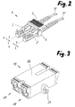
- the assembled plug arrangement 1 forms a compact, handy unit, the unlocking mechanism being able to be actuated with a single handle. As shown in FIG. 2, the two individual plugs 2 and 2 'can carry out slight relative movements in the arrow directions a and b. This is necessary for a stress-free insertion into the associated socket arrangement 19.
- such a bushing arrangement consists of the two bushes 20 and 20 ', which are integrally connected to one another via a material web 26.
- a fastening flange 25 is arranged on each side, on which the bushing arrangement can be fixed, for example on a housing wall.
- each plug side Pawl 21 there is a resilient on each plug side Pawl 21 arranged. When the final plug position is reached, this pawl snaps behind the locking bar 11 on the plug.
- a guide link 23 opens the protective flap 13 on the end face of the connector when plugged in, so that the plug pin 15 can penetrate into a centering sleeve 22.
- a resiliently mounted panel 24 is folded down.
- pressure is exerted on the handle 32 on the plug arrangement in the direction of arrow c (FIG. 4).
- the two swivel arms 12 and 12 'lift the pawls 21 assigned to the individual plugs via the locking strips 11 and the plug arrangement can be unplugged with a normal tensile force at which only the friction of the individual components has to be overcome.
- the unlocking lever 3 could also have a different configuration. Depending on the type of latching device, it could also be a lever, for example, which performs a linear movement instead of a pivoting movement.
- the additional connecting element would not necessarily have to be designed as a connecting clip. It could also be an element that engages the two connector housings in a different way. In certain cases, it would be conceivable to connect more than two plugs in the same way to form a plug arrangement on which the latching device can be released with a single unlocking lever.
- the connector housing, the release lever and the connecting element are preferably made of plastic material. A metal version would also be conceivable.
Abstract
Description
Die Erfindung betrifft eine Steckeranordnung bestehend aus wenigstens zwei optischen Steckern gemäss dem Oberbegriff von Anspruch 1. Diese sogenannten Duplex-Stecker werden dort eingesetzt, wo gleichzeitig zwei Lichtwellenleiter angeschlossen werden müssen. Für die Herstellung einer möglichst dämpfungsarmen Lichtübertragung an der Steckverbindung ist es dabei von grosser Bedeutung, dass die beiden einzelnen Stekker nicht völlig starr miteinander verbunden sind, sondern dass jeder Stecker in einem begrenzten Mass eine Relativbewegung ausführen kann.The invention relates to a connector arrangement consisting of at least two optical connectors according to the preamble of
Für Steckverbindungen des Push-Pull-Typs, die international unter der Typenbezeichnung SC genormt sind bestehen bereits verschiedene Varianten zum Verbinden von zwei Einzelsteckern zu einer Duplex-Steckeranordnung. Gemäss der WO-94/24 592 wird wenigstens eine Klammer auf die beiden Steckergehäuse aufgeschnappt, welche jedes Steckergehäuse einzeln erfasst und welche einen bogenförmigen Verbindungssteg zwischen den beiden Einzelklammern aufweist. Gemäss der US-A-5,123,071 besteht die Verbindung aus zwei Bügeln, die zusammengeschnappt werden können und welche die beiden Stecker zwischen sich klemmend erfassen. Es ist aber aus der EP-A-597 501 auch bereits bekannt, die beiden Steckergehäuse der Einzelstecker ohne zusätzliche Hilfsmittel unmittelbar miteinander zu verbinden.For push-pull type connectors, which are internationally standardized under the type designation SC, there are already different variants for connecting two single connectors to a duplex connector arrangement. According to WO-94/24 592, at least one clip is snapped onto the two connector housings, which detects each connector housing individually and which has an arcuate connecting web between the two individual clips. According to US-A-5,123,071, the connection consists of two brackets which can be snapped together and which grasp the two plugs between them. However, it is also already known from EP-A-597 501 to connect the two connector housings of the individual connectors directly to one another without additional aids.
Die Stecker des Push-Pull-Typs haben den Nachteil, dass eine Zugkraft auf das Steckergehäuse ausgeübt werden muss, um die Steckverbindung wieder zu lösen. Es sind zwar beispielsweise durch die EP-A-616 236 bereits Einzelstecker bekannt geworden, bei denen die Steckverbindung mit Hilfe eines Entriegelungshebels gelöst werden kann. Diese Stecker könnten zwar mit konventionellen Verbindungsklammern zu einer Duplex-Einheit verbunden werden, doch müsste dann jeder Entriegelungshebel einzeln betätigt werden. Es ist daher eine Aufgabe der Erfindung, eine Steckeranordnung der eingangs genannten Art zu schaffen, bei der die Steckerverriegelung in der Buchse ohne Zugkraft mit einem einzigen Handgriff gelöst werden kann. Diese Aufgabe wird erfindungsgemäss mit einer Steckeranordnung gelöst, welche die Merkmale in Anspruch 1 aufweist.The push-pull type plugs have the disadvantage that a tensile force must be exerted on the plug housing in order to release the plug connection again. Single plugs are already known, for example, from EP-A-616 236, in which the plug connection can be released with the aid of an unlocking lever. Although these plugs could be connected to a duplex unit using conventional connection clips, each release lever would then have to be can be operated individually. It is therefore an object of the invention to provide a connector arrangement of the type mentioned at the outset, in which the connector lock in the socket can be released in a single operation without pulling force. This object is achieved according to the invention with a plug arrangement which has the features in
Die beiden Einzelstecker sind mit einer Einrastvorrichtung versehen, welche nur mit einem Entriegelungshebel gelöst werden kann. Dieser Entriegelungshebel erfüllt jedoch eine Doppelfunktion, indem er auch noch als Verbindungseinrichtung zwischen den Steckern dient. Durch Betätigung des gemeinsamen Entriegelungshebels werden die Einrastvorrichtungen an den einzelnen Steckern simultan gelöst. Da der Entriegelungshebel an jedem Stecker beweglich gelagert ist, besteht trotzdem keine absolut starre Verbindung. Vorzugsweise ist der Entriegelungshebel ein Schwenkhebel, der an beiden Steckern um eine gemeinsame, im rechten Winkel zu den Steckerachsen verlaufende Achse schwenkbar gelagert ist. Die Montage wird dabei erleichtert, wenn der Schwenkhebel an jedem Stecker mit je zwei Gelenknocken gelagert ist. Denkbar wäre aber auch eine separate Achse, die sich durch beide Stecker erstreckt.The two single plugs are equipped with a locking device that can only be released with an unlocking lever. However, this unlocking lever fulfills a double function in that it also serves as a connecting device between the plugs. The locking devices on the individual plugs are released simultaneously by actuating the common unlocking lever. Since the release lever is movably mounted on each connector, there is still no absolutely rigid connection. The unlocking lever is preferably a pivoting lever which is pivotably mounted on both plugs about a common axis running at right angles to the plug axes. Installation is made easier if the swivel lever is mounted on each connector with two joint cams. A separate axis that extends through both plugs would also be conceivable.
Theoretisch genügt bereits der gemeinsame Schwenkhebel, um die beiden Einzelstecker so miteinander zu verbinden, dass sie stets paarweise in eine entsprechende Buchsenanordnung eingesteckt werden können. Zum Stabilisieren der Achsparallelität ist es jedoch besonders vorteilhaft, wenn die Verbindungseinrichtung ein zusätzliches Verbindungselement aufweist. Das zusätzliche Verbindungselement kann dabei eine Verbindungsklammer sein, welche auf Aufnahmeabschnitte an den beiden Steckern aufschnappbar ist.In theory, the common swivel lever is sufficient to connect the two individual plugs to one another so that they can always be inserted in pairs in a corresponding socket arrangement. To stabilize the axis parallelism, however, it is particularly advantageous if the connecting device has an additional connecting element. The additional connecting element can be a connecting clip, which can be snapped onto receiving sections on the two plugs.
Vorzugsweise hat die Verbindungsklammer zwei U-förmige Klammerabschnitte, wobei zwischen den Klammerabschnitten ein Distanzkörper angeordnet ist, der zwischen den beiden Steckern liegt. Dieser Distanzkörper dient zu einem gewissen Grad zum Parallelhalten der beiden Stecker. Anderseits verbessert er aber auch die Griffigkeit beim Anfassen der Steckeranordnung.The connecting clip preferably has two U-shaped clip sections, a spacer body being arranged between the clip sections, which is between the two plugs lies. This spacer serves to a certain extent to keep the two plugs parallel. On the other hand, it also improves grip when touching the connector arrangement.
Zur Erhöhung der Elastizität kann der Distanzkörper als Hohlkörper ausgebildet sein.To increase the elasticity, the spacer body can be designed as a hollow body.
Eine besonders vorteilhafte Anordnung ergibt sich, wenn die gemeinsame Schwenkachse des Entriegelungshebels auf der gleichen oder annähernd auf der gleichen Ebene liegt, wie die beiden Klammerabschnitte des Verbindungselements. Die Verbindungsklammer wird dabei auf der dem Entriegelungshebel entgegengesetzten Seite auf die Stecker aufgeschnappt. Wenn sich der Distanzkörper gegen die kabelseitige Endpartie der Stecker erstreckt ist ausserdem gewährleistet, dass bereits diese relativ flexible Endpartie, die normalerweise einen Knickschutz aufweist, parallel gehalten wird.A particularly advantageous arrangement results if the common pivot axis of the unlocking lever lies on the same or approximately the same level as the two clamp sections of the connecting element. The connecting clip is snapped onto the connector on the side opposite the unlocking lever. If the spacer body extends against the cable-side end part of the connector, it is also ensured that this relatively flexible end part, which normally has a kink protection, is held in parallel.
Weitere Vorteile und Einzelmerkmale der Erfindung ergeben sich aus der nachfolgenden Beschreibung eines Ausführungsbeispiels und aus den Zeichnungen. Es zeigen:Further advantages and individual features of the invention result from the following description of an exemplary embodiment and from the drawings. Show it:
- Figur 1Figure 1
- eine perspektivische Darstellung einer Steckeranordnung vor dem Zusammenbau,1 shows a perspective illustration of a plug arrangement before assembly,
- Figur 2Figure 2
- die Steckeranordnung gemäss Figur 1 im zusammengebauten Zustand,1 in the assembled state,
- Figur 3Figure 3
- eine Buchsenanordnung für die Steckeranordnung gemäss Figur 2,3 shows a socket arrangement for the plug arrangement according to FIG. 2,
- Figur 4Figure 4
- einen Längsschnitt durch die Steckeranordnung gemäss Figur 2, unda longitudinal section through the connector assembly according to Figure 2, and
- Figur 5Figure 5
- einen Längsschnitt durch die Buchsenanordnung gemäss Figur 3.3 shows a longitudinal section through the bushing arrangement according to FIG. 3.
Figur 1 zeigt insgesamt eine Steckeranordnung 1, bestehend aus den beiden Einzelsteckern 2 und 2', aus einem gemeinsamen Entriegelungshebel 3, der sich auf der Oberseite über beide Stecker erstreckt und aus einem Verbindungselement 6, das von unten auf die beiden Stecker geschnappt wird.Figure 1 shows a total of a
Weitere Einzelheiten über die Konstruktion der Stecker 2 und 2' ergeben sich aus Figur 4. Im übrigen wird auf die eingangs erwähnte EP-A-616 236 hingewiesen, welche diesen Typ der Einrastvorrichtung im Detail beschreibt. Im Steckergehäuse 17 ist ein Steckerstift 15 gelagert, der in Axialrichtung an einer Federanordnung 18 abgestützt ist. Das Lichtwellenleiterkabel 31 wird über einen Knickschutz 16 in das Steckergehäuse eingeführt und der hier nicht dargestellte Lichtwellenleiter ist im Steckerstift 15 zentrisch gefasst.Further details on the construction of the
Die Stirnseite des Steckers 2 ist mit einer Schutzklappe 13 abgedeckt. Diese Schutzklappe kann an einem Schutzklappenlager 14 aufgeschwenkt und zurückgezogen werden. Zur Verriegelung in der Buchse dient eine Sperrleiste 11, die in das Steckergehäuse integriert ist. Seitliche Lagerelemente 10 bilden eine Art Lagergabel zur Aufnahme des Entriegelungshebels 3.The end face of the
Der Entriegelungshebel 3 besteht aus einem Griffstück 32, das auf der Oberseite gerippt ist. Zwei separate Schwenkarme 12 und 12' sind so angeordnet, dass sie sich an jedem Stecker bis unmittelbar hinter die Sperrleite 11 erstrecken. Auf jeder Seite eines Schwenkarms ist je ein Gelenknocken 5 angeordnet. Diese Gelenknocken können in die Oeffnungen an den Lagerelementen 10 eingerastet werden. Der Entriegelungshebel 3 ist in der eingebauten Position um eine gemeinsame Achse 4 schwenkbar. Diese Achse verläuft im rechten Winkel zur Längsmittelachse der beiden Stecker 2 und 2'.The unlocking
Annähernd auf der gleichen vertikalen Ebene, auf welcher die gemeinsame Achse 4 liegt, ist jedes Steckergehäuse 17 auf der Aussenseite mit einem Aufnahmeabschnitt 7 versehen. Jeder Aufnahmeabschnitt ist dabei auf jeder Seite mit einer Leiste 29 versehen, welche parallel zur Steckerachse verläuft.Approximately on the same vertical plane on which the
An den Aufnahmeabschnitten 7 wird das zusätzliche Verbindungselement 6 aufgeschnappt. Dieses besteht im wesentlichen aus zwei U-förmigen Klammerabschnitten 8 und 8', zwischen denen ein Distanzkörper 9 angeordnet ist. Die Klammerabschnitte 8 sind an den oberen Enden der U-Schenkel mit angeschrägten Nocken 28 versehen. Diese Nocken rasten hinter den Leisten 29 an den Aufnahmeabschnitten 7 ein. Ein Hohlraum 30 erstreckt sich über die gesamte Länge des Distanzkörpers 9. Die Seitenwände des Distanzkörpers verlaufen etwas gekrümmt und sind damit dem Endabschnitt der beiden Stecker angepasst. Die Höhe des Distanzkörpers ist etwas grösser als der Durchmesser dieser Endabschnitte, wie insbesondere aus Figur 4 ersichtlich ist.The additional connecting
Die zusammengebaute Steckeranordnung 1 bildet eine kompakte, griffige Einheit, wobei der Entriegelungsmechanismum mit einem einzigen Handgriff betätigt werden kann. Wie in Figur 2 dargestellt ist, können die beiden Einzelstecker 2 und 2' in den Pfeilrichtungen a und b geringfügige Relativbewegungen ausführen. Dies ist für eine möglichst spannungsfreie Einführung in die dazugehörige Buchsenanordnung 19 erforderlich.The assembled
Gemäss Figur 3 besteht eine derartige Buchsenanordnung aus den beiden Buchsen 20 und 20', die über einen Materialsteg 26 einstückig miteinander verbunden sind. Auf jeder Seite ist je ein Befestigungsflansch 25 angeordnet, an dem die Buchsenanordnung beispielsweise an einer Gehäusewand fixiert werden kann.According to FIG. 3, such a bushing arrangement consists of the two
Einzelheiten einer Buchse 20 ergeben sich aus Figur 5, wobei diesbezüglich ebenfalls auf die EP-A-616 236 verwiesen wird.Details of a
Im Buchsengehäuse 27 ist auf jeder Steckerseite eine federnde Sperrklinke 21 angeordnet. Beim Erreichen der endgültigen Steckposition, rastet diese Sperrklinke hinter die Sperrleiste 11 am Stecker. Eine Führungskulisse 23 öffnet beim Einstecken die Schutzklappe 13 an der Stirnseite des Stekkers, so dass der Steckerstift 15 in eine Zentrierhülse 22 eindringen kann. Beim Einstecken wird eine federnd gelagerte Blende 24 nach unten geklappt. Zum Entriegeln der Einrastvorrichtung wird an der Steckeranordnung in Pfeilrichtung c (Figur 4) Druck auf das Griffstück 32 ausgeübt. Dabei heben die beiden Schwenkarme 12 und 12' die den einzelnen Steckern zugeordneten Sperrklinken 21 über die Sperrleisten 11 und die Steckeranordnung kann mit einer normalen Zugkraft ausgesteckt werden, bei der nur noch die Reibung der einzelnen Bauteile überwunden werden muss.In the
Selbstverständlich könnte der Entriegelungshebel 3 auch eine andere Konfiguration aufweisen. Je nach Art der Einrastvorrichtung könnte es sich beispielsweise auch um einen Hebel handeln, der anstelle einer Schwenkbewegung eine Linearebewegung ausführt. Auch das zusätzliche Verbindungselement müsste nicht unbedingt als Verbindungsklammer ausgebildet sein. Es könnte sich dabei auch um ein Element handeln, das auf andere Weise an den beiden Steckergehäuse angreift. In bestimmten Fällen wäre es denkbar, mehr als zwei Stecker auf die gleiche Art und Weise zu einer Steckeranordnung zu verbinden, an der die Einrastvorrichtung mit einem einzigen Entriegelungshebel gelöst werden kann. Die Steckergehäuse, der Entriegelungshebel und das Verbindungselement bestehen vorzugsweise aus Kunststoffmaterial. Auch eine Ausführung in Metall wäre aber denkbar.Of course, the unlocking
Claims (9)
Applications Claiming Priority (2)
| Application Number | Priority Date | Filing Date | Title |
|---|---|---|---|
| CH503/95 | 1995-02-21 | ||
| CH50395 | 1995-02-21 |
Publications (2)
| Publication Number | Publication Date |
|---|---|
| EP0729048A1 true EP0729048A1 (en) | 1996-08-28 |
| EP0729048B1 EP0729048B1 (en) | 1998-04-15 |
Family
ID=4188499
Family Applications (1)
| Application Number | Title | Priority Date | Filing Date |
|---|---|---|---|
| EP96810040A Expired - Lifetime EP0729048B1 (en) | 1995-02-21 | 1996-01-18 | Connector assembly consisting of at least two optical connectors |
Country Status (5)
| Country | Link |
|---|---|
| US (1) | US5675682A (en) |
| EP (1) | EP0729048B1 (en) |
| JP (1) | JPH08248267A (en) |
| AU (1) | AU696950B2 (en) |
| DE (1) | DE59600150D1 (en) |
Cited By (5)
| Publication number | Priority date | Publication date | Assignee | Title |
|---|---|---|---|---|
| EP0848267A2 (en) * | 1996-11-13 | 1998-06-17 | Molex Incorporated | Optical fiber connector assembly |
| DE19905244A1 (en) * | 1999-02-02 | 2000-08-24 | Siemens Ag | Optical connector holder for retaining one or more connector housings employing locking arms |
| EP1271204A1 (en) * | 2001-06-29 | 2003-01-02 | Diamond SA | Socket and plug for an optical connector |
| EP1275022B1 (en) * | 2000-04-18 | 2008-06-18 | ADC GmbH | Duplex connectors for optical fibre plug connectors |
| CN102598428A (en) * | 2009-09-10 | 2012-07-18 | 沃科莱特有限公司 | Break-away electrical connector |
Families Citing this family (58)
| Publication number | Priority date | Publication date | Assignee | Title |
|---|---|---|---|---|
| EP0838702B1 (en) * | 1996-10-28 | 2006-10-25 | Diamond SA | Connector for an optical connection |
| DE19728960C1 (en) * | 1997-06-30 | 2000-07-06 | Siemens Ag | Optical multiple connector |
| TW353523U (en) * | 1997-09-15 | 1999-02-21 | Conn Technology Inc U | Clamping device for single-head optical-fiber connector |
| JPH11174277A (en) * | 1997-12-12 | 1999-07-02 | Yazaki Corp | Optical connector |
| US6004043A (en) * | 1997-12-19 | 1999-12-21 | The Whitaker Corporation | Shuttered connector receptacle |
| US6024498A (en) * | 1998-02-05 | 2000-02-15 | Lucent Technologies Inc. | Optical fiber connector assembly |
| US6130977A (en) * | 1998-07-17 | 2000-10-10 | Siecor Operations, Llc | Fiber optic connector sleeve having positioning ribs |
| EP0982609B1 (en) * | 1998-08-21 | 2006-06-14 | Diamond SA | Sleeve for lightguide connection and connection |
| US6076974A (en) * | 1998-09-14 | 2000-06-20 | Lucent Technologies Inc. | Optical fiber connector |
| US6409392B1 (en) * | 1999-10-19 | 2002-06-25 | Fitel Usa Corp. | Duplex clip for clipping two optical fiber simplex connectors together to form a duplex connector |
| FR2804762B1 (en) * | 2000-02-08 | 2002-04-12 | France Telecom | FIXING SLEEVE FOR OPTICAL CABLES |
| DE50014409D1 (en) * | 2000-02-23 | 2007-07-26 | Diamond Sa | Plug part for a combined optical and electrical plug connection |
| US6419400B1 (en) * | 2000-04-07 | 2002-07-16 | Panduit Corp. | Fiber optic sleeve with drafted corner-wall sections |
| US6760530B1 (en) * | 2000-06-09 | 2004-07-06 | Cisco Technology, Inc. | Fiber cable connector clip |
| US6257917B1 (en) * | 2000-07-11 | 2001-07-10 | Itt Manufacturing Enterprises, Inc. | Connector latching arrangement |
| US8807843B2 (en) | 2000-07-17 | 2014-08-19 | Tyco Electronics Corporation | Connector system with physical security feature |
| US9625649B2 (en) | 2000-07-17 | 2017-04-18 | Commscope Technologies Llc | Connector system with physical security feature |
| US6758601B2 (en) * | 2001-09-28 | 2004-07-06 | Adc Telecommunications, In. | Fiberoptic connector and methods |
| DE60224877T2 (en) * | 2002-08-16 | 2008-05-15 | Agilent Technologies Inc., Santa Clara | An optical connector for coupling connectors to a multi-ported device |
| JP2004094109A (en) * | 2002-09-03 | 2004-03-25 | Furukawa Electric Co Ltd:The | Optical connector component |
| TW549463U (en) * | 2002-09-11 | 2003-08-21 | Hon Hai Prec Ind Co Ltd | Optical connector |
| CN100388028C (en) * | 2003-03-06 | 2008-05-14 | 蒂科电子公司 | Connector assembly clip |
| US6746145B1 (en) * | 2003-04-11 | 2004-06-08 | Wen-Chang Wu | Detachable lamp assembly device with detachable elements |
| US7660128B2 (en) * | 2004-09-30 | 2010-02-09 | Emcore Corporation | Apparatus for electrical and optical interconnection |
| US7373031B2 (en) * | 2004-09-30 | 2008-05-13 | Intel Corporation | Apparatus for an electro-optical device connection |
| US7234877B2 (en) * | 2004-10-27 | 2007-06-26 | Panduit Corp. | Fiber optic industrial connector |
| US7712979B2 (en) * | 2005-06-28 | 2010-05-11 | Sumiden High Precision Co., Ltd. | Optical adapter |
| US20070025666A1 (en) * | 2005-07-28 | 2007-02-01 | Sumiden High Precision Co., Ltd. | Optical connector plug |
| US7325980B2 (en) * | 2005-08-26 | 2008-02-05 | Tyco Electronics Corporation | Duplex style fiber optic connector interface assembly |
| US20080145005A1 (en) * | 2006-12-15 | 2008-06-19 | Masahiro Shibata | Optical communication module and optical sub-assembly |
| US8167638B2 (en) | 2007-06-12 | 2012-05-01 | Panduit Corp. | Multi-position quick release plug cassette assembly |
| US7632125B2 (en) * | 2007-08-17 | 2009-12-15 | Panduit Corp. | Plug locking assembly |
| GB2468188B (en) | 2009-02-26 | 2011-05-11 | Advanced Fiber Products Ltd | Fibre optic connector assembly |
| US8152385B2 (en) * | 2009-02-27 | 2012-04-10 | Corning Cable Systems Llc | Duplex fiber optic assemblies suitable for polarity reversal and methods therefor |
| US8241053B2 (en) * | 2009-09-10 | 2012-08-14 | Vocollect, Inc. | Electrical cable with strength member |
| US9366829B2 (en) * | 2010-03-16 | 2016-06-14 | Ofs Fitel, Llc | Multi-ferrule connector for multicore fiber terminations |
| US8753022B2 (en) | 2010-11-30 | 2014-06-17 | Adc Telecommunications, Inc. | LC connector and method of assembly |
| ES2395358B1 (en) | 2011-02-08 | 2014-04-25 | Tyco Electronics Corporation | SINGLE ACTION CONNECTOR |
| ES2402632B1 (en) | 2011-02-08 | 2014-05-14 | Tyco Electronics Raychem Bvba | RELEASE TONGUE FOR AN ELECTRICAL CONNECTOR AND ELECTRICAL CONNECTOR THAT INCLUDES SUCH RELEASE TONGUE |
| EP2705395B1 (en) | 2011-05-04 | 2020-01-08 | The Siemon Company | Fiber optic connector with polarity change |
| US8764308B2 (en) | 2011-06-06 | 2014-07-01 | Panduit Corp. | Duplex clip assembly for fiber optic connectors |
| US9291782B2 (en) * | 2011-07-01 | 2016-03-22 | Methode Electronics, Inc. | Multi-channel tranceiver module |
| US8814445B2 (en) * | 2011-08-23 | 2014-08-26 | Panduit Corp. | Apparatus and method for ganged multiple optical fiber connector |
| CN103257407B (en) | 2012-02-20 | 2015-11-25 | 泰科电子(上海)有限公司 | Connector and connector assembly |
| US9146362B2 (en) | 2012-09-21 | 2015-09-29 | Adc Telecommunications, Inc. | Insertion and removal tool for a fiber optic ferrule alignment sleeve |
| US9293862B2 (en) * | 2013-08-26 | 2016-03-22 | Panduit Corp. | Patch cord plug organizer |
| JP6318517B2 (en) * | 2013-09-24 | 2018-05-09 | オムロン株式会社 | Optical fiber unit for optical fiber sensor |
| EP3907541B1 (en) | 2014-01-13 | 2023-12-27 | CommScope Telecommunications (Shanghai) Co. Ltd. | Fiber optic connector |
| CN104808296B (en) * | 2014-01-28 | 2016-08-17 | 智英科技股份有限公司 | Duplex optical fiber connector plug |
| US20160154190A1 (en) * | 2014-01-28 | 2016-06-02 | Jyh Eng Technology Co., Ltd. | Duplex fiber optic connector plug |
| MX2017014377A (en) | 2015-05-15 | 2018-08-15 | Adc Telecommunications Shanghai Distrib Co Ltd | Alignment sleeve assembly and optical fibre adapter. |
| US9933584B2 (en) * | 2016-02-03 | 2018-04-03 | Jyh Eng Technology Co., Ltd. | Duplex fiber optic connector plug with angles actuated latching |
| US11215767B2 (en) | 2017-06-07 | 2022-01-04 | Commscope Technologies Llc | Fiber optic adapter and cassette |
| US10782481B1 (en) * | 2019-03-13 | 2020-09-22 | The Boeing Company | Optical fasteners having heads with lenses |
| US11220321B2 (en) | 2019-03-13 | 2022-01-11 | The Boeing Company | Window systems including optical fasteners |
| US11509095B2 (en) * | 2020-03-27 | 2022-11-22 | Panduit Corp. | Quick release plug pack assembly |
| US11747576B2 (en) * | 2020-12-29 | 2023-09-05 | Senko Advanced Components, Inc | Clip for holding fiber optic connectors |
| USD973593S1 (en) * | 2021-01-20 | 2022-12-27 | A.J. World Co., Ltd. | Housing for optical connector |
Citations (5)
| Publication number | Priority date | Publication date | Assignee | Title |
|---|---|---|---|---|
| US5123071A (en) | 1990-03-09 | 1992-06-16 | Amp Incorporated | Overconnector assembly for a pair of push-pull coupling type optical fiber connectors |
| US5268982A (en) * | 1992-06-29 | 1993-12-07 | The Whitaker Corporation | Friction detent duplex plug assembly |
| EP0597501A1 (en) | 1992-11-13 | 1994-05-18 | International Business Machines Corporation | Fiber optic connector housing |
| EP0616236A1 (en) | 1992-11-26 | 1994-09-21 | Diamond S.A. | Connector for a lightguide |
| WO1994024592A1 (en) | 1993-04-16 | 1994-10-27 | Alcoa Fujikura Ltd. | Flexible connector assembly for fiber optics |
Family Cites Families (7)
| Publication number | Priority date | Publication date | Assignee | Title |
|---|---|---|---|---|
| AU577099B2 (en) * | 1984-03-19 | 1988-09-15 | E.I. Du Pont De Nemours And Company | Receptacle, plug and optical connector |
| US5157749A (en) * | 1984-06-08 | 1992-10-20 | Amp Incorporated | High precision optical fiber connectors |
| JP2821301B2 (en) * | 1992-01-10 | 1998-11-05 | 日本電気株式会社 | Optical connector terminal structure |
| AU660859B2 (en) * | 1992-11-26 | 1995-07-06 | Diamond S.A. | Sleeve portion for an optical fibre plug connector |
| US5398295A (en) * | 1993-09-08 | 1995-03-14 | Chang; Peter C. | Duplex clip for optical fiber connector assembly |
| US5481634A (en) * | 1994-06-24 | 1996-01-02 | At&T Corp. | Connector for optical fiber |
| US5487123A (en) * | 1994-10-31 | 1996-01-23 | Delco Electronics Corporation | Connectors for optical fibers including resilient/expandable members |
-
1996
- 1996-01-18 EP EP96810040A patent/EP0729048B1/en not_active Expired - Lifetime
- 1996-01-18 DE DE59600150T patent/DE59600150D1/en not_active Expired - Lifetime
- 1996-01-23 AU AU42122/96A patent/AU696950B2/en not_active Expired
- 1996-01-30 US US08/594,317 patent/US5675682A/en not_active Expired - Lifetime
- 1996-02-20 JP JP8032259A patent/JPH08248267A/en active Pending
Patent Citations (5)
| Publication number | Priority date | Publication date | Assignee | Title |
|---|---|---|---|---|
| US5123071A (en) | 1990-03-09 | 1992-06-16 | Amp Incorporated | Overconnector assembly for a pair of push-pull coupling type optical fiber connectors |
| US5268982A (en) * | 1992-06-29 | 1993-12-07 | The Whitaker Corporation | Friction detent duplex plug assembly |
| EP0597501A1 (en) | 1992-11-13 | 1994-05-18 | International Business Machines Corporation | Fiber optic connector housing |
| EP0616236A1 (en) | 1992-11-26 | 1994-09-21 | Diamond S.A. | Connector for a lightguide |
| WO1994024592A1 (en) | 1993-04-16 | 1994-10-27 | Alcoa Fujikura Ltd. | Flexible connector assembly for fiber optics |
Cited By (11)
| Publication number | Priority date | Publication date | Assignee | Title |
|---|---|---|---|---|
| EP0848267A2 (en) * | 1996-11-13 | 1998-06-17 | Molex Incorporated | Optical fiber connector assembly |
| EP0848267A3 (en) * | 1996-11-13 | 1999-08-25 | Molex Incorporated | Optical fiber connector assembly |
| US6059461A (en) * | 1996-11-13 | 2000-05-09 | Molex Corporation | Optical fiber connector assembly |
| DE19905244A1 (en) * | 1999-02-02 | 2000-08-24 | Siemens Ag | Optical connector holder for retaining one or more connector housings employing locking arms |
| US6367987B1 (en) | 1999-02-02 | 2002-04-09 | Infineon Technologies Ag | Connector holder |
| DE19905244C2 (en) * | 1999-02-02 | 2002-09-19 | Infineon Technologies Ag | holder |
| EP1275022B1 (en) * | 2000-04-18 | 2008-06-18 | ADC GmbH | Duplex connectors for optical fibre plug connectors |
| EP1271204A1 (en) * | 2001-06-29 | 2003-01-02 | Diamond SA | Socket and plug for an optical connector |
| US6709165B2 (en) | 2001-06-29 | 2004-03-23 | Diamond Sa | Plug portion for an optical plug connection |
| CN102598428A (en) * | 2009-09-10 | 2012-07-18 | 沃科莱特有限公司 | Break-away electrical connector |
| CN102598428B (en) * | 2009-09-10 | 2015-04-22 | 沃科莱特有限公司 | Break-away electrical connector |
Also Published As
| Publication number | Publication date |
|---|---|
| DE59600150D1 (en) | 1998-05-20 |
| AU4212296A (en) | 1996-08-29 |
| EP0729048B1 (en) | 1998-04-15 |
| AU696950B2 (en) | 1998-09-24 |
| JPH08248267A (en) | 1996-09-27 |
| US5675682A (en) | 1997-10-07 |
Similar Documents
| Publication | Publication Date | Title |
|---|---|---|
| EP0729048B1 (en) | Connector assembly consisting of at least two optical connectors | |
| EP0616236B1 (en) | Connector for a lightguide | |
| DE69724011T2 (en) | OPTICAL CONNECTOR | |
| EP0599784A1 (en) | Socket for a fibre optic connection terminal | |
| WO2001059499A1 (en) | Optical connector for simultaneously connecting a plurality of fiber optical cables and adapter for said connector | |
| EP0838702B1 (en) | Connector for an optical connection | |
| WO2010063738A2 (en) | Intake device for a cable in an existing pipe network | |
| EP1509797A1 (en) | Optical plug-in connection | |
| EP1271204A1 (en) | Socket and plug for an optical connector | |
| DE3004390A1 (en) | HOUSING FOR ELECTRICAL LINE CONNECTIONS | |
| EP1364241A1 (en) | Fiber-optical connector system | |
| DE3539988A1 (en) | Locking device for plug connectors | |
| EP1095431A1 (en) | Electrical plug-in connector | |
| EP1252854B1 (en) | Tube connector for the suction tube of a vacuum cleaner | |
| EP1072918B1 (en) | Connector part for optical connection | |
| EP1320777A1 (en) | Coupling device for glass fiber connectors | |
| DE102019112612B3 (en) | Holding frame and connector with such a holding frame | |
| CH660238A5 (en) | COUPLING FOR LIGHTWAVE GUIDE. | |
| DE102010007581A1 (en) | Energy transmission chain for guiding of lines, hoses or cables, has individual chain links connected with each other, where one chain link is formed as cord grip chain link with cord grip | |
| EP1450186B1 (en) | Miniature multiple connector for optical fibres | |
| DE3640385C2 (en) | ||
| DE2829439C2 (en) | Vacuum cleaner with a suction hose on which a connection piece is provided | |
| BE1030843B1 (en) | Crimp adapter, crimp assembly and connector | |
| DE102006023712B4 (en) | Adapter arrangement for an electrical device | |
| WO2001018571A2 (en) | Optical plug-in connector |
Legal Events
| Date | Code | Title | Description |
|---|---|---|---|
| PUAI | Public reference made under article 153(3) epc to a published international application that has entered the european phase |
Free format text: ORIGINAL CODE: 0009012 |
|
| AK | Designated contracting states |
Kind code of ref document: A1 Designated state(s): CH DE FR GB IT LI NL |
|
| 17P | Request for examination filed |
Effective date: 19961021 |
|
| 17Q | First examination report despatched |
Effective date: 19961121 |
|
| GRAG | Despatch of communication of intention to grant |
Free format text: ORIGINAL CODE: EPIDOS AGRA |
|
| GRAG | Despatch of communication of intention to grant |
Free format text: ORIGINAL CODE: EPIDOS AGRA |
|
| GRAH | Despatch of communication of intention to grant a patent |
Free format text: ORIGINAL CODE: EPIDOS IGRA |
|
| GRAH | Despatch of communication of intention to grant a patent |
Free format text: ORIGINAL CODE: EPIDOS IGRA |
|
| GRAA | (expected) grant |
Free format text: ORIGINAL CODE: 0009210 |
|
| AK | Designated contracting states |
Kind code of ref document: B1 Designated state(s): CH DE FR GB IT LI NL |
|
| REG | Reference to a national code |
Ref country code: CH Ref legal event code: EP |
|
| REG | Reference to a national code |
Ref country code: CH Ref legal event code: NV Representative=s name: HEPP, WENGER & RYFFEL AG |
|
| REF | Corresponds to: |
Ref document number: 59600150 Country of ref document: DE Date of ref document: 19980520 |
|
| ET | Fr: translation filed | ||
| ITF | It: translation for a ep patent filed |
Owner name: LENZI & C. |
|
| GBT | Gb: translation of ep patent filed (gb section 77(6)(a)/1977) |
Effective date: 19980713 |
|
| PLBE | No opposition filed within time limit |
Free format text: ORIGINAL CODE: 0009261 |
|
| STAA | Information on the status of an ep patent application or granted ep patent |
Free format text: STATUS: NO OPPOSITION FILED WITHIN TIME LIMIT |
|
| 26N | No opposition filed | ||
| REG | Reference to a national code |
Ref country code: GB Ref legal event code: IF02 |
|
| REG | Reference to a national code |
Ref country code: FR Ref legal event code: PLFP Year of fee payment: 20 |
|
| PGFP | Annual fee paid to national office [announced via postgrant information from national office to epo] |
Ref country code: NL Payment date: 20150110 Year of fee payment: 20 |
|
| PGFP | Annual fee paid to national office [announced via postgrant information from national office to epo] |
Ref country code: CH Payment date: 20150324 Year of fee payment: 20 Ref country code: DE Payment date: 20150113 Year of fee payment: 20 Ref country code: IT Payment date: 20150116 Year of fee payment: 20 |
|
| PGFP | Annual fee paid to national office [announced via postgrant information from national office to epo] |
Ref country code: FR Payment date: 20150108 Year of fee payment: 20 Ref country code: GB Payment date: 20150114 Year of fee payment: 20 |
|
| REG | Reference to a national code |
Ref country code: DE Ref legal event code: R071 Ref document number: 59600150 Country of ref document: DE |
|
| REG | Reference to a national code |
Ref country code: NL Ref legal event code: MK Effective date: 20160117 |
|
| REG | Reference to a national code |
Ref country code: CH Ref legal event code: PL |
|
| REG | Reference to a national code |
Ref country code: GB Ref legal event code: PE20 Expiry date: 20160117 |
|
| PG25 | Lapsed in a contracting state [announced via postgrant information from national office to epo] |
Ref country code: GB Free format text: LAPSE BECAUSE OF EXPIRATION OF PROTECTION Effective date: 20160117 |