EP0730210B1 - Three dimensional coordinate measuring apparatus - Google Patents
Three dimensional coordinate measuring apparatus Download PDFInfo
- Publication number
- EP0730210B1 EP0730210B1 EP96301417A EP96301417A EP0730210B1 EP 0730210 B1 EP0730210 B1 EP 0730210B1 EP 96301417 A EP96301417 A EP 96301417A EP 96301417 A EP96301417 A EP 96301417A EP 0730210 B1 EP0730210 B1 EP 0730210B1
- Authority
- EP
- European Patent Office
- Prior art keywords
- measuring system
- probe
- arm
- housing
- transfer
- Prior art date
- Legal status (The legal status is an assumption and is not a legal conclusion. Google has not performed a legal analysis and makes no representation as to the accuracy of the status listed.)
- Expired - Lifetime
Links
Images


Classifications
-
- G—PHYSICS
- G01—MEASURING; TESTING
- G01B—MEASURING LENGTH, THICKNESS OR SIMILAR LINEAR DIMENSIONS; MEASURING ANGLES; MEASURING AREAS; MEASURING IRREGULARITIES OF SURFACES OR CONTOURS
- G01B5/00—Measuring arrangements characterised by the use of mechanical techniques
- G01B5/004—Measuring arrangements characterised by the use of mechanical techniques for measuring coordinates of points
- G01B5/008—Measuring arrangements characterised by the use of mechanical techniques for measuring coordinates of points using coordinate measuring machines
-
- G—PHYSICS
- G01—MEASURING; TESTING
- G01B—MEASURING LENGTH, THICKNESS OR SIMILAR LINEAR DIMENSIONS; MEASURING ANGLES; MEASURING AREAS; MEASURING IRREGULARITIES OF SURFACES OR CONTOURS
- G01B21/00—Measuring arrangements or details thereof, where the measuring technique is not covered by the other groups of this subclass, unspecified or not relevant
- G01B21/02—Measuring arrangements or details thereof, where the measuring technique is not covered by the other groups of this subclass, unspecified or not relevant for measuring length, width, or thickness
- G01B21/04—Measuring arrangements or details thereof, where the measuring technique is not covered by the other groups of this subclass, unspecified or not relevant for measuring length, width, or thickness by measuring coordinates of points
- G01B21/047—Accessories, e.g. for positioning, for tool-setting, for measuring probes
-
- G—PHYSICS
- G05—CONTROLLING; REGULATING
- G05B—CONTROL OR REGULATING SYSTEMS IN GENERAL; FUNCTIONAL ELEMENTS OF SUCH SYSTEMS; MONITORING OR TESTING ARRANGEMENTS FOR SUCH SYSTEMS OR ELEMENTS
- G05B19/00—Programme-control systems
- G05B19/02—Programme-control systems electric
- G05B19/18—Numerical control [NC], i.e. automatically operating machines, in particular machine tools, e.g. in a manufacturing environment, so as to execute positioning, movement or co-ordinated operations by means of programme data in numerical form
- G05B19/401—Numerical control [NC], i.e. automatically operating machines, in particular machine tools, e.g. in a manufacturing environment, so as to execute positioning, movement or co-ordinated operations by means of programme data in numerical form characterised by control arrangements for measuring, e.g. calibration and initialisation, measuring workpiece for machining purposes
-
- G—PHYSICS
- G05—CONTROLLING; REGULATING
- G05B—CONTROL OR REGULATING SYSTEMS IN GENERAL; FUNCTIONAL ELEMENTS OF SUCH SYSTEMS; MONITORING OR TESTING ARRANGEMENTS FOR SUCH SYSTEMS OR ELEMENTS
- G05B2219/00—Program-control systems
- G05B2219/30—Nc systems
- G05B2219/31—From computer integrated manufacturing till monitoring
- G05B2219/31174—Load, use different protocols, formats, emulators for different systems
-
- G—PHYSICS
- G05—CONTROLLING; REGULATING
- G05B—CONTROL OR REGULATING SYSTEMS IN GENERAL; FUNCTIONAL ELEMENTS OF SUCH SYSTEMS; MONITORING OR TESTING ARRANGEMENTS FOR SUCH SYSTEMS OR ELEMENTS
- G05B2219/00—Program-control systems
- G05B2219/30—Nc systems
- G05B2219/33—Director till display
- G05B2219/33192—Radio link, wireless
-
- G—PHYSICS
- G05—CONTROLLING; REGULATING
- G05B—CONTROL OR REGULATING SYSTEMS IN GENERAL; FUNCTIONAL ELEMENTS OF SUCH SYSTEMS; MONITORING OR TESTING ARRANGEMENTS FOR SUCH SYSTEMS OR ELEMENTS
- G05B2219/00—Program-control systems
- G05B2219/30—Nc systems
- G05B2219/34—Director, elements to supervisory
- G05B2219/34012—Smart, intelligent I-O coprocessor, programmable sensor interface
-
- G—PHYSICS
- G05—CONTROLLING; REGULATING
- G05B—CONTROL OR REGULATING SYSTEMS IN GENERAL; FUNCTIONAL ELEMENTS OF SUCH SYSTEMS; MONITORING OR TESTING ARRANGEMENTS FOR SUCH SYSTEMS OR ELEMENTS
- G05B2219/00—Program-control systems
- G05B2219/30—Nc systems
- G05B2219/37—Measurements
- G05B2219/37173—Encapsulate electronics of encoder in resin, electronics and encoder integrated
-
- G—PHYSICS
- G05—CONTROLLING; REGULATING
- G05B—CONTROL OR REGULATING SYSTEMS IN GENERAL; FUNCTIONAL ELEMENTS OF SUCH SYSTEMS; MONITORING OR TESTING ARRANGEMENTS FOR SUCH SYSTEMS OR ELEMENTS
- G05B2219/00—Program-control systems
- G05B2219/30—Nc systems
- G05B2219/37—Measurements
- G05B2219/37193—Multicoordinate measuring system, machine, cmm
-
- G—PHYSICS
- G05—CONTROLLING; REGULATING
- G05B—CONTROL OR REGULATING SYSTEMS IN GENERAL; FUNCTIONAL ELEMENTS OF SUCH SYSTEMS; MONITORING OR TESTING ARRANGEMENTS FOR SUCH SYSTEMS OR ELEMENTS
- G05B2219/00—Program-control systems
- G05B2219/30—Nc systems
- G05B2219/37—Measurements
- G05B2219/37213—Inhibit measuring if one of the joints is near endstop
-
- G—PHYSICS
- G05—CONTROLLING; REGULATING
- G05B—CONTROL OR REGULATING SYSTEMS IN GENERAL; FUNCTIONAL ELEMENTS OF SUCH SYSTEMS; MONITORING OR TESTING ARRANGEMENTS FOR SUCH SYSTEMS OR ELEMENTS
- G05B2219/00—Program-control systems
- G05B2219/30—Nc systems
- G05B2219/37—Measurements
- G05B2219/37357—Force, pressure, weight or deflection
-
- G—PHYSICS
- G05—CONTROLLING; REGULATING
- G05B—CONTROL OR REGULATING SYSTEMS IN GENERAL; FUNCTIONAL ELEMENTS OF SUCH SYSTEMS; MONITORING OR TESTING ARRANGEMENTS FOR SUCH SYSTEMS OR ELEMENTS
- G05B2219/00—Program-control systems
- G05B2219/30—Nc systems
- G05B2219/37—Measurements
- G05B2219/37405—Contact detection between workpiece and tool, probe, feeler
-
- G—PHYSICS
- G05—CONTROLLING; REGULATING
- G05B—CONTROL OR REGULATING SYSTEMS IN GENERAL; FUNCTIONAL ELEMENTS OF SUCH SYSTEMS; MONITORING OR TESTING ARRANGEMENTS FOR SUCH SYSTEMS OR ELEMENTS
- G05B2219/00—Program-control systems
- G05B2219/30—Nc systems
- G05B2219/37—Measurements
- G05B2219/37491—Compensate non linearity of transducer by lookup table
-
- G—PHYSICS
- G05—CONTROLLING; REGULATING
- G05B—CONTROL OR REGULATING SYSTEMS IN GENERAL; FUNCTIONAL ELEMENTS OF SUCH SYSTEMS; MONITORING OR TESTING ARRANGEMENTS FOR SUCH SYSTEMS OR ELEMENTS
- G05B2219/00—Program-control systems
- G05B2219/30—Nc systems
- G05B2219/39—Robotics, robotics to robotics hand
- G05B2219/39015—With different manipulator configurations, contact known sphere, ballbar
-
- G—PHYSICS
- G05—CONTROLLING; REGULATING
- G05B—CONTROL OR REGULATING SYSTEMS IN GENERAL; FUNCTIONAL ELEMENTS OF SUCH SYSTEMS; MONITORING OR TESTING ARRANGEMENTS FOR SUCH SYSTEMS OR ELEMENTS
- G05B2219/00—Program-control systems
- G05B2219/30—Nc systems
- G05B2219/39—Robotics, robotics to robotics hand
- G05B2219/39021—With probe, touch reference positions
-
- G—PHYSICS
- G05—CONTROLLING; REGULATING
- G05B—CONTROL OR REGULATING SYSTEMS IN GENERAL; FUNCTIONAL ELEMENTS OF SUCH SYSTEMS; MONITORING OR TESTING ARRANGEMENTS FOR SUCH SYSTEMS OR ELEMENTS
- G05B2219/00—Program-control systems
- G05B2219/30—Nc systems
- G05B2219/39—Robotics, robotics to robotics hand
- G05B2219/39414—7-DOF
-
- G—PHYSICS
- G05—CONTROLLING; REGULATING
- G05B—CONTROL OR REGULATING SYSTEMS IN GENERAL; FUNCTIONAL ELEMENTS OF SUCH SYSTEMS; MONITORING OR TESTING ARRANGEMENTS FOR SUCH SYSTEMS OR ELEMENTS
- G05B2219/00—Program-control systems
- G05B2219/30—Nc systems
- G05B2219/40—Robotics, robotics mapping to robotics vision
- G05B2219/40233—Portable robot
-
- G—PHYSICS
- G05—CONTROLLING; REGULATING
- G05B—CONTROL OR REGULATING SYSTEMS IN GENERAL; FUNCTIONAL ELEMENTS OF SUCH SYSTEMS; MONITORING OR TESTING ARRANGEMENTS FOR SUCH SYSTEMS OR ELEMENTS
- G05B2219/00—Program-control systems
- G05B2219/30—Nc systems
- G05B2219/40—Robotics, robotics mapping to robotics vision
- G05B2219/40596—Encoder in each joint
-
- G—PHYSICS
- G05—CONTROLLING; REGULATING
- G05B—CONTROL OR REGULATING SYSTEMS IN GENERAL; FUNCTIONAL ELEMENTS OF SUCH SYSTEMS; MONITORING OR TESTING ARRANGEMENTS FOR SUCH SYSTEMS OR ELEMENTS
- G05B2219/00—Program-control systems
- G05B2219/30—Nc systems
- G05B2219/45—Nc applications
- G05B2219/45061—Measuring robot
-
- G—PHYSICS
- G05—CONTROLLING; REGULATING
- G05B—CONTROL OR REGULATING SYSTEMS IN GENERAL; FUNCTIONAL ELEMENTS OF SUCH SYSTEMS; MONITORING OR TESTING ARRANGEMENTS FOR SUCH SYSTEMS OR ELEMENTS
- G05B2219/00—Program-control systems
- G05B2219/30—Nc systems
- G05B2219/49—Nc machine tool, till multiple
- G05B2219/49206—Compensation temperature, thermal displacement, use measured temperature
-
- G—PHYSICS
- G05—CONTROLLING; REGULATING
- G05B—CONTROL OR REGULATING SYSTEMS IN GENERAL; FUNCTIONAL ELEMENTS OF SUCH SYSTEMS; MONITORING OR TESTING ARRANGEMENTS FOR SUCH SYSTEMS OR ELEMENTS
- G05B2219/00—Program-control systems
- G05B2219/30—Nc systems
- G05B2219/49—Nc machine tool, till multiple
- G05B2219/49298—Probe identification
-
- G—PHYSICS
- G05—CONTROLLING; REGULATING
- G05B—CONTROL OR REGULATING SYSTEMS IN GENERAL; FUNCTIONAL ELEMENTS OF SUCH SYSTEMS; MONITORING OR TESTING ARRANGEMENTS FOR SUCH SYSTEMS OR ELEMENTS
- G05B2219/00—Program-control systems
- G05B2219/30—Nc systems
- G05B2219/50—Machine tool, machine tool null till machine tool work handling
- G05B2219/50042—Return to origin, reference point, zero point, homing
-
- G—PHYSICS
- G05—CONTROLLING; REGULATING
- G05B—CONTROL OR REGULATING SYSTEMS IN GENERAL; FUNCTIONAL ELEMENTS OF SUCH SYSTEMS; MONITORING OR TESTING ARRANGEMENTS FOR SUCH SYSTEMS OR ELEMENTS
- G05B2219/00—Program-control systems
- G05B2219/30—Nc systems
- G05B2219/50—Machine tool, machine tool null till machine tool work handling
- G05B2219/50252—Replace, change tool with tracer head, probe, feeler
Definitions
- This invention relates generally to three dimensional coordinate measuring machines (or CMM's). More particularly, this invention relates to a new and improved three dimensional CMM which is portable and provides improved accuracy and ease of use.
- Position in a space may be defined by length, width and height which, in engineering terms, is often called an X, Y, Z coordinate.
- the X, Y, Z numbers represent the dimensions of length, width and height or three dimensions.
- Three-dimensional objects are described in terms of position and orientation; that is, not just where an object is but in what direction it points.
- the orientation of an object in space can be defined by the position of three points on the object. Orientation can also be described by the angles of alignment of the object in space.
- the X, Y, and Z coordinates can be most simply measured by three linear scales. In other words, if you lay a scale along the length, width and height of a space, you can measure the position of a point in the space.
- CMM's measure objects in a space using three linear scales. These devices are typically non-portable, expensive and limited in the size or volume that can be easily measured.
- FARO Technologies, Inc. of Lake Mary, Florida has successfully produced a series of electrogoniometer-type digitizing devices for the medical field.
- FARO Technologies, Inc. has produced systems for skeletal analysis known as METRECOM® and systems for use in surgical applications knwon as SURGICOMTM.
- Electrogoniometer-type devices of the type embodied in the METRECOM and SURGICOM systems are disclosed in U.S. Patent 4,670,851, 5,251,127 and 5,305,203, all of which are assigned to the assignee hereof and incorporated herein by reference.
- Prior art document GB2275339A describes a three dimensional coordinate measuring apparatus. The manually positionable arm of this coordinate measuring apparatus possesses five or six degrees of freedom.
- a novel, portable coordinate measuring machine comprises a multijointed (seven joints) manually positionable measuring arm for accurately and easily measuring a volume as claimed in claim 1.
- a sphere preferably ranging from six to twelve feet in diameter (but which may also cover diameters more or less than this range) and a measuring accuracy of preferably 2 Sigma +/- 0.0003 inch (and optimally 2 Sigma +/- 0.001 inch).
- the present invention preferably employs a controller (or serial box) which acts as the electronic interface between the arm and a host computer.
- the mechanical measuring arm used in the CMM of this invention is generally comprised of a plurality of transfer housings (with each transfer housing comprising a joint and defining one degree of rotational freedom) and extension members attached to each other with adjacent transfer housings being disposed at right angles to define a movable arm having seven degrees of freedom.
- Each transfer housing includes measurement transducers and preferably novel bearing arrangements. These novel hearing arrangements include prestressed bearings formed of counter-positioned conical roller bearings and stiffening thrust bearings or alternatively, standard duplex bearings for high bending stiffness with a low profile structure.
- each transfer casing preferably includes physical visual and audio endstop indicators to protect against mechanical overload due to mechanical stressing.
- the movable arm is attached to a base or post which preferably includes (1) a temperature monitoring board for monitoring temperature stability; (2) an encoder mounting plate for universal encoder selection; (3) an EEPROM circuit board containing calibration and identification data so as to avoid unit mixup; and (4) a preamplifier board mounted near the encoder mounting plate for transmission of high amplified signals to a remote counter board in the controller.
- the transfer casings are modular permitting variable assembly configurations and the entire movable arm assembly is preferably constructed of one material for ensuring consistent coefficient of thermal expansion (CTE).
- CTE coefficient of thermal expansion
- this invention preferably includes a spring counterbalanced and shock absorbed support mechanism for user comfort and a two switch (take/accept) data entry device for allowing high precision measurements with manual handling.
- a generalized option of the type used in the prior art METRECOM system is provided for the measurement of variables in three dimensions (e.g., temperature may be measured in three dimensions using a thermocouple attached to the option port).
- a discrete microprocessor-based controller box is an important feature of certain embodiments this invention as it permits preprocessing of specific or integrated controller calculations without host level processing requirements. This is accomplished by mounting an intelligent preprocessor in the controller box which provides programmable adaptability and compatibility with a variety of external hosts (e.g., external computers).
- the serial box also provides intelligent multi-protocol evaluation and autoswitching by sensing communication requirements from the host. For example, a host computer running software from one manufacturer will generate call requests of one form-which are automatically sensed by the controller box.
- Still other features of the controller box include serial port communications for standardized long distance communications in a variety or industrial environments and novel analog-to-digital/digital counter boards for simultaneous capture of every encoder (located in the transfer housing) resulting in highly accurate measurements.
- the CMM of this invention preferably includes means for performing a volummetric accuracy measurement protocol on an interim basis, preferably using a novel cone ballbar device.
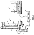
- the three dimensional measuring system of the present invention generally comprises a coordinate measuring machine (CMM) 10 composed of a manually operated multijointed arm 12 and a support base or post 14, a controller or serial box 16 and a host computer 18. It will be appreciated that CMM 10 electronically communicates with serial box 16 which, in turn, electronically communicates with host computer 18.
- CMM coordinate measuring machine
- CMM 10 includes transducers (e.g., one transducer for each degree of freedom) which gather rotational positioning data and forward this basic data to serial box 16.
- Serial box 16 provides a reduction in the overall requirements of host computer 18 to handle certain complex calculations and provides certain preliminary data manipulations.
- serial box 16 is intended to be positioned under the host computer 18 (such as the notebook computer shown in FIGURE 2) and includes EEPROMS which contain data handling software, a microcomputer processor, a signal processing board and a number of indicator lights 20.
- basic transducer data is sent from CMM 10 to serial box 16.
- Serial box 16 then processes the raw transducer data on an ongoing basis and responds to the queries of the host computer with the desired three-dimensional positional or orientational information.
- all three components defining the three dimensional measuring system of this invention are mounted on either a fixed mounting surface using a rigid plate and/or a standard optical measurement instrument thread followed by mounting on a known and standard theodolite mobile stand such as shown at 22 in FIGURE 3.
- theodolite stand 22 comprises a part no. MWS750 manufactured by Brunson.
- Such a mobile stand is characterized by a stable rolling platform with an extendable vertical tower and with common attachments and locking mechanisms.
- support base 14 of CMM 10 is threaded or otherwise attached onto a vertical support member 24 of stand 22 while serial box 16/host 18 is supported on a shelf 26 pivotally connected at a first joint 28 to an arm 30 which is pivotally connected to a second joint 32.
- Connecting member 34 interconnects joint 32 to a swivel connection 36 attached to a cap 38 mounted over the top of member 24.
- CMM 10 comprises a base 14 connected to a first set of two transfer housings including a first transfer housing 40 which, in turn, is connected to a second transfer housing 42 (positioned transverse to housing 40).
- a first extension member 44 is rigidly attached to a second set of two transfer housings including a third transfer housing 46 transversely attached to a fourth transfer housing 48.
- First extension member 44 is positioned perpendicularly between transfer housings 42 and 46.
- a second extension member 50 is aligned with an rigidly attached to transfer housing 48.
- Rigid extension member 50 is rigidly attached to a third set of two transfer housings including a fifth transfer housing 52 transversely attached to a sixth transfer housing 54.
- Fifth transfer housing 54 has attached thereto a handle/probe assembly 56. This CMM with only 6 degrees of freedom is outside the scope of this invention.
- position sensing transducers are mounted in each of the six transfer housings 40, 42, 46, 48, 52 and 54.
- Each housing is comprised of bearing supports and transducer compartments which are made to then cylindrically attach to each other using 45" angled attachment screws (FIGURE 6).
- At the base 14 is a counterbalanced spring device 60 for support of arm 12 in its standard vertical configuration (FIGURE 8).
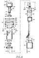
- FIGURE 6 is an exploded view of a transfer housing
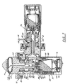
- FIGURE 7 shows an enlarged view of the transversely oriented and attached transfer housings (e.g., housings 46 and 48).
- Each housing includes an internal carrier 62 and an external casing 64.
- Mechanical stability between internal carrier 62 and external casing 64 is provided by two counter-positioned (e.g., oppositely disposed) conical roller bearings 66, 68 positioned to compress against their respective conical races, 70, 72.
- Conical races 70 and 72 are permanently affixed into the external transfer casing 64.
- Carrier includes a shaft 122 extending therefrom and terminating at threading 74.
- Conical bearings 66, 69 are preferably made from hardened steel while races 70, 72 are also made from hardened steel.
- Thrust bearing 76 provides further mechanical stiffening between carrier 62 and casing 64 of the transfer housing. Thrust bearing 76 comprises five elements including thrust adjustment ring 300, flat annular race 302, roller bearing and cage 304, annular race 306 and opposing thrust cover 308.
- Thrust bearing 76 is adjusted through a series of set screws 78 and provides for high bending stiffness.
- the transducer (preferably an encoder 80 such as is available from Heindenhain under the designation Mini-Rod, part no. 450M-03600), is mounted to a universal mounting plate 82 for mounting into the transfer casing.
- Universal mounting plate 82 is important in satisfying possible component availability problems such that a change in manufacture of transducer 80 and, hence, the change in mounting screw configuration can be accommodated through modifications in the mounting plate 82.
- Mounting plate 82 is shown in FIGURE 6A as a triangular shaped plate having rounded corners.
- FIGURE 6A also depicts threaded members 88 and 90, a pin 86 and a coupler 84 (all of which are discussed hereinafter).
- Coupler 84 such as is available from Renbrandt under the designation B1004R51R.
- An extension shaft 86 is utilized for ultimately connecting encoder 80 to the transfer casing 64. Shaft 86 is attached both to coupler 84 and to the end of carrier 62 at threading 74 using set screws 88, 90 (see FIGURE 7).
- an electronic preamplifier board 92 is positioned in close proximity to encoder 80 and is mounted (via screws 94) on the inside of cap cover 96.
- Cap cover 96 is attached to casing 64 via screw 97.
- a transition housing 98 interconnects cap cover 96 to casing 64 via screw 97 and screws 100. Sealing of the transfer housing to the environment is accomplished at the joint using an O-ring groove 102 in which is mounted a standard rubber O-ring groove 104.
- a rotational endstop 106 (to be discussed hereinafter), is best shown in FIGURE 6B and comprises a square shaped metal housing having an opening therethrough which is mounted onto casing 64 using bolt 108 threaded through the opening of the housing.
- Wire pass through grommets to stop abrasion over long term use are mounted on both carrier 62 and casing 64 at 110 and 112.
- a location pin 114 is received by a complimentary shaped recess 116 in carrier 62 for the purpose of maintaining relative orientation of two adjacent transfer casings.
- FIGURE 7 depicts two assembled transfer housings 46, 48 mounted perpendicularly to each other and demonstrating the passage of wires.
- the encoder information from encoder 80 is passed to its processor board 92 through wire 118 which is then amplified and passed through the arm by machined passageways 120.
- Wire 118 then passes through a channel 120 in the shaft 122 of the internal carrier 62 of the transfer casing 46 and through a grommetted hole 124 at which time it passes into a large cavity 126 machined on the external casing 64 of transfer housing 46.
- Cavity 126 permits the coiling of the wire strands during rotation of tlie transfer casing and is configured so as not to produce any wire abrasion and a minimum of wire bending. However, because the wire limits the overall ability to fully rotate, an incomplete spherical groove 128 is created in which is positioned an endstop screw, 130 which limits the full rotation, in this case to 330°.
- a second preferred alternative end stop design which permits 660° of rotation will be discussed hereinafter after the first preferred embodiment is fully described herein for reasons of clarity. It will he appreciated that the pass through channel 120 and wire coiling cavities 122 are subsequently repeated in each transfer casing allowing the wires to progressively make their way down to the connector mounted at the base 14, resulting in no exposed wiring.
- FIGURE 8 the construction of the aluminum arm as well as the various bearings and transducers results in an accumulated weight of approximately 10 to 15 pounds at the probe handle assembly 56 of CMM 10. Under normal circumstances, this would create a significant amount of fatigue during use and, hence, must be counterbalanced. Weight counterbalances are not preferred since they would significantly increase the overall weight of the device when being considered for transportability. Therefore, in a preferred embodiment counterbalancing is performed using counterbalance device 60 which comprises a torsional spring 132 housed in a plastic casing 134 and mounted at transfer housing 42 at base 14 for providing a lift for arm 12.
- Coiled torsional spring 132 can be mounted in a variety of positions affecting the overall pretension and, hence, may be usable on a variety of lengths and weights of arms 12. Similarly, due to the weight of arm 12 and the effect of the recoiled spring, significant shock loads may occur when repositioning the arm to the storage position. To prevent significant shocking of the arm upon retraction, air piston shock absorber 134 is also configured into plastic housing 142 of counterbalance spring device 60. This results in an absorption of the shock load and slow relaxation into the rest position. It will be appreciated that FIGURE 8 depicts the shock absorber 134 in a depressed configuration while FIGURES 16-18 depict shock absorber 134 in a fully extended position.
- Probe handle assembly 56 is meant to be held as either a pencil or pistol grip and possesses two switches (items 150 and 152 in FIGURE 9A) for data taking, a connector (item 154 in FIGURE 9B) for the attachment of optional electronics and a threaded mount 156 for receiving a variety of probes, Because the CMM 19 is a manual measurement device, the user must he capable of taking a measurement and then confirming to CMM 10 whether the measurement is acceptable or not. This is accomplished through the use of the two switches 150, 152. The front switch 150 is used trap the 3-dimensional data information and the back switch 152 confirms its acceptance and transmits it to the host computer 18. On the back of the switch enclosure 158 (housing 150, 152) is connector 154 which possesses a number of voltage lines and analog-to-digital converter lines for general attachment to a number of options such as a laser scanning device or touch probe.
- FIGURE 10A hard 1/4 inch diameter ball probe 158 is shown while in FIGURE 10B, a point probe 160 is shown. Both probes 158, 160 are threadably mounted to mount 156 (using male threaded member 157), which in turn, is threadably mounted to probe housing 58. Mount 156 also includes a plurality of flat surfaces 159 for facilitating engagement and disengagement of the probes using a wrench.
- FIGURE 11 shows the front panel face 162 of the controller or serial box 16.
- Front panel 162 has eight lights including power indicator light 164, error condition light 166, and six lights 20, one for each of the six transducers (identified as items 1-6) located in each transfer housing.
- power light 164 will indicate power to the arm 12.
- all transducer lights will indicate the status of each of the transducers.
- the transducers are incremental digital optical encoders 80 and require referencing. (In a less preferred embodiment, the transducers may be analog devices).
- each of the joints e.g., transfer housings
- each of the joints must be rotated to find the reference position at which time the lights shall turn off.
- a light and an audible beep for that particular transducer indicates to the user that the user is too close to the end stop; and that the orientation of the arm should be readjusted for the current measurement.
- the serial box 16 will continue to measure but will not permit the trapping of the data until such endstop condition is removed.
- a typical situation where this endstop feature is necessary is the loss of a degree of freedom by the rotation of a particular transducer to its endstop limit and, hence, the applications of forces on the arm causing unmeasured deflections and inaccuracies in the measurement.
- front panel 162 may alternatively utilize an alphanumeric LCD panel giving alphanumeric error and endstop warnings.
- the rear panel 168 of serial box 16 includes a variety of standard PC connectors and switches including a reset button 170 which resets the microprocessor; an AC input fan 172 for air circulation; a connector 174 for a standard PC AT keyboard, connector 176 for an optional VGA board for monitoring of the internal operations of serial box 16, connector 178 for receiving the variety of signal lines for the CMM data, and connector 180 for the standard RS232 connector for the host 18.
- Serial box 16 is responsible for monitoring the temperature of the CMM and in real time modifying the kinematics or mathematics describing its motion according to formulas describing the expansion and contraction of the various components due to changes in temperature.
- a temperature monitoring board 182 (which includes a temperature transducer) is positioned at the location of the second joint 42 on the interior of a cover 184 (see FIGURES 4 and 5).
- CMM 10 is preferably constructed of aircraft grade aluminum externally and anodized.
- the entire arm 12 is constructed of the same material except for the mounting screws which are stainless steel. The same material is used throughout in order to make uniform the expansion and contraction characteristics of arm 12 and make it more amenable to electronic compensation.
- the temperature transducer 182 is preferably located at transfer housing 42 because it is believed that this location defines the area of highest mass and is therefore the last area to be stabilized after a large temperature fluctuation.
- FIGURE 13 the preferred overall electronic schematic layout for CMM 10 and serial box 16 is shown.
- Six encoders 80 are shown with each encoder having an amplifier board 92 located in close proximity to it for the minimization of noise on signal transfer.
- An option port 154 is shown which is a six pin connector available at the handle 56 for the attachment of a variety of options.
- Two control buttons 150 and 152 for indicating to serial box 16 the measurement process, are also shown.
- the temperature transducer is associated with a temperature circuit board 182 which is also located in arm 12 as shown in FIGURE 13.
- the temperature board 182 comprises an EEPROM board.
- the EEPROM is a small computerized memory device (electrically erasable programmable read only memory) and is used to contain a variety of specific calibration and serial number data on the arm (see discussion regarding FIGURES 19-21). This is an especially preferred feature of this invention which permits high quality control of CMM 10 and importantly, precludes the inadvertent mixup of software and arms. This also means that the CMM arm 12 is a stand alone device not requiring specific calibration data to reside in controller box 16 which may need to be separately serviced and/or switched with other machines.
- the electronic and pulse data from the arm electronics is then transmitted to a combined analog-to-digital converter/digital counting board 186 which is a paired set comprising a 12 bit analog to digital converter and a multi channel 16 bit digital counter.
- Board 186 is positioned on the standard buss of the controller box.
- the counting information is processed using the core module 188 (comprising a commercially available Intel 286 microprocessor such as a part number CMX-286-Q51 available from Ampro) and programs stored on an EEPROM also residing in the controller box. Subsequent data is then transmitted through the serial communication port 189.
- the microprocessor-based serial box 16 permits preprocessing of calculations specific to CMM 10 without host level processing requirements.
- Typical examples of such preprocessor calculations include coordinate system transformations; conversion of units; leap-frogging from one coordinate system to another by using an intermediary jig; performance of certain certification procedures, including calculations of distance between 2 balls (such as in ANSI B89 ballbar); and outputting data in specific formats required for downloading to a variety of hosts and user programs.
- the serial box is configured to communicate with a variety of host formats including PC, MSDOS, Windows, Unix, Apple, VME and others.
- the serial box processes the raw transducer data on an ongoing basis and responds to the information requests or polling of the host computer with the desired three dimensional positional or orientational information.
- the language of the serial box is in such a form that drivers or computer communication subroutines in microprocessor 188 are written in the language of the host computer so as to drive the serial port and communicate with CMM 10.
- This function is designated the "intelligent multi-protocol emulation and autoswitching" function and works as follows: A variety of host programs may be installed on the host computer. These host programs will poll the serial port with a variety of requests to which the serial box must respond.
- a number of protocols have been preprogrammed into the serial box to respond to polls or inquiries on the serial port for a variety of different, popular softwares.
- a polling request by a software requires a specific response.
- the serial box will receive the polling request, establish which protocol it belongs to, and respond in the appropriate manner.
- This allows transparent communication between CMM 10 and a wide variety of application software such as computer aided design and quality control softwares, e.g., AutoCad® from Autodesk, Inc., CADKEY® from Cadkey, Inc., and other CAD programs; as well as quality control programs such as GEOMET® from Geomet Systems, Inc. and Micromeasure III from Brown and Sharpe, Inc.
- the three dimensional CMM of the present invention operates as follows. Upon power up, the microprocessor 188 in the serial box 16 undergoes start up self-checking procedures and supplies power through the instrument port to arm 12 of CMM 10. The microprocessor and software residing on EEPROM 182 determines that upon initial power up none of the encoders 80 have been initialized. Hence, the microprocessor 188 sends a signal to the display board lighting all the lights 20, indicating a need to be referenced. The user will then mechanically move the arm which will cause the transducers to individually scan their range, at which time a reference mark is passed.
- the digital counter board 186 responds by trapping its location and identifying to the front display board 20 that the transducer has been referenced and the light is extinguished. Once all transducers have been referenced, the system establishes serial communication with the host and waits for further instruction. Pressing of the front or back button of handle 56 will initiate a measurement process. Pressing the front button 150 will trap the current transducer readings. Pressing the back button 152 will indicate to the microprocessor that these values are to be translated into dimensional coordinates and issued through the serial port to the host 18. The host 18 and the serial box 16 will then continue to react to each other's serial line requests.
- This initial calibration is an important feature of this invention and is accomplished in two stages. First, a variety of dimensional measurements are made which include positions, orientations and dimensions throughout the entire volume of the device. Subsequently, an optimization software program is used to determine the actual misalignments exiting at each of the joint axes and, hence, adjusting the kinematic formulas describing the motion of the arm. The general result is that imperfect machining and assembly is rendered perfect through the identification of those imperfections and their inclusion in the kinematics of the device.
- Jig 320 is comprised of a large granite plate 322 to which is attached two spaced towers 324, 326 which can rotate 360 degrees in the horizontal plane.
- the CMM 10 is mounted on tower 326 and the adjustable dimensional testing jig 320 is mounted on the other tower 324.
- Jig 320 is mounted on an extendable vertical arm 328 which is vertically displaceable within an opening 330 through tower 324. Arm 328 is shown in a fully extended position.
- the adjustable dimensional testing jig 320 is comprised of three basic components: a 24 inch bar 332 on which is found a set of precision balls 334, a series of holes 336 positioned along its length, and a 24 inch precision step gauge 338 (shown in detail in FIGURES 20A-E) Arm 332 is used to measure the positions of the holes, steps and balls in a variety of positions for the testing jig and in all areas of the volume of the arm as shown in FIGURE 21. This data is then optimized. In summary, the important optimization procedure can be described as follows. Standard test jig 320 with predetermined positions and orientations of objects is measured by arm 10.
- the data is then processed through a multi-variable optimization program created to provide the relative misalignment and dimension of all major components of the arm. Optimization is performed, at which time a calibration file is produced containing the overall characteristics of the arm. These overall characteristics and subsequent transducer readings are combined in a variety of kinematic formulas which will generate the X, Y and Z values in an absolute coordinate system.
- a novel reference ball 192 extends laterally from a detachable mount 194 attached to base 14 of CMM 10 (see FIGURES 14 and IS).
- ball 92 represents the absolute origin of the device (0, 0, 0) corresponding to the X, Y and Z axes.
- positioning of the tips allows the present invention to determine the coordinates of the digitizer tip 158 in relationship to the last link of CMM 10. Knowledge of this position allows CMM 10 to determine the position of the center of that ball when making subsequent measurements. In a general sense, this means that a variety of different probes may then be attached depending on the particular application and each can be calibrated against the reference ball.
- the present invention preferably includes a protocol by which the user may establish a degree of volummetric accuracy prior to using a device according to a convenient maintenance schedule.
- Volummetric accuracy is defined, according to ASME ANSI B891.1.12 (1989) standard, as the ability of a device to measure a fixed length which is positioned in its working volume in a variety of orientations.
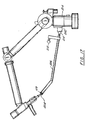
- FIGURE 16 shows the capability of this invention to do this using a first ballbar approach while FIGURES 17 and 18 depict a second ballbar approach.
- FIGURE 16 shows a standard ballbar 196 at each end of which is positioned a precision spherical ball 198, 200 which are mounted respectively into two magnetic sockets 202 and 204.
- Socket 202 is located at base 14 of CMM 10 and socket 204 is located at probe handle 56.
- the sockets 202, 204 and balls 198, 200 rotate to accommodate this movement and CMM 10 is required to measure the fixed distance between the center of ball 200 and socket 204 at the handle 56 and the center of ball 198 at the base.
- socket 202 at base 14 represents the 0, 0, 0 coordinate of CMM 10
- calibration software in control box 16 then calculates the vector length from the 0, 0, 0 to the center of the ball at the probe and this length, which, of course, is unchanging during the test, must measure constantly throughout the entire volume through multiple configurations and rotations of the handle and other joints.
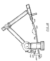
- Cone socket ballbar 206 includes a cone 208 at one end and two balls 210, 212 at the other end.
- the cone and balls arc interconnected by a bar 207 having an angled portion 209 with then angle ⁇ preferably comprising 20 degrees.
- Ball 212 is attached to a mount 211 which extends laterally from bar 207.
- a ball probe 58 or point probe 160 is positioned in cone socket 208 and ball 210 can be mounted in the standard magnetic socket 202 of base 14 of CMM 10.
- a number of positions of the ball and bar and joint positions are measured and the distance between cone socket 208 and ball 210 must remain constant. It is the nature of the positioning of ball socket 202 that the user will not be able to reach on the far side of the machine (position shown by Item 214).
- ball 212 is used as shown in FIGURE 18. This allows the user to position cone ballbar 206 so as to reach on the reverse far side of CMM 10 in order to measure the distance between the center of ball 212 and the center of cone socket 208.
- strut supports are preferably provided which are mounted at the one end to threaded holes aimed radially outward from the base loading plate and at the second end arc fitted with universal clamps (i.e., C-clamps).
- the strut support is provided with an adjustment screw to adjust the length of the strut to properly reach the measured item.
- the strut is intended to be used in pairs preferably by means of an identical strut on the opposite side of the base loading plate.
- the base 14 of the measuring arm 10 is mounted into base plate 38 of a theodolite stand 22 or other suitable rigid plate in a known manner.
- Base plate 38 has threaded holes 400 of a suitable known size extending outwardly in at least two places directly opposite each other.
- Strut 402 is generally comprised of four elements. There are two arm elements 404, an adjustment screw 406 and a universal clamp 408 (i.e., C-clamps) as shown.
- C-clamps universal clamp 408
- any number of adaptable attachment devices could be used such as magnetic clamps and suction clamps.
- an item 410 to be measured by the three dimensional measuring arm 10 is mounted to a second mounting plate 412 or is otherwise rigidly fixed.
- both base plates 38 and 412 are held rigidly in relation to one another and instability is reduced to an absolute minimum.
- FIGURES 23A-C are diagrammatic representations of degrees of freedom allowed in CMM 10 with the representation shown in Figure 23C being within the scope of this invention.
- the support base 14 allows two degrees of freedom as indicated by the rotational arrows 421 and 422.
- CMM 10 may be compared to the arm configuration of the human body as consisting of elements such as a shoulder which would be equivalent to support base 14,
- the elbow element, 444, 50 is the equivalent of the elbow of the human arm and the handle/probe assembly 56 is equivalent to the human wrist.
- the design FIGURE 23A which is outside the scope of the invention, has two degrees of freedom represented at the shoulder, elbow and wrist (designated 2-2-2) and is more easily able to probe into difficult to reach areas.
- the FIGURE 23B design which is also outside the scope of the invention, has two degrees of freedom at the shoulder, one degree of freedom at the elbow and three degrees of freedom at the wrist and has the following advantages.
- FIGURE 23A the two degrees of freedom of the elbow are designated by the rotational arrows 424, 426 and finally the two degrees of freedom at wrist (or effect element) assembly 56 are designated by the rotational arrows 428, 430.
- FIGURE 23B the one degree of freedom of the elbow segment is designated by the rotational arrows 432 and the three degrees of freedom at the wrist assembly by the arrows, 434, 436, and 438.
- FIGURE 23C the three degrees of freedom of the wrist segment are designated by the rotational arrows 444, 446 and 448.
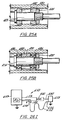
- FIGURES 24A and 24B are diagrammatic representations of two preferred means in accordance with the present invention for interconnection of the signal paths between the CMM 10 (coordinate measuring machine), or controller or serial box 16 and the host computer 18.
- CMM 10 is electronically connected to serial box 16 by known cabling means 460 and again serial box 16 is connected by known cabling means 462 to host computer 18.
- This method of interconnecting the CMM 10, controller or serial box 16 and the host computer 18 is and has proven quite satisfactory for innumerable applications of the present invention.
- Miniaturized serial box 464 includes a telemetry device 466 which is provided with means capable of transmitting telemetry signals 468 which are received by a telemetry receiver 470 mounted on host computer 18.
- a telemetry receiver 470 mounted on host computer 18.
- FIGURES 25A and 25B depict two preferred bearing designs.
- the bearing design of FIGURE 25A has hereinbefore been described in complete detail as depicted in FIGURES 6 and 7.
- a pair of counter positioned layered bearings with inner race 480 and outer race 482 are positioned around a shaft and preloaded using a nut 484.
- the preloading is determined entirely by the amount of torque applied to the nut 484.
- This design is quite satisfactory for many applications and has been used with considerable success. However, under certain conditions and applications it is difficult to maintain consistent loading parameters.
- a second preferred alternative embodiment of the bearing design is provided in accordance with the present invention.
- FIGURE 25B This second preferred alternative embodiment of the bearing design is depicted in FIGURE 25B.
- a pair of bearings (usually called duplex bearings) 486 which are usually radial ball bearings and which are preground to permit very specific preloading replace the conical bearings of FIGURE 25A.
- the preloading is preset by the of fixed spacers 488, 490 and these fixed spacers 498, 490 are tightened down completely by a nut 492.
- the difference between the duplex bearing casing are accommodated and the amount of preload is predetermined by deformations in the transfer casing at the time of tightening nut 492.
- An advantageous feature of this second preferred embodiment is that the nut 492 can be tightened as much as possible without any damage of overloading the bearings 486 along the shaft 494.
- FIGURES 9A-B are front and rear side elevation views of probe handle assembly 56.
- an adapter 500 is fitted onto the end effector of probe handle assembly 506.
- Probe 508 which is either of a different size and/or configuration has a relatively longer depth bore 510 and the bore is designated as 572. Both probes 502 and 508 have a male thread 514 sized to match the female thread 516 at the end of adapter 500. Because of the dirty and rigorous environment of the industrial applications in which it is necessary and desirable to use these probes, the use of electrical contacts are often too problematic.
- a probing shaft 518 extends downwardly from a transducer 520 which in turn is connected to the internal circuitry through wiring 522 which connects the probe signal to the rest of the CMM 10 through the probe handle assembly 56.
- probing shaft 518 is of a slightly smaller diameter than the bores 504, 512.
- Arrow 524 represents the axial motion of probing shaft 518.
- FIGURES 26D and 26E another embodiment of a probe in accordance with the present invention is generally shown at 530.
- Marking probe 530 is comprised of mounting system 532, a clamp 534 and a marking pen 536.
- Mounting stem 532 has a shank 538 which is suitably sized to enter a bore 540 for either a press fit into bore 540, or may be welded or otherwise suitably fastened to clamp 534.
- the other end of shank 538 of mounting stem 532 has a suitably sized male thread 542 to be threaded into the female bore 544 of the probe handle assembly 56.
- FIGURE 26E is a cross-section of clamps 534 taken along line 26E-26E at the center line of marking pen tightening set screw 546.
- marking probe 530 can be used with a wide variety of marking implements to create highly accurate lines and/or other operations with the benefit of the inherent accuracy of the CMM 10 of this present invention.
- FIGURE 26F A third additional preferred embodiment of a probe in accordance with the present invention is shown in FIGURE 26F and is generally shown at 560.
- Automatic punch probe 560 is comprised of a standard recoil punch probe.
- the mounting portion 562 of punch probe 560 has a male thread 564 which is sized to be threaded into female thread 566 of probe handle assembly 56.
- automatic punch probe 560 contains a recoil spring and trigger assembly 568 which allows the positioning of the punch point 570 along the axial direction as shown by arrows 572.
- this force sensing probe may be equipped with a variety of end tips (ball tip, points tip, flat bottom tips, etc.) which are attached to probe body 582.
- the force sensing probe is generally shown at 580.
- a spherical end tip 584 is shown in FIGURE 26G.
- a male mounting thread 586 which is sized to threadably attach to female thread 588 of probe handle assembly 56.
- the force sensitive probe 580 has internally mounted strain gauges 590 preferably of the readily available and known standard resistive type (such as those manufactured by Omega Engineering, Inc.
- strain gauge technology is well-established and known in the art. While there is a variety of other methodologies for measuring strain, experience in the art has demonstrated that the methodology discussed herein is the preferred methodology.
- FIGURE 26H depicts a fifth additional preferred embodiment of a probe in accordance with the present invention, this probe being known as a drill mounting probe.
- the drill mounting probe is generally shown at 600.
- Drill mounting probe 600 is compromised of mounting stem 602, body 604 and rotary assembly and shaft 606 laterally displaced from mounting stem 602.
- Mounting stem 602 is sized at one end to be installed via press fitting into base 608.
- mounting stem 602 has a male thread 610 at its upper end sized to fit the female mounting thread 612 of probe handle assembly 56.
- Rotary assembly 606 is comprised of a shaft 614, an assembly nut 620, a pair of bearings 616 and chuck 618.
- Shaft 614 is sized at one end to be received by the chuck of a standard drill or other rotary portable power source 622 known to the industry.
- Body 604 is substantially of rectangular shape and is sized to adequately support the rotary power source described above and is preferably made of aluminum. Assembly nut 620, shaft 614, the pair of bearings 616 and chuck 618 can be assembled in any number of known ways.
- the bearings 616 are preferably of the ball bearing type.
- Chuck 618 is sized to handle any desired size drill bit or other tool (i.e., countersink, etc.).
- the rotary direction of the drill is the same as the direction of the power source 622 as shown by rotary arrow 624 shown between power source 622 and rotary assembly 606 and rotary arrow 626 shown below drill bit 628.
- the resulting holes or other operations again, with the use of the discussed probe, are within the high accuracy limits of CMM 10.
- a sixth additional preferred embodiment of a probe in accordance with the present invention is known as a contact probe and is depicted schematically in FIGURE 261 and generally shown at 650.
- a cable 652 is connected at one end through a connector 654 to the option port 154 of the probe handle assembly 56.
- the other end of cable 652 is terminated in an alligator clip or other suitable termination 656 to make contact with the metallic object 658 to be measured or other desired functions to be performed.
- a voltage is applied to cable 652. Grounding occurs as a result of contact by the end probe 660 (shown in solid lines when retracted and dotted lines when extended) contact with the object 658.
- the voltage V drops to the potential of ground and the software in the analog to digital converter (A to D) 659 has been designated to consider the grounding of cable 652 through the A to D device to be identical to the actuation of the buttons 150, 152 of the probe handle assembly 56.
- This option port 154 is connected through the cable 652 and the termination 656 to the object 658 which is metallic or conductive. In this manner, the probe 660 is grounded when probe 660 comes into contact with the conductive object 658. Grounding the cable 652 and reducing the voltage V to ground level results in a grounding signal being sent through the A to D device and software to actuate the probe handle assembly 56.
- a further advantageous feature of this contact probe 650 of the present invention is that because the contact switch actuation occurs at the first instance of the probe tip 660 touching the object 658, any additional or subsequent movement involving the object 658 are obviated or precluded and the initial measurements are therefore clear of any extraneous impulses.
- FIGURES 27A-27E a transfer case set is shown schematically at 700.
- FIGURE 28A is a top view of the arch shaped shuttle and
- FIGURE 28B is a side elevation view of the arc shaped shuttle used in this second preferred design that allows a full 660° of rotation in any set of transfer cases of the present invention.
- Matching channels are machined to a suitable depth in the shoulder of the transfer case shaft and the mating shoulder of the transfer case housing sized to accommodate the shuttle 701 (see FIGURES 29A and 28B).
- shuttle 702 is preferably .246" in height and the inside radius is preferably 1.042 and the outside radius is preferably 1.187" with the length of shuttle 702 representing a 20° arc at these radii shuttle 702 is made preferably of plastic material.
- X arc represents the 30° stop arc in transfer case housing shoulder and Y represents the 30° stop arc in the transfer case shaft shoulder.
- Groove 504 in the transfer case housing is sized to accominodate one half of the elevation height of shuttle 702 and suitably finished so that the shuttle 702 freely travels in the groove 704 of the transfer casing housing (see FIGURE 27B) and the groove 706 of the transfer case shaft (see FIGURE 27C).
- Shuttle 702 is depicted by cross-hatching in FIGURES 27B-27E.
- shuttle groove is free to travel from the P position adjacent to the X stop segment in FIGURE 2713 (representing the shuttle groove in the transfer case shoulder housing) and the P position adjacent to the Y stop segment in FIGURE 27C (representing the shuttle groove in the transfer case shaft shoulder) 330° to the P1 position adjacent to the X stop segment in FIGURE 27B and the P1 position adjacent to the Y stop segment in FIGURE 27C.
- shuttle 702 is now rigidly fixed between segment Y and segment X as seen in FIGURE 27D after counter clockwise rotation of 330°.
- the transfer case assembly is thus allowed to rotate an additional 330° in a clockwise direction.
- the shuttle 702 is designed to have a shear strength to protect the elements of the CMM 10 from deformation should the arm be moved beyond the 660° provided by this invention as a safety precaution. Not shown is a window slot provided for easy replacement of the shuttle 702.
Description
- This invention relates generally to three dimensional coordinate measuring machines (or CMM's). More particularly, this invention relates to a new and improved three dimensional CMM which is portable and provides improved accuracy and ease of use.
- It will be appreciated that everything in the physical world occupies volume or space. Position in a space may be defined by length, width and height which, in engineering terms, is often called an X, Y, Z coordinate. The X, Y, Z numbers represent the dimensions of length, width and height or three dimensions. Three-dimensional objects are described in terms of position and orientation; that is, not just where an object is but in what direction it points. The orientation of an object in space can be defined by the position of three points on the object. Orientation can also be described by the angles of alignment of the object in space. The X, Y, and Z coordinates can be most simply measured by three linear scales. In other words, if you lay a scale along the length, width and height of a space, you can measure the position of a point in the space.
- Presently, coordinate measurement machines or CMM's measure objects in a space using three linear scales. These devices are typically non-portable, expensive and limited in the size or volume that can be easily measured.
- FARO Technologies, Inc. of Lake Mary, Florida (the assignee of the present invention) has successfully produced a series of electrogoniometer-type digitizing devices for the medical field. In particular, FARO Technologies, Inc. has produced systems for skeletal analysis known as METRECOM® and systems for use in surgical applications knwon as SURGICOM™. Electrogoniometer-type devices of the type embodied in the METRECOM and SURGICOM systems are disclosed in U.S. Patent 4,670,851, 5,251,127 and 5,305,203, all of which are assigned to the assignee hereof and incorporated herein by reference.
Prior art document GB2275339A describes a three dimensional coordinate measuring apparatus. The manually positionable arm of this coordinate measuring apparatus possesses five or six degrees of freedom. - While well suited for their intended purposes, the METRECOM and SURGICOM electrogoniometer-type digitizing systems arc not well suited for general industrial applications where three dimensional measurements of parts and assemblies are often required. Therefore, there is a continuing need for improved, accurate and low cost CMM's for industrial and related applications.
- The above-discussed and other problems and deficiencies of the prior art are overcome or alleviated by the three dimensional measuring instrument (e.g., electrogoniometer) of the present invention. In accordance with the present invention, a novel, portable coordinate measuring machine comprises a multijointed (seven joints) manually positionable measuring arm for accurately and easily measuring a volume as claimed in
claim 1. In a preferred embodiment, it comprises a sphere preferably ranging from six to twelve feet in diameter (but which may also cover diameters more or less than this range) and a measuring accuracy of preferably 2 Sigma +/- 0.0003 inch (and optimally 2 Sigma +/- 0.001 inch). In addition to the measuring arm, the present invention preferably employs a controller (or serial box) which acts as the electronic interface between the arm and a host computer. - The mechanical measuring arm used in the CMM of this invention is generally comprised of a plurality of transfer housings (with each transfer housing comprising a joint and defining one degree of rotational freedom) and extension members attached to each other with adjacent transfer housings being disposed at right angles to define a movable arm having seven degrees of freedom. Each transfer housing includes measurement transducers and preferably novel bearing arrangements. These novel hearing arrangements include prestressed bearings formed of counter-positioned conical roller bearings and stiffening thrust bearings or alternatively, standard duplex bearings for high bending stiffness with a low profile structure. In addition, each transfer casing preferably includes physical visual and audio endstop indicators to protect against mechanical overload due to mechanical stressing.
- The movable arm is attached to a base or post which preferably includes (1) a temperature monitoring board for monitoring temperature stability; (2) an encoder mounting plate for universal encoder selection; (3) an EEPROM circuit board containing calibration and identification data so as to avoid unit mixup; and (4) a preamplifier board mounted near the encoder mounting plate for transmission of high amplified signals to a remote counter board in the controller.
- As in the prior art METRECOM system, the transfer casings are modular permitting variable assembly configurations and the entire movable arm assembly is preferably constructed of one material for ensuring consistent coefficient of thermal expansion (CTE). Similarly as in the METRECOM system, preferably internal wire routing with rotation stops and wire coiling cavities permit complete enclosure of large numbers of wires. Also consistent with the prior art METRECOM system, this invention preferably includes a spring counterbalanced and shock absorbed support mechanism for user comfort and a two switch (take/accept) data entry device for allowing high precision measurements with manual handling. Also, a generalized option of the type used in the prior art METRECOM system is provided for the measurement of variables in three dimensions (e.g., temperature may be measured in three dimensions using a thermocouple attached to the option port).
- The use of a discrete microprocessor-based controller box is an important feature of certain embodiments this invention as it permits preprocessing of specific or integrated controller calculations without host level processing requirements. This is accomplished by mounting an intelligent preprocessor in the controller box which provides programmable adaptability and compatibility with a variety of external hosts (e.g., external computers). The serial box also provides intelligent multi-protocol evaluation and autoswitching by sensing communication requirements from the host. For example, a host computer running software from one manufacturer will generate call requests of one form-which are automatically sensed by the controller box. Still other features of the controller box include serial port communications for standardized long distance communications in a variety or industrial environments and novel analog-to-digital/digital counter boards for simultaneous capture of every encoder (located in the transfer housing) resulting in highly accurate measurements.
- Efficient on-site calibration of the CMM of the present invention is preferably improved through the use of a reference hall positioned at the base of the CMM to obviate potential mounting complications to system accuracy evaluation. In addition, the CMM of this invention preferably includes means for performing a volummetric accuracy measurement protocol on an interim basis, preferably using a novel cone ballbar device.
- The above-discussed and other features and advantages of the present invention will be appreciated and understood by those skilled in the art from the following detailed description and drawings.
- Referring to the drawings, wherein like elements are numbered alike in the several FIGURES:
- FIGURE 1 is a front diagrammatic view depicting the three dimensional measuring system of the present invention including a coordinate measuring machine, a controller box and a host computer;
- FIGURE 2 is a side elevation view depicting the host computer mounted on the serial box, which is in turn, mounted on a maneuverable arm;
- FIGURE 3 is a side elevation view of the three dimensional measuring system of the present invention mounted on a theodolite stand;
- FIGURE 4 is a rear elevation view of the CMM shown in FIGURE 1;
- FIGURE 5 is a longitudinal view, partly in cross-section of the CMM of FIGURE 1;
- FIGURE 6 is an exploded, side elevation view of a transfer housing used in the CMM of FIGURE 1;
- FIGURES 6A and 6B are views along the
lines 6A-6A and 6B-6B, respectively, of FIGURE 6; - FIGURE 7 is a cross-sectional elevation view of two assembled, transversely orientated transfer housings;
- FIGURE 8 is an enlarged, side elevation view of a counterbalanced spring device used in the CMM of FIGURE 1;
- FIGURES 9A and 9B are top and bottom plan views depicting the handle/probe assembly of FIGURE 1;
- FIGURES 10A and 10B are respective side elevation views of a ball probe and a point probe;
- FIGURE 11 is an enlarged front view of the controller box of FIGURE 1;
- FIGURE 12 is an enlarged rear view of the controller box of FIGURE 1;
- FIGURE 13 is a schematic view of the electronic components for the three dimensional measuring system of FIGURE 1;
- FIGURE 14 is a side elevation view of the CMM of FIGURE 1 depicting a probe tip calibration system;
- FIGURE 15 is a schematic top plan view showing a method of calibrating the probe tip;
- FIGURE 16 is a side elevation view of the CMM of FIGURE 1 being calibrated with a ballbar;
- FIGURES 17 and 18 arc side elevation views of the CMM of FIGURE 1 being calibrated by a novel cone ballbar device;
- FIGURE 19 is a side elevation view depicting a method for optimizing the CMM of FIGURE 1 using an optimization jig;
- FIGURES 20A-E are respective front, rear, top, right side and left side elevation views of the precision step gauge used in the jig of FIGURE 19;
- FIGURE 21 is a schematic view showing a method of optimizing the CMM or FIGURE 1 utilizing the apparatus of FIGURE 19;
- FIGURE 22 is a diagrammatic front elevation view of the measuring arm of the present invention depicting strut supports for stability between the measuring arm and the object being measured;
- FIGURE 23A is a diagrammatic front elevation view of the measuring arm outside the scope of the present invention representing an embodiment of the six degrees of freedom in a 2-2-2 configuration;
- FIGURE 23B is a diagrammatic front elevation view of the measuring arm outside the scope of the present invention representing an embodiment of the six degrees of freedom in a 2-1-3 configuration;
- FIGURE 23C is a diagrammatic front elevation view of the measuring arm of the present invention representing a preferred embodiment of the seven degrees of freedom in a 2-2-3 configuration;
- FIGURE 24A is a front diagrammatic view of the CMM of FIGURE 1 with the CMM, serial box and host computer interconnected with cables;
- FIGURE 24B is a front diagrammatic view of an alternative CMM where the serial box circuitry has been miniaturized and mounted directly to the side (or base) the measuring arm and where both the serial box and host computer can send and receive signals by telemetry;
- FIGURES 25A and 25B are a cross-sectional elevation views along the center line of a portion of the transfer housing of FIGURE 6 depicting a preferred alternative hearing designs of the present invention;
- FIGURE 26 A and 26B are respective side elevation views, partially in cross-section, of two different probes fitted with machined holes of different depth for receiving a probing shaft for automatic identification of the correct probe;
- FIGURE 26C is a center line cross section elevation view of a transducer probe shaft mount capable of automatic sensing of the machined hole depth of the probes of FIGURES 26A and 26B;
- FIGURE 26D is a front elevation view of a marking pen probe with the probe mount shown partially in cross-section in accordance with the present invention;
- FIGURE 26E is a cross sectional view along the
line 26E-26E of FIGURE 26D; - FIGURE 26F is a front elevation view, partially in cross section of an automatic punch probe in accordance with the present invention;
- FIGURE 26G is a front elevation view, partially in cross section of a force sensing probe in accordance with the present invention;
- FIGURE 26H is a front elevation view, partially in cross section of a drill mounting probe in accordance with the present invention;
- FIGURE 261 is a diagrammatic elevation view of a contact probe which makes a measurement upon grounding in accordance with the present invention;
- FIGURE 27A is a partial diagrammatic view partly in cross section of a second preferred alternative stop arrangement of the transfer housing and shaft that permits 660° of rotation at each freedom of movement in the CMM in accordance with the present invention;
- FIGURE 27B is a cross-sectional view along the
line 27B-27B of FIGURE 27A before rotation; - FIGURE 27C is a cross-sectional view along the line 27C-27C of FIGURE 27A before rotation;
- FIGURE 27D is a cross-sectional view along the
line 27D-27D of FIGURE 27A after counterclockwise rotation of 330°; - FIGURE 27E is a cross-sectional view along the
line 27E-27E of FIGURE 27A after clockwise rotation of 330°; - FIGURE 28A is a top plan view of a shuttle in accordance with the present invention; and
- FIGURE 28B is a front elevation view of a shuttle in accordance with the present invention.
-
- Referring first to FIGURE 1, the three dimensional measuring system of the present invention generally comprises a coordinate measuring machine (CMM) 10 composed of a manually operated
multijointed arm 12 and a support base or post 14, a controller orserial box 16 and ahost computer 18. It will be appreciated thatCMM 10 electronically communicates withserial box 16 which, in turn, electronically communicates withhost computer 18. - As will be discussed in more detail hereinafter,
CMM 10 includes transducers (e.g., one transducer for each degree of freedom) which gather rotational positioning data and forward this basic data toserial box 16.Serial box 16 provides a reduction in the overall requirements ofhost computer 18 to handle certain complex calculations and provides certain preliminary data manipulations. As shown in FIGURE 2,serial box 16 is intended to be positioned under the host computer 18 (such as the notebook computer shown in FIGURE 2) and includes EEPROMS which contain data handling software, a microcomputer processor, a signal processing board and a number of indicator lights 20. As mentioned, basic transducer data is sent fromCMM 10 toserial box 16.Serial box 16 then processes the raw transducer data on an ongoing basis and responds to the queries of the host computer with the desired three-dimensional positional or orientational information. - Preferably, all three components defining the three dimensional measuring system of this invention (e.g.,
CMM 10,serial box 16 and host computer 18) are mounted on either a fixed mounting surface using a rigid plate and/or a standard optical measurement instrument thread followed by mounting on a known and standard theodolite mobile stand such as shown at 22 in FIGURE 3. Preferably, theodolite stand 22 comprises a part no. MWS750 manufactured by Brunson. Such a mobile stand is characterized by a stable rolling platform with an extendable vertical tower and with common attachments and locking mechanisms. As shown in FIGURES 2 and 3,support base 14 ofCMM 10 is threaded or otherwise attached onto avertical support member 24 ofstand 22 whileserial box 16/host 18 is supported on a shelf 26 pivotally connected at a first joint 28 to anarm 30 which is pivotally connected to a second joint 32. Connectingmember 34 interconnects joint 32 to aswivel connection 36 attached to acap 38 mounted over the top ofmember 24. - Referring now to FIGURES 1 and 4-9,
CMM 10 will now be described in detail. As best shown in FIGURE 5,CMM 10 comprises a base 14 connected to a first set of two transfer housings including afirst transfer housing 40 which, in turn, is connected to a second transfer housing 42 (positioned transverse to housing 40). Afirst extension member 44 is rigidly attached to a second set of two transfer housings including athird transfer housing 46 transversely attached to afourth transfer housing 48.First extension member 44 is positioned perpendicularly betweentransfer housings second extension member 50 is aligned with an rigidly attached to transferhousing 48.Rigid extension member 50 is rigidly attached to a third set of two transfer housings including afifth transfer housing 52 transversely attached to asixth transfer housing 54.Fifth transfer housing 54 has attached thereto a handle/probe assembly 56. This CMM with only 6 degrees of freedom is outside the scope of this invention. - In general (and as will he discussed in more detail hereinafter), position sensing transducers are mounted in each of the six
transfer housings base 14 is acounterbalanced spring device 60 for support ofarm 12 in its standard vertical configuration (FIGURE 8). - Turning now to FIGURES 6 and 7, a detailed description will be made of a transfer housing and its internal components. It will be appreciated that FIGURE 6 is an exploded view of a transfer housing, while FIGURE 7 shows an enlarged view of the transversely oriented and attached transfer housings (e.g.,
housings 46 and 48). Each housing includes aninternal carrier 62 and anexternal casing 64. Mechanical stability betweeninternal carrier 62 andexternal casing 64 is provided by two counter-positioned (e.g., oppositely disposed)conical roller bearings Conical races external transfer casing 64. Carrier includes ashaft 122 extending therefrom and terminating at threading 74.Conical bearings 66, 69 are preferably made from hardened steel whileraces - A second preferred alternative bearing arrangement will he discussed hereinafter after the first preferred embodiment is fully described herein for reasons of clarity.
- During assembly of
transfer casing 48, a compressional force is applied using anut 73, which is tightened to a specific torque onthreads 74, providing a prestressed bearing situation resulting in no motion other than axial rotation under typically applied loads. Because of the necessity of a low profiled or such an arm during manual handling and the attendant reduction in the overall stiffness, it is preferable and, in fact required in certain applications, to also install athrust bearing 76 at the interface betweencarrier 62 andcasing 64.Thrust bearing 76 provides further mechanical stiffening betweencarrier 62 andcasing 64 of the transfer housing.Thrust bearing 76 comprises five elements includingthrust adjustment ring 300, flatannular race 302, roller bearing and cage 304,annular race 306 and opposingthrust cover 308.Thrust bearing 76 is adjusted through a series ofset screws 78 and provides for high bending stiffness. The transducer, (preferably anencoder 80 such as is available from Heindenhain under the designation Mini-Rod, part no. 450M-03600), is mounted to auniversal mounting plate 82 for mounting into the transfer casing. Universal mountingplate 82 is important in satisfying possible component availability problems such that a change in manufacture oftransducer 80 and, hence, the change in mounting screw configuration can be accommodated through modifications in the mountingplate 82. Mountingplate 82 is shown in FIGURE 6A as a triangular shaped plate having rounded corners. FIGURE 6A also depicts threadedmembers pin 86 and a coupler 84 (all of which are discussed hereinafter). - High accuracy rotational
measurements using encoders 80 require that there should be no loads applied to the encoders and that motion of the transfer casing be accurately transmitted to the encoder despite small misalignments of the axis of the transfer casing and axis of the encoder. The angular transfer errors are well known to those skilled in the art from the published encoder literature. Communicating withencoder 80 is acoupler 84 such as is available from Renbrandt under the designation B1004R51R. Anextension shaft 86 is utilized for ultimately connectingencoder 80 to thetransfer casing 64.Shaft 86 is attached both tocoupler 84 and to the end ofcarrier 62 at threading 74 using setscrews 88, 90 (see FIGURE 7). In accordance with an important feature of this invention, anelectronic preamplifier board 92 is positioned in close proximity to encoder 80 and is mounted (via screws 94) on the inside ofcap cover 96.Cap cover 96 is attached to casing 64 via screw 97. Atransition housing 98 interconnects cap cover 96 to casing 64 via screw 97 and screws 100. Sealing of the transfer housing to the environment is accomplished at the joint using an O-ring groove 102 in which is mounted a standard rubber O-ring groove 104. A rotational endstop 106 (to be discussed hereinafter), is best shown in FIGURE 6B and comprises a square shaped metal housing having an opening therethrough which is mounted ontocasing 64 usingbolt 108 threaded through the opening of the housing. Wire pass through grommets to stop abrasion over long term use are mounted on bothcarrier 62 andcasing 64 at 110 and 112. Alocation pin 114 is received by a complimentary shapedrecess 116 incarrier 62 for the purpose of maintaining relative orientation of two adjacent transfer casings. - Referring to FIGURE 7, for environmental and other reasons, it is important that all wire be completely hidden from sight and, therefore, contained within the
arm 12. FIGURE 7 depicts two assembledtransfer housings CMM 10, the encoder information fromencoder 80 is passed to itsprocessor board 92 throughwire 118 which is then amplified and passed through the arm by machined passageways 120.Wire 118 then passes through a channel 120 in theshaft 122 of theinternal carrier 62 of thetransfer casing 46 and through a grommetted hole 124 at which time it passes into a large cavity 126 machined on theexternal casing 64 oftransfer housing 46. Cavity 126 permits the coiling of the wire strands during rotation of tlie transfer casing and is configured so as not to produce any wire abrasion and a minimum of wire bending. However, because the wire limits the overall ability to fully rotate, an incompletespherical groove 128 is created in which is positioned an endstop screw, 130 which limits the full rotation, in this case to 330°. A second preferred alternative end stop design which permits 660° of rotation will be discussed hereinafter after the first preferred embodiment is fully described herein for reasons of clarity. It will he appreciated that the pass through channel 120 andwire coiling cavities 122 are subsequently repeated in each transfer casing allowing the wires to progressively make their way down to the connector mounted at thebase 14, resulting in no exposed wiring. - Turning now to FIGURE 8, the construction of the aluminum arm as well as the various bearings and transducers results in an accumulated weight of approximately 10 to 15 pounds at the
probe handle assembly 56 ofCMM 10. Under normal circumstances, this would create a significant amount of fatigue during use and, hence, must be counterbalanced. Weight counterbalances are not preferred since they would significantly increase the overall weight of the device when being considered for transportability. Therefore, in a preferred embodiment counterbalancing is performed usingcounterbalance device 60 which comprises atorsional spring 132 housed in aplastic casing 134 and mounted attransfer housing 42 atbase 14 for providing a lift forarm 12. Coiledtorsional spring 132 can be mounted in a variety of positions affecting the overall pretension and, hence, may be usable on a variety of lengths and weights ofarms 12. Similarly, due to the weight ofarm 12 and the effect of the recoiled spring, significant shock loads may occur when repositioning the arm to the storage position. To prevent significant shocking of the arm upon retraction, airpiston shock absorber 134 is also configured into plastic housing 142 ofcounterbalance spring device 60. This results in an absorption of the shock load and slow relaxation into the rest position. It will be appreciated that FIGURE 8 depicts theshock absorber 134 in a depressed configuration while FIGURES 16-18 depictshock absorber 134 in a fully extended position. - In FIGURES 9A and 9B, top and bottom views of probe handle
assembly 56 are shown. Probehandle assembly 56 is meant to be held as either a pencil or pistol grip and possesses two switches (items item 154 in FIGURE 9B) for the attachment of optional electronics and a threadedmount 156 for receiving a variety of probes, Because the CMM 19 is a manual measurement device, the user must he capable of taking a measurement and then confirming toCMM 10 whether the measurement is acceptable or not. This is accomplished through the use of the twoswitches front switch 150 is used trap the 3-dimensional data information and theback switch 152 confirms its acceptance and transmits it to thehost computer 18. On the back of the switch enclosure 158 (housing 150, 152) isconnector 154 which possesses a number of voltage lines and analog-to-digital converter lines for general attachment to a number of options such as a laser scanning device or touch probe. - A variety of probes may be threaded to handle
assembly 56. In FIGURE 10A, hard 1/4 inchdiameter ball probe 158 is shown while in FIGURE 10B, apoint probe 160 is shown. Bothprobes housing 58.Mount 156 also includes a plurality offlat surfaces 159 for facilitating engagement and disengagement of the probes using a wrench. - Six additional preferred alternative probe designs will be described hereinafter after the rest of the elements of the first preferred embodiment of
CMM 10 have been fully discussed for reasons of clarity. - Turning now to FIGURES 11 and 12, a description of the controller or
serial box 16 now follows. FIGURE 11 shows thefront panel face 162 of the controller orserial box 16.Front panel 162 has eight lights including power indicator light 164, error condition light 166, and sixlights 20, one for each of the six transducers (identified as items 1-6) located in each transfer housing. Upon powering up, power light 164 will indicate power to thearm 12. At that time, all transducer lights will indicate the status of each of the transducers. In a preferred embodiment of this invention, the transducers are incremental digitaloptical encoders 80 and require referencing. (In a less preferred embodiment, the transducers may be analog devices). Hence, upon start up, each of the joints (e.g., transfer housings) must be rotated to find the reference position at which time the lights shall turn off. - In accordance with a preferred feature of the present invention, during usage, should any of the transducers approach its
rotational endstop 106 from within 2 degrees, a light and an audible beep for that particular transducer indicates to the user that the user is too close to the end stop; and that the orientation of the arm should be readjusted for the current measurement. Theserial box 16 will continue to measure but will not permit the trapping of the data until such endstop condition is removed. A typical situation where this endstop feature is necessary is the loss of a degree of freedom by the rotation of a particular transducer to its endstop limit and, hence, the applications of forces on the arm causing unmeasured deflections and inaccuracies in the measurement. - At any time during the measurement process, a variety of communication and calculation errors may occur. These are communicated to the user by a flashing of the error light and then a combination of lights of the six transducers indicating by code the particular error condition. It will be appreciated that
front panel 162 may alternatively utilize an alphanumeric LCD panel giving alphanumeric error and endstop warnings. - Turning to FIGURE 12, the
rear panel 168 ofserial box 16 includes a variety of standard PC connectors and switches including areset button 170 which resets the microprocessor; an AC input fan 172 for air circulation; a connector 174 for a standard PC AT keyboard, connector 176 for an optional VGA board for monitoring of the internal operations ofserial box 16,connector 178 for receiving the variety of signal lines for the CMM data, andconnector 180 for the standard RS232 connector for thehost 18. -
Serial box 16 is responsible for monitoring the temperature of the CMM and in real time modifying the kinematics or mathematics describing its motion according to formulas describing the expansion and contraction of the various components due to changes in temperature. For this purpose, and in accordance with a preferred feature of this invention, a temperature monitoring board 182 (which includes a temperature transducer) is positioned at the location of the second joint 42 on the interior of a cover 184 (see FIGURES 4 and 5).CMM 10 is preferably constructed of aircraft grade aluminum externally and anodized. Preferably, theentire arm 12 is constructed of the same material except for the mounting screws which are stainless steel. The same material is used throughout in order to make uniform the expansion and contraction characteristics ofarm 12 and make it more amenable to electronic compensation. More importantly, the extreme degree of stability required between all parts through the large temperature range requires that there be no differential thermal expansion between the parts. As mentioned, thetemperature transducer 182 is preferably located attransfer housing 42 because it is believed that this location defines the area of highest mass and is therefore the last area to be stabilized after a large temperature fluctuation. - Referring now to FIGURE 13, the preferred overall electronic schematic layout for
CMM 10 andserial box 16 is shown. Sixencoders 80 are shown with each encoder having anamplifier board 92 located in close proximity to it for the minimization of noise on signal transfer. Anoption port 154 is shown which is a six pin connector available at thehandle 56 for the attachment of a variety of options. Twocontrol buttons serial box 16 the measurement process, are also shown. - The temperature transducer is associated with a
temperature circuit board 182 which is also located inarm 12 as shown in FIGURE 13. In accordance with still another preferred feature of this invention, thetemperature board 182 comprises an EEPROM board. The EEPROM is a small computerized memory device (electrically erasable programmable read only memory) and is used to contain a variety of specific calibration and serial number data on the arm (see discussion regarding FIGURES 19-21). This is an especially preferred feature of this invention which permits high quality control ofCMM 10 and importantly, precludes the inadvertent mixup of software and arms. This also means that theCMM arm 12 is a stand alone device not requiring specific calibration data to reside incontroller box 16 which may need to be separately serviced and/or switched with other machines. - The electronic and pulse data from the arm electronics is then transmitted to a combined analog-to-digital converter/
digital counting board 186 which is a paired set comprising a 12 bit analog to digital converter and amulti channel 16 bit digital counter.Board 186 is positioned on the standard buss of the controller box. The counting information is processed using the core module 188 (comprising a commercially available Intel 286 microprocessor such as a part number CMX-286-Q51 available from Ampro) and programs stored on an EEPROM also residing in the controller box. Subsequent data is then transmitted through theserial communication port 189. - The microprocessor-based
serial box 16 permits preprocessing of calculations specific toCMM 10 without host level processing requirements. Typical examples of such preprocessor calculations include coordinate system transformations; conversion of units; leap-frogging from one coordinate system to another by using an intermediary jig; performance of certain certification procedures, including calculations of distance between 2 balls (such as in ANSI B89 ballbar); and outputting data in specific formats required for downloading to a variety of hosts and user programs. - The serial box is configured to communicate with a variety of host formats including PC, MSDOS, Windows, Unix, Apple, VME and others. Thus, the serial box processes the raw transducer data on an ongoing basis and responds to the information requests or polling of the host computer with the desired three dimensional positional or orientational information. The language of the serial box is in such a form that drivers or computer communication subroutines in microprocessor 188 are written in the language of the host computer so as to drive the serial port and communicate with
CMM 10. This function is designated the "intelligent multi-protocol emulation and autoswitching" function and works as follows: A variety of host programs may be installed on the host computer. These host programs will poll the serial port with a variety of requests to which the serial box must respond. A number of protocols have been preprogrammed into the serial box to respond to polls or inquiries on the serial port for a variety of different, popular softwares. A polling request by a software requires a specific response. The serial box will receive the polling request, establish which protocol it belongs to, and respond in the appropriate manner. This allows transparent communication betweenCMM 10 and a wide variety of application software such as computer aided design and quality control softwares, e.g., AutoCad® from Autodesk, Inc., CADKEY® from Cadkey, Inc., and other CAD programs; as well as quality control programs such as GEOMET® from Geomet Systems, Inc. and Micromeasure III from Brown and Sharpe, Inc. - The three dimensional CMM of the present invention operates as follows. Upon power up, the microprocessor 188 in the
serial box 16 undergoes start up self-checking procedures and supplies power through the instrument port to arm 12 ofCMM 10. The microprocessor and software residing onEEPROM 182 determines that upon initial power up none of theencoders 80 have been initialized. Hence, the microprocessor 188 sends a signal to the display board lighting all thelights 20, indicating a need to be referenced. The user will then mechanically move the arm which will cause the transducers to individually scan their range, at which time a reference mark is passed. When the reference mark is passed, thedigital counter board 186 responds by trapping its location and identifying to thefront display board 20 that the transducer has been referenced and the light is extinguished. Once all transducers have been referenced, the system establishes serial communication with the host and waits for further instruction. Pressing of the front or back button ofhandle 56 will initiate a measurement process. Pressing thefront button 150 will trap the current transducer readings. Pressing theback button 152 will indicate to the microprocessor that these values are to be translated into dimensional coordinates and issued through the serial port to thehost 18. Thehost 18 and theserial box 16 will then continue to react to each other's serial line requests. - Turning now to FIGURES 19, 20 and 21 subsequent to assembly of
CMM 10, the device is optimized or calibrated by altering the program software to account for any measured imperfections in assembly or machining. This initial calibration is an important feature of this invention and is accomplished in two stages. First, a variety of dimensional measurements are made which include positions, orientations and dimensions throughout the entire volume of the device. Subsequently, an optimization software program is used to determine the actual misalignments exiting at each of the joint axes and, hence, adjusting the kinematic formulas describing the motion of the arm. The general result is that imperfect machining and assembly is rendered perfect through the identification of those imperfections and their inclusion in the kinematics of the device. - Referring to FIGURES 19 and 20A-E, due to the huge amount of data and the requirement that it be accurately and easily obtained, a calibration and testing jig is shown at 320.
Jig 320 is comprised of a large granite plate 322 to which is attached two spacedtowers CMM 10 is mounted ontower 326 and the adjustabledimensional testing jig 320 is mounted on theother tower 324.Jig 320 is mounted on an extendable vertical arm 328 which is vertically displaceable within anopening 330 throughtower 324. Arm 328 is shown in a fully extended position. - Still referring to FIGURES 19 and 20, the adjustable
dimensional testing jig 320 is comprised of three basic components: a 24inch bar 332 on which is found a set ofprecision balls 334, a series ofholes 336 positioned along its length, and a 24 inch precision step gauge 338 (shown in detail in FIGURES 20A-E)Arm 332 is used to measure the positions of the holes, steps and balls in a variety of positions for the testing jig and in all areas of the volume of the arm as shown in FIGURE 21. This data is then optimized. In summary, the important optimization procedure can be described as follows.Standard test jig 320 with predetermined positions and orientations of objects is measured byarm 10. The data is then processed through a multi-variable optimization program created to provide the relative misalignment and dimension of all major components of the arm. Optimization is performed, at which time a calibration file is produced containing the overall characteristics of the arm. These overall characteristics and subsequent transducer readings are combined in a variety of kinematic formulas which will generate the X, Y and Z values in an absolute coordinate system. - In order to further optimize performance, a
novel reference ball 192 extends laterally from adetachable mount 194 attached to base 14 of CMM 10 (see FIGURES 14 and IS). By locatingreference ball 192 atbase 14,ball 92 represents the absolute origin of the device (0, 0, 0) corresponding to the X, Y and Z axes. Because of the known position ofreference ball 192, positioning of the tips, as shown in FIGURE 15, allows the present invention to determine the coordinates of thedigitizer tip 158 in relationship to the last link ofCMM 10. Knowledge of this position allowsCMM 10 to determine the position of the center of that ball when making subsequent measurements. In a general sense, this means that a variety of different probes may then be attached depending on the particular application and each can be calibrated against the reference ball. - Because of the portable nature of the present invention, it will be subjected to significant mishandling and repositioning in a variety of environments. Therefore the present invention preferably includes a protocol by which the user may establish a degree of volummetric accuracy prior to using a device according to a convenient maintenance schedule. Volummetric accuracy is defined, according to ASME ANSI B891.1.12 (1989) standard, as the ability of a device to measure a fixed length which is positioned in its working volume in a variety of orientations. FIGURE 16 shows the capability of this invention to do this using a first ballbar approach while FIGURES 17 and 18 depict a second ballbar approach.
- FIGURE 16 shows a
standard ballbar 196 at each end of which is positioned a precisionspherical ball magnetic sockets Socket 202 is located atbase 14 ofCMM 10 andsocket 204 is located atprobe handle 56. Asarm 12 is moved about, thesockets balls CMM 10 is required to measure the fixed distance between the center ofball 200 andsocket 204 at thehandle 56 and the center ofball 198 at the base. Remembering, of course, thatsocket 202 atbase 14 represents the 0, 0, 0 coordinate ofCMM 10, calibration software incontrol box 16 then calculates the vector length from the 0, 0, 0 to the center of the ball at the probe and this length, which, of course, is unchanging during the test, must measure constantly throughout the entire volume through multiple configurations and rotations of the handle and other joints. - It will be appreciated that the
socket 204 at the handle, may tend to be inconvenient and inconclusive when wanting to verify the accuracy of a particular probe on the handle. Hence, in accordance with a preferred feature of this invention, a novel cone socket ballbar as shown at 206 in FIGURE 17 is used.Cone socket ballbar 206 includes acone 208 at one end and twoballs bar 207 having anangled portion 209 with then angle α preferably comprising 20 degrees.Ball 212 is attached to a mount 211 which extends laterally frombar 207. Aball probe 58 orpoint probe 160 is positioned incone socket 208 andball 210 can be mounted in the standardmagnetic socket 202 ofbase 14 ofCMM 10. As in the calibration method of FIGURE 16, a number of positions of the ball and bar and joint positions are measured and the distance betweencone socket 208 andball 210 must remain constant. It is the nature of the positioning ofball socket 202 that the user will not be able to reach on the far side of the machine (position shown by Item 214). To this end,ball 212 is used as shown in FIGURE 18. This allows the user to positioncone ballbar 206 so as to reach on the reverse far side ofCMM 10 in order to measure the distance between the center ofball 212 and the center ofcone socket 208. - One of the most severe problems encountered with the use of the CMM (portable coordinate measuring machine) in accordance with the present invention is that the stand or base on which the arm is mounted through a loading plate may not be entirely stable with respect to the item which is being measured. This is caused by the fact that the loading plate to which the base of the arm is mounted may not be entirely stable with respect to the item being measured because the measured item is fixed to a separate mounting table or is part of a larger assembly. This instability can adversely affect the high accuracy of the CMM. To resolve this problem, strut supports are preferably provided which are mounted at the one end to threaded holes aimed radially outward from the base loading plate and at the second end arc fitted with universal clamps (i.e., C-clamps). The strut support is provided with an adjustment screw to adjust the length of the strut to properly reach the measured item. The strut is intended to be used in pairs preferably by means of an identical strut on the opposite side of the base loading plate.
- Referring now to FIGURE 22, the details of the strut and its use will be described. The
base 14 of the measuringarm 10 is mounted intobase plate 38 of atheodolite stand 22 or other suitable rigid plate in a known manner.Base plate 38 has threadedholes 400 of a suitable known size extending outwardly in at least two places directly opposite each other.Strut 402 is generally comprised of four elements. There are twoarm elements 404, anadjustment screw 406 and a universal clamp 408 (i.e., C-clamps) as shown. Of course, instead of a C-clamp as shown, any number of adaptable attachment devices could be used such as magnetic clamps and suction clamps. As shown in FIGURE 22, anitem 410 to be measured by the three dimensional measuringarm 10 is mounted to asecond mounting plate 412 or is otherwise rigidly fixed. Thus bothbase plates - The arm configuration in the present invention allows for seven degrees of freedom. FIGURES 23A-C are diagrammatic representations of degrees of freedom allowed in
CMM 10 with the representation shown in Figure 23C being within the scope of this invention. Thesupport base 14 allows two degrees of freedom as indicated by therotational arrows 421 and 422. -
CMM 10 may be compared to the arm configuration of the human body as consisting of elements such as a shoulder which would be equivalent to supportbase 14, The elbow element, 444, 50 is the equivalent of the elbow of the human arm and the handle/probe assembly 56 is equivalent to the human wrist. The design FIGURE 23A which is outside the scope of the invention, has two degrees of freedom represented at the shoulder, elbow and wrist (designated 2-2-2) and is more easily able to probe into difficult to reach areas. On the other hand, the FIGURE 23B design which is also outside the scope of the invention, has two degrees of freedom at the shoulder, one degree of freedom at the elbow and three degrees of freedom at the wrist and has the following advantages. The provisions of three degrees of rotation (2-1-3 design) at the end effector (wrist) allows full orientation and positioning of an object or non-axial probe. Each of the two configurations discussed heretofore (FIGURES 23A and B) have very specific advantages as already described. However, arm configuration (FIGURE 23C) according to the present invention has the combined advantages of the two arm configurations discussed above by providing seven degrees of freedom (a 2-2-3 configuration). This third preferred arm configuration provides the combined advantages of reach and positioning of the 2-2-2 design and the full end effector orientation capabilities of the 2-1-3 design. - As previously slated, all three configurations have two degrees of freedom at the shoulder (support base 14). In FIGURE 23A, the two degrees of freedom of the elbow are designated by the
rotational arrows assembly 56 are designated by therotational arrows rotational arrows 432 and the three degrees of freedom at the wrist assembly by the arrows, 434, 436, and 438. Lastly, in FIGURE 23C, the three degrees of freedom of the wrist segment are designated by therotational arrows - FIGURES 24A and 24B are diagrammatic representations of two preferred means in accordance with the present invention for interconnection of the signal paths between the CMM 10 (coordinate measuring machine), or controller or
serial box 16 and thehost computer 18. In FIGURE 24A (also refer to FIGURE 1),CMM 10 is electronically connected toserial box 16 by known cabling means 460 and againserial box 16 is connected by known cabling means 462 tohost computer 18. This method of interconnecting theCMM 10, controller orserial box 16 and thehost computer 18 is and has proven quite satisfactory for innumerable applications of the present invention. However, there are applications presently known and envisioned in the future where distance or environmental or other conditions would make wireless telemetry the only or preferred method for interconnecting the signals betweenCMM 10,serial box 16 andhost computer 18. This is accomplished in accordance with the present invention by the means shown in FIGURE 24B. The circuitry and components are miniaturized and mounted directly onport base 14 ofdevice 10 designated as 464. Miniaturized serial box 464 includes a telemetry device 466 which is provided with means capable of transmitting telemetry signals 468 which are received by a telemetry receiver 470 mounted onhost computer 18. Thus,items - FIGURES 25A and 25B depict two preferred bearing designs. The bearing design of FIGURE 25A has hereinbefore been described in complete detail as depicted in FIGURES 6 and 7. To summarize, a pair of counter positioned layered bearings with inner race 480 and outer race 482 are positioned around a shaft and preloaded using a
nut 484. The preloading is determined entirely by the amount of torque applied to thenut 484. This design is quite satisfactory for many applications and has been used with considerable success. However, under certain conditions and applications it is difficult to maintain consistent loading parameters. In these cases, a second preferred alternative embodiment of the bearing design is provided in accordance with the present invention. - This second preferred alternative embodiment of the bearing design is depicted in FIGURE 25B. In FIGURE 25B, a pair of bearings (usually called duplex bearings) 486 which are usually radial ball bearings and which are preground to permit very specific preloading replace the conical bearings of FIGURE 25A. The preloading is preset by the of fixed spacers 488, 490 and these fixed spacers 498, 490 are tightened down completely by a
nut 492. The difference between the duplex bearing casing are accommodated and the amount of preload is predetermined by deformations in the transfer casing at the time of tighteningnut 492. An advantageous feature of this second preferred embodiment is that thenut 492 can be tightened as much as possible without any damage of overloading the bearings 486 along the shaft 494. - As hereinbefore discussed, with reference to FIGURES 10A-B, a
ball probe 158 and apoint probe 160 were described and of course are satisfactory for their intended use in accordance with this invention. Six additional probe embodiments in accordance with the present invention will be discussed in detail by referring to FIGURES 26A-F and FIGURES 9A-B. FIGURES 9A-B are front and rear side elevation views of probe handleassembly 56. - Referring first to FIGURES 26A-C, an
adapter 500 is fitted onto the end effector ofprobe handle assembly 506.Probe 508 which is either of a different size and/or configuration has a relatively longer depth bore 510 and the bore is designated as 572. Bothprobes male thread 514 sized to match thefemale thread 516 at the end ofadapter 500. Because of the dirty and rigorous environment of the industrial applications in which it is necessary and desirable to use these probes, the use of electrical contacts are often too problematic. To overcome this problem, a probingshaft 518 extends downwardly from atransducer 520 which in turn is connected to the internal circuitry throughwiring 522 which connects the probe signal to the rest of theCMM 10 through theprobe handle assembly 56. Any number of probes thus can be automatically identified through this invention, thus preventing any errors that would result from manually selecting the wrong probe. In this way, a number of probes can be used that would be difficult to identify with the human eye. Of course, many other applications can be made of this automatic probe identification system. It should be noted that probingshaft 518 is of a slightly smaller diameter than thebores 504, 512.Arrow 524 represents the axial motion of probingshaft 518. - Turning now to FIGURES 26D and 26E, another embodiment of a probe in accordance with the present invention is generally shown at 530. Marking
probe 530 is comprised of mountingsystem 532, aclamp 534 and a markingpen 536. Mountingstem 532 has ashank 538 which is suitably sized to enter abore 540 for either a press fit intobore 540, or may be welded or otherwise suitably fastened to clamp 534. The other end ofshank 538 of mountingstem 532 has a suitably sizedmale thread 542 to be threaded into thefemale bore 544 of theprobe handle assembly 56. FIGURE 26E is a cross-section ofclamps 534 taken alongline 26E-26E at the center line of marking pen tightening setscrew 546. Note thatspace 548 allows for secure tightening of marking pen tightening setscrew 546. The arrow 550 indicates the direction in which mark 552 is being made. It should be noted that in this manner, the markingprobe 530 can be used with a wide variety of marking implements to create highly accurate lines and/or other operations with the benefit of the inherent accuracy of theCMM 10 of this present invention. - A third additional preferred embodiment of a probe in accordance with the present invention is shown in FIGURE 26F and is generally shown at 560.
Automatic punch probe 560 is comprised of a standard recoil punch probe. The mountingportion 562 ofpunch probe 560 has amale thread 564 which is sized to be threaded intofemale thread 566 of probe handleassembly 56. Internally,automatic punch probe 560 contains a recoil spring andtrigger assembly 568 which allows the positioning of thepunch point 570 along the axial direction as shown byarrows 572. Positioning theautomatic punch probe 560 in the desired location and then pushing thepunch point 570 in theaxial direction 572 toward theprobe handle assembly 56 will thus actuate a spring release (which is part of the recoil spring and trigger assembly 568) and penetrate a punch prick point without the use of a hammer and therefore achieve location within the high accuracy limits ofCMM 10 equal to or close to those accuracy limits that are possible with thesame CMM 10 when used only for measurements. - Turning now to FIGURE 26G, a fourth additional preferred embodiment of a probe in accordance with the present invention and known as a force sensing probe will now be described. Basically, this force sensing probe may be equipped with a variety of end tips (ball tip, points tip, flat bottom tips, etc.) which are attached to probe
body 582. The force sensing probe is generally shown at 580. Aspherical end tip 584 is shown in FIGURE 26G. At the top of theforce sensing probe 580 is amale mounting thread 586 which is sized to threadably attach tofemale thread 588 of probe handleassembly 56. The forcesensitive probe 580 has internally mounted strain gauges 590 preferably of the readily available and known standard resistive type (such as those manufactured by Omega Engineering, Inc. of Stamford, CT), and is connected to the circuitry throughconnector 592,cable 594 and finally to a suitable connector 596 to connect to theoption port 154 of probe handle 56. When theend tip 584 comes in contact with a surface to be measured, the associated forces that develop deform theprobe body 582 causing electrical changes in the strain gauges 590, which in turn, automatically trigger the signals through thecabling 594 which thence, is fed through theoption port 154 of probe handleassembly 56 and then through the circuitry ofCMM 10 through theserial box 16 and thehost computer 18. It should be noted that strain gauge technology is well-established and known in the art. While there is a variety of other methodologies for measuring strain, experience in the art has demonstrated that the methodology discussed herein is the preferred methodology. - FIGURE 26H depicts a fifth additional preferred embodiment of a probe in accordance with the present invention, this probe being known as a drill mounting probe. The drill mounting probe is generally shown at 600. Drill mounting
probe 600 is compromised of mountingstem 602,body 604 and rotary assembly and shaft 606 laterally displaced from mountingstem 602. Mountingstem 602 is sized at one end to be installed via press fitting intobase 608. - Of course, any known method such as welding may be used to install mounting
stem 602 intobody 604. Mountingstem 602 has amale thread 610 at its upper end sized to fit the female mounting thread 612 of probe handleassembly 56. Rotary assembly 606 is comprised of ashaft 614, anassembly nut 620, a pair ofbearings 616 andchuck 618.Shaft 614 is sized at one end to be received by the chuck of a standard drill or other rotaryportable power source 622 known to the industry.Body 604 is substantially of rectangular shape and is sized to adequately support the rotary power source described above and is preferably made of aluminum.Assembly nut 620,shaft 614, the pair ofbearings 616 and chuck 618 can be assembled in any number of known ways. Thebearings 616 are preferably of the ball bearing type.Chuck 618 is sized to handle any desired size drill bit or other tool (i.e., countersink, etc.). The rotary direction of the drill is the same as the direction of thepower source 622 as shown byrotary arrow 624 shown betweenpower source 622 and rotary assembly 606 androtary arrow 626 shown belowdrill bit 628. The resulting holes or other operations again, with the use of the discussed probe, are within the high accuracy limits ofCMM 10. - A sixth additional preferred embodiment of a probe in accordance with the present invention is known as a contact probe and is depicted schematically in FIGURE 261 and generally shown at 650. A
cable 652 is connected at one end through aconnector 654 to theoption port 154 of theprobe handle assembly 56. The other end ofcable 652 is terminated in an alligator clip or othersuitable termination 656 to make contact with themetallic object 658 to be measured or other desired functions to be performed. A voltage is applied tocable 652. Grounding occurs as a result of contact by the end probe 660 (shown in solid lines when retracted and dotted lines when extended) contact with theobject 658. As a result of this contact withobject 658 the voltage V drops to the potential of ground and the software in the analog to digital converter (A to D) 659 has been designated to consider the grounding ofcable 652 through the A to D device to be identical to the actuation of thebuttons probe handle assembly 56. Thisoption port 154 is connected through thecable 652 and thetermination 656 to theobject 658 which is metallic or conductive. In this manner, theprobe 660 is grounded whenprobe 660 comes into contact with theconductive object 658. Grounding thecable 652 and reducing the voltage V to ground level results in a grounding signal being sent through the A to D device and software to actuate theprobe handle assembly 56. Therefore, any time theend probe 660 contacts theobject 658, the result is equivalent to aprobe handle assembly 56 switch actuation. This is an ideal set up for scanning metallic objects and eliminates the tiring need to constantly activate the switch on theprobe handle assembly 56. A further advantageous feature of thiscontact probe 650 of the present invention is that because the contact switch actuation occurs at the first instance of theprobe tip 660 touching theobject 658, any additional or subsequent movement involving theobject 658 are obviated or precluded and the initial measurements are therefore clear of any extraneous impulses. - Referring back again to FIGURE 7 and the heretofore detailed discussions concerning the ability to rotate the various transfer casings of the arm where there is provided an incomplete
spherical groove 128 and anend stop screw 130 which protects the elements of the arm by limiting the full rotation and individual set of transfer casings to a maximum of 330°. This arrangement is completely satisfactory for a multiplicity of uses for theCMM 10. However, as will now be discussed, a second preferred embodiment of the present invention allows for 660° of rotation instead of just 330° of rotation of each transfer casing set. - This novel mechanism includes the creation of two incomplete circular grooves in the two halves of the transfer case in which is placed an arc shaped shuttle which is free to transfer through the respective two grooves aforementioned and provide a hard stop at the incomplete groove ends after a full 660° of rotation. Referring now to FIGURES 27A-27E, a transfer case set is shown schematically at 700. FIGURE 28A is a top view of the arch shaped shuttle and FIGURE 28B is a side elevation view of the arc shaped shuttle used in this second preferred design that allows a full 660° of rotation in any set of transfer cases of the present invention. Matching channels are machined to a suitable depth in the shoulder of the transfer case shaft and the mating shoulder of the transfer case housing sized to accommodate the shuttle 701 (see FIGURES 29A and 28B). In one example,
shuttle 702 is preferably .246" in height and the inside radius is preferably 1.042 and the outside radius is preferably 1.187" with the length ofshuttle 702 representing a 20° arc at these radii shuttle 702 is made preferably of plastic material. X arc represents the 30° stop arc in transfer case housing shoulder and Y represents the 30° stop arc in the transfer case shaft shoulder. Groove 504 in the transfer case housing is sized to accominodate one half of the elevation height ofshuttle 702 and suitably finished so that theshuttle 702 freely travels in thegroove 704 of the transfer casing housing (see FIGURE 27B) and the groove 706 of the transfer case shaft (see FIGURE 27C).Shuttle 702 is depicted by cross-hatching in FIGURES 27B-27E. As can be seen in FIGURES 27B and 27C, shuttle groove is free to travel from the P position adjacent to the X stop segment in FIGURE 2713 (representing the shuttle groove in the transfer case shoulder housing) and the P position adjacent to the Y stop segment in FIGURE 27C (representing the shuttle groove in the transfer case shaft shoulder) 330° to the P1 position adjacent to the X stop segment in FIGURE 27B and the P1 position adjacent to the Y stop segment in FIGURE 27C. As seen in FIGURE 27D,shuttle 702 is now rigidly fixed between segment Y and segment X as seen in FIGURE 27D after counter clockwise rotation of 330°. In FIGURE 27E, the transfer case assembly is thus allowed to rotate an additional 330° in a clockwise direction. It should be noted that theshuttle 702 is designed to have a shear strength to protect the elements of theCMM 10 from deformation should the arm be moved beyond the 660° provided by this invention as a safety precaution. Not shown is a window slot provided for easy replacement of theshuttle 702. - While preferred embodiments have been shown and described, various modifications and substitutions may be made thereto without departing from the spirit and scope of the invention. Accordingly, it is to be understood that the present invention has been described by way of illustrations and not limitation.
Claims (37)
- A three dimensional coordinate measuring system comprising:characterised in thata moveable arm (12) having opposed first and second ends, the arm including a plurality of joints with each joint corresponding to a degree of freedom such that the arm is moveable within a selected volume, each of the joints comprising a rotational transfer housing for housing a position transducer, the transducer producing a position signal;a support base (14) attached to the first end of the moveable arm (12);a probe assembly (56) attached to the second end of the moveable arm; andan electronic circuit for receiving the position signals from the transducer and providing a digital coordinate corresponding to the position and orientation of the probe in a selected volume;
the plurality of joints includes seven rotational joints with each of said seven rotational joints corresponding to a degree of freedom, such that the arm possesses seven degrees of freedom; and
the moveable arm includes first, second and third jointed arrangements wherein the first jointed arrangement includes two of said seven rotational joints, the second jointed arrangement includes two of said seven rotational joints and the third jointed arrangement includes three of said seven rotational joints. - A three dimensional coordinate measuring system according to claim 1 wherein the housing includes a set of preloaded duplex bearings (486), the preload being determined by a specific grinding of the inner and outer races such that upon loading during installation, a fixed amount of preload is applied to the assembly.
- A three dimensional coordinate measuring system according to claim 1 wherein at least one of the rotational transfer housings includes a pair of counter positioned layered bearings (480, 482).
- The measuring system according to any one of the preceding claims wherein at least one adjustable strut is provided to provide rigidity and stability between the support base and an object to be measured.
- The measuring system according to one of claim I to 3 wherein the support base further includes a strut (402) extending therefrom to a support member (412) for an item to be measured, the strut providing increased stability between the moveable arm (12) and the item to be measured.
- The measuring system of claim 5 wherein the strut includes at least two segments attached axially by at least one adjustable member (406), the strut having a pivoting attachment at each of a first and second end of the strut the first end being pivotally attached to the support base (14) and the second end being pivotally attached to the support member (412) for the item to be measured.
- The measuring system of claim 6 wherein the at least one adjustable member is in threaded connection with the at least two segments.
- The measuring system of claim 6 wherein the second end pivotal attachment to the support member includes a clamp (408) to grip the support member and the clamp is pivotally secured to the second end.
- The measuring system of claim 8 wherein the clamp is a c-clamp.
- The measuring system of any one of claims 1 to 3 wherein the signals are transmitted by telemetry which are received by a host computer (18) via a telemetry signal.
- The measuring system of any one of claims 1 to 3 wherein the system includes a serial box(16) and a host computer (18) which are sequentially operably connected to the moveable arm (12).
- The measuring system of claim 11 wherein the moveable arm (12), serial box (16) and host computer (18) are interconnected via a telemetry signal transmitting device and a telemetry signal receiver.
- The measuring system of any one of claims 1 to 3 wherein an arrangement is provided in the probe assembly (56) to insure that an end effector is automatically identified by the CMM.
- The measuring system of claim 13 wherein means are provided to attach to the end effector a marking probe (530).
- The measuring system of claim 14 wherein the means are threaded means.
- The measuring system of claim 14 wherein the marking probe comprises a mounting system and a marking pen (536).
- The measuring system of claim 16 wherein the mounting system includes a mounting stem (532) having a shank (538) matable with a bore (540) in the moveable arm (12) on a first end of the stem and a threaded arrangement on a second end of the stem for mating with the probe.
- The measuring system of claim 13 wherein means are provided to attach to the end effector a force sensitive transducer probe.
- The measuring system of claim 13 wherein means are provided to attach to the end effector a drill probe (600).
- The measuring system of claim 19 wherein means are provided to attach an external power source to the drill probe.
- The measuring system of claim 13 wherein means are provided to attach to the end effector a continuity probe.
- The measuring system of any one of claims 1 to 3 wherein the probe is a force sensing probe (580).
- The measuring system of claim 22 wherein the force sensing probe includes an end tip selected from the group consisting of spherical, flat bottom, ball and point.
- The measuring system of claim 22 wherein the force sensing probe includes at least one internally mounted strain gauge (590) which is operably connected to the measuring system circuitry.
- The measuring system of any one of claims 1 to 3 wherein the probe is a contact probe (650).
- The measuring system of claim 25 wherein the contact probe provides an automatic switch.
- The measuring system of any one of claims 1 to 3 wherein the probe is a punch probe (560) having a recoil spring and a trigger assembly (568).
- A measuring system according to claim 1 wherein the transfer housing includes a housing shoulder and a shaft shoulder and wherein the system further includes;
a groove (128) in both the housing shoulder and the shaft shoulder to allow a preselected rotation of each transfer housing;
a shear shuttle (702) for preventing mechanical overload due to mechanical stressing of the transfer housing. - A measuring system according to claim 28 wherein the preselected rotation is 330 degrees.
- A measuring system according to claim 28 wherein the preselected rotation is 660 degrees.
- A measuring system of claim 28 wherein the shear shuttle (702) is made from plastic.
- The measuring system of claim 28 wherein the shuttle length is 20 degrees of the arc radius defined by the groove means in both the transfer housing shoulder and the transfer shaft shoulder of the transfer housing.
- The measuring system of claim 2 8 wherein the transfer housing includes a stop arc of about 30 degrees.
- The measuring system of claim 2 wherein the duplex bearing races are permanently affixed to the housing.
- The measuring system of claim 2 including compression means for prestressing the duplex bearings.
- The measuring system of claim 35 wherein the compression means include a compression nut threadably attached to the shaft of the housing and sandwiching therebetween the duplex bearings.
- The measuring system of claim 3 wherein the bearings are preloaded by a threaded nut.
Priority Applications (2)
| Application Number | Priority Date | Filing Date | Title |
|---|---|---|---|
| EP01126128A EP1189125A1 (en) | 1995-03-03 | 1996-03-01 | Three dimensional coordinate measuring apparatus |
| EP01126126A EP1189124B1 (en) | 1995-03-03 | 1996-03-01 | Three dimensional coordinate measuring apparatus |
Applications Claiming Priority (2)
| Application Number | Priority Date | Filing Date | Title |
|---|---|---|---|
| US398592 | 1989-08-25 | ||
| US08/398,592 US5611147A (en) | 1993-02-23 | 1995-03-03 | Three dimensional coordinate measuring apparatus |
Related Child Applications (2)
| Application Number | Title | Priority Date | Filing Date |
|---|---|---|---|
| EP01126126A Division EP1189124B1 (en) | 1995-03-03 | 1996-03-01 | Three dimensional coordinate measuring apparatus |
| EP01126128A Division EP1189125A1 (en) | 1995-03-03 | 1996-03-01 | Three dimensional coordinate measuring apparatus |
Publications (2)
| Publication Number | Publication Date |
|---|---|
| EP0730210A1 EP0730210A1 (en) | 1996-09-04 |
| EP0730210B1 true EP0730210B1 (en) | 2002-06-12 |
Family
ID=23575969
Family Applications (3)
| Application Number | Title | Priority Date | Filing Date |
|---|---|---|---|
| EP01126128A Withdrawn EP1189125A1 (en) | 1995-03-03 | 1996-03-01 | Three dimensional coordinate measuring apparatus |
| EP01126126A Expired - Lifetime EP1189124B1 (en) | 1995-03-03 | 1996-03-01 | Three dimensional coordinate measuring apparatus |
| EP96301417A Expired - Lifetime EP0730210B1 (en) | 1995-03-03 | 1996-03-01 | Three dimensional coordinate measuring apparatus |
Family Applications Before (2)
| Application Number | Title | Priority Date | Filing Date |
|---|---|---|---|
| EP01126128A Withdrawn EP1189125A1 (en) | 1995-03-03 | 1996-03-01 | Three dimensional coordinate measuring apparatus |
| EP01126126A Expired - Lifetime EP1189124B1 (en) | 1995-03-03 | 1996-03-01 | Three dimensional coordinate measuring apparatus |
Country Status (4)
| Country | Link |
|---|---|
| US (2) | US5611147A (en) |
| EP (3) | EP1189125A1 (en) |
| JP (1) | JP3240549B2 (en) |
| DE (2) | DE69621669T2 (en) |
Cited By (10)
| Publication number | Priority date | Publication date | Assignee | Title |
|---|---|---|---|---|
| DE102004010033A1 (en) * | 2004-03-02 | 2005-09-22 | Dr.Ing.H.C. F. Porsche Ag | measuring device |
| CN102224392A (en) * | 2008-12-03 | 2011-10-19 | 莱卡地球系统公开股份有限公司 | Optical sensor element for a measuring machine, and coupling element therefor on the measuring machine side |
| US8171650B2 (en) | 2010-01-20 | 2012-05-08 | Faro Technologies, Inc. | Intelligent repeatable arm mounting system |
| US8284407B2 (en) | 2010-01-20 | 2012-10-09 | Faro Technologies, Inc. | Coordinate measuring machine having an illuminated probe end and method of operation |
| US8533967B2 (en) | 2010-01-20 | 2013-09-17 | Faro Technologies, Inc. | Coordinate measurement machines with removable accessories |
| US8615893B2 (en) | 2010-01-20 | 2013-12-31 | Faro Technologies, Inc. | Portable articulated arm coordinate measuring machine having integrated software controls |
| US8997362B2 (en) | 2012-07-17 | 2015-04-07 | Faro Technologies, Inc. | Portable articulated arm coordinate measuring machine with optical communications bus |
| US9168654B2 (en) | 2010-11-16 | 2015-10-27 | Faro Technologies, Inc. | Coordinate measuring machines with dual layer arm |
| CN105606452A (en) * | 2016-03-04 | 2016-05-25 | 国机集团北京飞行强度研究所有限公司 | Portable device for performing load calibration and strength tests of airplane two-force bar piece at external field |
| US11064904B2 (en) | 2016-02-29 | 2021-07-20 | Extremity Development Company, Llc | Smart drill, jig, and method of orthopedic surgery |
Families Citing this family (188)
| Publication number | Priority date | Publication date | Assignee | Title |
|---|---|---|---|---|
| US5611147A (en) * | 1993-02-23 | 1997-03-18 | Faro Technologies, Inc. | Three dimensional coordinate measuring apparatus |
| US6236875B1 (en) | 1994-10-07 | 2001-05-22 | Surgical Navigation Technologies | Surgical navigation systems including reference and localization frames |
| US5724264A (en) | 1993-07-16 | 1998-03-03 | Immersion Human Interface Corp. | Method and apparatus for tracking the position and orientation of a stylus and for digitizing a 3-D object |
| CA2167304C (en) | 1993-07-16 | 1998-04-21 | Louis B. Rosenberg | Multi degree of freedom human-computer interface with tracking and forcefeedback |
| US6978166B2 (en) | 1994-10-07 | 2005-12-20 | Saint Louis University | System for use in displaying images of a body part |
| GB9515311D0 (en) | 1995-07-26 | 1995-09-20 | 3D Scanners Ltd | Stripe scanners and methods of scanning |
| US6697748B1 (en) | 1995-08-07 | 2004-02-24 | Immersion Corporation | Digitizing system and rotary table for determining 3-D geometry of an object |
| US5829148A (en) * | 1996-04-23 | 1998-11-03 | Eaton; Homer L. | Spatial measuring device |
| EP0906595B1 (en) * | 1996-06-17 | 2001-11-07 | ENDRESS + HAUSER CONDUCTA GESELLSCHAFT FÜR MESS UND REGELTECHNIK mbH & Co. | Circuit enabling external devices to communicate with central/decentralised data processing system by means of a bus |
| US6024576A (en) * | 1996-09-06 | 2000-02-15 | Immersion Corporation | Hemispherical, high bandwidth mechanical interface for computer systems |
| US5926782A (en) * | 1996-11-12 | 1999-07-20 | Faro Technologies Inc | Convertible three dimensional coordinate measuring machine |
| US6686717B2 (en) | 1997-04-01 | 2004-02-03 | Charles Khairallah | Modular articulated structure |
| US5956857A (en) | 1997-05-19 | 1999-09-28 | Faro Technologies, Inc. | Mounting device for a coordinate measuring machine |
| US6131299A (en) * | 1998-07-01 | 2000-10-17 | Faro Technologies, Inc. | Display device for a coordinate measurement machine |
| US5978748A (en) * | 1998-07-07 | 1999-11-02 | Faro Technologies, Inc. | Host independent articulated arm |
| US6195618B1 (en) | 1998-10-15 | 2001-02-27 | Microscribe, Llc | Component position verification using a probe apparatus |
| DE19850259B4 (en) * | 1998-10-31 | 2005-06-30 | Daimlerchrysler Ag | Device for measuring components |
| US6253458B1 (en) * | 1998-12-08 | 2001-07-03 | Faro Technologies, Inc. | Adjustable counterbalance mechanism for a coordinate measurement machine |
| US6850806B2 (en) * | 1999-04-16 | 2005-02-01 | Siemens Energy & Automation, Inc. | Method and apparatus for determining calibration options in a motion control system |
| KR100598567B1 (en) * | 2000-01-26 | 2006-07-13 | 삼성전자주식회사 | Device and method for measuring rotating angle of rotary object |
| CA2333501A1 (en) * | 2000-02-01 | 2001-08-01 | Faro Technologies Inc. | Method, system and storage medium for providing an executable program to a coordinate measurement system |
| EP1152209B1 (en) * | 2000-05-01 | 2009-06-03 | Mitutoyo Corporation | Form measuring sensor and form measuring instrument |
| US6625894B1 (en) * | 2000-06-08 | 2003-09-30 | Kennametal Inc. | Position-adjusting device |
| US6718647B2 (en) | 2000-06-14 | 2004-04-13 | Renishaw Plc | Force sensing probe |
| US6823207B1 (en) | 2000-08-26 | 2004-11-23 | Ge Medical Systems Global Technology Company, Llc | Integrated fluoroscopic surgical navigation and imaging workstation with command protocol |
| US7358986B1 (en) * | 2000-09-13 | 2008-04-15 | Nextengine, Inc. | Digital imaging system having distribution controlled over a distributed network |
| AU2001290810B2 (en) * | 2000-09-13 | 2006-11-02 | Nextpat Limited | Imaging system monitored or controlled to ensure fidelity of file captured |
| US6639684B1 (en) * | 2000-09-13 | 2003-10-28 | Nextengine, Inc. | Digitizer using intensity gradient to image features of three-dimensional objects |
| US6856407B2 (en) | 2000-09-13 | 2005-02-15 | Nextengine, Inc. | Method for depth detection in 3D imaging providing a depth measurement for each unitary group of pixels |
| EP1322909B2 (en) † | 2000-09-28 | 2016-12-21 | Carl Zeiss Industrielle Messtechnik GmbH | Co-ordinate measuring device |
| US6519860B1 (en) * | 2000-10-19 | 2003-02-18 | Sandia Corporation | Position feedback control system |
| US6668466B1 (en) * | 2000-10-19 | 2003-12-30 | Sandia Corporation | Highly accurate articulated coordinate measuring machine |
| JP4612178B2 (en) * | 2000-12-08 | 2011-01-12 | 株式会社上島電興社 | Female thread diameter measuring device |
| US6514259B2 (en) | 2001-02-02 | 2003-02-04 | Carnegie Mellon University | Probe and associated system and method for facilitating planar osteotomy during arthoplasty |
| EP1734426B1 (en) | 2001-02-02 | 2008-07-02 | Renishaw plc | Machine tool probe configured by stylus deflection |
| US7233351B1 (en) | 2001-02-23 | 2007-06-19 | Nextengine, Inc. | Method for high resolution incremental imaging |
| US6598306B2 (en) * | 2001-04-17 | 2003-07-29 | Homer L. Eaton | Self-loading spatial reference point array |
| US6865499B2 (en) * | 2001-04-26 | 2005-03-08 | Siemens Energy & Automation, Inc. | Method and apparatus for tuning compensation parameters in a motion control system associated with a mechanical member |
| US6859747B2 (en) * | 2001-04-26 | 2005-02-22 | Siemens Energy & Automation, Inc. | Method and apparatus for self-calibrating a motion control system |
| US6925722B2 (en) * | 2002-02-14 | 2005-08-09 | Faro Technologies, Inc. | Portable coordinate measurement machine with improved surface features |
| US6952882B2 (en) * | 2002-02-14 | 2005-10-11 | Faro Technologies, Inc. | Portable coordinate measurement machine |
| US7246030B2 (en) * | 2002-02-14 | 2007-07-17 | Faro Technologies, Inc. | Portable coordinate measurement machine with integrated line laser scanner |
| USD479544S1 (en) | 2002-02-14 | 2003-09-09 | Faro Technolgoies, Inc. | Portable coordinate measurement machine |
| US7073271B2 (en) | 2002-02-14 | 2006-07-11 | Faro Technologies Inc. | Portable coordinate measurement machine |
| US6957496B2 (en) * | 2002-02-14 | 2005-10-25 | Faro Technologies, Inc. | Method for improving measurement accuracy of a portable coordinate measurement machine |
| US7881896B2 (en) | 2002-02-14 | 2011-02-01 | Faro Technologies, Inc. | Portable coordinate measurement machine with integrated line laser scanner |
| US6973734B2 (en) * | 2002-02-14 | 2005-12-13 | Faro Technologies, Inc. | Method for providing sensory feedback to the operator of a portable measurement machine |
| US7519493B2 (en) * | 2002-02-14 | 2009-04-14 | Faro Technologies, Inc. | Portable coordinate measurement machine with integrated line laser scanner |
| USRE42082E1 (en) | 2002-02-14 | 2011-02-01 | Faro Technologies, Inc. | Method and apparatus for improving measurement accuracy of a portable coordinate measurement machine |
| FR2837567B1 (en) * | 2002-03-19 | 2005-05-06 | Romain Granger | SENSOR FOR THREE-DIMENSIONAL COORDINATE MEASURING MACHINE |
| GB2388064B (en) * | 2002-05-01 | 2005-06-08 | Kfh Design Ltd | Precise positioning of an object |
| US20040035013A1 (en) * | 2002-06-27 | 2004-02-26 | Cummings Jessica Ann | Method and apparatus for transfering measuring points |
| KR100451847B1 (en) * | 2002-07-13 | 2004-10-08 | 현대모비스 주식회사 | position correction apparatus for x-y-z axial measuring machine |
| ES2212726B1 (en) * | 2002-07-29 | 2005-10-16 | Idiada Automotive Techonology,S.A | DYNAMIC MEASUREMENT DEVICE OF THE RELATIVE POSITION OF AN OBJECT. |
| JP4707306B2 (en) * | 2003-02-28 | 2011-06-22 | 株式会社小坂研究所 | Articulated coordinate measuring device |
| US7084386B2 (en) * | 2003-05-02 | 2006-08-01 | International Business Machines Corporation | System and method for light source calibration |
| FR2861843B1 (en) * | 2003-10-29 | 2006-07-07 | Romain Granger | CONNECTING DEVICE ASSOCIATED WITH A THREE DIMENSIONAL MEASURING APPARATUS ARM WITH ARTICULATED ARMS |
| US7043848B2 (en) * | 2003-11-26 | 2006-05-16 | The Micromanipulator Company | Method and apparatus for maintaining accurate positioning between a probe and a DUT |
| US7152456B2 (en) | 2004-01-14 | 2006-12-26 | Romer Incorporated | Automated robotic measuring system |
| US7693325B2 (en) | 2004-01-14 | 2010-04-06 | Hexagon Metrology, Inc. | Transprojection of geometry data |
| US7711179B2 (en) | 2004-04-21 | 2010-05-04 | Nextengine, Inc. | Hand held portable three dimensional scanner |
| US20060045174A1 (en) * | 2004-08-31 | 2006-03-02 | Ittiam Systems (P) Ltd. | Method and apparatus for synchronizing a transmitter clock of an analog modem to a remote clock |
| KR20060038525A (en) * | 2004-10-30 | 2006-05-04 | 한국전력공사 | 3 axial displacement measurement apparatus |
| FR2884910B1 (en) * | 2005-04-20 | 2007-07-13 | Romer Sa | THREE-DIMENSIONAL MEASURING APPARATUS WITH ARTICULATED ARMS COMPRISING A PLURALITY OF JOINT AXES |
| GB0508395D0 (en) | 2005-04-26 | 2005-06-01 | Renishaw Plc | Method for scanning the surface of a workpiece |
| US7451661B2 (en) * | 2005-08-15 | 2008-11-18 | The Boeing Company | Friction stir welding load confirmation system |
| WO2007033273A2 (en) * | 2005-09-13 | 2007-03-22 | Romer Incorporated | Vehicle comprising an articulator of a coordinate measuring machine |
| US7995834B1 (en) | 2006-01-20 | 2011-08-09 | Nextengine, Inc. | Multiple laser scanner |
| US7568293B2 (en) * | 2006-05-01 | 2009-08-04 | Paul Ferrari | Sealed battery for coordinate measurement machine |
| GB0608998D0 (en) | 2006-05-08 | 2006-06-14 | Renishaw Plc | Contact sensing probe |
| GB0609022D0 (en) | 2006-05-08 | 2006-06-14 | Renishaw Plc | Contact sensing probe |
| US7805854B2 (en) | 2006-05-15 | 2010-10-05 | Hexagon Metrology, Inc. | Systems and methods for positioning and measuring objects using a CMM |
| DE102006031580A1 (en) | 2006-07-03 | 2008-01-17 | Faro Technologies, Inc., Lake Mary | Method and device for the three-dimensional detection of a spatial area |
| DE102006033443A1 (en) * | 2006-07-19 | 2008-01-31 | Saphirwerk Industrieprodukte Ag | Stylus with integrated RFID chip |
| US7522069B2 (en) * | 2006-07-27 | 2009-04-21 | Vmatter Holdings, Llc | Vehicle trip logger |
| US7735234B2 (en) * | 2006-08-31 | 2010-06-15 | Faro Technologies, Inc. | Smart probe |
| GB0622170D0 (en) * | 2006-11-07 | 2006-12-20 | Renishaw Plc | Measurement probe apparatus |
| AU2007323665B2 (en) * | 2006-11-20 | 2013-12-05 | Hexagon Technology Center Gmbh | Coordinate measurement machine with improved joint |
| JP5066191B2 (en) * | 2006-11-30 | 2012-11-07 | ファロ テクノロジーズ インコーポレーテッド | Portable coordinate measuring device |
| EP2095061B1 (en) * | 2006-12-22 | 2019-02-20 | Hexagon Metrology, Inc | Improved joint axis for coordinate measurement machine |
| US7546689B2 (en) * | 2007-07-09 | 2009-06-16 | Hexagon Metrology Ab | Joint for coordinate measurement device |
| CN103398656B (en) * | 2007-08-10 | 2016-08-10 | 莱卡地球系统公开股份有限公司 | For carrying out method and the survey system of noncontact measurement of coordinates on a surface of an |
| US9020240B2 (en) | 2007-08-10 | 2015-04-28 | Leica Geosystems Ag | Method and surveying system for noncontact coordinate measurement on an object surface |
| US8457790B2 (en) * | 2007-09-14 | 2013-06-04 | Zimmer, Inc. | Robotic calibration method |
| US7774949B2 (en) * | 2007-09-28 | 2010-08-17 | Hexagon Metrology Ab | Coordinate measurement machine |
| US8122610B2 (en) * | 2008-03-28 | 2012-02-28 | Hexagon Metrology, Inc. | Systems and methods for improved coordination acquisition member comprising calibration information |
| US7779548B2 (en) | 2008-03-28 | 2010-08-24 | Hexagon Metrology, Inc. | Coordinate measuring machine with rotatable grip |
| US7640674B2 (en) * | 2008-05-05 | 2010-01-05 | Hexagon Metrology, Inc. | Systems and methods for calibrating a portable coordinate measurement machine |
| US7574813B1 (en) * | 2008-05-13 | 2009-08-18 | Boutan Christian R | Protractor for calculating miter and bevel angles for installing molding |
| FR2933185B1 (en) * | 2008-06-27 | 2017-07-21 | Movea Sa | SYSTEM AND METHOD FOR DETERMINING INFORMATION REPRESENTATIVE OF THE MOVEMENT OF AN ARTICULATED CHAIN |
| US7908757B2 (en) | 2008-10-16 | 2011-03-22 | Hexagon Metrology, Inc. | Articulating measuring arm with laser scanner |
| DE102009015920B4 (en) | 2009-03-25 | 2014-11-20 | Faro Technologies, Inc. | Device for optically scanning and measuring an environment |
| US9551575B2 (en) | 2009-03-25 | 2017-01-24 | Faro Technologies, Inc. | Laser scanner having a multi-color light source and real-time color receiver |
| CN102803620B (en) * | 2009-04-06 | 2015-11-25 | Skf公司 | Detection system, be provided with the connected system of this detection system and be equipped with the automobile of this connected system |
| CN102472662B (en) | 2009-06-30 | 2014-06-18 | 六边形度量衡股份公司 | Coordinate measurement machine with vibration detection |
| US8151477B2 (en) | 2009-11-06 | 2012-04-10 | Hexagon Metrology Ab | CMM with modular functionality |
| US9113023B2 (en) | 2009-11-20 | 2015-08-18 | Faro Technologies, Inc. | Three-dimensional scanner with spectroscopic energy detector |
| DE102009057101A1 (en) | 2009-11-20 | 2011-05-26 | Faro Technologies, Inc., Lake Mary | Device for optically scanning and measuring an environment |
| US9529083B2 (en) | 2009-11-20 | 2016-12-27 | Faro Technologies, Inc. | Three-dimensional scanner with enhanced spectroscopic energy detector |
| US9210288B2 (en) | 2009-11-20 | 2015-12-08 | Faro Technologies, Inc. | Three-dimensional scanner with dichroic beam splitters to capture a variety of signals |
| US20110213247A1 (en) * | 2010-01-08 | 2011-09-01 | Hexagon Metrology, Inc. | Articulated arm with imaging device |
| US8630314B2 (en) | 2010-01-11 | 2014-01-14 | Faro Technologies, Inc. | Method and apparatus for synchronizing measurements taken by multiple metrology devices |
| US8832954B2 (en) | 2010-01-20 | 2014-09-16 | Faro Technologies, Inc. | Coordinate measurement machines with removable accessories |
| US8898919B2 (en) | 2010-01-20 | 2014-12-02 | Faro Technologies, Inc. | Coordinate measurement machine with distance meter used to establish frame of reference |
| US8875409B2 (en) | 2010-01-20 | 2014-11-04 | Faro Technologies, Inc. | Coordinate measurement machines with removable accessories |
| US9163922B2 (en) | 2010-01-20 | 2015-10-20 | Faro Technologies, Inc. | Coordinate measurement machine with distance meter and camera to determine dimensions within camera images |
| US9879976B2 (en) | 2010-01-20 | 2018-01-30 | Faro Technologies, Inc. | Articulated arm coordinate measurement machine that uses a 2D camera to determine 3D coordinates of smoothly continuous edge features |
| US9628775B2 (en) | 2010-01-20 | 2017-04-18 | Faro Technologies, Inc. | Articulated arm coordinate measurement machine having a 2D camera and method of obtaining 3D representations |
| US8677643B2 (en) | 2010-01-20 | 2014-03-25 | Faro Technologies, Inc. | Coordinate measurement machines with removable accessories |
| US9607239B2 (en) | 2010-01-20 | 2017-03-28 | Faro Technologies, Inc. | Articulated arm coordinate measurement machine having a 2D camera and method of obtaining 3D representations |
| USD643319S1 (en) | 2010-03-29 | 2011-08-16 | Hexagon Metrology Ab | Portable coordinate measurement machine |
| JP2011220786A (en) * | 2010-04-08 | 2011-11-04 | Mitsutoyo Corp | Three-dimensional measuring apparatus |
| US9772394B2 (en) | 2010-04-21 | 2017-09-26 | Faro Technologies, Inc. | Method and apparatus for following an operator and locking onto a retroreflector with a laser tracker |
| DE102010020925B4 (en) | 2010-05-10 | 2014-02-27 | Faro Technologies, Inc. | Method for optically scanning and measuring an environment |
| US8671584B2 (en) | 2010-07-14 | 2014-03-18 | Stephen Anthony Meisman | Drill positioner for a coordinate measuring machine |
| JP5816475B2 (en) * | 2010-08-02 | 2015-11-18 | 株式会社ミツトヨ | Industrial machinery |
| US8127458B1 (en) | 2010-08-31 | 2012-03-06 | Hexagon Metrology, Inc. | Mounting apparatus for articulated arm laser scanner |
| JP2013539541A (en) | 2010-09-08 | 2013-10-24 | ファロ テクノロジーズ インコーポレーテッド | Laser scanner or laser tracking device having a projector |
| US9482529B2 (en) | 2011-04-15 | 2016-11-01 | Faro Technologies, Inc. | Three-dimensional coordinate scanner and method of operation |
| WO2012141868A1 (en) | 2011-04-15 | 2012-10-18 | Faro Technologies, Inc. | Enhanced position detector in laser tracker |
| US9686532B2 (en) | 2011-04-15 | 2017-06-20 | Faro Technologies, Inc. | System and method of acquiring three-dimensional coordinates using multiple coordinate measurement devices |
| RU2460041C1 (en) * | 2011-04-27 | 2012-08-27 | Закрытое акционерное общество "Инерциальные технологии "Технокомплекса" (ЗАО "ИТТ") | Adjustment method of longitudinal axes of mounting frame for inertial navigation system and object |
| US8763267B2 (en) | 2012-01-20 | 2014-07-01 | Hexagon Technology Center Gmbh | Locking counterbalance for a CMM |
| DE102012100609A1 (en) | 2012-01-25 | 2013-07-25 | Faro Technologies, Inc. | Device for optically scanning and measuring an environment |
| WO2013112455A1 (en) | 2012-01-27 | 2013-08-01 | Faro Technologies, Inc. | Inspection method with barcode identification |
| DE112013001068T5 (en) | 2012-02-21 | 2014-11-06 | Faro Technologies Inc. | Portable articulated arm coordinate measuring machine with integrated software controls |
| US9488476B2 (en) | 2014-02-06 | 2016-11-08 | Faro Technologies, Inc. | Apparatus and method to compensate bearing runout in an articulated arm coordinate measurement machine |
| US9746304B2 (en) | 2012-05-16 | 2017-08-29 | Faro Technologies, Inc. | Apparatus and method to compensate bearing runout in an articulated arm coordinate measurement machine |
| WO2013184340A1 (en) | 2012-06-07 | 2013-12-12 | Faro Technologies, Inc. | Coordinate measurement machines with removable accessories |
| US9069355B2 (en) | 2012-06-08 | 2015-06-30 | Hexagon Technology Center Gmbh | System and method for a wireless feature pack |
| WO2013188026A1 (en) | 2012-06-11 | 2013-12-19 | Faro Technologies, Inc. | Coordinate measurement machines with removable accessories |
| WO2013188025A1 (en) | 2012-06-15 | 2013-12-19 | Faro Technologies, Inc. | Coordinate measurement machines with removable accessories |
| JP5507632B2 (en) * | 2012-08-24 | 2014-05-28 | 株式会社小坂研究所 | Articulated coordinate measuring device |
| US10067231B2 (en) | 2012-10-05 | 2018-09-04 | Faro Technologies, Inc. | Registration calculation of three-dimensional scanner data performed between scans based on measurements by two-dimensional scanner |
| US9513107B2 (en) | 2012-10-05 | 2016-12-06 | Faro Technologies, Inc. | Registration calculation between three-dimensional (3D) scans based on two-dimensional (2D) scan data from a 3D scanner |
| DE102012109481A1 (en) | 2012-10-05 | 2014-04-10 | Faro Technologies, Inc. | Device for optically scanning and measuring an environment |
| WO2014109810A1 (en) | 2013-01-11 | 2014-07-17 | Faro Technologies, Inc. | Laser line probe that produces a line of light having a substantially even intensity distribution |
| US9250214B2 (en) | 2013-03-12 | 2016-02-02 | Hexagon Metrology, Inc. | CMM with flaw detection system |
| US9041914B2 (en) | 2013-03-15 | 2015-05-26 | Faro Technologies, Inc. | Three-dimensional coordinate scanner and method of operation |
| US9772173B2 (en) | 2013-06-27 | 2017-09-26 | Faro Technologies, Inc. | Method for measuring 3D coordinates of a surface with a portable articulated arm coordinate measuring machine having a camera |
| US9267784B2 (en) | 2013-07-15 | 2016-02-23 | Faro Technologies, Inc. | Laser line probe having improved high dynamic range |
| US9163921B2 (en) | 2013-12-18 | 2015-10-20 | Hexagon Metrology, Inc. | Ultra-portable articulated arm coordinate measurement machine |
| US9594250B2 (en) | 2013-12-18 | 2017-03-14 | Hexagon Metrology, Inc. | Ultra-portable coordinate measurement machine |
| US9531967B2 (en) | 2013-12-31 | 2016-12-27 | Faro Technologies, Inc. | Dynamic range of a line scanner having a photosensitive array that provides variable exposure |
| US9658061B2 (en) | 2013-12-31 | 2017-05-23 | Faro Technologies, Inc. | Line scanner that uses a color image sensor to improve dynamic range |
| JP2015184279A (en) | 2014-03-24 | 2015-10-22 | ファロ テクノロジーズ インコーポレーテッド | Coordinate measurement machine with distance meter used to establish frame of reference |
| US9903701B2 (en) | 2014-05-14 | 2018-02-27 | Faro Technologies, Inc. | Articulated arm coordinate measurement machine having a rotary switch |
| US9739591B2 (en) | 2014-05-14 | 2017-08-22 | Faro Technologies, Inc. | Metrology device and method of initiating communication |
| US9803969B2 (en) | 2014-05-14 | 2017-10-31 | Faro Technologies, Inc. | Metrology device and method of communicating with portable devices |
| US9829305B2 (en) | 2014-05-14 | 2017-11-28 | Faro Technologies, Inc. | Metrology device and method of changing operating system |
| US9921046B2 (en) | 2014-05-14 | 2018-03-20 | Faro Technologies, Inc. | Metrology device and method of servicing |
| US9746308B2 (en) | 2014-05-14 | 2017-08-29 | Faro Technologies, Inc. | Metrology device and method of performing an inspection |
| US20150355310A1 (en) | 2014-06-06 | 2015-12-10 | Faro Technologies, Inc. | Metrology instrument system and method of operating |
| US9759540B2 (en) | 2014-06-11 | 2017-09-12 | Hexagon Metrology, Inc. | Articulating CMM probe |
| US9402070B2 (en) | 2014-06-12 | 2016-07-26 | Faro Technologies, Inc. | Coordinate measuring device with a six degree-of-freedom handheld probe and integrated camera for augmented reality |
| US10021379B2 (en) | 2014-06-12 | 2018-07-10 | Faro Technologies, Inc. | Six degree-of-freedom triangulation scanner and camera for augmented reality |
| WO2016044014A1 (en) | 2014-09-15 | 2016-03-24 | Faro Technologies, Inc. | Articulated arm coordinate measurement machine having a 2d camera and method of obtaining 3d representations |
| US10036627B2 (en) | 2014-09-19 | 2018-07-31 | Hexagon Metrology, Inc. | Multi-mode portable coordinate measuring machine |
| US10176625B2 (en) | 2014-09-25 | 2019-01-08 | Faro Technologies, Inc. | Augmented reality camera for use with 3D metrology equipment in forming 3D images from 2D camera images |
| US9746307B2 (en) | 2014-10-07 | 2017-08-29 | Faro Technologies, Inc. | Coordinate measurement machine with configurable articulated arm bus |
| US9651361B2 (en) | 2014-10-08 | 2017-05-16 | Faro Technologies, Inc. | Coordinate measurement machine with redundant energy sources |
| WO2016081235A1 (en) | 2014-11-20 | 2016-05-26 | Faro Technologies, Inc. | Coordinate measurement machine with distance meter and camera to determine dimensions within camera images |
| US9506744B2 (en) | 2014-12-16 | 2016-11-29 | Faro Technologies, Inc. | Triangulation scanner and camera for augmented reality |
| EP3274134A4 (en) * | 2015-03-23 | 2019-05-01 | National Research Council of Canada | Multi-jointed robot deviation under load determination |
| JP6516865B2 (en) | 2015-03-26 | 2019-05-22 | カール・ツアイス・インダストリーエレ・メステクニク・ゲーエムベーハー | Method and apparatus for determining dimensional characteristics of an object to be measured |
| DE102016205637A1 (en) | 2015-04-06 | 2016-10-06 | Faro Technologies, Inc. | GATE CARRIER COORDINATE GAUGE WITH A 2D CAMERA AND METHOD FOR OBTAINING 3D DISPLAYS |
| EP3286524B1 (en) * | 2015-04-21 | 2019-07-10 | Carl Zeiss Industrielle Messtechnik GmbH | Method and device for determining actual dimensional properties of a measured object |
| US9964402B2 (en) | 2015-04-24 | 2018-05-08 | Faro Technologies, Inc. | Two-camera triangulation scanner with detachable coupling mechanism |
| JP6599195B2 (en) * | 2015-10-01 | 2019-10-30 | 株式会社ミツトヨ | Coordinate measuring device |
| DE102015122844A1 (en) | 2015-12-27 | 2017-06-29 | Faro Technologies, Inc. | 3D measuring device with battery pack |
| US10883894B2 (en) * | 2016-09-16 | 2021-01-05 | Onesubsea Ip Uk Limited | Conduit fatigue management systems and methods |
| EP3385661B1 (en) | 2017-04-07 | 2019-08-14 | Faro Technologies, Inc. | Articulated arm coordinate measurement machine that uses a 2d camera to determine 3d coordinates of smoothly continuous edge features |
| US11566880B2 (en) | 2017-04-13 | 2023-01-31 | Sa08700334 | Ultra-light and ultra-accurate portable coordinate measurement machine substantially immune to bearing assembly thermal effects |
| US9803973B1 (en) | 2017-04-13 | 2017-10-31 | Sa08700334 | Ultra-light and ultra-accurate portable coordinate measurement machine |
| US11092419B2 (en) | 2017-04-13 | 2021-08-17 | Sa08700334 | Ultra-light and ultra-accurate portable coordinate measurement machine with multi-piece joint engagement |
| US11054237B2 (en) | 2019-04-04 | 2021-07-06 | Sa08700334 | Ultra-light and ultra-accurate portable coordinate measurement machine with unique base plate arrangement |
| US10634478B2 (en) | 2017-04-13 | 2020-04-28 | Sa08700334 | Ultra-light and ultra-accurate portable coordinate measurement machine with serial bus capture |
| US10267614B2 (en) | 2017-04-13 | 2019-04-23 | Sa08700334 | Ultra-light and ultra-accurate portable coordinate measurement machine |
| CN107796276B (en) * | 2017-09-12 | 2020-05-15 | 武汉工程大学 | Device and method for estimating absolute positioning accuracy of industrial robot |
| US11874101B2 (en) | 2018-04-12 | 2024-01-16 | Faro Technologies, Inc | Modular servo cartridges for precision metrology |
| US10969760B2 (en) | 2018-04-12 | 2021-04-06 | Faro Technologies, Inc. | Coordinate measurement system with auxiliary axis |
| US11054546B2 (en) | 2018-07-16 | 2021-07-06 | Faro Technologies, Inc. | Laser scanner with enhanced dymanic range imaging |
| US10895445B2 (en) | 2018-09-14 | 2021-01-19 | Faro Technologies, Inc. | Articulated arm coordinate measuring machines with active counterbalance |
| EP3708944A1 (en) | 2019-03-11 | 2020-09-16 | Faro Technologies, Inc. | Modular servo cartridges for precision metrology |
| US11231263B2 (en) | 2019-08-02 | 2022-01-25 | Faro Technologies, Inc. | Wearable coordinate measurement devices |
| GB201918165D0 (en) * | 2019-12-11 | 2020-01-22 | Renishaw Plc | Coordinate positioning arm |
| WO2022251396A1 (en) * | 2021-05-25 | 2022-12-01 | Hexagon Metrology, Inc. | Generating efficient measurement protocol using segment grouping and limiting time-dependent measurement deviations |
| US11747126B1 (en) | 2022-05-20 | 2023-09-05 | Sa08700334 | Ultra-light and ultra-accurate portable coordinate measurement machine with reduced profile swivel joints |
Family Cites Families (54)
| Publication number | Priority date | Publication date | Assignee | Title |
|---|---|---|---|---|
| US2906179A (en) * | 1957-01-28 | 1959-09-29 | North American Aviation Inc | Vector gage |
| US3531868A (en) * | 1968-04-18 | 1970-10-06 | Ford Motor Co | Surface scanner for measuring the coordinates of points on a three-dimensional surface |
| US3890958A (en) * | 1974-04-08 | 1975-06-24 | Moog Automotive Inc | Physiological diagnostic apparatus |
| US3944798A (en) * | 1974-04-18 | 1976-03-16 | Eaton-Leonard Corporation | Method and apparatus for measuring direction |
| US4135498A (en) * | 1977-04-13 | 1979-01-23 | Mcgee George L | Device for making body measurements of a patient or the like |
| US4432376A (en) * | 1980-01-30 | 1984-02-21 | Huszar Gabor B | Method for determining the extensibility of selected non-excised tissue of the uterine cervix, ear or skin |
| US4638798A (en) * | 1980-09-10 | 1987-01-27 | Shelden C Hunter | Stereotactic method and apparatus for locating and treating or removing lesions |
| AU7986682A (en) * | 1981-02-12 | 1982-08-19 | New York University | Apparatus for stereotactic surgery |
| US4561776A (en) * | 1981-03-25 | 1985-12-31 | Diffracto Ltd. | Electro-optical sensors for tool and robotic inspection |
| US4425713A (en) * | 1982-08-25 | 1984-01-17 | Rotella Sam S | Postureometer |
| JPS60108254A (en) * | 1983-11-18 | 1985-06-13 | Riide Denki Kk | Contact sensor of cutting machine |
| JPS60140110A (en) * | 1983-12-28 | 1985-07-25 | Mitsubishi Electric Corp | Method and apparatus for measuring normal line direction of surface of object |
| US4670851A (en) * | 1984-01-09 | 1987-06-02 | Mitsubishi Denki Kabushiki Kaisha | Vector quantizer |
| JPS60170709A (en) * | 1984-02-16 | 1985-09-04 | Toshiba Corp | Measuring insturment for shape |
| US4571834A (en) * | 1984-02-17 | 1986-02-25 | Orthotronics Limited Partnership | Knee laxity evaluator and motion module/digitizer arrangement |
| US4676002A (en) * | 1984-06-25 | 1987-06-30 | Slocum Alexander H | Mechanisms to determine position and orientation in space |
| JPS61105411A (en) * | 1984-10-29 | 1986-05-23 | Mitsutoyo Mfg Co Ltd | Measuring method of multidimensional measuring machine |
| JPS61125711A (en) * | 1984-11-26 | 1986-06-13 | Matsushita Electric Works Ltd | Method for detecting hole drilling position on multi-layer printing wiring board |
| DE3523188A1 (en) * | 1985-06-28 | 1987-01-08 | Zeiss Carl Fa | CONTROL FOR COORDINATE MEASURING DEVICES |
| GB8522984D0 (en) * | 1985-09-17 | 1985-10-23 | Renishaw Plc | Tool change apparatus |
| US4764114A (en) * | 1986-01-13 | 1988-08-16 | Foster-Miller, Inc. | Analysis system |
| DE3610897A1 (en) * | 1986-03-24 | 1987-10-08 | Wilhelm Anger | DEVICE FOR DETERMINING THE FORCES IN THE AREA OF THE CONTACT AREAS BETWEEN A FRAME AND THE HEAD OF A WEARER |
| US4760851A (en) * | 1986-03-31 | 1988-08-02 | Faro Medical Technologies Inc. | 3-dimensional digitizer for skeletal analysis |
| FR2597969B1 (en) * | 1986-04-29 | 1990-11-16 | Granger Romain | DEVICE FOR MEASURING THE SHAPE OR POSITION OF AN OBJECT |
| JPS62271655A (en) * | 1986-05-20 | 1987-11-25 | Nissan Motor Co Ltd | Abnormality detecting method for center hole processing device |
| US4791934A (en) * | 1986-08-07 | 1988-12-20 | Picker International, Inc. | Computer tomography assisted stereotactic surgery system and method |
| US4750487A (en) * | 1986-11-24 | 1988-06-14 | Zanetti Paul H | Stereotactic frame |
| CA1299362C (en) * | 1986-12-10 | 1992-04-28 | Gregory James Mcdonald | Coordinate measuring system |
| US4945501A (en) * | 1987-01-20 | 1990-07-31 | The Warner & Swasey Company | Method for determining position within the measuring volume of a coordinate measuring machine and the like and system therefor |
| JP2607096B2 (en) * | 1987-09-18 | 1997-05-07 | 株式会社エンプラス研究所 | Force / moment detector |
| GB8729638D0 (en) * | 1987-12-19 | 1988-02-03 | Renishaw Plc | Mounting for surface sensing device |
| US5251127A (en) * | 1988-02-01 | 1993-10-05 | Faro Medical Technologies Inc. | Computer-aided surgery apparatus |
| GB8803847D0 (en) * | 1988-02-18 | 1988-03-16 | Renishaw Plc | Mounting for surface-sensing device |
| US5050608A (en) * | 1988-07-12 | 1991-09-24 | Medirand, Inc. | System for indicating a position to be operated in a patient's body |
| EP0362626B1 (en) * | 1988-10-03 | 1993-02-10 | Firma Carl Zeiss | Test body for co-ordinate measuring apparatus |
| US5189806A (en) * | 1988-12-19 | 1993-03-02 | Renishaw Plc | Method of and apparatus for scanning the surface of a workpiece |
| JPH02168303A (en) * | 1988-12-21 | 1990-06-28 | Shin Meiwa Ind Co Ltd | Control method for robot |
| JPH02212085A (en) * | 1989-02-09 | 1990-08-23 | Toshiba Corp | Decision of attitude of manipulator |
| JPH02220106A (en) * | 1989-02-22 | 1990-09-03 | Okuma Mach Works Ltd | Digitization controller containing measuring function |
| JPH07104146B2 (en) * | 1989-08-29 | 1995-11-13 | 株式会社ミツトヨ | Rotation table scanning control method for coordinate measuring probe |
| US5251156A (en) * | 1990-08-25 | 1993-10-05 | Carl-Zeiss-Stiftung, Heidenheim/Brenz | Method and apparatus for non-contact measurement of object surfaces |
| JPH04105783A (en) * | 1990-08-28 | 1992-04-07 | Mitsubishi Electric Corp | Articulated robot for laser beam processing |
| FR2674017B1 (en) * | 1991-03-12 | 1995-01-13 | Romer Srl | DEVICE FOR MEASURING THE SHAPE OR POSITION OF AN OBJECT. |
| US5144753A (en) * | 1991-03-25 | 1992-09-08 | Murphy Gordon J | Probe instrument |
| US5131844A (en) * | 1991-04-08 | 1992-07-21 | Foster-Miller, Inc. | Contact digitizer, particularly for dental applications |
| DE69207983T2 (en) * | 1991-07-27 | 1996-06-05 | Renishaw Transducer Syst | Calibration and measuring device |
| JPH05154783A (en) * | 1991-12-02 | 1993-06-22 | Hitachi Ltd | Relative motion simulator |
| US5230623A (en) * | 1991-12-10 | 1993-07-27 | Radionics, Inc. | Operating pointer with interactive computergraphics |
| DE4231040C2 (en) | 1992-09-17 | 2002-11-28 | Zett Mess Technik Gmbh | Height measuring and marking device |
| US5402582A (en) * | 1993-02-23 | 1995-04-04 | Faro Technologies Inc. | Three dimensional coordinate measuring apparatus |
| US5611147A (en) * | 1993-02-23 | 1997-03-18 | Faro Technologies, Inc. | Three dimensional coordinate measuring apparatus |
| JP2601400B2 (en) * | 1993-06-07 | 1997-04-16 | 新潟精機株式会社 | Automatic punch |
| JPH0735537A (en) * | 1993-07-23 | 1995-02-07 | Kanto Auto Works Ltd | Marking method by automatic three-dimensional shape measuring device and marking probe |
| EP0640902A3 (en) * | 1993-08-26 | 1996-11-06 | Faro Technologies | Method for programming computer controlled multi-axis devices. |
-
1995
- 1995-03-03 US US08/398,592 patent/US5611147A/en not_active Expired - Lifetime
-
1996
- 1996-03-01 EP EP01126128A patent/EP1189125A1/en not_active Withdrawn
- 1996-03-01 EP EP01126126A patent/EP1189124B1/en not_active Expired - Lifetime
- 1996-03-01 DE DE69621669T patent/DE69621669T2/en not_active Expired - Lifetime
- 1996-03-01 DE DE69632840T patent/DE69632840T2/en not_active Expired - Lifetime
- 1996-03-01 EP EP96301417A patent/EP0730210B1/en not_active Expired - Lifetime
- 1996-03-04 JP JP04643996A patent/JP3240549B2/en not_active Expired - Fee Related
- 1996-11-18 US US08/751,904 patent/US5794356A/en not_active Expired - Lifetime
Cited By (17)
| Publication number | Priority date | Publication date | Assignee | Title |
|---|---|---|---|---|
| DE102004010033A1 (en) * | 2004-03-02 | 2005-09-22 | Dr.Ing.H.C. F. Porsche Ag | measuring device |
| CN102224392B (en) * | 2008-12-03 | 2013-11-13 | 莱卡地球系统公开股份有限公司 | Optical sensor element for a measuring machine, and coupling element therefor on the measuring machine side |
| CN102224392A (en) * | 2008-12-03 | 2011-10-19 | 莱卡地球系统公开股份有限公司 | Optical sensor element for a measuring machine, and coupling element therefor on the measuring machine side |
| US8683709B2 (en) | 2010-01-20 | 2014-04-01 | Faro Technologies, Inc. | Portable articulated arm coordinate measuring machine with multi-bus arm technology |
| US8942940B2 (en) | 2010-01-20 | 2015-01-27 | Faro Technologies, Inc. | Portable articulated arm coordinate measuring machine and integrated electronic data processing system |
| US8533967B2 (en) | 2010-01-20 | 2013-09-17 | Faro Technologies, Inc. | Coordinate measurement machines with removable accessories |
| US8276286B2 (en) | 2010-01-20 | 2012-10-02 | Faro Technologies, Inc. | Display for coordinate measuring machine |
| US8615893B2 (en) | 2010-01-20 | 2013-12-31 | Faro Technologies, Inc. | Portable articulated arm coordinate measuring machine having integrated software controls |
| US8171650B2 (en) | 2010-01-20 | 2012-05-08 | Faro Technologies, Inc. | Intelligent repeatable arm mounting system |
| US8763266B2 (en) | 2010-01-20 | 2014-07-01 | Faro Technologies, Inc. | Coordinate measurement device |
| US8284407B2 (en) | 2010-01-20 | 2012-10-09 | Faro Technologies, Inc. | Coordinate measuring machine having an illuminated probe end and method of operation |
| US9009000B2 (en) | 2010-01-20 | 2015-04-14 | Faro Technologies, Inc. | Method for evaluating mounting stability of articulated arm coordinate measurement machine using inclinometers |
| US9168654B2 (en) | 2010-11-16 | 2015-10-27 | Faro Technologies, Inc. | Coordinate measuring machines with dual layer arm |
| US8997362B2 (en) | 2012-07-17 | 2015-04-07 | Faro Technologies, Inc. | Portable articulated arm coordinate measuring machine with optical communications bus |
| US11064904B2 (en) | 2016-02-29 | 2021-07-20 | Extremity Development Company, Llc | Smart drill, jig, and method of orthopedic surgery |
| CN105606452A (en) * | 2016-03-04 | 2016-05-25 | 国机集团北京飞行强度研究所有限公司 | Portable device for performing load calibration and strength tests of airplane two-force bar piece at external field |
| CN105606452B (en) * | 2016-03-04 | 2018-02-09 | 国机集团北京飞机强度研究所有限公司 | The power rod member outfield load calibration of aircraft two/strength test portable unit |
Also Published As
| Publication number | Publication date |
|---|---|
| US5611147A (en) | 1997-03-18 |
| DE69621669T2 (en) | 2003-03-06 |
| DE69621669D1 (en) | 2002-07-18 |
| JP3240549B2 (en) | 2001-12-17 |
| US5794356A (en) | 1998-08-18 |
| EP1189125A1 (en) | 2002-03-20 |
| EP1189124A1 (en) | 2002-03-20 |
| DE69632840T2 (en) | 2005-07-07 |
| EP0730210A1 (en) | 1996-09-04 |
| JPH08261745A (en) | 1996-10-11 |
| EP1189124B1 (en) | 2004-06-30 |
| DE69632840D1 (en) | 2004-08-05 |
Similar Documents
| Publication | Publication Date | Title |
|---|---|---|
| EP0730210B1 (en) | Three dimensional coordinate measuring apparatus | |
| US5402582A (en) | Three dimensional coordinate measuring apparatus | |
| US5412880A (en) | Method of constructing a 3-dimensional map of a measurable quantity using three dimensional coordinate measuring apparatus | |
| US6606539B2 (en) | Portable coordinate measurement machine with pre-stressed bearings | |
| EP0640902A2 (en) | Method for programming computer controlled multi-axis devices | |
| US5408754A (en) | Method and apparatus for measuring sleeping positions | |
| CA1286382C (en) | Method for calibrating a coordinate measuring machine and the like and system therefor | |
| US4945501A (en) | Method for determining position within the measuring volume of a coordinate measuring machine and the like and system therefor | |
| EP1474653B1 (en) | Portable coordinate measurement machine with integrated line laser scanner | |
| US7040033B2 (en) | Six degrees of freedom precision measuring system | |
| US5154002A (en) | Probe, motion guiding device, position sensing apparatus, and position sensing method | |
| EP0279926B1 (en) | Method for determining position within the measuring volume of a coordinate measuring machine and the like and system therefor | |
| DE4447901B4 (en) | Portable coordinate measuring machine for measuring three-dimensional coordinates | |
| Wan et al. | Development of an onsite calibration device for robot manipulators | |
| Kang | Robust metrology procedures for modular robotic systems using indoor GPS coordinate measuring system |
Legal Events
| Date | Code | Title | Description |
|---|---|---|---|
| PUAI | Public reference made under article 153(3) epc to a published international application that has entered the european phase |
Free format text: ORIGINAL CODE: 0009012 |
|
| AK | Designated contracting states |
Kind code of ref document: A1 Designated state(s): DE FR GB IT |
|
| AX | Request for extension of the european patent |
Free format text: SI |
|
| RAX | Requested extension states of the european patent have changed |
Free format text: SI |
|
| RBV | Designated contracting states (corrected) |
Designated state(s): DE FR GB IT |
|
| 17P | Request for examination filed |
Effective date: 19970220 |
|
| 17Q | First examination report despatched |
Effective date: 19981028 |
|
| TPAD | Observations filed by third parties |
Free format text: ORIGINAL CODE: EPIDOS TIPA |
|
| GRAG | Despatch of communication of intention to grant |
Free format text: ORIGINAL CODE: EPIDOS AGRA |
|
| GRAG | Despatch of communication of intention to grant |
Free format text: ORIGINAL CODE: EPIDOS AGRA |
|
| GRAH | Despatch of communication of intention to grant a patent |
Free format text: ORIGINAL CODE: EPIDOS IGRA |
|
| GRAH | Despatch of communication of intention to grant a patent |
Free format text: ORIGINAL CODE: EPIDOS IGRA |
|
| GRAA | (expected) grant |
Free format text: ORIGINAL CODE: 0009210 |
|
| AK | Designated contracting states |
Kind code of ref document: B1 Designated state(s): DE FR GB IT |
|
| REG | Reference to a national code |
Ref country code: GB Ref legal event code: FG4D |
|
| REF | Corresponds to: |
Ref document number: 69621669 Country of ref document: DE Date of ref document: 20020718 |
|
| ET | Fr: translation filed | ||
| PLBE | No opposition filed within time limit |
Free format text: ORIGINAL CODE: 0009261 |
|
| STAA | Information on the status of an ep patent application or granted ep patent |
Free format text: STATUS: NO OPPOSITION FILED WITHIN TIME LIMIT |
|
| 26N | No opposition filed |
Effective date: 20030313 |
|
| PGFP | Annual fee paid to national office [announced via postgrant information from national office to epo] |
Ref country code: IT Payment date: 20100313 Year of fee payment: 15 Ref country code: FR Payment date: 20100324 Year of fee payment: 15 |
|
| REG | Reference to a national code |
Ref country code: FR Ref legal event code: ST Effective date: 20111130 |
|
| PG25 | Lapsed in a contracting state [announced via postgrant information from national office to epo] |
Ref country code: FR Free format text: LAPSE BECAUSE OF NON-PAYMENT OF DUE FEES Effective date: 20110331 |
|
| PG25 | Lapsed in a contracting state [announced via postgrant information from national office to epo] |
Ref country code: IT Free format text: LAPSE BECAUSE OF NON-PAYMENT OF DUE FEES Effective date: 20110301 |
|
| PGFP | Annual fee paid to national office [announced via postgrant information from national office to epo] |
Ref country code: DE Payment date: 20150224 Year of fee payment: 20 |
|
| PGFP | Annual fee paid to national office [announced via postgrant information from national office to epo] |
Ref country code: GB Payment date: 20150225 Year of fee payment: 20 |
|
| REG | Reference to a national code |
Ref country code: DE Ref legal event code: R071 Ref document number: 69621669 Country of ref document: DE |
|
| REG | Reference to a national code |
Ref country code: GB Ref legal event code: PE20 Expiry date: 20160229 |
|
| PG25 | Lapsed in a contracting state [announced via postgrant information from national office to epo] |
Ref country code: GB Free format text: LAPSE BECAUSE OF EXPIRATION OF PROTECTION Effective date: 20160229 |