EP0731573B1 - Procédé et dispositif pour tester un canal de transmission dans un système de communication - Google Patents
Procédé et dispositif pour tester un canal de transmission dans un système de communication Download PDFInfo
- Publication number
- EP0731573B1 EP0731573B1 EP96200583A EP96200583A EP0731573B1 EP 0731573 B1 EP0731573 B1 EP 0731573B1 EP 96200583 A EP96200583 A EP 96200583A EP 96200583 A EP96200583 A EP 96200583A EP 0731573 B1 EP0731573 B1 EP 0731573B1
- Authority
- EP
- European Patent Office
- Prior art keywords
- channel
- band
- test
- noise
- ratio
- Prior art date
- Legal status (The legal status is an assumption and is not a legal conclusion. Google has not performed a legal analysis and makes no representation as to the accuracy of the status listed.)
- Expired - Lifetime
Links
Images


Classifications
-
- H—ELECTRICITY
- H04—ELECTRIC COMMUNICATION TECHNIQUE
- H04L—TRANSMISSION OF DIGITAL INFORMATION, e.g. TELEGRAPHIC COMMUNICATION
- H04L1/00—Arrangements for detecting or preventing errors in the information received
- H04L1/20—Arrangements for detecting or preventing errors in the information received using signal quality detector
-
- H—ELECTRICITY
- H04—ELECTRIC COMMUNICATION TECHNIQUE
- H04B—TRANSMISSION
- H04B17/00—Monitoring; Testing
- H04B17/0082—Monitoring; Testing using service channels; using auxiliary channels
- H04B17/0085—Monitoring; Testing using service channels; using auxiliary channels using test signal generators
-
- H—ELECTRICITY
- H04—ELECTRIC COMMUNICATION TECHNIQUE
- H04B—TRANSMISSION
- H04B17/00—Monitoring; Testing
- H04B17/30—Monitoring; Testing of propagation channels
- H04B17/309—Measuring or estimating channel quality parameters
- H04B17/336—Signal-to-interference ratio [SIR] or carrier-to-interference ratio [CIR]
Definitions
- a method and system for communication comprising transmission means and means of reception communicating through a transmission channel, the transmission means transmitting, on the channel, a test sequence comprising a plurality of test frequencies, the means of reception comprising test means for testing a quality of the channel by calculating a channel transfer function and for select at least one frequency band for transmission.
- More particularly it relates to a system of communication which connects a calling station with a station called through a transmission channel.
- Transmission between two stations may be subject to all kinds of disturbances that can affect the quality of the transmission.
- a channel test procedure to determine the optimal transmission conditions. This procedure consists of example to put on the channel signals with determined frequencies and to examine, at the other end of the canal, the disturbances which were made during transmission.
- Such a procedure exists for example in the case of communication on lines telephone.
- a method and an analyzer to test the quality of transmission channels are for example described in the document US 4,633,411 which relates to high-frequency communication systems.
- the channel is tested by transmitting, using a generator, at the start of communication, a certain number of frequency signals known, and by examining, using a processing processor, the quality of signals received at channel output.
- Signals undergo a Fourier transform to transform the signals of the domain in the frequency domain in order to estimate the power spectral of received signals.
- noise power is determined during periods of silence during which it there is no transmission of signals at known frequencies. In calculating a spectral power to noise power ratio, it it is thus possible to determine the most favorable to carry out the transmission.
- EP-A-0 397 535 describes a system of the kind mentioned in the introductory paragraph provided with means for calculate, for different bit rates, on the plurality of frequencies, a channel noise power in bands of frequencies.
- An object of the invention is to allow testing of the quality of a transmission channel, even in the presence of echoes in freeing itself from periods of silence.
- a particular purpose is to allow testing a transmission line operating in a mode bidirectional operation.
- the station transmits these information to the calling station to establish communication.
- the process implements a preliminary step to estimate the variance of noise due to reception means, step carried out in comparing the signal / noise ratio at the output of the reception means with the signal-to-noise ratio measured at the channel output for at least a channel of known characteristics. It is nevertheless possible to estimate the variance of the noises due to the means of reception by other ways.
- the invention also relates to other applications using other test sequences including several tones whose purpose is to test channels of transmission.
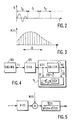
- a calling modem 100 transmits on a channel 105, to a modem called 110, respectively two test sequences L 1 and L 2 which are used to determine the characteristics of the channel and to select the mode modulation to use.
- the L 2 sequence is identical to the L 1 sequence except that it is emitted at 6 dB above the nominal power level.
- the sequence L 1 is used . It is made up of a periodic set of tones (cosines) spaced 150 Hz apart from one another at frequencies ranging from 150 Hz to 3750 Hz. Tones at 900 Hz, 1200 Hz, 1800 Hz and 2400 Hz are omitted because they constitute particular tones for communications between modems.
- the signals generated for each tone have a phase initial 180 ° for tones at 450 Hz, 600 Hz, 1500 Hz, 2250 Hz, 3000 Hz, 3150 Hz, 3450 Hz, 3600 Hz, 3750 Hz.
- the initial phase is zero for other tones.
- the tones are organized in 10 different bands of frequencies, numbered from 1 to 11, which can be selected by based on noise conditions on the channel.
- the channel is a telephone line.
- the transmission of the sequence L 1 is intended to determine the quality of the channel for different bands at different bit rates.
- the authorized bit rates are multiples of 2400 bits / s and range from 2400 bits / s to 28.8 bits / s.
- the bandwidths are defined according to Table I: band number bandwidth center frequency initial frequency final frequency 1 2400 1600 400 2800 2 2400 1800 600 3000 3 2743 1646 274 3017 4 2743 1829 457 3200 5 2800 1680 280 3080 6 2800 1867 467 3267 7 3000 1800 300 3300 8 3000 2000 500 3500 9 3200 1829 229 3429 10 3200 1920 320 3520 11 3429 1958 244 3673
- the invention proposes to select the band of most favorable frequencies for transmission and bit rate taking into account the characteristics of the channel at the time of the test and characteristics of the receiving means.
- FIG. 2 provides an example of the form of the sequence S (f i ) received periodically as a function of time, according to a series of periods T0, T1, ... For each period, the sequence is sampled and subjected to a Fourier transform which delivers a transfer function of the channel H (f i ).
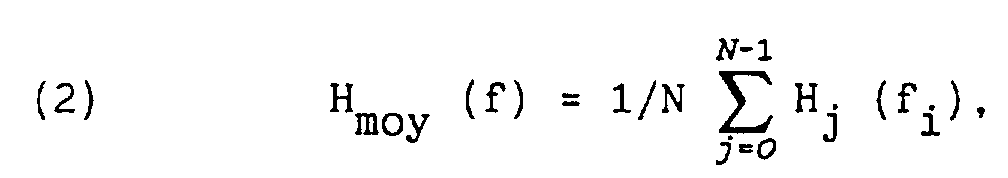
- a sequence of Fourier transforms is carried out over several periods of the signal. For example, the following measurements are obtained by performing 64 Fourier transforms:
- H 0 (150 Hz) [measured] H 0 (150 Hz) [channel] + N 0 (150 Hz) [noise].
- H avg (f i ) and ⁇ 2 / avg (f i ) make it possible to define the characteristics of the channel before the establishment of the communication.
- H moy (f i ) will be simplified in H (f i ) and the writing of ⁇ 2 / moy (f i ) will be simplified in ⁇ 2 (f i ).
- Figure 5 shows a theoretical model incorporating the channel, the superimposed noise and the station called.
- the noise ⁇ r 2 generated by the called station is estimated beforehand by preliminary measurements carried out with known channels.
- This noise ⁇ r 2 is an intrinsic characteristic of the called station, a characteristic which remains stable thereafter, during the test stages of the channel and during operation.
- test means can estimate the ratio predictable signal / noise at the output of the station called and select the frequency band and bit rate accordingly better suited for transmission.
- FIG. 6 shows a flow diagram of the operations implemented in the method.
- the calling station [block 100] transmits the sequence L 1 on the channel [block 105].
- the station called [block 110] receives a sequence S (f i ) at the channel output. This is sampled [block 120] then during each period constituting the sequence, a Fourier transform [block 130] is performed to deliver the measured transfer function of the channel.
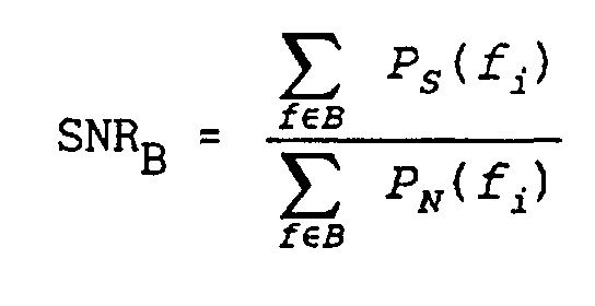
- the method successively selects [block 140] each authorized transmission band and then determines the characteristics of the channel in each of these transmission bands. It delivers the signal power H 2 (f i ) [block 150] and the noise power ⁇ 2 (f i ) [block 250] from the channel.
- This SNR B estimate is compared [block 190] to known theoretical SNR th (B) values, previously determined, relating to these same bands B for different bit rates D.
- B SNR th
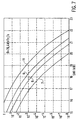
- Such values can be deduced for example from the curves represented in FIG. 7 Indeed, one can calculate the maximum performances which it is possible to reach in the case of a channel and a station called both perfect. These performances depend, among other things, on the bit rate D that one wants to transmit on the channel and on the frequency band used B.
- the probability of ERR errors has been represented as a function of the signal / noise for different frequency bands in the case of a bit rate of 26.4 kbit / s.
- the curves 6, 7, 8 and 11 correspond to the frequency bands 6, 7, 8 and 11 of FIG. 1. Similar curves exist for the other bands and for other bit rates.
- the system transmits (connection 220) to the station called the band (s) B suitable for transmission and the rate (s) D [block 195 ] which itself transmits the information to the calling station to establish communication.
- the noise, generated by the reception means themselves, is estimated during a preliminary step. For this, a channel having known performance is used and the signal to noise ratio obtained at the output of the reception means is measured. Using equations 7 and 8, we obtain an estimate of the value ⁇ r 2 which constitutes a characteristic of the reception means. It then remains constant in the operation of the system.
- Figure 4 shows a block diagram of the entire transmission system. It comprises, communicating via a channel 105, a calling station 100 and reception means 14 comprising a station called 110 and test means 16.
- the calling station transmits the sequence L 1 which becomes the sequence S (f i ) at l entrance to the station called.
- the sequence S (f i ) is introduced into test means 16 for measuring the quality of the channel.
- the test means comprise a sampler 15 followed by a device for digital processing of the DSP signal 17.
- the sampler 15 performs step 120 of FIG. 6 and the device 17 performs the other steps of FIG. 6.
- the device 17 transmits this information (connection 220) to the called station which in turn transmits it to the calling station to establish the communication.
- a calling station becomes a called station in the case of reverse communication. This is what happens during the V.34 test procedure chosen as an example.
- the latter is successively connected to several channels 105 having known characteristics for which there are known measurements of signal to noise ratio.
- the signal / noise ratio at the output of the station called (connection 20) is measured and by successive approximations, a value ⁇ r 2 of the noise is determined which is compatible with the various signal / noise ratios expected.
Description
- des moyens pour calculer, pour chaque bande, un rapport entre une puissance du signal de la séquence et une puissance de bruit incluant la puissance de bruit de canal et une variance, préalablement estimée, des bruits dus aux moyens de réception,
- des moyens pour comparer, pour chaque bande, le rapport avec un rapport maximal théorique propre à chaque bande,
- des moyens pour sélectionner les bandes et les débits pour lesquels les rapports sont inférieurs aux rapports maximaux théoriques respectifs et pour transmettre la sélection aux moyens d'émission.
- échantillonner la séquence reçue,
- effectuer, pour différentes bandes de fréquences, pour différents débits binaires, au moins une transformée de Fourier pour calculer, sur la pluralité de fréquences, la fonction de transfert du canal et pour en déduire une puissance de signal dans la bande et une puissance de bruit de canal dans la bande,
- calculer un rapport entre la puissance de signal et une puissance de bruit incluant la puissance de bruit de canal et une variance, préalablement estimée, des bruits dus aux moyens de réception,
- comparer, pour chaque bande, le rapport avec un rapport maximal théorique propre à chaque bande,
- sélectionner les bandes et les débits pour lesquels les rapports sont inférieurs aux rapports maximaux théoriques respectifs,
- transmettre la sélection aux moyens d'émission.
et avec i≠6, i≠8, i≠12, i≠16.
| numéro de bande | largeur de bande | fréquence centrale | fréquence initiale | fréquence finale |
| 1 | 2400 | 1600 | 400 | 2800 |
| 2 | 2400 | 1800 | 600 | 3000 |
| 3 | 2743 | 1646 | 274 | 3017 |
| 4 | 2743 | 1829 | 457 | 3200 |
| 5 | 2800 | 1680 | 280 | 3080 |
| 6 | 2800 | 1867 | 467 | 3267 |
| 7 | 3000 | 1800 | 300 | 3300 |
| 8 | 3000 | 2000 | 500 | 3500 |
| 9 | 3200 | 1829 | 229 | 3429 |
| 10 | 3200 | 1920 | 320 | 3520 |
| 11 | 3429 | 1959 | 244 | 3673 |

Claims (4)
- Procédé pour tester un canal de transmission par émission, sur le canal, par des moyens d'émission, d'une séquence de test comportant une pluralité de fréquences de test et pour sélectionner, à la réception, au moins une bande de fréquences apte à la transmission, le procédé comprenant les étapes suivantes effectuées par des moyens de réception:échantillonner la séquence reçue,effectuer, pour différentes bandes de fréquences, pour différents débits binaires, au moins une transformée de Fourier pour calculer, sur la pluralité de fréquences, la fonction de transfert du canal et pour en déduire une puissance de signal dans la bande et une puissance de bruit de canal dans la bande,calculer un rapport entre la puissance de signal et une puissance de bruit incluant la puissance de bruit de canal et une variance, préalablement estimée, des bruits dus aux moyens de réception,comparer, pour chaque bande, le rapport avec un rapport maximal théorique propre à chaque bande,sélectionner les bandes et les débits pour lesquels les rapports sont inférieurs aux rapports maximaux théoriques respectifs,transmettre la sélection aux moyens d'émission.
- Procédé selon la revendication 1 comprenant une étape préliminaire pour estimer la variance des bruits dus aux moyens de réception, étape effectuée en comparant le rapport signal/bruit en sortie des moyens de réception avec le rapport signal/bruit mesuré en sortie de canal pour au moins un canal de caractéristiques connues.
- Système de communication comprenant des moyens d'émission et des moyens de réception communiquant à travers un canal de transmission, les moyens d'émission émettant, sur le canal, une séquence de test comportant une pluralité de fréquences de test, les moyens de réception comportant des moyens de test comprenant des moyens pour calculer, pour différents débits binaires, sur la pluralité de fréquences, une puissance de bruit de canal dans des bandes de fréquences pour tester une qualité du canal en calculant une fonction de transfert du canal et pour sélectionner au moins une bande de fréquences pour la transmission caractérisé en ce que les moyens de test comprennent:des moyens pour calculer, pour chaque bande, un rapport entre une puissance du signal de la séquence et une puissance de bruit incluant la puissance de bruit de canal et une variance, préalablement estimée, des bruits dus aux moyens de réception,des moyens pour comparer, pour chaque bande, le rapport avec un rapport maximal théorique propre à chaque bande,des moyens pour sélectionner les bandes et les débits pour lesquels le rapport est inférieur aux rapports maximaux théoriques respectifs et pour transmettre la sélection aux moyens d'émission.
- Système selon la revendication 3 caractérisé en ce que les moyens de test comportent un dispositif calculateur pour réaliser les calculs, les comparaisons et les sélections de bandes et de débits.
Applications Claiming Priority (2)
| Application Number | Priority Date | Filing Date | Title |
|---|---|---|---|
| FR9502712 | 1995-03-08 | ||
| FR9502712A FR2731571A1 (fr) | 1995-03-08 | 1995-03-08 | Systeme de communication muni de moyens pour tester un canal de transmission et procede de test |
Publications (2)
| Publication Number | Publication Date |
|---|---|
| EP0731573A1 EP0731573A1 (fr) | 1996-09-11 |
| EP0731573B1 true EP0731573B1 (fr) | 2002-09-04 |
Family
ID=9476867
Family Applications (1)
| Application Number | Title | Priority Date | Filing Date |
|---|---|---|---|
| EP96200583A Expired - Lifetime EP0731573B1 (fr) | 1995-03-08 | 1996-03-05 | Procédé et dispositif pour tester un canal de transmission dans un système de communication |
Country Status (6)
| Country | Link |
|---|---|
| US (1) | US5802446A (fr) |
| EP (1) | EP0731573B1 (fr) |
| JP (1) | JP3945590B2 (fr) |
| DE (1) | DE69623363T2 (fr) |
| FR (1) | FR2731571A1 (fr) |
| TW (1) | TW346711B (fr) |
Families Citing this family (30)
| Publication number | Priority date | Publication date | Assignee | Title |
|---|---|---|---|---|
| FR2736781B1 (fr) * | 1995-07-13 | 1997-09-26 | Sgs Thomson Microelectronics | Circuit de transmission de donnees binaires sur le reseau electrique utilisant plusieurs canaux de transmission |
| US5870429A (en) * | 1996-06-17 | 1999-02-09 | Motorola, Inc. | Apparatus method, and software modem for utilizing envelope delay distortion characteristics to determine a symbol rate and a carrier frequency for data transfer |
| JPH1028088A (ja) * | 1996-07-11 | 1998-01-27 | Nec Corp | 携帯電話無線基地局の試験用送受信装置 |
| US5982752A (en) * | 1997-04-25 | 1999-11-09 | Mci Communications Corporation | Method and apparatus for detecting multiplexing standard mismatches in communication networks |
| US6647058B1 (en) | 1997-06-23 | 2003-11-11 | Paradyne Corporation | Performance customization system and process for optimizing XDSL performance |
| US6005890A (en) * | 1997-08-07 | 1999-12-21 | Pittway Corporation | Automatically adjusting communication system |
| US6021268A (en) * | 1997-08-21 | 2000-02-01 | Analytical Graphics, Inc. | Method and apparatus for modeling receiver bandwidth for telecommunications analysis |
| US6167031A (en) * | 1997-08-29 | 2000-12-26 | Telefonaktiebolaget Lm Ericsson (Publ) | Method for selecting a combination of modulation and channel coding schemes in a digital communication system |
| US5991337A (en) * | 1997-11-24 | 1999-11-23 | 3Com Corporation | Method and apparatus for improving the signal-to-noise ratio of low-magnitude input signals in modems |
| US6775840B1 (en) | 1997-12-19 | 2004-08-10 | Cisco Technology, Inc. | Method and apparatus for using a spectrum analyzer for locating ingress noise gaps |
| US6700875B1 (en) * | 1998-03-31 | 2004-03-02 | Motorola, Inc. | System, device, and method for selecting a channel in a multichannel communication network |
| KR100548235B1 (ko) * | 1998-12-15 | 2006-04-10 | 엘지전자 주식회사 | 반송파 주파수 결정 방법 |
| US6574797B1 (en) | 1999-01-08 | 2003-06-03 | Cisco Technology, Inc. | Method and apparatus for locating a cleaner bandwidth in a frequency channel for data transmission |
| US7003078B2 (en) * | 1999-01-29 | 2006-02-21 | Sbc Knowledge Ventures, Lp | Method and apparatus for telephone line testing |
| US6324167B1 (en) * | 1999-02-23 | 2001-11-27 | Ameritech Corporation | Method and system for conveying multiple calls on a single telephone line |
| US6480315B1 (en) * | 1999-08-06 | 2002-11-12 | Nortel Networks Limited | Method and apparatus for SNR measurement |
| US6418160B1 (en) | 2000-03-29 | 2002-07-09 | Sbc Technology Resources, Inc. | Method for testing a communication channel |
| US6473597B1 (en) | 2000-04-12 | 2002-10-29 | Thomas M. Johnson | Method and apparatus for modeling transmitter bandwidth for telecommunications analysis |
| JP2002245962A (ja) * | 2000-12-12 | 2002-08-30 | Jeol Ltd | エレクトロスプレー・イオン源 |
| US6541977B2 (en) * | 2001-02-13 | 2003-04-01 | Pulsar 2000, Inc. | Electronic water line tracer |
| WO2002075571A1 (fr) * | 2001-03-16 | 2002-09-26 | Otg Software, Inc. | Systeme et procede de partage de fichiers reseau |
| JP2003070056A (ja) * | 2001-08-28 | 2003-03-07 | Ntt Docomo Inc | 通信チャネル設定方法、通信制御装置及び無線通信システム |
| US7593511B2 (en) * | 2001-11-19 | 2009-09-22 | Alcatel Lucent | Method for training line drivers in a communication system |
| JP3591726B2 (ja) * | 2001-12-07 | 2004-11-24 | ソニー株式会社 | データ通信制御システム、送信機及び送信方法 |
| US7620154B2 (en) | 2002-12-23 | 2009-11-17 | Cambron G Keith | Equivalent working length determinative system for digital subscriber line circuits |
| GB2404822B (en) * | 2003-08-07 | 2007-07-11 | Ipwireless Inc | Method and arrangement for noise variance and sir estimation |
| US7768930B1 (en) * | 2004-09-17 | 2010-08-03 | Avaya Inc | Method and apparatus for determining problems on digital systems using audible feedback |
| KR101606598B1 (ko) * | 2009-09-30 | 2016-03-25 | 한국전자통신연구원 | 특이값 분해를 이용한 백색가우시안 잡음대역 결정 시스템 및 그 방법 |
| US8225252B2 (en) * | 2010-06-25 | 2012-07-17 | Intel Corporation | Systems, methods, apparatus and computer readable mediums for use in association with systems having interference |
| RU2705771C1 (ru) * | 2019-03-27 | 2019-11-11 | Акционерное общество "Калужский научно-исследовательский институт телемеханических устройств" | Способ моделирования независимых и группирующихся ошибок канала связи |
Family Cites Families (9)
| Publication number | Priority date | Publication date | Assignee | Title |
|---|---|---|---|---|
| US4633411A (en) * | 1982-12-27 | 1986-12-30 | Rockwell International Corporation | Link quality analyzer |
| US5048054A (en) * | 1989-05-12 | 1991-09-10 | Codex Corporation | Line probing modem |
| DE4014766A1 (de) * | 1990-04-19 | 1992-01-09 | Siemens Ag | Verfahren zum ermitteln von qualitaetsparametern einer uebertragungsstrecke fuer digitale datenstroeme mit zellenstruktur |
| US5214675A (en) * | 1991-07-02 | 1993-05-25 | Motorola, Inc. | System and method for calculating channel gain and noise variance of a communication channel |
| US5297186A (en) * | 1991-07-29 | 1994-03-22 | Codex Corporation | Device and method for on-line adaptive selection of baud rate and carrier frequency |
| EP0548939B1 (fr) * | 1991-12-26 | 2000-09-13 | Nec Corporation | Système de commande de puissance d'émission permettant de garder une qualité constante du signal dans un réseau de communication mobile |
| US5305468A (en) * | 1992-03-18 | 1994-04-19 | Motorola, Inc. | Power control method for use in a communication system |
| JP3135999B2 (ja) * | 1992-09-18 | 2001-02-19 | リーダー電子株式会社 | Cn比測定装置 |
| JP2993554B2 (ja) * | 1994-05-12 | 1999-12-20 | エヌ・ティ・ティ移動通信網株式会社 | 送信電力制御法および前記送信電力制御法を用いた通信装置 |
-
1995
- 1995-03-08 FR FR9502712A patent/FR2731571A1/fr not_active Withdrawn
-
1996
- 1996-03-05 EP EP96200583A patent/EP0731573B1/fr not_active Expired - Lifetime
- 1996-03-05 JP JP4727796A patent/JP3945590B2/ja not_active Expired - Fee Related
- 1996-03-05 DE DE69623363T patent/DE69623363T2/de not_active Expired - Fee Related
- 1996-03-07 US US08/612,156 patent/US5802446A/en not_active Expired - Fee Related
- 1996-03-22 TW TW085103494A patent/TW346711B/zh active
Also Published As
| Publication number | Publication date |
|---|---|
| JPH08265228A (ja) | 1996-10-11 |
| US5802446A (en) | 1998-09-01 |
| TW346711B (en) | 1998-12-01 |
| EP0731573A1 (fr) | 1996-09-11 |
| DE69623363T2 (de) | 2003-06-26 |
| DE69623363D1 (de) | 2002-10-10 |
| JP3945590B2 (ja) | 2007-07-18 |
| FR2731571A1 (fr) | 1996-09-13 |
Similar Documents
| Publication | Publication Date | Title |
|---|---|---|
| EP0731573B1 (fr) | Procédé et dispositif pour tester un canal de transmission dans un système de communication | |
| US5715277A (en) | Apparatus and method for determining a symbol rate and a carrier frequency for data transmission and reception | |
| EP0113487B1 (fr) | Procédé utilisé dans un dispositif d'annulation d'écho pour la mesure d'un retard d'écho et dispositif de mise en oeuvre de ce procédé | |
| FR2602933A1 (fr) | Ensemble d'abonne pour telephonie numerique sans fil; modem et dispositifs divers (synthetiseur de frequence...) pour cet ensemble | |
| FR2748169A1 (fr) | Circuit detecteur d'erreurs pour recepteur numerique utilisant un seuil variable fonde sur la qualite du signal | |
| FR2736229A1 (fr) | Procede d'echange adaptatif de bits et dispositif pour systeme a tons multiples discrets | |
| WO2008009620A1 (fr) | Systeme d'estimation de la qualite de reception d'une transmission numerique | |
| EP0549445B1 (fr) | Procédé de transmission de signaux de référence dans un système de transmission de données sur plusieurs porteuses | |
| EP1322970B1 (fr) | Procede et dispositif de mesure de l'attenuation d'une ligne | |
| EP1303071B1 (fr) | Procédé et dispositif de sélection automatique du débit dans des transmissions haute fréquence | |
| EP2351241B1 (fr) | Procede d'emission tenant compte de l'echo | |
| EP1311078B1 (fr) | Procédé de mesure du taux d'erreur d'un système de transmission optique et dispositif pour la mise en oeuvre de ce procédé | |
| EP0994609A1 (fr) | Méthode de construction d'un ensemble de constellations destiné à être utilisé pour transmettre des données entre un émetteur et un récepteur | |
| FR2844407A1 (fr) | Procede de selection de canal de transmission et recepteur de signaux a diversite d'antenne | |
| EP0212030B1 (fr) | Dispositif de détection de fin d'energie d'un signal de données | |
| EP0497250B1 (fr) | Procédé de détection de signal perturbateur pour démodulateur de données numériques et dispositif de mise en oeuvre d'un tel procédé | |
| FR2733867A1 (fr) | Procede et dispositif de mesure sans intrusion de la qualite de transmission d'une ligne telephonique | |
| FR2724513A1 (fr) | Systeme de transmission numerique synchronisable sur ses sequences d'initialisation | |
| EP0184953A1 (fr) | Procédé et dispositif de transmission d'information numérique par déplacement différentiel de fréquence | |
| EP2163059A1 (fr) | Procédé de réception d'un signal transmis multiplexe en fréquence | |
| WO2010130915A1 (fr) | Scrutation de bande de radiocommunications | |
| WO2012028808A1 (fr) | Procédé et système de transmission de données par ondes porteuses non-linéaires | |
| FR2903547A1 (fr) | Procede de parametrage d'une transmission de bits pour systeme a porteuses multiples avec voie de retour. | |
| FR2550673A1 (fr) | Systeme de transmission telephonique comprenant au moins un vocodeur a bande de base associe a un modem | |
| WO2000022751A1 (fr) | Procede de mise en service d'une liaison de donnees numeriques empruntant un milieu de transmission sujet aux perturbations |
Legal Events
| Date | Code | Title | Description |
|---|---|---|---|
| PUAI | Public reference made under article 153(3) epc to a published international application that has entered the european phase |
Free format text: ORIGINAL CODE: 0009012 |
|
| AK | Designated contracting states |
Kind code of ref document: A1 Designated state(s): BE DE FR GB |
|
| 17P | Request for examination filed |
Effective date: 19970311 |
|
| RAP1 | Party data changed (applicant data changed or rights of an application transferred) |
Owner name: KONINKLIJKE PHILIPS ELECTRONICS N.V. |
|
| 17Q | First examination report despatched |
Effective date: 20010220 |
|
| GRAG | Despatch of communication of intention to grant |
Free format text: ORIGINAL CODE: EPIDOS AGRA |
|
| GRAG | Despatch of communication of intention to grant |
Free format text: ORIGINAL CODE: EPIDOS AGRA |
|
| GRAH | Despatch of communication of intention to grant a patent |
Free format text: ORIGINAL CODE: EPIDOS IGRA |
|
| GRAH | Despatch of communication of intention to grant a patent |
Free format text: ORIGINAL CODE: EPIDOS IGRA |
|
| GRAA | (expected) grant |
Free format text: ORIGINAL CODE: 0009210 |
|
| AK | Designated contracting states |
Kind code of ref document: B1 Designated state(s): BE DE FR GB |
|
| REG | Reference to a national code |
Ref country code: GB Ref legal event code: FG4D Free format text: NOT ENGLISH |
|
| REF | Corresponds to: |
Ref document number: 69623363 Country of ref document: DE Date of ref document: 20021010 |
|
| GBT | Gb: translation of ep patent filed (gb section 77(6)(a)/1977) |
Effective date: 20021029 |
|
| REG | Reference to a national code |
Ref country code: FR Ref legal event code: D6 |
|
| REG | Reference to a national code |
Ref country code: GB Ref legal event code: 746 Effective date: 20021231 |
|
| PG25 | Lapsed in a contracting state [announced via postgrant information from national office to epo] |
Ref country code: BE Free format text: LAPSE BECAUSE OF NON-PAYMENT OF DUE FEES Effective date: 20030331 |
|
| PLBE | No opposition filed within time limit |
Free format text: ORIGINAL CODE: 0009261 |
|
| STAA | Information on the status of an ep patent application or granted ep patent |
Free format text: STATUS: NO OPPOSITION FILED WITHIN TIME LIMIT |
|
| 26N | No opposition filed |
Effective date: 20030605 |
|
| BERE | Be: lapsed |
Owner name: KONINKLIJKE *PHILIPS ELECTRONICS N.V. Effective date: 20030331 |
|
| PGFP | Annual fee paid to national office [announced via postgrant information from national office to epo] |
Ref country code: DE Payment date: 20060522 Year of fee payment: 11 |
|
| PGFP | Annual fee paid to national office [announced via postgrant information from national office to epo] |
Ref country code: GB Payment date: 20070327 Year of fee payment: 12 |
|
| PG25 | Lapsed in a contracting state [announced via postgrant information from national office to epo] |
Ref country code: DE Free format text: LAPSE BECAUSE OF NON-PAYMENT OF DUE FEES Effective date: 20071002 |
|
| PGFP | Annual fee paid to national office [announced via postgrant information from national office to epo] |
Ref country code: FR Payment date: 20070329 Year of fee payment: 12 |
|
| GBPC | Gb: european patent ceased through non-payment of renewal fee |
Effective date: 20080305 |
|
| REG | Reference to a national code |
Ref country code: FR Ref legal event code: ST Effective date: 20081125 |
|
| PG25 | Lapsed in a contracting state [announced via postgrant information from national office to epo] |
Ref country code: FR Free format text: LAPSE BECAUSE OF NON-PAYMENT OF DUE FEES Effective date: 20080331 |
|
| PG25 | Lapsed in a contracting state [announced via postgrant information from national office to epo] |
Ref country code: GB Free format text: LAPSE BECAUSE OF NON-PAYMENT OF DUE FEES Effective date: 20080305 |