EP0732474A1 - Hinge device - Google Patents
Hinge device Download PDFInfo
- Publication number
- EP0732474A1 EP0732474A1 EP96102973A EP96102973A EP0732474A1 EP 0732474 A1 EP0732474 A1 EP 0732474A1 EP 96102973 A EP96102973 A EP 96102973A EP 96102973 A EP96102973 A EP 96102973A EP 0732474 A1 EP0732474 A1 EP 0732474A1
- Authority
- EP
- European Patent Office
- Prior art keywords
- cam
- hinge device
- spring
- transmitter
- opening
- Prior art date
- Legal status (The legal status is an assumption and is not a legal conclusion. Google has not performed a legal analysis and makes no representation as to the accuracy of the status listed.)
- Granted
Links
Images


Classifications
-
- H—ELECTRICITY
- H04—ELECTRIC COMMUNICATION TECHNIQUE
- H04M—TELEPHONIC COMMUNICATION
- H04M1/00—Substation equipment, e.g. for use by subscribers
- H04M1/02—Constructional features of telephone sets
- H04M1/0202—Portable telephone sets, e.g. cordless phones, mobile phones or bar type handsets
- H04M1/0206—Portable telephones comprising a plurality of mechanically joined movable body parts, e.g. hinged housings
- H04M1/0208—Portable telephones comprising a plurality of mechanically joined movable body parts, e.g. hinged housings characterized by the relative motions of the body parts
- H04M1/0214—Foldable telephones, i.e. with body parts pivoting to an open position around an axis parallel to the plane they define in closed position
- H04M1/0216—Foldable in one direction, i.e. using a one degree of freedom hinge
-
- E—FIXED CONSTRUCTIONS
- E05—LOCKS; KEYS; WINDOW OR DOOR FITTINGS; SAFES
- E05D—HINGES OR SUSPENSION DEVICES FOR DOORS, WINDOWS OR WINGS
- E05D7/00—Hinges or pivots of special construction
- E05D7/04—Hinges adjustable relative to the wing or the frame
-
- E—FIXED CONSTRUCTIONS
- E05—LOCKS; KEYS; WINDOW OR DOOR FITTINGS; SAFES
- E05D—HINGES OR SUSPENSION DEVICES FOR DOORS, WINDOWS OR WINGS
- E05D11/00—Additional features or accessories of hinges
- E05D11/10—Devices for preventing movement between relatively-movable hinge parts
- E05D11/1028—Devices for preventing movement between relatively-movable hinge parts for maintaining the hinge in two or more positions, e.g. intermediate or fully open
- E05D11/105—Devices for preventing movement between relatively-movable hinge parts for maintaining the hinge in two or more positions, e.g. intermediate or fully open the maintaining means acting perpendicularly to the pivot axis
-
- E—FIXED CONSTRUCTIONS
- E05—LOCKS; KEYS; WINDOW OR DOOR FITTINGS; SAFES
- E05F—DEVICES FOR MOVING WINGS INTO OPEN OR CLOSED POSITION; CHECKS FOR WINGS; WING FITTINGS NOT OTHERWISE PROVIDED FOR, CONCERNED WITH THE FUNCTIONING OF THE WING
- E05F1/00—Closers or openers for wings, not otherwise provided for in this subclass
- E05F1/08—Closers or openers for wings, not otherwise provided for in this subclass spring-actuated, e.g. for horizontally sliding wings
- E05F1/10—Closers or openers for wings, not otherwise provided for in this subclass spring-actuated, e.g. for horizontally sliding wings for swinging wings, e.g. counterbalance
- E05F1/12—Mechanisms in the shape of hinges or pivots, operated by springs
-
- E—FIXED CONSTRUCTIONS
- E05—LOCKS; KEYS; WINDOW OR DOOR FITTINGS; SAFES
- E05Y—INDEXING SCHEME RELATING TO HINGES OR OTHER SUSPENSION DEVICES FOR DOORS, WINDOWS OR WINGS AND DEVICES FOR MOVING WINGS INTO OPEN OR CLOSED POSITION, CHECKS FOR WINGS AND WING FITTINGS NOT OTHERWISE PROVIDED FOR, CONCERNED WITH THE FUNCTIONING OF THE WING
- E05Y2900/00—Application of doors, windows, wings or fittings thereof
- E05Y2900/60—Application of doors, windows, wings or fittings thereof for other use
- E05Y2900/606—Application of doors, windows, wings or fittings thereof for other use for electronic devices
Definitions
- the present invention relates to a hinge device that is ideal for use in electronic devices such as cellular phones, laptop computers, electronic datebooks and the like, which enables such devices to be closed shut, when not in use, or opened to a specific angle by folding open one portion of the device such as, for example, the transmitter in the case of a cellular telephone, or the display in the case of a laptop computer.
- a hinge device is employed as the connection between the member which is moved to open or shut the device and the member which remains fixed or stationary (hereinafter, the member portion which is moved to open or close the device, i.e., the telephone transmitter or the laptop display, will be referred to as the "opening-closing member", while the portion of the device which remains stationary or is held in a fixed position will be referred to as the "stationary member”).
- the hinge device is disposed along the lateral edge of the stationary member to which the opening-closing member is connected. The two members of the device are joined along the entire region of connection between their two edges.
- the present invention was conceived in consideration of the aforementioned circumstances, and has as an objective the provision of a hinge device whereby the opening and closing operations can be carried out smoothly and with surety, this hinge device contributing to making the electronic device more compact. Further, it is also an objective of the present invention to provide a hinge device which improves the esthetic appearance of the electronic device in which it is employed by providing a space for housing wiring or the like.
- the present invention employs the following design in order to resolve the problems described above.
- the opening-closing member of an electronic device is connected to one lateral edge of the stationary member in a manner to permit free opening and closing thereof.
- This hinge device has two main bodies which are disposed respectively at either end of the aforementioned lateral edge of the stationary member, along the longitudinal direction thereof. These hinge main bodies are each provided with a cam shaft and spring.
- This cam shaft is affixed to one of the stationary member and the opening-closing member by positioning the axis of the cam shaft parallel to the lateral edge of the stationary member, and has a cam at its axis periphery.
- the spring is affixed to one of the opening-closing member and the stationary member to which the cam shaft is not affixed, and is characterized in that it elastically grips the cam of the cam shaft.
- the cam is provided with a pair of holding surfaces which are disposed symmetrically about the aforementioned axis, at which the cam is held in a predetermined position by the spring.
- These holding surfaces are flat surfaces or inwardly depressed surfaces to form concave surfaces.
- the holding surfaces may be lenticulated, in a triangular wave shape or the like, or their circumscribed enveloping surfaces may be flat or indented inward, without impinging on their function, such that the cam can be held in a predetermined position.
- the cam is characterized in that the edges of the pair of holding surfaces are joined in a state such that they project outward to form a convexity, with a pair of curved surfaces being disposed symmetrically about the aforementioned axis.
- these curved surfaces are provided with reset force receiving surfaces.
- this reset force receiving surface receives a rotational force storing as the elastic restorativity in the spring to rotate it in a direction opposite to the rotation of the cam.
- this reset force receiving surface is an arced surface having a center line which is eccentric from the axis of the cam.
- the two cams which are disposed at either end of the aforementioned lateral edge differ from each other with respect to their shape in cross-section.
- one of the two cams is the principal holding cam which is held in a predetermined position by the spring, while the other cam is the principal reset cam upon which the elastic restorative force of the spring acts.
- a through hole which passes through the axis is formed in the cam shaft.
- Figure 1 is a planar view of an example of a cellular telephone employing a first embodiment of the hinge device of the present invention.
- Figure 2 is a front view of the cellular telephone, with the letters A, B, C and C' indicating different positions of the opening-closing member thereof during the opening and closing operations.
- Figure 3 is a side view showing the main body of the hinge device according to the first embodiment of the present invention, this figure showing the hinge device main body in cross-section along the line Y-Y shown in Figure 4.
- Figure 4 is a planar view of the hinge device main body, shown in cross-section along the line X-X shown in Figure 3.
- Figure 5 is an explanatory view showing the external shape of the cam in the hinge device main body, shown in cross-section along the line Z-Z shown in Figure 4. This figure corresponds to the position of the opening-closing member indicated by A in Figure 2.
- Figure 6 is an explanatory view showing the positional relationship between the cam and the spring for the cam shown in Figure 5. This figure corresponds to position B in Figure 2.
- Figure 7 is an explanatory view showing the positional relationship between the cam and the spring in the same cam. This figure corresponds to position C in Figure 2.
- Figure 8 is a view in lateral cross-section showing the external shape of the cam in the second embodiment of the hinge device of the present invention.
- Figure 9 is a front view showing an example of a cellular telephone employing the second embodiment of the present invention.
- Figure 10 is a view in lateral cross-section showing the external shape of the cam in the third embodiment of the hinge device of the present invention.
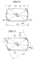
- Figure 11 is an explanatory view showing the positional relationship between the cam and the spring in the cam of the third embodiment of the present invention.
- Figure 12 is another explanatory view showing the positional relationship between the cam and the spring in the cam of the third embodiment of the present invention.
- Figure 13 is a view in lateral cross-section showing the external shape of the cam in the fourth embodiment of the hinge device of the present invention.
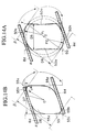
- Figures 14A and 14B are views in lateral cross-section showing the external shape of the cam in the fifth embodiment of the hinge device of the present invention, and are explanatory views showing the positional relationship between the cam and the spring.
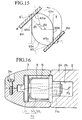
- Figure 15 is a view in lateral cross-section showing the external shape of the cam in the sixth embodiment of the hinge device of the present invention, in addition to being an explanatory view showing the positional relationship between the cam and the spring.
- Figure 16 is a front view showing the hinge device main body in the seventh embodiment of the hinge device of the present invention.
- Figure 17 is a view showing an example of a cellular telephone employing the seventh embodiment of the present invention.
- Figure 18 is a front view showing the hinge device main body in the eighth embodiment of the hinge device of the present invention.
- Figure 19A is a planar view
- Figure 19B is a front view
- Figure 19C is a lateral view viewed from the direction indicated by an arrow G in Figure 19A showing an alternative example of the spring in the hinge device of the present invention.
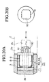
- Figure 20A is a front view and Figure 20B is a lateral view viewed from the direction indicated by an arrow H in Figure 20A showing an alternative example of the cam shaft in the hinge device of the present invention.
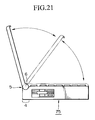
- Figure 21 is a front view showing an example of a laptop computer which employs the hinge device of the present invention.
- FIGS 1 and 2 show examples of a cellular telephone employing a first embodiment of the hinge device of the present invention.
- This cellular telephone 1 is principally composed of an operational member 2 (stationary member) and a transmitter 3 (opening-closing member).
- Transmitter 3 is connected to a lateral edge 4 of operational member 2 in a manner so as to open and close freely. This connection is achieved by means of hinge device 5.
- Hinge device 5 comprises two hinge device main bodies 6,6. These hinge device main bodies 6,6 are disposed to either end of lateral edge 4 along the longitudinal direction thereof.
- hinge device main body 6 Next, a detailed explanation will be made of the structure of hinge device main body 6 with reference being given to Figures 3 and 4.
- hinge device main body 6 is principally composed of cam shaft 7 and spring 8.
- Cam shaft 7 is formed of a metallic shaft 9 and a synthetic resin cam 10, for example.
- Shaft 9 is fixed to attached wall 2a of operational member 2, by positioning its axis parallel to lateral edge 4.
- Cam 10 is fixed around the axis of shaft 9.
- Shaft 9 has three axis regions, 9a, 9b, and 9c, which differ in diameter and are disposed in order of size. Pairs of flat portions 9d,9d and 9e,9e are formed symmetrically to axis regions 9b and 9c respectively, parallel to the axis.
- Axis region 9b is inserted into hole 2b of attached wall 2a, and flat portions 9d,9d catch on and are stopped by the inside wall of hole 2b to prevent the rotation of the axis periphery. Further, axis 9a is inserted into a hole 11a formed in lid 11 (explained below) such that play is permitted therebetween.
- cam 10 has a hole 10a which is formed to conform with the shape of axis regions 9a and 9b.
- cam 10 is comprised of a pair of holding surfaces 10b,10b, which are parallel to and symmetrically disposed about the cam axis, and a pair of arced surfaces 10c,10c (curved surfaces), which are disposed symmetrically about the axis and are joined to the edges of holding surfaces 10b,10b, forming a convexly curving surface therebetween.
- shaft 9 is fixed in position by positioning axis regions 9a,9b inside hole 10a.
- ring shaped member 12 is fixed to transmitter 3.
- Lid 11 is fixed to ring shaped member 12 through an engagement between a plurality of concavities 11b formed in lid 11 and a plurality of projections 12a formed to the inner peripheral surface of ring shaped member 12.
- Hole 11a and projections 11d are formed to the inner surface 11c of lid 11.
- Axis region 9a of the cam shaft engages inside hole 11a as described above.
- Spring 8 has a roughly cross-shaped flat plate 8a, with upright walls 8b,8b provided extending from the ends thereof. Holes 8c are formed in flat plate 8a of spring 8 in positions so as to match projections 11d of lid 11. Projections 11d and holes 8c engage to fix spring 8 to lid 11. Because spring 8 is fixed to lid 11, it is indirectly fixed to transmitter 3 via lid 11 and ring shaped member 12. Further, upright walls 8b,8b contact cam 10 via contact portions 8d,8d, elastically gripping cam 10.
- the shaft 9 of cam shaft 7 is inserted into hole 2b via a space located in the center of lateral edge 4 of operational member 2.
- the forward insertion of shaft 9 is stopped by the wall portions 9f of axis region 9c.
- flat portions 9d,9d of axis region 9b are stopped by the inner wall of the hole 2b preventing rotation of the rotation axis thereof.
- the cam portion 10 is inserted into shaft 9 from the outside of edge 4 of operational member 2 so that axis regions 9a,9b of shaft 9 are inserted into hole 10a.
- Spring 8 is fixed to lid 11 in advance by engaging projections 11d with holes 8c.
- Lid 11 is fixed to ring shaped member 12, to which transmitter 3 was fixed in advance, by engaging projections 12a with concavities 11b.
- Figures 5, 6, and 7 respectively depict the positional relationship between spring 8 and cam 10 of cam shaft 7 at the time when transmitter 3 is at each of the positions indicated by the letters A, B, and C in Figure 2. A separate explanation will be made for each stage of the opening and closing process of transmitter 3.
- contact portions 8d,8d move from a state of linear contact with arced surfaces 10c,10c to a state of planar contact with holding surfaces 10b,10b shown in Figure 7.
- This transition from the state shown in Figure 6 to that shown in Figure 7 is carried out in a single movement by means of only a slight amount of force.
- transition of the transmitter to position C occurs suddenly by application of only a slight rotational force when the transmitter is at position B.
- the operational mechanism to move transmitter 3 from position B to position A (closed) differs from the mechanism for opening the transmitter from position A to position B only with respect to the direction of rotation. Namely, spring 8 rotates in a clockwise direction as contact portions 8d,8d remain in contact with arced surfaces 10c,10c, gripping cam 10 therebetween.
- the curving arc shape of arced surface 10c also enables rotation to be smoothly performed at this point.
- a constant rotational force is applied to move transmitter 3 from position A to position B, after which the application of a slight amount of rotational force causes the transmitter to transit suddenly from position B to position C, that is to say, the open state. Further, since the open state wherein transmitter 3 is at position C shown in Figure 2 is stable, a large amount of rotational force is required to close transmitter 3.
- a large force brings transmitter 3 a sudden transition from position C to position B, and then a constant force is applied to smoothly carry out the closing operation from position B to position A.
- hinge device 5 when hinge device 5 is employed, the opening and closing operation is carried out easily and smoothly to transmitter 3, while, in addition, transmitter 3 can be held open with surety and stability at a specific angle (open state).
- Hinge device 5 is comprised of two hinge main bodies 6,6. These hinge main bodies 6,6 are disposed to the respective ends of lateral edge 4 of operational member 2, to which transmitter 3 is connected, along the longitudinal direction thereof. A freely opening and closing connection between transmitter 3 and operational member 2 is provided at these ends solely. Accordingly, space 13 which is positioned at the center of lateral edge 4 can be employed for purposes other than connection, such as, for example, a housing space for wiring or the like, thus contributing to making the device containing the present hinge device more compact.
- the angle to which transmitter 3 is opened can easily be designed to be an optional angle, including a large angle such as 150° as indicated by C' in Figure 2.
- cam 20 the external shape of which is shown in Figure 8
- cam 10 used in embodiment 1.
- the structure of this embodiment is the same. Accordingly, only cam 20 will be explained, with an explanation of the other parts omitted for brevity.
- the structure of cam 20 differs from cam 10 only in that the inclination of holding surfaces 20a differs.
- Cam 20 is provided with an hole (not shown) identical to that of hole 10a of cam 10, and with arced surfaces 20b (curved surface) identical to arced surfaces 10c of cam 10. Further, assembly of the device in this embodiment may be carried out in the same way as in Embodiment 1.
- the opening and closing operation of transmitter 3 in this embodiment differs in particular from that in embodiment 1 in that the holding angle (corresponding to position E) is 90° as shown in Figure 9 wherein A, D, and E indicate transitional positions of transmitter 3.
- the holding angle can be set to a desired value (90° in this embodiment). This contributes to making the device more compact, while providing the same surety and smoothness to the opening and closing operations as that provided in Embodiment 1.
- cam 30 the external shape of which is shown in Figure 10
- cam 30 the external shape of which is shown in Figure 10
- the structure is the same. Accordingly, an explanation will be made of cam 30 only, with an explanation of the other parts omitted for brevity.
- the structure of cam 30 differs from that of cam 20 only in that the center line of reset force receiving surfaces 30b (curved surface) is different.
- a hole (not shown) identical to the hole formed in cam 20, and holding surfaces 30a identical to holding surfaces 20a of cam 20 are formed in cam 30.
- Reset force receiving surfaces 30b,30b are arced surfaces having parallel straight lines P1,P2 as respective center lines, parallel straight lines P1,P2 being in an imaginary plane L1 and eccentric on either side of axis line O by equivalent distances. Further, assembly of the device in this embodiment is carried out in the same manner as in Embodiment 1.
- Reset force receiving surfaces 30b,30b are arced surfaces having straight lines P1,P2 as respective center lines.
- reset force receiving surfaces 30b,30b are positioned more external position with respect to the counter-clockwise direction than imaginary arced surfaces L2 centered about axis O. Accordingly, when an operation is carried out to open transmitter 3 from the closed state, the distance between contact portions 8d,8d of spring 8 widens from length D3 in Figure 10 to length D4 in figure 11.
- contact portions 8d,8d of spring 8 move from a state of planar contact with holding surfaces 30a,30a to a state of linear contact with reset force receiving surfaces 30b,30b.
- the device passes through the state shown in Figure 12. Since reset force receiving surfaces 30b are positioned further to the outside than imaginary arced surfaces L3 centered about axis O, the space between contact portions 8d,8d widens accompanying the operation to open transmitter 3 beyond the state shown in Figure 12, namely, accompanying the rotation of spring 8 in the counter-clockwise direction. Thus, a reset force in the clockwise direction is stored in spring 8.
- the reset force returns spring 8 to the state shown in Figure 12 once the opening operation ceases, and the transmitter 3 again returns to the open state due to the inertia to return to the state shown in Figure 12.
- transmitter 3 is maintained in either a closed state (A in Figure 9) or an open state (E in Figure 9), and does not enter an intermediate, or half-open, state wherein the transmitter is held open at some intermediate position which is at other than the desired angle.
- this embodiment is similar to that of Embodiment 2 in that the design contributes to making the device containing the present hinge device more compact and in that the device can be opened and closed smoothly and with surety.
- cam 40 is comprised of a hole (not shown in the figures) identical to that of hole 10a of cam 10, holding surfaces 40a identical to holding surfaces 10b of cam 10, and reset force receiving surfaces 40b (curved surface) identical to the reset force receiving surfaces 30b of cam 30.
- this embodiment has a structure which incorporates the characteristic aspects of the first and third embodiments. Accordingly, as explained in Embodiment 1, this contributes to making the device more compact, while permitting the opening and closing operation to be carried out smoothly and with surety. Further, the holding angle of transmitter 3 can be set to a desired value by optionally setting the angle of the holding surface 40a. Moreover, as explained in Embodiment 3, transmitter 3 can be held in either a predetermined open state or a predetermined closed state, without entering an intermediate, or half-open, state wherein the transmitter is held open at some intermediate position which is at other than the desired angle.
- This embodiment differs from the first embodiment only in that a holding cam50 and a reset cam 55, the external shapes of the portions held by contact portion 8d of spring 8 being shown in Figures 14A and 14B respectively, are employed in place of cam 10 in this embodiment.
- the remaining structures are identical. An explanation will therefore by made of reset cam 55 and holding cam 50 only, with an explanation of the other parts omitted here for brevity.
- Holding cam 50 and reset cam 55 are disposed to the respective ends of lateral edge 4, and differ in respect to the shape in cross-section of the portions thereof held by contact portion 8d of spring 8.
- Holding cam 50 is provided with concave surfaces 50a and reset force receiving surfaces 50b.
- Concave surface 50a is depressed inward and forms a holding surface at which holding cam 50 is held in a set position by spring 8.
- Reset force receiving surface 50b receives a rotational force from the elastic reset force of the spring 8 in a direction opposite the rotation of holding cam 50 when it rotates to the left (as shown in the figures) relative to spring 8.
- reset force receiving surface 50b is an arced surface having center lines P1,P2 which are eccentric from axis O of holding cam 50.
- Cam 50 principally functions to hold spring 8 in a predetermined position.
- Reset cam 55 is provided with reset force receiving surfaces 55b.
- Reset force receiving surface 55b receives a rotational force from the elastic reset force of spring 8 in a direction opposite the rotation of reset cam 55 when it is rotating to the left (in the figures) relative to spring 8.
- reset cam 55 has the shape of a parallelopiped, a large difference in the elastic forces which arise, depending on the position of the spring, can be achieved.
- the design of the device permits a large length ratio between length D8 and length D7 to be achieved, and enables the force needed for spring 8 to exceed corner 55c to be set to a large value.
- corner portions 55c,55d are rounded to guarantee smooth operation.
- reset cam 55 functions primarily to receive the elastic reset force arising from spring 8.
- ⁇ and ⁇ respectively correspond to the closed and opened positions of transmitter 3 with respect to operational member 2.
- ⁇ indicates an intermediate position along the path extending from ⁇ to ⁇ .
- Contact portions 8d,8d are in contact with the respective reset force receiving surfaces 50b and 55b of holding cam 50 and reset cam 55 in the closed state indicated by ⁇ in Figures 14A and 14B.
- transmitter 3 When transmitter 3 is opened from a closed state to the state indicated by ⁇ in Figures 14A and 14B, spring 8 rotates to the right (in the figures) as it is gripped with contact remaining between contact portions 8d,8d and the respective reset force receiving surfaces 50b and 55b of holding cam 50 and reset cam 55. When a rotational force is removed before transmitter 3 arrives at ⁇ , transmitter 3 returns to a closed state by the elastic reset force of spring 8.
- contact portions 8d,8d move from a state of contact with the respective reset force receiving surfaces 50b and 55b of holding cam 50 and reset cam 55, to a state of contact with the concave surface 50a (holding surface) of holding cam 50 and a state of contact with the approximately flat portion of reset cam 55 which is not the holding surface.
- This transition is carried out suddenly by means of only a slight amount of rotational force.
- transition to the state indicated by ⁇ in Figures 14A and 14B is carried out in a single movement.
- transmitter 3 When transmitter 3 is moved from the state indicated by ⁇ in Figures 14A and 14B to the closed state indicated by ⁇ , transmitter 3 will automatically return to a closed state by the elastic reset force of spring 8. That is to say, transmitter 3 will return to a closed state even in the absence of a force of rotation to return it to this state.
- a smooth opening operation is carried out from position ⁇ to ⁇ in resistance to the elastic reset force of the spring 8, with transition from ⁇ to the open state of ⁇ being accomplished suddenly through the application of only a slight amount of rotational force.
- transmitter 3 returns to a closed state by the elastic reset force of the spring 8.
- Transmitter 3 is stable in the open state, with a relatively large force being required to close it.
- the transmitter 3 moves suddenly from the positional state indicated by ⁇ to that indicated by ⁇ , with the transition from ⁇ to the closed state ⁇ occurring automatically by the elastic reset force of the spring 8.
- the opening and closing operations are carried out smoothly and easily, and transmitter 3 can be held open at a predetermined angle stably and with surety, without remaining a half-open state at an intermediate position between ⁇ and ⁇ .
- holding cam 50 and reset cam 55 which are disposed at either end of lateral edge 4, differ from each other with respect to the shape in cross-section of the portion gripped by spring 8. For this reason, greater flexibility can be imparted to the characteristics of the movement of the opening and closing operations. This would include, for example, allowing a wider range of options with respect to the setting of the holding angle, the rotational force required in the opening and closing operation, etc.
- the design of this embodiment provides a reliable holding function by means of concave surface 50a of holding cam 50, while preventing transmitter 3 from entering a half-open state through the employment of the reset force receiving surface 55b of reset cam 55.
- Embodiment 5 differs from Embodiment 5 only in that a reset cam 65 is employed in place of reset cam 55. All other structures are the same. An explanation will therefore be made here of reset cam 65 only, with an explanation of the other structures omitted for brevity.
- Reset cam 65 is provided with holding surfaces 65a,65b, which comprise flat surfaces, the edges of holding surfaces 65a and 65b connected by means of reset force receiving surface 65c.
- reset force receiving surface 65c Because of its location at a more internal position than the arced surface having axis O at its center, reset force receiving surface 65c has a rotation accelerating function which provides an accelerating force to the relative rotation of spring 8 by means of the spring's elastic reset force when spring 8 is rotated to the right (in the figures) relative to reset force receiving surface 65c. Further, if the relative rotation of spring 8 is in the opposite direction, then reset force receiving surface 65c receives a reset force, preventing transmitter 3 from remaining a half-open state.
- the opening operation from ⁇ 1 to ⁇ 2 is carried out suddenly through the application of a slight amount of force, in this case, the addition of acceleration effect makes the opening operation easier.
- reset force receiving surface 65c displays a function to prevent the transmitter from remaining in a half-open state.
- Opening and closing characteristics different from those in Embodiment 5 are realized in this embodiment. Namely, by employing two cams at either end of lateral edge 4 which differ from each other with respect to their shape in cross-section, greater flexibility can be imparted to the opening and closing characteristics, while increasing freedom of design.
- a seventh embodiment of the present invention shown in Figure 18 will now be explained.
- This embodiment differs from Embodiment 6 in that holding cam 50 and reset cam 55 are supported by a shaft 71 which is made of a synthetic resin, for example, and comprises a through hole 71a.
- One cam shaft 70 is formed by holding cam 50 and shaft 71, and the other cam shaft 70 is formed by reset cam 55 and shaft 71.
- a duplex of springs 8 is provided to supply a stronger elastic force.
- cam shaft 70 is engagingly into hole 2b of attached wall 2a to attach it to operational member 2.
- Springs 8,8 are attached to transmitter 3.
- Transmitter 3 is divided into two portions, which are held together by means of a screw 3a.
- through hole 71a can be employed for a purpose other than connection, such as, for example, a housing space for wiring.
- a purpose other than connection such as, for example, a housing space for wiring.
- this facilitates a more compact design for the device.
- through hole 71a is employed as a space for housing wiring 73, which is provided extending between operational member 2 and transmitter 3, for a transmission microphone 72 in transmitter 3, wire 73 is not exposed.
- this feature contributes to improving the aesthetic appearance of the device containing the present hinge device.
- Embodiment 7 differs from Embodiment 7 in that a integral transmitter 3 is employed in place of the structure of Embodiment 7 wherein a transmitter 3 that is positioned in the periphery of holding cam 50 and reset cam 55 is divided into two parts held in place by a screw 3a.
- lid 3b is designed to engage with transmitter 3.
- This embodiment offers the same effects as those offered by Embodiment 7.
- the elongated length of bead 8e is optional, and, for example, may be elongated from opposing edges of flat plate 8a, or may span only the middle region of flat plate 8a as shown in Figures 19A, 19B and 19C.
- the number of beads 8e provided is also optional, and may be two, as shown in Figures 19A, 19B and 19C, one, or three or more.
- the direction of projection of bead 8e may be oriented opposite upright walls 8b, as in Figures 19A, 19B and 19C, or may be oriented in the same direction as upright walls 8b.
- this bead 8e By means of the provision of this bead 8e, it is possible to improve the durability of the bending operation which accompanies opening and closing of the device, even in the case where upright walls 8b,8b undergo numerous repetitions of the bending operation in the direction indicated by F in the Figure 19B. Accordingly, the provision of this bead 8e is preferable. The improvement in durability arises because the provision of bead 8e provides the following characteristics.
- elongated ribs 61 are preferably formed which are elongated along the axis of cams 50,55 and project radially outward, at an engagement portion 60 of cams 50,55 which is attached to attached wall 2a of operational member 2, as shown in Figures 20A and 20B.
- the location, number, and shape of the elongated ribs 61 are optional.
- elongated ribs 61 are formed slightly larger than the internal diameter of hole 2b of attached wall 2a; thus, when engagement portion 60 of cams 50,55 come into engagement with hole 2b of operational member 2, elongated ribs 61 will be somewhat compressed. This produces an effect of fastening the engagement between cams 50,55 and operational member 2.
- cam shaft As described above, by incorporating elongated ribs, attachment of cam shaft to operational member 2 is performed rigidly, and thus, it becomes capable to bear against relatively large loads, and durability is improved.
- Embodiments 1 through 7 are applicable to Embodiments 1 through 7, but they are not shown in the figures.
- elongated ribs will be applied to axis region 9b of shaft 9 of cam shaft7.
- the hinge device of the present invention is in no way limited to this application alone, but may also be employed in a laptop computer 75 such as shown in Figure 21.
- application of the hinge device in other devices such electronic datebooks, toilet seats and the like, is of course possible.
- cam shafts 7 and 70 may instead be provided to the opening-closing member and the spring provided to the stationary member.
- connection between a stationary member and a opening-closing member is carried out by means of two hinge main bodies which are disposed to either end of the lateral edge of stationary member along the longitudinal direction thereof, in order to attach the opening-closing member being attached to the stationary member.
- the center region of this lateral edge can be employed for a purpose other than connection, such as, for example, a housing space for wiring.
- the cam shaft and spring rotate relative to each other with the spring elastically gripping the cam.
- the opening and closing operation of the opening-closing member can be carried out smoothly.
- the cam shaft and spring rotate relative to each other, and the opening-closing member is held at a specific angle stably with the spring gripping the holding surface. Accordingly, the opening and closing operation of the opening-closing member can be carried out with surety.
- the holding surface is a flat surface or a concave surface which is depressed inward, the holding of the cam by the spring is realized by means of a simple construction, and the holding of the cam at a specific angle can be carried out with greater surety.
- the opening and closing operation of the opening-closing member can be carried out smoothly.
- the curved surface is provided with a reset force receiving surface which receives a rotational force in a direction opposite to the direction of the rotation of the cam when the cam rotates relative to the spring due to the elastic reset force of the spring.
- this reset force receiving surface receives a reset force to return it to its original state due to the elastic reset force of the spring.
- the device does not remain in an intermediate, or half-open, state. Accordingly, the opening and closing operation can be carried out with greater surety, while imparting to the device a high level of operability.
- the reset force receiving surface is an arced surface having a center line which is eccentric from the axis of the cam, it is possible to guarantee smooth and easy opening and closing operations that can be realized through a simple construction.
- the two cams disposed to either end of the lateral edge are provided with shapes which differ from each other in cross-section, greater flexibility can be imparted to the movement characteristics of the opening and closing operations, these including, for example, the holding angle, number of holding positions, setting of the required rotational force for the opening and closing operation, and the like. Thus, this increases the freedom of design.
- one cam is the holding cam, while the other cam is the reset cam.
- this hole can be employed for a purpose other than connection, such as, for example, a housing space for wiring. Accordingly, this permits the design of a more compact device. Moreover, when this through hole is employed as a housing space for wiring, the wiring is thus not exposed which improves the aesthetic appearance of the device.
Abstract
Description
- The present invention relates to a hinge device that is ideal for use in electronic devices such as cellular phones, laptop computers, electronic datebooks and the like, which enables such devices to be closed shut, when not in use, or opened to a specific angle by folding open one portion of the device such as, for example, the transmitter in the case of a cellular telephone, or the display in the case of a laptop computer.
- Various types of compact information devices such as cellular telephones, laptop computers and electronic datebooks equipped with liquid crystal displays and the like have been developed and put into general use with the advance in electronics technology in recent years. These devices are principally composed of two parts which open and close freely. When the device is not in use, its two parts may be folded closed to permit compact storage of the device. In contrast, when use of the device is desired, one member, such as the telephone transmitter, computer display or the like, is folded open to a specific angle.
- In an information device having this kind of opening method, a hinge device is employed as the connection between the member which is moved to open or shut the device and the member which remains fixed or stationary (hereinafter, the member portion which is moved to open or close the device, i.e., the telephone transmitter or the laptop display, will be referred to as the "opening-closing member", while the portion of the device which remains stationary or is held in a fixed position will be referred to as the "stationary member"). The hinge device is disposed along the lateral edge of the stationary member to which the opening-closing member is connected. The two members of the device are joined along the entire region of connection between their two edges.
- Information devices which open and close in this manner are frequently intended for portable use, thus it is desirable that the device be compact. However, conventional hinge devices as described above, wherein the hinge forms one portion of the device, are problematic in that it is necessary to devote the entire lateral edge of the stationary member to which the moveable member is attached for use as the region of connection between the two members. Accordingly, a more compact hinge device has been desired in order to facilitate the development of a smaller and more readily portable device.
- The present invention was conceived in consideration of the aforementioned circumstances, and has as an objective the provision of a hinge device whereby the opening and closing operations can be carried out smoothly and with surety, this hinge device contributing to making the electronic device more compact. Further, it is also an objective of the present invention to provide a hinge device which improves the esthetic appearance of the electronic device in which it is employed by providing a space for housing wiring or the like.
- The present invention employs the following design in order to resolve the problems described above.
- Namely, in the hinge device of the present invention, the opening-closing member of an electronic device is connected to one lateral edge of the stationary member in a manner to permit free opening and closing thereof. This hinge device has two main bodies which are disposed respectively at either end of the aforementioned lateral edge of the stationary member, along the longitudinal direction thereof. These hinge main bodies are each provided with a cam shaft and spring. This cam shaft is affixed to one of the stationary member and the opening-closing member by positioning the axis of the cam shaft parallel to the lateral edge of the stationary member, and has a cam at its axis periphery. The spring is affixed to one of the opening-closing member and the stationary member to which the cam shaft is not affixed, and is characterized in that it elastically grips the cam of the cam shaft.
- Further, the cam is provided with a pair of holding surfaces which are disposed symmetrically about the aforementioned axis, at which the cam is held in a predetermined position by the spring.
- These holding surfaces are flat surfaces or inwardly depressed surfaces to form concave surfaces.
- The holding surfaces may be lenticulated, in a triangular wave shape or the like, or their circumscribed enveloping surfaces may be flat or indented inward, without impinging on their function, such that the cam can be held in a predetermined position.
- Further, the cam is characterized in that the edges of the pair of holding surfaces are joined in a state such that they project outward to form a convexity, with a pair of curved surfaces being disposed symmetrically about the aforementioned axis.
- Moreover, these curved surfaces are provided with reset force receiving surfaces. When the cam is rotated relative to the spring, this reset force receiving surface receives a rotational force storing as the elastic restorativity in the spring to rotate it in a direction opposite to the rotation of the cam.
- Further, this reset force receiving surface is an arced surface having a center line which is eccentric from the axis of the cam.
- Moreover, the two cams which are disposed at either end of the aforementioned lateral edge differ from each other with respect to their shape in cross-section.
- Further, one of the two cams is the principal holding cam which is held in a predetermined position by the spring, while the other cam is the principal reset cam upon which the elastic restorative force of the spring acts.
- Moreover, a through hole which passes through the axis is formed in the cam shaft.
- Figure 1 is a planar view of an example of a cellular telephone employing a first embodiment of the hinge device of the present invention.
- Figure 2 is a front view of the cellular telephone, with the letters A, B, C and C' indicating different positions of the opening-closing member thereof during the opening and closing operations.
- Figure 3 is a side view showing the main body of the hinge device according to the first embodiment of the present invention, this figure showing the hinge device main body in cross-section along the line Y-Y shown in Figure 4.
- Figure 4 is a planar view of the hinge device main body, shown in cross-section along the line X-X shown in Figure 3.
- Figure 5 is an explanatory view showing the external shape of the cam in the hinge device main body, shown in cross-section along the line Z-Z shown in Figure 4. This figure corresponds to the position of the opening-closing member indicated by A in Figure 2.
- Figure 6 is an explanatory view showing the positional relationship between the cam and the spring for the cam shown in Figure 5. This figure corresponds to position B in Figure 2.
- Figure 7 is an explanatory view showing the positional relationship between the cam and the spring in the same cam. This figure corresponds to position C in Figure 2.
- Figure 8 is a view in lateral cross-section showing the external shape of the cam in the second embodiment of the hinge device of the present invention.
- Figure 9 is a front view showing an example of a cellular telephone employing the second embodiment of the present invention.
- Figure 10 is a view in lateral cross-section showing the external shape of the cam in the third embodiment of the hinge device of the present invention.
- Figure 11 is an explanatory view showing the positional relationship between the cam and the spring in the cam of the third embodiment of the present invention.
- Figure 12 is another explanatory view showing the positional relationship between the cam and the spring in the cam of the third embodiment of the present invention.
- Figure 13 is a view in lateral cross-section showing the external shape of the cam in the fourth embodiment of the hinge device of the present invention.
- Figures 14A and 14B are views in lateral cross-section showing the external shape of the cam in the fifth embodiment of the hinge device of the present invention, and are explanatory views showing the positional relationship between the cam and the spring.
- Figure 15 is a view in lateral cross-section showing the external shape of the cam in the sixth embodiment of the hinge device of the present invention, in addition to being an explanatory view showing the positional relationship between the cam and the spring.
- Figure 16 is a front view showing the hinge device main body in the seventh embodiment of the hinge device of the present invention.
- Figure 17 is a view showing an example of a cellular telephone employing the seventh embodiment of the present invention.
- Figure 18 is a front view showing the hinge device main body in the eighth embodiment of the hinge device of the present invention.
- Figure 19A is a planar view, Figure 19B is a front view and Figure 19C is a lateral view viewed from the direction indicated by an arrow G in Figure 19A showing an alternative example of the spring in the hinge device of the present invention.
- Figure 20A is a front view and Figure 20B is a lateral view viewed from the direction indicated by an arrow H in Figure 20A showing an alternative example of the cam shaft in the hinge device of the present invention.
- Figure 21 is a front view showing an example of a laptop computer which employs the hinge device of the present invention.
- An explanation will now be made of the preferred embodiments of the present invention will reference being given to the figures.
- Figures 1 and 2 show examples of a cellular telephone employing a first embodiment of the hinge device of the present invention. This cellular telephone 1 is principally composed of an operational member 2 (stationary member) and a transmitter 3 (opening-closing member).
Transmitter 3 is connected to alateral edge 4 ofoperational member 2 in a manner so as to open and close freely. This connection is achieved by means ofhinge device 5.Hinge device 5 comprises two hinge devicemain bodies main bodies lateral edge 4 along the longitudinal direction thereof. - Next, a detailed explanation will be made of the structure of hinge device
main body 6 with reference being given to Figures 3 and 4. - In the figures, hinge device
main body 6 is principally composed ofcam shaft 7 andspring 8.Cam shaft 7 is formed of ametallic shaft 9 and asynthetic resin cam 10, for example.Shaft 9 is fixed to attachedwall 2a ofoperational member 2, by positioning its axis parallel tolateral edge 4.Cam 10 is fixed around the axis ofshaft 9.Shaft 9 has three axis regions, 9a, 9b, and 9c, which differ in diameter and are disposed in order of size. Pairs offlat portions axis regions Axis region 9b is inserted intohole 2b of attachedwall 2a, andflat portions hole 2b to prevent the rotation of the axis periphery. Further,axis 9a is inserted into a hole 11a formed in lid 11 (explained below) such that play is permitted therebetween. - Further,
cam 10 has ahole 10a which is formed to conform with the shape ofaxis regions cam 10 is comprised of a pair of holding surfaces 10b,10b, which are parallel to and symmetrically disposed about the cam axis, and a pair of arcedsurfaces shaft 9 is fixed in position by positioningaxis regions hole 10a. - In Figures 3 and 4, ring shaped
member 12 is fixed totransmitter 3. Lid 11 is fixed to ring shapedmember 12 through an engagement between a plurality of concavities 11b formed in lid 11 and a plurality of projections 12a formed to the inner peripheral surface of ring shapedmember 12. Hole 11a and projections 11d are formed to the inner surface 11c of lid 11.Axis region 9a of the cam shaft engages inside hole 11a as described above.Spring 8 has a roughly cross-shapedflat plate 8a, withupright walls Holes 8c are formed inflat plate 8a ofspring 8 in positions so as to match projections 11d of lid 11. Projections 11d and holes 8c engage to fixspring 8 to lid 11. Becausespring 8 is fixed to lid 11, it is indirectly fixed totransmitter 3 via lid 11 and ring shapedmember 12. Further,upright walls 8b contact cam 10 viacontact portions cam 10. - Next, an explanation will be made of the assembly of the hinge device
main body 6 shown in Figures 3 and 4. - First, the
shaft 9 ofcam shaft 7 is inserted intohole 2b via a space located in the center oflateral edge 4 ofoperational member 2. The forward insertion ofshaft 9 is stopped by thewall portions 9f ofaxis region 9c. Further,flat portions axis region 9b are stopped by the inner wall of thehole 2b preventing rotation of the rotation axis thereof. Next, thecam portion 10 is inserted intoshaft 9 from the outside ofedge 4 ofoperational member 2 so thataxis regions shaft 9 are inserted intohole 10a.Spring 8 is fixed to lid 11 in advance by engaging projections 11d withholes 8c. Lid 11 is fixed to ring shapedmember 12, to whichtransmitter 3 was fixed in advance, by engaging projections 12a with concavities 11b. In this case,contact portion 8d ofspring 8, which is fixed to lid 11, gripscam 10 ofcam shaft 7, whileaxis region 9a ofcam shaft 7 is engaged inside hole 11a of lid 11. By means of the preceding operations, then, the assembly of the hinge devicemain body 6 is completed. - Next, an explanation will be now made of the opening and closing operation of
transmitter 3 attached to the operational member of cellular phone 1 by means ofhinge device 5. - In the proceeding explanation, Figures 5, 6, and 7 respectively depict the positional relationship between
spring 8 andcam 10 ofcam shaft 7 at the time whentransmitter 3 is at each of the positions indicated by the letters A, B, and C in Figure 2. A separate explanation will be made for each stage of the opening and closing process oftransmitter 3. - When cellular telephone 1 is closed, namely
transmitter 3 is at position A shown in Figure 2,contact portions cam 10 at the central portion of arcedsurfaces cam 10 is gripped therebetween, as shown in Figure 5. - In beginning to open
closed transmitter 3, namely movingtransmitter 3 to position B (corresponding to Figure 6),spring 8 is rotated in a counter-clockwise direction ascontact portions surfaces cam 10 therebetween. The curving arc shape of arcedsurface 10c enables rotation to be smoothly performed at this point. - When
transmitter 3 is opened further beyond position B (corresponding to Figure 6),contact portions surfaces - When
transmitter 3 is at position C (corresponding to Figure 7),contact portions transmitter 3 can be held open at a specific angle with surety and stability. - In order to close
transmitter 3 from position C (corresponding to Figure 7), a large amount of rotational force is required in response to the extension in the distance betweencontact portions contact portions transmitter 3 at a specific angle. By means of this large rotational force for closing,contact portions surfaces - The operational mechanism to move
transmitter 3 from position B to position A (closed) differs from the mechanism for opening the transmitter from position A to position B only with respect to the direction of rotation. Namely,spring 8 rotates in a clockwise direction ascontact portions surfaces cam 10 therebetween. The curving arc shape of arcedsurface 10c also enables rotation to be smoothly performed at this point. - To summarize the above described opening and closing operation, a constant rotational force is applied to move
transmitter 3 from position A to position B, after which the application of a slight amount of rotational force causes the transmitter to transit suddenly from position B to position C, that is to say, the open state. Further, since the open state whereintransmitter 3 is at position C shown in Figure 2 is stable, a large amount of rotational force is required to closetransmitter 3. In the closing operation, a large force bringstransmitter 3 a sudden transition from position C to position B, and then a constant force is applied to smoothly carry out the closing operation from position B to position A. In other words, whenhinge device 5 is employed, the opening and closing operation is carried out easily and smoothly totransmitter 3, while, in addition,transmitter 3 can be held open with surety and stability at a specific angle (open state). -
Hinge device 5 is comprised of two hingemain bodies main bodies lateral edge 4 ofoperational member 2, to whichtransmitter 3 is connected, along the longitudinal direction thereof. A freely opening and closing connection betweentransmitter 3 andoperational member 2 is provided at these ends solely. Accordingly,space 13 which is positioned at the center oflateral edge 4 can be employed for purposes other than connection, such as, for example, a housing space for wiring or the like, thus contributing to making the device containing the present hinge device more compact. - Further, by setting the angle between holding surfaces 10b,10b to an optional value, the angle to which
transmitter 3 is opened can easily be designed to be an optional angle, including a large angle such as 150° as indicated by C' in Figure 2. - Next, a second embodiment of the hinge device of the present invention will be explained. This embodiment differs from the preceding embodiment only in that a
cam 20, the external shape of which is shown in Figure 8, is employed instead of thecam 10 used in embodiment 1. In all other respects, the structure of this embodiment is the same. Accordingly, onlycam 20 will be explained, with an explanation of the other parts omitted for brevity. The structure ofcam 20 differs fromcam 10 only in that the inclination of holdingsurfaces 20a differs.Cam 20 is provided with an hole (not shown) identical to that ofhole 10a ofcam 10, and with arcedsurfaces 20b (curved surface) identical to arcedsurfaces 10c ofcam 10. Further, assembly of the device in this embodiment may be carried out in the same way as in Embodiment 1. - The opening and closing operation of
transmitter 3 in this embodiment differs in particular from that in embodiment 1 in that the holding angle (corresponding to position E) is 90° as shown in Figure 9 wherein A, D, and E indicate transitional positions oftransmitter 3. In other words, by setting the angle of holdingsurface 20a ofcam 20, the holding angle can be set to a desired value (90° in this embodiment). This contributes to making the device more compact, while providing the same surety and smoothness to the opening and closing operations as that provided in Embodiment 1. - Next, a third embodiment of the hinge device of the present invention will be explained. This embodiment differs from the preceding second embodiment only in that a
cam 30, the external shape of which is shown in Figure 10, is employed in place ofcam 20 inembodiment 2. In all other respects, the structure is the same. Accordingly, an explanation will be made ofcam 30 only, with an explanation of the other parts omitted for brevity. The structure ofcam 30 differs from that ofcam 20 only in that the center line of resetforce receiving surfaces 30b (curved surface) is different. A hole (not shown) identical to the hole formed incam 20, and holdingsurfaces 30a identical to holdingsurfaces 20a ofcam 20 are formed incam 30. Resetforce receiving surfaces - The opening and closing operations of
transmitter 3 in this embodiment differ from those in the preceding Embodiment 1 only with respect to movement between A and D in Figure 9. Accordingly, only this movement will be explained. Resetforce receiving surfaces force receiving surfaces transmitter 3 from the closed state, the distance betweencontact portions spring 8 widens from length D3 in Figure 10 to length D4 in figure 11. Thus, a reset force to move thetransmitter 3 to a closed state is stored inspring 8 when the transmitter is in the state shown in Figure 11. For this reason,transmitter 3 is not held open at some intermediate angle between its closed state at position A and position D and the transmitter automatically returns to a closed state. - Further, the operation of holding
transmitter 3 open stably is identical to that inEmbodiment 2. - Further, when an operation is carried out to open the transmitter beyond the open state indicated by E in Figure 9,
contact portions spring 8 move from a state of planar contact with holdingsurfaces force receiving surfaces force receiving surfaces 30b are positioned further to the outside than imaginary arced surfaces L3 centered about axis O, the space betweencontact portions transmitter 3 beyond the state shown in Figure 12, namely, accompanying the rotation ofspring 8 in the counter-clockwise direction. Thus, a reset force in the clockwise direction is stored inspring 8. Accordingly, even if an operation to opentransmitter 3 beyond the open state at position E is carried out on the device, the reset force returnsspring 8 to the state shown in Figure 12 once the opening operation ceases, and thetransmitter 3 again returns to the open state due to the inertia to return to the state shown in Figure 12. As a result of the above,transmitter 3 is maintained in either a closed state (A in Figure 9) or an open state (E in Figure 9), and does not enter an intermediate, or half-open, state wherein the transmitter is held open at some intermediate position which is at other than the desired angle. - Further, this embodiment is similar to that of
Embodiment 2 in that the design contributes to making the device containing the present hinge device more compact and in that the device can be opened and closed smoothly and with surety. - A fourth embodiment of the hinge device of the present invention will now be explained. This embodiment differs from the first embodiment only in that a
cam 40, the external shape of which is shown in Figure 13, is employed in place of thecam 10 used in Embodiment 1. Other structures are the same. Thus, an explanation will be made ofcam 40 only, with an explanation of the other parts omitted here for brevity.Cam 40 is comprised of a hole (not shown in the figures) identical to that ofhole 10a ofcam 10, holdingsurfaces 40a identical to holding surfaces 10b ofcam 10, and resetforce receiving surfaces 40b (curved surface) identical to the resetforce receiving surfaces 30b ofcam 30. - In other words, this embodiment has a structure which incorporates the characteristic aspects of the first and third embodiments. Accordingly, as explained in Embodiment 1, this contributes to making the device more compact, while permitting the opening and closing operation to be carried out smoothly and with surety. Further, the holding angle of
transmitter 3 can be set to a desired value by optionally setting the angle of the holdingsurface 40a. Moreover, as explained inEmbodiment 3,transmitter 3 can be held in either a predetermined open state or a predetermined closed state, without entering an intermediate, or half-open, state wherein the transmitter is held open at some intermediate position which is at other than the desired angle. - The fifth embodiment of the present invention will now be explained. This embodiment differs from the first embodiment only in that a holding cam50 and a
reset cam 55, the external shapes of the portions held bycontact portion 8d ofspring 8 being shown in Figures 14A and 14B respectively, are employed in place ofcam 10 in this embodiment. The remaining structures are identical. An explanation will therefore by made ofreset cam 55 and holdingcam 50 only, with an explanation of the other parts omitted here for brevity. - Holding
cam 50 and resetcam 55 are disposed to the respective ends oflateral edge 4, and differ in respect to the shape in cross-section of the portions thereof held bycontact portion 8d ofspring 8. - Holding
cam 50 is provided withconcave surfaces 50a and resetforce receiving surfaces 50b.Concave surface 50a is depressed inward and forms a holding surface at which holdingcam 50 is held in a set position byspring 8. Resetforce receiving surface 50b receives a rotational force from the elastic reset force of thespring 8 in a direction opposite the rotation of holdingcam 50 when it rotates to the left (as shown in the figures) relative tospring 8. In addition, resetforce receiving surface 50b is an arced surface having center lines P1,P2 which are eccentric from axis O of holdingcam 50.Cam 50 principally functions to holdspring 8 in a predetermined position. -
Reset cam 55 is provided with resetforce receiving surfaces 55b. Resetforce receiving surface 55b receives a rotational force from the elastic reset force ofspring 8 in a direction opposite the rotation ofreset cam 55 when it is rotating to the left (in the figures) relative tospring 8. Further, becausereset cam 55 has the shape of a parallelopiped, a large difference in the elastic forces which arise, depending on the position of the spring, can be achieved. In other words, through the provision of areset cam 55 formed in the shape of a highly compressed parallelopiped, the design of the device permits a large length ratio between length D8 and length D7 to be achieved, and enables the force needed forspring 8 to exceedcorner 55c to be set to a large value. Further,corner portions cam 55 functions primarily to receive the elastic reset force arising fromspring 8. - Next, an explanation will be made for each step of the opening and closing operations of
transmitter 3 in the case where a holdingcam 50 and resetcam 55 are employed. - In Figures 14A and 14B, α and γ respectively correspond to the closed and opened positions of
transmitter 3 with respect tooperational member 2. β indicates an intermediate position along the path extending from α to γ. -
Contact portions force receiving surfaces cam 50 and resetcam 55 in the closed state indicated by α in Figures 14A and 14B. - When
transmitter 3 is opened from a closed state to the state indicated by β in Figures 14A and 14B,spring 8 rotates to the right (in the figures) as it is gripped with contact remaining betweencontact portions force receiving surfaces cam 50 and resetcam 55. When a rotational force is removed beforetransmitter 3 arrives at β,transmitter 3 returns to a closed state by the elastic reset force ofspring 8. - When
transmitter 3 is opened beyond the position indicated by β in Figures 14A and 14B,contact portions force receiving surfaces cam 50 and resetcam 55, to a state of contact with theconcave surface 50a (holding surface) of holdingcam 50 and a state of contact with the approximately flat portion ofreset cam 55 which is not the holding surface. This transition is carried out suddenly by means of only a slight amount of rotational force. In other words, by applying only a slight amount of rotational force to the state indicated by β in Figures 14A and 14B, transition to the state indicated by γ in Figures 14A and 14B is carried out in a single movement. - In the state γ in Figures 14A and 14B,
contact portions concave surfaces cam 50. Thus,transmitter 3 can be held open at a predetermined angle stably and with surety. - In order to close
transmitter 3 from the state indicated by γ in Figures 14A and 14B, a relatively large force is necessary in response to widening the distance betweencontact portions cam 50, and from D7 to D8 inreset cam 55. The rotational force for closing at this time can be set to the individual desired values for the holdingcam 50 and resetcam 55 through the design ofspring 8. The need for a large amount of force here is to support the ability to holdtransmitter 3 in the open state stably. By means of this large force,contact portions force receiving surfaces - When
transmitter 3 is moved from the state indicated by β in Figures 14A and 14B to the closed state indicated by α,transmitter 3 will automatically return to a closed state by the elastic reset force ofspring 8. That is to say,transmitter 3 will return to a closed state even in the absence of a force of rotation to return it to this state. - To summarize the above described opening and closing operations, a smooth opening operation is carried out from position α to β in resistance to the elastic reset force of the
spring 8, with transition from β to the open state of γ being accomplished suddenly through the application of only a slight amount of rotational force. Further, when a rotational force is removed prior to reaching the positional state indicated by β,transmitter 3 returns to a closed state by the elastic reset force of thespring 8.Transmitter 3 is stable in the open state, with a relatively large force being required to close it. When a large force is applied to closetransmitter 3, thetransmitter 3 moves suddenly from the positional state indicated by γ to that indicated by β, with the transition from β to the closed state α occurring automatically by the elastic reset force of thespring 8. In other words, the opening and closing operations are carried out smoothly and easily, andtransmitter 3 can be held open at a predetermined angle stably and with surety, without remaining a half-open state at an intermediate position between α and β. - In the present embodiment, holding
cam 50 and resetcam 55, which are disposed at either end oflateral edge 4, differ from each other with respect to the shape in cross-section of the portion gripped byspring 8. For this reason, greater flexibility can be imparted to the characteristics of the movement of the opening and closing operations. This would include, for example, allowing a wider range of options with respect to the setting of the holding angle, the rotational force required in the opening and closing operation, etc. In other words, the design of this embodiment provides a reliable holding function by means ofconcave surface 50a of holdingcam 50, while preventingtransmitter 3 from entering a half-open state through the employment of the resetforce receiving surface 55b ofreset cam 55. Thus, by providing cams which differ from each other with respect to their shapes in cross-section, different functions can be obtained in asingle hinge device 5 simultaneously. - A sixth embodiment of the present invention will now be explained. This embodiment differs from
Embodiment 5 only in that areset cam 65 is employed in place ofreset cam 55. All other structures are the same. An explanation will therefore be made here ofreset cam 65 only, with an explanation of the other structures omitted for brevity. -
Reset cam 65 is provided with holdingsurfaces surfaces force receiving surface 65c. - Because of its location at a more internal position than the arced surface having axis O at its center, reset
force receiving surface 65c has a rotation accelerating function which provides an accelerating force to the relative rotation ofspring 8 by means of the spring's elastic reset force whenspring 8 is rotated to the right (in the figures) relative to resetforce receiving surface 65c. Further, if the relative rotation ofspring 8 is in the opposite direction, then resetforce receiving surface 65c receives a reset force, preventingtransmitter 3 from remaining a half-open state. - By employing holding
cam 50 and resetcam 65, opening and closing operations in a manner similar to that of theabove Embodiment 5 are carried out. - The principal differences relative to the
Embodiment 5, however, are thatspring 8 is held by holdingsurfaces 65a whentransmitter 3 is in closed state α', and thatspring 8 is held by holdingsurfaces transmitter 3 is in open state γ wherein the rotation angle is θ2 (in this embodiment θ2=150°) by means of the acceleration function of resetforce receiving surface 65c when the rotation angle exceeds β', corresponding to θ1 (in this embodiment, θ1=30°). In other words, the opening operation from θ1 to θ2 is carried out suddenly through the application of a slight amount of force, in this case, the addition of acceleration effect makes the opening operation easier. Further, when closingtransmitter 3, resetforce receiving surface 65c displays a function to prevent the transmitter from remaining in a half-open state. - Opening and closing characteristics different from those in
Embodiment 5 are realized in this embodiment. Namely, by employing two cams at either end oflateral edge 4 which differ from each other with respect to their shape in cross-section, greater flexibility can be imparted to the opening and closing characteristics, while increasing freedom of design. - A seventh embodiment of the present invention shown in Figure 18 will now be explained. This embodiment differs from
Embodiment 6 in that holdingcam 50 and resetcam 55 are supported by ashaft 71 which is made of a synthetic resin, for example, and comprises a throughhole 71a. Onecam shaft 70 is formed by holdingcam 50 andshaft 71, and theother cam shaft 70 is formed byreset cam 55 andshaft 71. In addition, a duplex ofsprings 8 is provided to supply a stronger elastic force. In this case,cam shaft 70 is engagingly intohole 2b of attachedwall 2a to attach it tooperational member 2.Springs transmitter 3.Transmitter 3 is divided into two portions, which are held together by means of ascrew 3a. - In this embodiment, in addition to the effects offered in the sixth embodiment, through
hole 71a can be employed for a purpose other than connection, such as, for example, a housing space for wiring. Thus, this facilitates a more compact design for the device. Further, as shown in Figure 17, when throughhole 71a is employed as a space forhousing wiring 73, which is provided extending betweenoperational member 2 andtransmitter 3, for atransmission microphone 72 intransmitter 3,wire 73 is not exposed. Thus, this feature contributes to improving the aesthetic appearance of the device containing the present hinge device. - An eighth embodiment of the present invention will now be explained. This embodiment differs from
Embodiment 7 in that aintegral transmitter 3 is employed in place of the structure ofEmbodiment 7 wherein atransmitter 3 that is positioned in the periphery of holdingcam 50 and resetcam 55 is divided into two parts held in place by ascrew 3a. In addition, in this embodiment,lid 3b is designed to engage withtransmitter 3. - This embodiment offers the same effects as those offered by
Embodiment 7. - Additionally, it is noted here that in the preceding Embodiments 1 through 8, it is preferable to provide a
bead 8e onflat plate 8a, thebead 8e being elongated which extends in a direction to linkupright walls flat plate 8a in an orthogonal direction, as shown in Figures 19A, 19B and 19C. - The elongated length of
bead 8e is optional, and, for example, may be elongated from opposing edges offlat plate 8a, or may span only the middle region offlat plate 8a as shown in Figures 19A, 19B and 19C. In addition, the number ofbeads 8e provided is also optional, and may be two, as shown in Figures 19A, 19B and 19C, one, or three or more. Further, the direction of projection ofbead 8e may be oriented oppositeupright walls 8b, as in Figures 19A, 19B and 19C, or may be oriented in the same direction asupright walls 8b. - By means of the provision of this
bead 8e, it is possible to improve the durability of the bending operation which accompanies opening and closing of the device, even in the case whereupright walls bead 8e is preferable. The improvement in durability arises because the provision ofbead 8e provides the following characteristics. Namely, it improves the bending strength offlat plate 8a in relation to the bending direction F; it increases the travel distance of a crack in the case where a crack occurs from the periphery offlat plate 8a running in the direction of thecenter hole 8f; and it supplements a reduction in the strength offlat plate 8a which is provided by the presence ofcentral hole 8f for insertingaxis portion 9a ofshaft 9. - Furthermore, it is also noted here in the preceding Embodiments 1 through 8, that it is preferable to provide a elongated rib which is elongated along the axis of the cam shaft and projects radially outward from the cam shaft, at a portion of the cam shaft which is attached to attached
wall 2a ofoperational member 2. For example, in the case of the eighth Embodiment,elongated ribs 61 are preferably formed which are elongated along the axis ofcams engagement portion 60 ofcams wall 2a ofoperational member 2, as shown in Figures 20A and 20B. The location, number, and shape of theelongated ribs 61 are optional. - These
elongated ribs 61 are formed slightly larger than the internal diameter ofhole 2b of attachedwall 2a; thus, whenengagement portion 60 ofcams hole 2b ofoperational member 2,elongated ribs 61 will be somewhat compressed. This produces an effect of fastening the engagement betweencams operational member 2. - As described above, by incorporating elongated ribs, attachment of cam shaft to
operational member 2 is performed rigidly, and thus, it becomes capable to bear against relatively large loads, and durability is improved. - Of course, the above elongated ribs are applicable to Embodiments 1 through 7, but they are not shown in the figures. For example, in the case of Embodiment 1, in Figure 4, elongated ribs will be applied to
axis region 9b ofshaft 9 of cam shaft7. - Further, the preceding embodiments were explained by means of an example employing the hinge device of the present invention in a cellular telephone 1. However, the hinge device of the present invention is in no way limited to this application alone, but may also be employed in a
laptop computer 75 such as shown in Figure 21. In addition, application of the hinge device in other devices such electronic datebooks, toilet seats and the like, is of course possible. - Further, rather than providing
cam shafts spring 8 to transmitter 3 (opening-closing member), the cam shaft may instead be provided to the opening-closing member and the spring provided to the stationary member. - In the hinge device of the present invention, the connection between a stationary member and a opening-closing member is carried out by means of two hinge main bodies which are disposed to either end of the lateral edge of stationary member along the longitudinal direction thereof, in order to attach the opening-closing member being attached to the stationary member. Thus, the center region of this lateral edge can be employed for a purpose other than connection, such as, for example, a housing space for wiring. Thus, this design contributes to making the device containing the present hinge device more compact.
- When opening or closing the opening-closing member, the cam shaft and spring rotate relative to each other with the spring elastically gripping the cam. As a result, the opening and closing operation of the opening-closing member can be carried out smoothly.
- Further, accompanying the opening and closing operation, the cam shaft and spring rotate relative to each other, and the opening-closing member is held at a specific angle stably with the spring gripping the holding surface. Accordingly, the opening and closing operation of the opening-closing member can be carried out with surety.
- Moreover, because the holding surface is a flat surface or a concave surface which is depressed inward, the holding of the cam by the spring is realized by means of a simple construction, and the holding of the cam at a specific angle can be carried out with greater surety.
- Because the edges of the pair of holding surfaces are joined in a state such that they project to form a convexity, the opening and closing operation of the opening-closing member can be carried out smoothly.
- Further, the curved surface is provided with a reset force receiving surface which receives a rotational force in a direction opposite to the direction of the rotation of the cam when the cam rotates relative to the spring due to the elastic reset force of the spring. As a result, when a rotational force is removed at an intermediate point during the opening or closing operation, this reset force receiving surface receives a reset force to return it to its original state due to the elastic reset force of the spring. Thus, the device does not remain in an intermediate, or half-open, state. Accordingly, the opening and closing operation can be carried out with greater surety, while imparting to the device a high level of operability.
- Further, because the reset force receiving surface is an arced surface having a center line which is eccentric from the axis of the cam, it is possible to guarantee smooth and easy opening and closing operations that can be realized through a simple construction.
- Moreover, because the two cams disposed to either end of the lateral edge are provided with shapes which differ from each other in cross-section, greater flexibility can be imparted to the movement characteristics of the opening and closing operations, these including, for example, the holding angle, number of holding positions, setting of the required rotational force for the opening and closing operation, and the like. Thus, this increases the freedom of design.
- Still further, one cam is the holding cam, while the other cam is the reset cam. By providing different functions to the two cams in this way, the characteristics of the opening and closing operation can be increased by giving full play to each of these functions.
- Further, because a through hole passing through in the direction of the axis of the cam shaft is formed in the cam shaft, this hole can be employed for a purpose other than connection, such as, for example, a housing space for wiring. Accordingly, this permits the design of a more compact device. Moreover, when this through hole is employed as a housing space for wiring, the wiring is thus not exposed which improves the aesthetic appearance of the device.
- Where technical features mentioned in any claim are followed by reference signs, those reference signs have been included for the sole purpose of increasing the intelligibility of the claims and accordingly, such reference signs do not have any limiting effect on the scope of each element identified by way of example by such reference signs.
Claims (9)
- A hinge device connecting an opening-closing member to a lateral edge of a stationary member, the hinge device comprising:
two hinge device main bodies disposed at either end of the lateral edge along the longitudinal direction thereof; said hinge device main body comprising;
a cam shaft provided at each of the hinge main bodies, affixed to one of the opening-closing member and the stationary member by positioning its axis parallel to the lateral edge, said cam shaft having a cam around the axis periphery; and
a spring provided at each of the hinge main bodies, affixed to one of the opening-closing member and the stationary member to which the cam shaft is not affixed, which elastically holds the cam of the cam shaft. - A hinge device according to claim 1, wherein the cam is provided with a pair of holding surfaces which are disposed symmetrically about the axis, at which the cam is held in a predetermined position by the spring.
- A hinge device according to claim 2, wherein the holding surfaces are flat surfaces or inwardly depressed surfaces to form concave surfaces.
- A hinge device according to one of claims 2 and 3, wherein the edges of the pair of holding surfaces are joined in a state such that they project outward to form a convexity, and a pair of curved surfaces are disposed symmetrically about the axis.
- A hinge device according to claim 4, wherein the curved surfaces are provided with reset force receiving surfaces which receive a rotational force by the elastic restorativity of the spring in a direction opposite to the direction of rotation of the cam when it rotates relative to the spring.
- A hinge device according to claim 5, wherein the reset force receiving surface is an arced surface having a center line which is eccentric from the axis of the cam.
- A hinge device according to one of claims 1 through 6, wherein the two cams which are disposed at either end of the lateral edge differ from each other with respect to their shape in cross-section.
- A hinge device according to claim 7, wherein one of the two cams is a holding cam which is principally held in a predetermined position by the spring, while the other cam is a reset cam upon which the elastic restorative force of the spring principally acts.
- A hinge device according to one of claims 1 through 8, wherein a through hole which passes through along the axis is formed in the cam shaft.
Applications Claiming Priority (3)
| Application Number | Priority Date | Filing Date | Title |
|---|---|---|---|
| JP5305095 | 1995-03-13 | ||
| JP7053050A JP3007552B2 (en) | 1994-08-30 | 1995-03-13 | Hinge device |
| JP53050/95 | 1995-03-13 |
Publications (2)
| Publication Number | Publication Date |
|---|---|
| EP0732474A1 true EP0732474A1 (en) | 1996-09-18 |
| EP0732474B1 EP0732474B1 (en) | 2000-11-08 |
Family
ID=12932044
Family Applications (1)
| Application Number | Title | Priority Date | Filing Date |
|---|---|---|---|
| EP96102973A Expired - Lifetime EP0732474B1 (en) | 1995-03-13 | 1996-02-28 | Hinge device |
Country Status (5)
| Country | Link |
|---|---|
| US (1) | US5715575A (en) |
| EP (1) | EP0732474B1 (en) |
| KR (1) | KR100288657B1 (en) |
| CN (1) | CN1125926C (en) |
| DE (1) | DE69610866T2 (en) |
Cited By (11)
| Publication number | Priority date | Publication date | Assignee | Title |
|---|---|---|---|---|
| EP0851644A2 (en) * | 1996-12-23 | 1998-07-01 | Nokia Mobile Phones Ltd. | Radiotelephone |
| WO1999013190A1 (en) * | 1997-09-09 | 1999-03-18 | Ericsson Inc. | Hinged detent |
| EP0928092A2 (en) * | 1997-12-29 | 1999-07-07 | SAMSUNG ELECTRONICS Co. Ltd. | Flip-up type portable phone and hinge mechanism thereof |
| EP0935376A2 (en) * | 1998-02-09 | 1999-08-11 | Sugatsune Industrial Co. Limited | Hinge unit for a portable electronic device |
| GB2337790A (en) * | 1998-05-29 | 1999-12-01 | Nokia Mobile Phones Ltd | Hinge for a mobile radiotelephone |
| EP0772333A3 (en) * | 1995-11-01 | 2000-04-05 | Nokia Mobile Phones Ltd. | Hinge mechanism for a portable telephone |
| GB2352769A (en) * | 1999-08-06 | 2001-02-07 | Sugatsune Kogyo | Hinge assembly without play |
| EP1074685A3 (en) * | 1999-08-06 | 2001-11-14 | Sugatsune Kogyo Co., Ltd. | Hinge assembly |
| EP1251224A1 (en) * | 2001-04-20 | 2002-10-23 | Hewlett-Packard Company | A hinge assembly for a cover |
| EP1523156A1 (en) * | 1997-12-29 | 2005-04-13 | Samsung Electronics Co., Ltd. | Hinge mechanisme of a flip-up type portable phone |
| EP1489256A3 (en) * | 2003-06-16 | 2007-01-03 | LG Electronics Inc. | Hinge for a portable terminal |
Families Citing this family (27)
| Publication number | Priority date | Publication date | Assignee | Title |
|---|---|---|---|---|
| US5918348A (en) * | 1997-04-04 | 1999-07-06 | Torqmaster, Inc. | Friction hinge with detent capability |
| US6108868A (en) * | 1998-03-30 | 2000-08-29 | Lin; Davys | Positioning hinge having a cam block |
| US6035491A (en) * | 1998-05-04 | 2000-03-14 | Hartigan; Michael J. | Hinge control mechanism for a foldable device |
| KR100266516B1 (en) * | 1998-05-18 | 2000-09-15 | 한영수 | Hinge device |
| US6490758B1 (en) * | 1999-04-22 | 2002-12-10 | Chuo Hatsujo Kabushiki Kaisha | Frictional hinge device |
| JP3517384B2 (en) * | 2000-04-04 | 2004-04-12 | スガツネ工業株式会社 | Hinge device |
| JP2002039161A (en) * | 2000-07-31 | 2002-02-06 | Nifco Inc | Hinge unit and hinge structure |
| KR100665709B1 (en) | 2001-04-26 | 2007-01-10 | 피닉스코리아 주식회사 | Hinge device |
| US6595608B1 (en) * | 2001-06-05 | 2003-07-22 | Garmin Ltd. | Water-tight closure for an opening in an electronic device |
| KR100446492B1 (en) * | 2001-07-05 | 2004-09-01 | 삼성전자주식회사 | Hinge device for storage case, and storage case having the same |
| TW524262U (en) * | 2001-08-16 | 2003-03-11 | Wen-Chi Lin | Positioning hinge |
| US6937465B2 (en) * | 2002-01-31 | 2005-08-30 | Samsung Electronics Co., Ltd. | Portable computer having a latch apparatus |
| JP4153714B2 (en) * | 2002-04-08 | 2008-09-24 | Hoya株式会社 | Hinge structure |
| FR2844434B1 (en) * | 2002-09-16 | 2004-11-05 | Techpack Int | PACKAGING OF COSMETIC PRODUCTS, TYPICALLY A HOUSING, TO BE SIDE CLOSED |
| US20040098833A1 (en) * | 2002-11-27 | 2004-05-27 | Shin Zu Shing Co., Ltd. | Hinge for a mobile phone |
| US20040098834A1 (en) * | 2002-11-27 | 2004-05-27 | Shin Zu Shing Co., Ltd. | Hinge for a mobile phone |
| JP4150615B2 (en) * | 2003-03-10 | 2008-09-17 | 京セラ株式会社 | Hinge device |
| KR100560682B1 (en) * | 2003-06-19 | 2006-03-16 | 삼성전자주식회사 | Storage case |
| TWI246390B (en) * | 2003-07-10 | 2005-12-21 | Benq Corp | Axle positioning structure |
| US7360278B2 (en) * | 2003-12-19 | 2008-04-22 | Lg Electronics Inc. | Home-bar door opening/closing device for refrigerator |
| US20090139059A1 (en) * | 2005-07-04 | 2009-06-04 | Nec Corporation | Hinge Structure and Mobile Terminal Having the Same, and Hinge Unit |
| CN102200167A (en) * | 2010-03-24 | 2011-09-28 | 鸿富锦精密工业(深圳)有限公司 | Hinge structure |
| US8967884B2 (en) * | 2010-12-14 | 2015-03-03 | Sumitomo Electric Industries, Ltd. | Optical transceiver |
| US8441791B2 (en) * | 2010-12-23 | 2013-05-14 | Microsoft Corporation | Double hinge radial cams |
| CN105334909B (en) * | 2014-06-16 | 2019-10-29 | 联想(北京)有限公司 | Electronic equipment and closing device |
| TWI699154B (en) * | 2017-11-29 | 2020-07-11 | 仁寶電腦工業股份有限公司 | Foldable electronic device |
| US11523681B2 (en) * | 2019-12-09 | 2022-12-13 | Inno-Sports Co., Ltd. | Frame and table having structure for reducing vibration |
Citations (3)
| Publication number | Priority date | Publication date | Assignee | Title |
|---|---|---|---|---|
| CH409692A (en) * | 1962-01-29 | 1966-03-15 | Waltert Ag | Snap hinge for swivel leaves |
| US3600743A (en) * | 1969-10-17 | 1971-08-24 | David Allison Co Inc | Self-closing hinge |
| DE8904737U1 (en) * | 1988-06-27 | 1989-06-15 | Industrie Zanussi S.P.A., Pordenone, Udine, It |
Family Cites Families (15)
| Publication number | Priority date | Publication date | Assignee | Title |
|---|---|---|---|---|
| DE890737C (en) * | 1953-08-13 | Mülheiim/iRuhr Dr.-Ing. Willy Wiegand | Sealing for rotating shafts | |
| US2622922A (en) * | 1950-02-27 | 1952-12-23 | Charles D Schroeder | Glare shield |
| US3488667A (en) * | 1967-10-02 | 1970-01-06 | Illinois Tool Works | Door hinge and stop device |
| CH461984A (en) * | 1968-03-06 | 1968-08-31 | Paulian Benoit | Hinge |
| US4114236A (en) * | 1977-07-28 | 1978-09-19 | Minnesota Mining & Manufacturing Company | Hinge structure for platen covers |
| JPH057629Y2 (en) * | 1986-08-29 | 1993-02-25 | ||
| ES1011244Y (en) * | 1987-02-27 | 1990-08-16 | Gabas Cebollero Carlos | SPRING MECHANISM FOR AUTOMOBILE VEHICLE PARASOLES HINGES |
| CN87201441U (en) * | 1987-03-31 | 1987-11-25 | 叶辛舟 | Localizable and resettable hinge |
| US4785500A (en) * | 1987-06-15 | 1988-11-22 | Irvin Industries, Inc. | Hinge assembly for vehicle accessories |
| JPH0395482A (en) * | 1989-09-08 | 1991-04-19 | Hitachi Ltd | Method of decreasing the velocity of flowing fluid |
| ES2027930A6 (en) * | 1991-02-15 | 1992-06-16 | Ind Techno Matic Sa | Fixing spring for hinges of sun visors of motor vehicles. |
| JPH0583443A (en) * | 1991-09-25 | 1993-04-02 | Matsushita Electric Ind Co Ltd | Facsimile equipment |
| US5237488A (en) * | 1992-05-11 | 1993-08-17 | Virginia Polytechnic Institute & State University | Portable computer with display unit connected to system unit through conducting hinge |
| JP2760923B2 (en) * | 1992-07-22 | 1998-06-04 | 富士通株式会社 | Mobile phone |
| JP2669774B2 (en) * | 1993-11-10 | 1997-10-29 | 株式会社加藤スプリング製作所 | Hinge device |
-
1996
- 1996-02-27 US US08/607,471 patent/US5715575A/en not_active Expired - Lifetime
- 1996-02-28 DE DE69610866T patent/DE69610866T2/en not_active Expired - Lifetime
- 1996-02-28 EP EP96102973A patent/EP0732474B1/en not_active Expired - Lifetime
- 1996-02-29 CN CN96105587A patent/CN1125926C/en not_active Expired - Fee Related
- 1996-02-29 KR KR1019960005400A patent/KR100288657B1/en not_active IP Right Cessation
Patent Citations (3)
| Publication number | Priority date | Publication date | Assignee | Title |
|---|---|---|---|---|
| CH409692A (en) * | 1962-01-29 | 1966-03-15 | Waltert Ag | Snap hinge for swivel leaves |
| US3600743A (en) * | 1969-10-17 | 1971-08-24 | David Allison Co Inc | Self-closing hinge |
| DE8904737U1 (en) * | 1988-06-27 | 1989-06-15 | Industrie Zanussi S.P.A., Pordenone, Udine, It |
Cited By (27)
| Publication number | Priority date | Publication date | Assignee | Title |
|---|---|---|---|---|
| EP0772333A3 (en) * | 1995-11-01 | 2000-04-05 | Nokia Mobile Phones Ltd. | Hinge mechanism for a portable telephone |
| EP0851644A2 (en) * | 1996-12-23 | 1998-07-01 | Nokia Mobile Phones Ltd. | Radiotelephone |
| US5983083A (en) * | 1996-12-23 | 1999-11-09 | Nokia Mobile Phones Limited | Hinge structure for foldable radiotelephone |
| EP0851644A3 (en) * | 1996-12-23 | 1999-03-31 | Nokia Mobile Phones Ltd. | Radiotelephone |
| GB2322906B (en) * | 1996-12-23 | 2001-04-04 | Nokia Mobile Phones Ltd | Spring biased hinge for a foldable radiotelephone |
| GB2322906A (en) * | 1996-12-23 | 1998-09-09 | Nokia Mobile Phones Ltd | Hinge apparatus for foldable radiotelephones |
| US6195839B1 (en) | 1997-09-09 | 2001-03-06 | Ericsson Inc. | Hinged detent |
| WO1999013190A1 (en) * | 1997-09-09 | 1999-03-18 | Ericsson Inc. | Hinged detent |
| GB2347459A (en) * | 1997-09-09 | 2000-09-06 | Ericsson Inc | Hinged detent |
| GB2347459B (en) * | 1997-09-09 | 2001-12-05 | Ericsson Inc | Hinged detent |
| ES2189614A1 (en) * | 1997-09-09 | 2003-07-01 | Ericsson Inc | Hinged detent |
| EP1523156A1 (en) * | 1997-12-29 | 2005-04-13 | Samsung Electronics Co., Ltd. | Hinge mechanisme of a flip-up type portable phone |
| EP0928092A3 (en) * | 1997-12-29 | 2004-06-30 | SAMSUNG ELECTRONICS Co. Ltd. | Flip-up type portable phone and hinge mechanism thereof |
| EP0928092A2 (en) * | 1997-12-29 | 1999-07-07 | SAMSUNG ELECTRONICS Co. Ltd. | Flip-up type portable phone and hinge mechanism thereof |
| EP0935376A2 (en) * | 1998-02-09 | 1999-08-11 | Sugatsune Industrial Co. Limited | Hinge unit for a portable electronic device |
| EP0935376A3 (en) * | 1998-02-09 | 2002-04-03 | Sugatsune Industrial Co. Limited | Hinge unit for a portable electronic device |
| US6209173B1 (en) | 1998-05-29 | 2001-04-03 | Nokia Mobile Phones Limited | Hinge mechanism |
| GB2337790B (en) * | 1998-05-29 | 2002-12-31 | Nokia Mobile Phones Ltd | Hinge mechanism |
| GB2337790A (en) * | 1998-05-29 | 1999-12-01 | Nokia Mobile Phones Ltd | Hinge for a mobile radiotelephone |
| EP1074685A3 (en) * | 1999-08-06 | 2001-11-14 | Sugatsune Kogyo Co., Ltd. | Hinge assembly |
| US6523224B1 (en) | 1999-08-06 | 2003-02-25 | Sugatsune Kogyo Co., Ltd. | Hinge assembly with limited play |
| US6587676B1 (en) | 1999-08-06 | 2003-07-01 | Sugatsune Kogyo Co., Ltd. | Hinge assembly |
| GB2352769B (en) * | 1999-08-06 | 2001-06-20 | Sugatsune Kogyo | Hinge assembly |
| GB2352769A (en) * | 1999-08-06 | 2001-02-07 | Sugatsune Kogyo | Hinge assembly without play |
| EP1251224A1 (en) * | 2001-04-20 | 2002-10-23 | Hewlett-Packard Company | A hinge assembly for a cover |
| US6539580B2 (en) | 2001-04-20 | 2003-04-01 | Hewlett-Packard Company | Hinge assembly for a cover |
| EP1489256A3 (en) * | 2003-06-16 | 2007-01-03 | LG Electronics Inc. | Hinge for a portable terminal |
Also Published As
| Publication number | Publication date |
|---|---|
| KR960034654A (en) | 1996-10-24 |
| CN1143169A (en) | 1997-02-19 |
| US5715575A (en) | 1998-02-10 |
| EP0732474B1 (en) | 2000-11-08 |
| KR100288657B1 (en) | 2001-05-02 |
| DE69610866T2 (en) | 2001-03-22 |
| CN1125926C (en) | 2003-10-29 |
| DE69610866D1 (en) | 2000-12-14 |
Similar Documents
| Publication | Publication Date | Title |
|---|---|---|
| EP0732474A1 (en) | Hinge device | |
| JP3737160B2 (en) | Folding mobile phone hinge mechanism and folding mobile phone | |
| US7006853B2 (en) | Rotary type hinge module for portable wireless terminal | |
| US5749124A (en) | Hinge for notebook computer | |
| US6708046B1 (en) | Folding portable telephone having enhanced operability | |
| US6230365B1 (en) | Hinge for a notebook computer | |
| US7299526B2 (en) | Rotary-type hinge device for a portable terminal | |
| US7493150B2 (en) | Folding electric device having perpendicular and horizontal shafts | |
| US20060112516A1 (en) | Hinge assembly for portable electronic devices | |
| GB2334068A (en) | Hinge construction for a mobile phone handset | |
| US20030172495A1 (en) | Flip phone having a hinge mechanism with an auto-lock function | |
| US11136806B2 (en) | Opening and closing device for opening and closing body, and various opened and closed bodies having the same | |
| JPH04203517A (en) | Shaft pivoting device | |
| US7530143B2 (en) | Hinge mechanism for a foldable electronic device | |
| KR20080033309A (en) | Hinge mechanism of foldable device and foldable device having the hinge mechanism | |
| US6630878B2 (en) | Magnetic rotating apparatus | |
| US7168136B2 (en) | Hinge assembly for portable electronic device | |
| US7096534B2 (en) | Hinge assembly with rotating mechanism | |
| JPH08121462A (en) | Hinge device | |
| EP2615317A1 (en) | Hinge mechanism | |
| WO2001013529A1 (en) | Apparatus and method for opening a cover of a mobile phone | |
| US20040254000A1 (en) | Folding electronic device | |
| KR100529960B1 (en) | Hinge module for portable radiotelephone | |
| US20070174995A1 (en) | Electronic device | |
| KR200374143Y1 (en) | Hinge assembly |
Legal Events
| Date | Code | Title | Description |
|---|---|---|---|
| PUAI | Public reference made under article 153(3) epc to a published international application that has entered the european phase |
Free format text: ORIGINAL CODE: 0009012 |
|
| AK | Designated contracting states |
Kind code of ref document: A1 Designated state(s): DE FR GB |
|
| 17P | Request for examination filed |
Effective date: 19961219 |
|
| 17Q | First examination report despatched |
Effective date: 19970204 |
|
| GRAG | Despatch of communication of intention to grant |
Free format text: ORIGINAL CODE: EPIDOS AGRA |
|
| 17Q | First examination report despatched |
Effective date: 19970204 |
|
| GRAG | Despatch of communication of intention to grant |
Free format text: ORIGINAL CODE: EPIDOS AGRA |
|
| GRAH | Despatch of communication of intention to grant a patent |
Free format text: ORIGINAL CODE: EPIDOS IGRA |
|
| GRAH | Despatch of communication of intention to grant a patent |
Free format text: ORIGINAL CODE: EPIDOS IGRA |
|
| RAP1 | Party data changed (applicant data changed or rights of an application transferred) |
Owner name: STRAWBERRY CORPORATION |
|
| GRAA | (expected) grant |
Free format text: ORIGINAL CODE: 0009210 |
|
| AK | Designated contracting states |
Kind code of ref document: B1 Designated state(s): DE FR GB |
|
| REF | Corresponds to: |
Ref document number: 69610866 Country of ref document: DE Date of ref document: 20001214 |
|
| ET | Fr: translation filed | ||
| PLBE | No opposition filed within time limit |
Free format text: ORIGINAL CODE: 0009261 |
|
| STAA | Information on the status of an ep patent application or granted ep patent |
Free format text: STATUS: NO OPPOSITION FILED WITHIN TIME LIMIT |
|
| 26N | No opposition filed | ||
| REG | Reference to a national code |
Ref country code: GB Ref legal event code: IF02 |
|
| PGFP | Annual fee paid to national office [announced via postgrant information from national office to epo] |
Ref country code: DE Payment date: 20100211 Year of fee payment: 15 |
|
| PGFP | Annual fee paid to national office [announced via postgrant information from national office to epo] |
Ref country code: FR Payment date: 20120105 Year of fee payment: 17 |
|
| REG | Reference to a national code |
Ref country code: DE Ref legal event code: R119 Ref document number: 69610866 Country of ref document: DE Effective date: 20110901 |
|
| PGFP | Annual fee paid to national office [announced via postgrant information from national office to epo] |
Ref country code: GB Payment date: 20120120 Year of fee payment: 17 |
|
| PG25 | Lapsed in a contracting state [announced via postgrant information from national office to epo] |
Ref country code: DE Free format text: LAPSE BECAUSE OF NON-PAYMENT OF DUE FEES Effective date: 20110901 |
|
| GBPC | Gb: european patent ceased through non-payment of renewal fee |
Effective date: 20130228 |
|
| REG | Reference to a national code |
Ref country code: FR Ref legal event code: ST Effective date: 20131031 |
|
| PG25 | Lapsed in a contracting state [announced via postgrant information from national office to epo] |
Ref country code: GB Free format text: LAPSE BECAUSE OF NON-PAYMENT OF DUE FEES Effective date: 20130228 Ref country code: FR Free format text: LAPSE BECAUSE OF NON-PAYMENT OF DUE FEES Effective date: 20130228 |