EP0739149A2 - Radio communication system and radio communication terminal - Google Patents
Radio communication system and radio communication terminal Download PDFInfo
- Publication number
- EP0739149A2 EP0739149A2 EP96106118A EP96106118A EP0739149A2 EP 0739149 A2 EP0739149 A2 EP 0739149A2 EP 96106118 A EP96106118 A EP 96106118A EP 96106118 A EP96106118 A EP 96106118A EP 0739149 A2 EP0739149 A2 EP 0739149A2
- Authority
- EP
- European Patent Office
- Prior art keywords
- identification information
- communication terminal
- radio communication
- system identification
- storing medium
- Prior art date
- Legal status (The legal status is an assumption and is not a legal conclusion. Google has not performed a legal analysis and makes no representation as to the accuracy of the status listed.)
- Withdrawn
Links
Images


Classifications
-
- H—ELECTRICITY
- H04—ELECTRIC COMMUNICATION TECHNIQUE
- H04L—TRANSMISSION OF DIGITAL INFORMATION, e.g. TELEGRAPHIC COMMUNICATION
- H04L67/00—Network arrangements or protocols for supporting network services or applications
- H04L67/01—Protocols
- H04L67/10—Protocols in which an application is distributed across nodes in the network
- H04L67/104—Peer-to-peer [P2P] networks
-
- H—ELECTRICITY
- H04—ELECTRIC COMMUNICATION TECHNIQUE
- H04B—TRANSMISSION
- H04B1/00—Details of transmission systems, not covered by a single one of groups H04B3/00 - H04B13/00; Details of transmission systems not characterised by the medium used for transmission
- H04B1/38—Transceivers, i.e. devices in which transmitter and receiver form a structural unit and in which at least one part is used for functions of transmitting and receiving
- H04B1/3816—Mechanical arrangements for accommodating identification devices, e.g. cards or chips; with connectors for programming identification devices
-
- H—ELECTRICITY
- H04—ELECTRIC COMMUNICATION TECHNIQUE
- H04L—TRANSMISSION OF DIGITAL INFORMATION, e.g. TELEGRAPHIC COMMUNICATION
- H04L9/00—Cryptographic mechanisms or cryptographic arrangements for secret or secure communications; Network security protocols
- H04L9/32—Cryptographic mechanisms or cryptographic arrangements for secret or secure communications; Network security protocols including means for verifying the identity or authority of a user of the system or for message authentication, e.g. authorization, entity authentication, data integrity or data verification, non-repudiation, key authentication or verification of credentials
- H04L9/3226—Cryptographic mechanisms or cryptographic arrangements for secret or secure communications; Network security protocols including means for verifying the identity or authority of a user of the system or for message authentication, e.g. authorization, entity authentication, data integrity or data verification, non-repudiation, key authentication or verification of credentials using a predetermined code, e.g. password, passphrase or PIN
-
- H—ELECTRICITY
- H04—ELECTRIC COMMUNICATION TECHNIQUE
- H04M—TELEPHONIC COMMUNICATION
- H04M1/00—Substation equipment, e.g. for use by subscribers
- H04M1/72—Mobile telephones; Cordless telephones, i.e. devices for establishing wireless links to base stations without route selection
- H04M1/725—Cordless telephones
- H04M1/727—Identification code transfer arrangements
-
- H—ELECTRICITY
- H04—ELECTRIC COMMUNICATION TECHNIQUE
- H04W—WIRELESS COMMUNICATION NETWORKS
- H04W76/00—Connection management
- H04W76/10—Connection setup
-
- H—ELECTRICITY
- H04—ELECTRIC COMMUNICATION TECHNIQUE
- H04W—WIRELESS COMMUNICATION NETWORKS
- H04W8/00—Network data management
- H04W8/22—Processing or transfer of terminal data, e.g. status or physical capabilities
-
- H—ELECTRICITY
- H04—ELECTRIC COMMUNICATION TECHNIQUE
- H04W—WIRELESS COMMUNICATION NETWORKS
- H04W92/00—Interfaces specially adapted for wireless communication networks
- H04W92/16—Interfaces between hierarchically similar devices
- H04W92/18—Interfaces between hierarchically similar devices between terminal devices
-
- H—ELECTRICITY
- H04—ELECTRIC COMMUNICATION TECHNIQUE
- H04W—WIRELESS COMMUNICATION NETWORKS
- H04W8/00—Network data management
- H04W8/18—Processing of user or subscriber data, e.g. subscribed services, user preferences or user profiles; Transfer of user or subscriber data
- H04W8/183—Processing at user equipment or user record carrier
Definitions
- the present invention relates to a radio communication system and a radio communication terminal for performing a radio communication between radio communication terminals having system codes.
- a radio communication system has recently been known to the public, which includes a radio communication terminal carried by a user, such as a portable telephone, a PHS (personal handy-phone system) terminal, a pager, and a PDA (personal digital assistant), for intercommunicating sound and data with another terminal including a commonly-used domestic telephone, and a base station connected to a communication network and communicating with the radio communication terminal to connect the terminal to the network.
- a radio communication terminal carried by a user, such as a portable telephone, a PHS (personal handy-phone system) terminal, a pager, and a PDA (personal digital assistant), for intercommunicating sound and data with another terminal including a commonly-used domestic telephone, and a base station connected to a communication network and communicating with the radio communication terminal to connect the terminal to the network.
- the radio communication terminal is driven by a secondary battery or the like such that it can be carried by a user, and capable of storing various types of data items such as callee's telephone numbers and addresses, schedule, and memorandum using characters and sound and transmitting/receiving information (sound, sound data, text data, image data, etc.) to/from another terminal through a telephone network.
- various types of data items such as callee's telephone numbers and addresses, schedule, and memorandum using characters and sound and transmitting/receiving information (sound, sound data, text data, image data, etc.) to/from another terminal through a telephone network.
- a radio communication terminal of the PHS is employed as a slave of a master (base station) placed in a home.
- a master base station
- the terminal When the terminal is operated outdoors, it is also connected to a communication network through base stations (public and self-supporting stations) connected to the telephone network, with the result that it is allowed to intercommunicate with another terminal. If, furthermore, radio communication terminals are registered as slaves of their common master, peer-to-peer radio communication can be performed between the terminals but not through the base stations.
- the terminals necessitate a system code of their common master, all the terminals have to be brought to the master side for previous registration setting up the relation between the master and slave.
- the slave ID numbers for discriminating the terminals are registered in the master, while a system calling code (part of CS-ID) for discriminating the master is registered in the slaves.
- the system calling code and slave ID numbers are transmitted between the terminals, and it is determined based on the system calling code whether the peer-to-peer radio communication is possible or not. In other words, the peer-to-peer communication cannot be performed unless the system calling codes of the slaves are identical with that of the master.
- the above-described radio communication terminals have the following problem. In order to perform the peer-to-peer radio communication between the terminals, all the terminals have to be brought close to their common master and registered so as to correspond to the master. Therefore, the peer-to-peer radio communication cannot be done between a terminal and another terminal which is not registered in the master of the former one or between terminals which are registered in different masters.
- a system connected to a communication network and having a system identification information, which comprises a storing medium, a first radio communication terminal having the same system identification information as the system and arranged for receiving the storing medium, and a second radio communication terminal arranged for receiving the storing medium, and in which the first radio communication terminal, when the storing medium is installed therein, copies the system identification information onto the storing medium, and the second radio communication terminal is allowed to communicate in peer-to-peer mode by a radio wave with the first communication terminal, when the storing medium on which the system identification information of the system is copied installed thereon.
- another system connected to a communication network and having a system identification information, which comprises a storing medium having the system identification information, a first radio communication terminal having the same system identification information as the system and arranged for receiving the storing medium, and a second radio communication terminal arranged for receiving the storing medium, and in which a second radio communication terminal, when a detachable storing medium is set thereto, copies the system identification information of the storing medium into an internal memory of the second radio communication terminal, and is allowed to communicate in peer-to-peer mode by a radio wave with a first radio communication terminal based on the system identification information copied in the internal memory of the second radio communication terminal.
- a still another system which comprises a storing medium, a first radio communication terminal having a same system identification information as the system and arranged for receiving the storing medium, and a second radio communication terminal arranged for receiving the storing medium, and in which the first radio communication terminal, when the storing medium is installed therein, copies the system identification information onto the storing medium, and the second radio communication terminal is allowed to communicate in peer-to-peer mode by a radio wave with the first communication terminal, when the storing medium on which the system identification information of the system is copied installed thereon.
- a further system which comprises a storing medium having the system identification information, a first radio communication terminal having the same system identification information as the system and arranged for receiving the storing medium, and a second radio communication terminal arranged for receiving the storing medium, and in which the second radio communication terminal, when a detachable storing medium is set thereto, copies the system identification information of the storing medium into an internal memory of the second radio communication terminal, and is allowed to communicate in peer-to-peer mode by a radio wave with the first radio communication terminal based on the system identification information copied in the internal memory of the second radio communication terminal.
- a further a system having a system identification information and connected to a communication network, terminal having the same system identification information as the system for communicating in a peer-to-peer mode with another radio communication terminal having the same system identification information.
- the radio communication terminal comprises a storing medium adapted to be detachably installed in the radio communication terminal, instruction means for outputting an instruction, and writing means for upon receipt of the instruction from the instruction means writing the system identification information of the radio communication terminal on the storing medium is installed on the radio communication terminal.
- a further system connected to a communication network including a radio communication terminal having an original system identification information, for communicating in peer-to-peer mode with another radio communication terminal.
- the radio communication terminal comprises a storing medium adapted to be detachably installed in the radio communication terminal, for storing a system identification information, selecting means for, when the storing medium having a system identification information stored thereon is installed into the radio communication terminal, selecting any one of the original system identification information and the system identification information stored on the storing medium, and communication mean for communicating with another radio communication terminal based on the system identification information selected by the selecting means.
- a further system having an original system identification information and connected to a communication network including a radio communication terminal for communicating in peer-to-peer mode with another radio communication.
- the radio communication terminal comprises first storing medium adapted to be detachably installed on the radio communication terminal, for storing a system identification information, a first internal memory for storing a system identification information, writing means for, when the storing medium is installed on the radio communication terminal, writing the system identification information stored in the first storing medium on the first internal memory, and communication means for communicating with another radio communication terminal based on the system identification information written on the internal memory by the writing means.
- a further radio communication terminal having a system identification information as a system for communicating in a peer-to-peer mode with another radio communication terminal having the system identification information.
- the radio communication terminal comprises a storing medium adapted to be detachably installed in the radio communication terminal, instruction means for outputting an instruction, and writing means for upon receipt of the instruction from the instruction means writing the system identification information of the radio communication terminal on the storing medium is installed on the radio communication terminal.
- a further radio communication terminal having an original system identification information, for communicating in peer-to-peer mode with another radio communication terminal
- the radio communication terminal comprising a storing medium adapted to be detachably installed in the radio communication terminal, for storing a system identification information, selecting means for, when the storing medium having a system identification information stored thereon is installed into the radio communication terminal, selecting any one of the original system identification information and the system identification information stored on the storing medium, and communication means for communicating with another radio communication terminal based on the system identification information selected by the selecting means.
- a further radio communication terminal for communicating in peer-to-peer mode with another radio communication
- the radio communication terminal comprising first storing medium adapted to be detachably installed on the radio communication terminal, for storing a system identification information, a first internal memory for storing a system identification information, writing means for, when the storing medium is installed on the radio communication terminal, writing the system identification information stored in the first storing medium on the first internal memory, and communication means for communicating with another radio communication terminal based on the system identification information written on the internal memory by the writing means.
- FIG. 1 is a block diagram showing a configuration of a PHS system.
- the configuration of the PHS system is common to the first and second embodiments.
- reference numeral 1 indicates a nationwide normal analog telephone network or a dedicated digital network, which are generically called a communication network.
- a master (base station) 2 is connected to the communication network 1 and placed in a company, a home and the like in order to connect the network 1 with a PHS terminal 4 by radio.
- a radio base station 3 is connected to the communication network 1 and installed outdoors, in public facilities and the like to wirelessly connect the network 1 with the PHS terminal 4 which is carried outdoors and moved to public facilities or the like.
- the PHS terminal 4 is carried indoors or outdoors by a user, and makes a request to the master 2 or base station 3 for line connection by radio to communicate with another base station or another PHS terminal. As shown in FIG. 1, a PHS terminal 4a registered as a slave of the master 2 is allowed to directly communicate (peer-to-peer communication) with a PHS terminal 4b which is not registered in the same master.
- the PHS terminal 4b is provided with an ID chip 28 for storing information necessary for peer-to-peer communication between terminals, such as a system calling code for discriminating the slave when the PHS terminal 4a is registered in the master. Alternately, information necessary for peer-to-peer communication with the terminal 4a and stored in the ID chip 28 is copied into an internal memory in the terminal 4b. As a result, based on the information stored in the ID chip 28 or the information copied into the internal memory, peer-to-peer communication is performed between the PHS terminals 4a and 4b. The details of the ID chip 28 will be described later.
- FIG. 2 is a block diagram showing a configuration of the PHS terminal 4 described above.
- a transmitting/receiving section 10 includes a frequency converter having both a receiver 11 and a transmitter 12 and a modem (digital modulator/demodulator) 13 having a transmitting/receiving function.
- the receiver 11 mixes a signal, which is received by an antenna ANT and supplied through an antenna switch 14, with a local oscillation signal having a predetermined frequency output from a PLL synthesizer 15, to convert the received signal into an IF (intermediate frequency) signal whose frequency ranges from 1.9 GHz to about 1 MHz.
- IF intermediate frequency
- the transmitter 12 mixes a modulated signal of ⁇ /4-shifted QPSK (quadrature phase shift keying), which is supplied from the modem 13, with a local oscillation signal having a predetermined frequency output from the PLL synthesizer 15, to convert the modulated signal into a signal having a frequency of 1.9 GHz and sends out the signal from the antenna ANT via the antenna switch 14.
- QPSK quadrature phase shift keying
- the IF signal from the receiver 11 of the frequency converter is demodulated, the demodulated signal is divided into series of data items I and Q, and they are transmitted to a TDMA (Time Division Multiple Access) processor 16.
- I and Q data are generated from data supplied from the TDMA processor 16 and modulated by ⁇ /4 shift QPSK, and the modulated data is supplied to the transmitter 12 of the frequency converter.
- the TDMA processor 16 time-divides a radio frequency signal to execute TDMA processing for transmitting/receiving a signal in a burst way in a specific time zone. More specifically, on the reception side of the TDMA processor 16, data for one slot is taken out of the data supplied from the modem 13 in predetermined timing, and a unique word (sync signal) is extracted from the data to generate a frame sync signal. Then, a scramble of control data and sound data sections is canceled, and control and sound data is obtained from the format of the slot. Control data is sent to a controller 23 and sound data is transmitted to a speech CODEC (Coder/Decoder) 17.
- a speech CODEC Coder/Decoder
- control data is added to the sound data transmitted from the speech CODEC 17 to generate transmission data.
- the scramble is added to the transmission data and then the unique word is added thereto to prepare transmission data for one slot.
- the transmission data is transmitted to the modem 13 in a predetermined timing or through a slot assigned thereto.
- the TDMA processor 16 is so operated that the signals transmitted from the master (base station) or slave (radio communication terminal, PHS terminal) do not collide at the same frequency in order to make them intercommunicate with each other.
- Each base station sends a signal to a time slot assigned in a frame and performs time position control (burst synchronization control) to prevent the signal from colliding with another signal.
- the foregoing speech CODEC 17 is designed to compress/extend digital data and constituted of a receiver section and a transmitter section.
- the transmitter section compresses the PCM sound signal, which is supplied from the speech conversion circuit 18, by encoding the PCM sound signal into an ADPCM sound signal, and sends the compressed signal to the TDMA processor 16.
- the speech conversion circuit 18 is designed to convert an analog signal to a digital one, and vice versa.
- a receiver section of the circuit 18 converts a PCM sound signal supplied from the speech CODEC 17, into an analog sound signal to make a sound from a speaker 20, while a transmitter section thereof converts an analog sound signal supplied from a microphone 21, into a PCM signal and transmits it to the speech CODEC 17.
- the speaker 20 and microphone 21 constitute a handset by connecting their handles to each other.
- a key-in section 22 includes numeral keys for inputting callee's telephone numbers, switches for on-hook and off-hook modes, and a volume switch for varying a sound level. The conditions of the keys and switches are supplied to the controller 23. The controller 23 then controls the entire system in accordance with a predetermined program.
- a ROM 24 stores programs executed by the controller 23, various parameters such as CS-ID previously written by a communication service provider and the like, and a RAM 25 stores data generated according to a control operation of the controller 23 and serves as a work area.
- the data stored in the RAM 25 is maintained by a power supply such as a secondary battery (not shown).
- a display section 26 includes an LCD for displaying various types of data items such as operation modes, telephone numbers and call time, service menus offered by service companies, and the like, and an LED for showing ON and OFF states of a switch.
- the display section 26 is constituted of a touch panel in which the data items are displayed. If a user indicates (depresses) an icon or the like using or not using a touch pen (not shown), a function corresponding to the icon is performed.
- An EEPROM 27 stores a password for confirming whether the PHS terminal is used by a genuine user.
- the information necessary for peer-to-peer communication and stored in the ID chip 28 is stored in the EEPROM 27, as described later.
- the password is input by a user in starting to use or operate the PHS terminal.
- the input password is compared with the password stored in the EEPROM 27. If they are identical with each other, it is determined that the user is a genuine one.
- a slave ID number and the like are stored in an ID chip 28, which is detachable from the PHS terminal. The details of the ID chip 28 will be described later.
- An interface 29 is provided to receive/transmit data from/to the ID chip 28, and includes an attachment/detachment detector for detecting that the ID chip 28 is attached to the PHS terminal. A result detected by the detector is supplied to the controller 23. A ringer 30 rings to inform a user of the received call or the like.
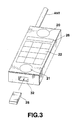
- FIG. 3 is a perspective view schematically showing the outward appearance of the PHS terminal 4 described above.
- the same structural elements as those of FIG. 2 are denoted by the same reference numerals and their descriptions are omitted.
- the speaker 20, display section 26, key-in section 22, and microphone 21 are provided on one face of the housing of the PHS terminal 4.
- a slot 32 into which the ID chip 28 is inserted is formed in the bottom portion of the housing.
- One end of the ID chip 28, which contacts the innermost of the slot, is provided with a terminal (not shown) fitted into the attachment/detachment detector of the interface 29.
- the detachable ID chip 28 can be attached to another PHS terminal 4, too.
- FIG. 4 is a block diagram showing a configuration of the ID chip 28 described above.
- the ID chip 28 includes a CPU 40, a ROM 41, a RAM 42, an EEPROM 43 and a connector 44.
- the CPU 40 executes communication control for transmitting/receiving various data items to/from the PHS terminal 4.
- the ROM 41 stores programs executed by the CPU 40.
- the RAM 42 is used as a work area when the programs are executed.
- the EEPROM 43 stores data as shown in FIG. 5.
- TELEPHONE NUMBER shows an area for storing callee's numbers used in originating calls and incoming calls
- SIMPLIFIED DIALING indicates an area for storing telephone directories and the like
- TRANSCEIVER CODE denotes an area for storing codes for peer-to-peer communication between terminals
- ALLS shows an area for storing information, such as extension numbers, call time, and charges, which is not included in the above three areas.
- the connector 44 has terminals for a reset signal, an SIO (Serial I/O) signal, a clock signal, a VCC signal and a ground signal.
- the reset signal is for resetting the CPU 40 of the ID chip 28.
- the SIO signal is a two-way data signal to transmit/receive data to/from the controller 23 of the PHS terminal 4.
- the clock signal is supplied to the CPU 40 in the ID chip 28.
- the VCC is a signal line for applying a power supply voltage.
- FIG. 6 is a schematic view of the configuration of the CS-ID.
- the CS-ID is 42 bits in total and includes a system calling code of 29 bits and an additional ID of 13 bits.
- the CS-ID is transmitted from the master 2 to the PHS terminal 4 by a predetermined operation and stored in the internal store (EEPROM 27) of the PHS terminal 4, with the result that the master 2 and PHS terminal 4 correspond to each other and they can intercommunicate with each other accordingly.
- the part (system calling code) of the CS-ID stored in the PHS terminal 4 is copied in a transceiver code area of the EEPROM 43 when a predetermined operation is performed in the PHS terminal 4 into which the IC chip 28 is inserted.
- the PHS terminal 4 discriminate between the transmission and reception sides by the controlling physical slot shown in FIG. 7 when a radio channel is.
- the physical slot is 240 bits in total, and includes a transition response ramp time R (4 bits), a start symbol SS (2 bits), a preamble PR (62 bits), a sync word UW (32 bits), a channel type CI (4 bits), a receiving identification code (42 bits), a calling identification code (28 bits), data I (34 bits), CRC (16 bits), and guard bits G (16 bits).
- the receiving and calling identification codes are relevant to the present invention.
- the 42-bit CS-ID as shown in FIG. 6 is written into an area of the receiving identification code
- 28-bit PS-ID for identification a terminal is written into an area of the calling identification code
- FIG. 7 shows an example of an up-link channel and, in a down-link channel, 42-bit CS-ID is the calling identification code and 28-bit PS-ID is the receiving identification code).
- the receiving identification code includes a system calling code (29 bits) for identifying the master, as described above, and a PS calling number (13 bits) for identifying the PHS terminal on the called or receiving side.
- the calling identification code includes a PS calling code (PS-ID) for identifying the PHS terminal on the calling side.
- PS-ID PS calling code
- the PS calling number is a logic number which is effective only for peer-to-peer communication between slaves.
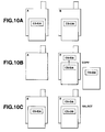
- a detachable memory is attached to a PHS terminal "A" as shown in FIG. 9A and the information necessary for the peer-to-peer communication between the PHS terminal "A” and another PHS terminal 4a, such as a system calling code (part of CS-ID) and a slave ID number (PS calling code) of the PHS terminal 4a is copied into the memory.
- the detachable memory into which a peer-to-peer communication information (CS-IDA) is copied is detached from the terminal "A" and attached to another PHS terminal "B".
- the PHS terminal "B” can communicate with the PHS terminal "A" in a peer-to-peer mode by selecting the peer-to-peer communication information stored in the detachable memory.
- a detachable memory storing the information necessary for the peer-to-peer communication with the PHS terminal "A”, such as a system calling code (part of CS-ID) and a slave ID number (PS calling code) of the PHS terminal "A” is attached to another PHS terminal "B", as shown in FIGS. 10A and 10B.
- the peer-to-peer communication information (CS-IDA) is copied into an internal memory of the PHS terminal "B".
- the PHS terminal "B” can communicate with the PHS terminal "A" in a peer-to-peer mode by selecting the peer-to-peer communication information stored in the internal memory.
- FIG. 11 is a flowchart showing a process of registering a system calling code (part of CS-ID) and a slave ID number (PS calling code) in the ID chip 28 from a predetermined PHS terminal.
- a message for urging an operator to input his or her password for example, a message "PLEASE INPUT PASSWORD" is displayed on the display section 26 in step S10.
- step S12 it is determined whether the password is input or not. If no password is input, the flow returns to step S10. If the password is input, the flow advances to step S14.
- step S14 it is determined whether the input password coincides with that stored in advance in the EEPROM 27. If they do not coincide, the flow returns to step S10. After that, steps S10 to S14 are repeated until the correct password is input. If it is not input even though the steps are repeated by a given number, the registration can be finished. If both the passwords are identical with each other, the flow advances to step S16.
- step S16 it is determined whether the ID chip 28 is inserted into the PHS terminal. If NO, the flow goes to step S18.
- step S18 a message for urging the operator to set the ID chip 28, for example, a message "PLEASE SET ID CHIP" is displayed on the display section 26, and the flow returns to step S16, where the terminal waits for the operator to set the ID chip 28. If the ID chip 28 is already inserted into the terminal or it is set according to the message, the flow advances to step S20.
- a message for urging the operator to set the ID chip 28 for example, a message "PLEASE SET ID CHIP" is displayed on the display section 26, and the flow returns to step S16, where the terminal waits for the operator to set the ID chip 28. If the ID chip 28 is already inserted into the terminal or it is set according to the message, the flow advances to step S20.
- step S20 a message for urging the operator to input a slave ID number, for example, a message "PLEASE INPUT SLAVE ID NUMBER" is displayed on the display section 26.
- step S22 it is determined whether the slave ID number is input or not.
- the slave ID number corresponds to the foregoing PS calling number and serves to call the PHS terminal on the receiving-side in peer-to-peer communication between terminals.
- the slave ID number is input by the key-in section 22, but can be assigned automatically on the base station 2 of the master. If the slave ID number is not input in step S22, the flow returns to step S16. After that, the steps S16 to S22 are repeated until the slave ID number is input. If the slave ID number is input in step S22, the flow advances to step S24.
- step S24 it is determined whether the slave ID number has been registered or not. If YES in step S24, the flow goes to step S26. In step S26, a message for informing the operator that the slave ID number has been registered, for example, a message "REGISTERED" is displayed on the display section 26. The flow returns to step S16.
- step S28 the system code and input slave ID number are transmitted to the ID chip 28 through the interface 29, and they are stored in the transceiver code area of the EEPROM 43.
- step S30 a message for informing the operator that input slave ID number is registered, for example, a message "SLAVE ID NUMBER N IS REGISTERED" is displayed on the display section 26. "N" indicates the actually-input slave ID number.
- step S32 it is determined whether the registration is completed or not. If NO, the flow returns to step S16. If YES, the registration ends.
- the ID chip 28 set in the PHS terminal 4 (for example, 4a) stores the system code for identifying the master 2 to which the PHS terminal 4 is previously registered and the slave ID number for identifying the PHS terminal (on the receiving side).
- the peer-to-peer communication can be performed between the PHS terminals 4a and 4b having different system codes which are previously registered, by selecting the peer-to-peer communication information stored in the ID chip 28 of the PHS terminal 4b.
- the second embodiment will be described hereinafter.
- the second embodiment can be realized by slightly modifying the first embodiment so that only different portions will be described with reference to the flowchart of the first embodiment shown in FIG. 11.
- the description is made for an example in which the system code stored in the ID chip 28 is copied into the EEPROM 27 of the PHS terminal 4.
- the ID chip 28 storing a system code of another master 2 is attached to the PHS terminal 4. If the registration mode is selected by using the key-input section 22, the flowchart shown in FIG. 11 starts.
- a message for urging an operator to input his or her password is displayed on the display section 26 and it is determined whether the input password coincides with that stored in the EEPROM 27 (steps S10, S12 and S14).
- step S16 it is determined whether the ID chip 28 is inserted into the PHS terminal.
- a message for urging the operator to set the ID chip 28 for example, a message "PLEASE SET ID CHIP" is displayed on the display section 26 (step S18).
- a message for urging the operator to input a slave ID number for example, a message "PLEASE INPUT SLAVE ID NUMBER" is displayed on the display section 26 (step S20).
- the flow advances step S22 and it is determined whether the slave ID number is input or not.
- the slave ID number corresponds to the foregoing PS calling number and serves to call the PHS terminal on the receiving-side in peer-to-peer communication between terminals.
- the slave ID number is input by the key-in section 22, but can be assigned automatically on the base station 2 of the master.
- step S24 it is determined whether the input slave ID number has been registered or not based on the slave ID number stored in the ID chip 28 (step S24). If YES in step S24, a message for informing the operator that the input slave ID number has been registered, for example, a message "REGISTERED" is displayed on the display section 26.
- the PHS terminal 4 reads out the system code and the slave ID number from the ID chip 28 and registered them into the internal EEPROM 27 (step S28).
- the input slave ID number is stored in the transceiver code area of the EEPROM 43.
- a message for informing the operator that input slave ID number is registered for example, a message "SLAVE ID NUMBER N IS REGISTERED" is displayed on the display section 26 (step S30). "N" indicates the actually-input slave ID number.
- step S32 it is determined whether the registration is completed or not. If YES, the registration ends.
- the system code for identifying another master 2 and the slave ID number which is previously registered in the master 2, both of which are stored in the ID chip 28 are copied into the EEPROM 27 of another PHS terminal 4 (for example, 4b) which is registered in the other master.
- the peer-to-peer communication can be performed between the PHS terminals 4a and 4b having different system codes which are previously registered, by selecting the peer-to-peer communication information stored in the ID chip 28 of the PHS terminal 4b.
- FIG. 12 is a conceptual view of a control sequence in peer-to-peer communication between PHS terminals in the system according to the present invention. Since the respective components of the PHS terminals, which are related to a call, are the same as those of the commonly-used PHS terminal, their operations are omitted.
- the system calling code is stored in the internal ROM 24 of the terminal and the ID chip 28. It is possible to select one of the internal ROM 24 aid the ID chip 28 based on a selection input from the key-in section 22 or a detection of setting the ID chip 28 to the terminal.
- a user determines which system calling code should be used (code selected by the user or code selected by the ID chip detection) and performs an operation of making a call by key-in section 22 in the calling-side PHS terminal 4a for peer-to-peer communication between terminals. Then, as shown in FIG. 8, the system calling code (29 bits) of the CS-ID stored in the terminal, the PS calling number of the receiving-side slave ID number, and the PS calling code for discriminating the calling-side PHS terminal are combined, and the combined data (calling signal in STEP 1) is transmitted by radio through the controlling physical slot shown in FIG. 7.
- the received system calling code and PS calling number of the physical slot and the system calling code and slave ID number stored in the ID chip 28 are compared, thereby recognizing that the terminal 4b is called. After that, sync words (sync signals in STEPS 2 and 3) are transmitted between the calling- and receiving-side PHS terminals 4a and 4b.
- the system calling code stored in the ID chip 28, the calling-side slave ID number (PS calling number), and the receiving-side slave ID number (PS calling code) are combined, and the combined data (response signal in STEP 4) is transmitted by radio to the calling-side PHS terminal 4a through the controlling physical slot shown in FIG. 7. Thereafter, an idle burst is transmitted between the calling- and receiving-side PHS terminals 4a and 4b (STEPS 5 and 6), and peer-to-peer communication between the terminals is started (STEP 7 et seq.).
- the peer-to-peer communication can be performed between PHS terminals even though these terminals are not registered in their common master.
- the maximum transmission time of the foregoing "calling signal” can be set to 10 seconds in consideration of battery saving on the receiving side.
- the "sync signal” can be canceled and the "response signal” can directly be returned in automatic response.
- the counting of transmission time can be started when the "calling signal” is transmitted and, in the receiving-side PHS terminal 4b, it can be started when the "sync signal" is transmitted.
- part of the CS-ID stored in the ID chip 28 cannot be used for a call between a terminal and its corresponding master 2 and, in other words, it is used only for peer-to-peer communication between terminals (transceiver communication); therefore, it need not be erased particularly. However, it can be erased automatically after a fixed period of time elapses or if a predetermined number of calls are made.
- a plurality of system calling codes can be stored in the ROM 24, the EEPROM 27 or the ID chip 28, and one of them for use can be selected by a certain method, e.g., by operating the key-in section 22. Since, in this case, the ID chip can be applied to a plurality of masters, the PHS terminals capable of peer-to-peer communication can be increased in number.
- the system calling code (e.g., CS-IDB of the communication terminal B) which is previously stored in the detachable memory (e.g., ID chip 28) can be stored in the internal memory of the radio terminal (e.g., the radio communication terminal B).
- a radio communication terminal has a detachable storing medium, this medium is set in an other radio communication terminal, and at least base station information necessary for peer-to-peer communication is stored in the medium, thereby obtaining the advantage that the peer-to-peer communication between the former terminal and the latter terminal, which is not registered in the master of the former terminal, can be performed.
Landscapes
- Engineering & Computer Science (AREA)
- Computer Networks & Wireless Communication (AREA)
- Signal Processing (AREA)
- Databases & Information Systems (AREA)
- Computer Security & Cryptography (AREA)
- Mobile Radio Communication Systems (AREA)
Abstract
Description
- The present invention relates to a radio communication system and a radio communication terminal for performing a radio communication between radio communication terminals having system codes.
- A radio communication system has recently been known to the public, which includes a radio communication terminal carried by a user, such as a portable telephone, a PHS (personal handy-phone system) terminal, a pager, and a PDA (personal digital assistant), for intercommunicating sound and data with another terminal including a commonly-used domestic telephone, and a base station connected to a communication network and communicating with the radio communication terminal to connect the terminal to the network.
- In this system, the radio communication terminal is driven by a secondary battery or the like such that it can be carried by a user, and capable of storing various types of data items such as callee's telephone numbers and addresses, schedule, and memorandum using characters and sound and transmitting/receiving information (sound, sound data, text data, image data, etc.) to/from another terminal through a telephone network.
- As one example of the radio communication system, there is a PHS which is currently put to practical use in Japan. The PHS will now be described for understanding of the radio communication system.
- A radio communication terminal of the PHS is employed as a slave of a master (base station) placed in a home. When the terminal is operated outdoors, it is also connected to a communication network through base stations (public and self-supporting stations) connected to the telephone network, with the result that it is allowed to intercommunicate with another terminal. If, furthermore, radio communication terminals are registered as slaves of their common master, peer-to-peer radio communication can be performed between the terminals but not through the base stations.
- In the peer-to-peer communication between the radio communication terminals, since the terminals necessitate a system code of their common master, all the terminals have to be brought to the master side for previous registration setting up the relation between the master and slave. In this registration, the slave ID numbers for discriminating the terminals are registered in the master, while a system calling code (part of CS-ID) for discriminating the master is registered in the slaves. In peer-to-peer radio communication between terminals, the system calling code and slave ID numbers are transmitted between the terminals, and it is determined based on the system calling code whether the peer-to-peer radio communication is possible or not. In other words, the peer-to-peer communication cannot be performed unless the system calling codes of the slaves are identical with that of the master.
- The above-described radio communication terminals have the following problem. In order to perform the peer-to-peer radio communication between the terminals, all the terminals have to be brought close to their common master and registered so as to correspond to the master. Therefore, the peer-to-peer radio communication cannot be done between a terminal and another terminal which is not registered in the master of the former one or between terminals which are registered in different masters.
- Accordingly, it is an object of the present invention to provide a radio communication system and a radio communication terminal capable of peer-to-peer communication between a radio communication terminal and another terminal which is not registered in the master of the former terminal.
- According to the present invention, there is provided a system connected to a communication network and having a system identification information, which comprises a storing medium, a first radio communication terminal having the same system identification information as the system and arranged for receiving the storing medium, and a second radio communication terminal arranged for receiving the storing medium, and in which the first radio communication terminal, when the storing medium is installed therein, copies the system identification information onto the storing medium, and the second radio communication terminal is allowed to communicate in peer-to-peer mode by a radio wave with the first communication terminal, when the storing medium on which the system identification information of the system is copied installed thereon.
- According to the present invention, there is provided another system connected to a communication network and having a system identification information, which comprises a storing medium having the system identification information, a first radio communication terminal having the same system identification information as the system and arranged for receiving the storing medium, and a second radio communication terminal arranged for receiving the storing medium, and in which a second radio communication terminal, when a detachable storing medium is set thereto, copies the system identification information of the storing medium into an internal memory of the second radio communication terminal, and is allowed to communicate in peer-to-peer mode by a radio wave with a first radio communication terminal based on the system identification information copied in the internal memory of the second radio communication terminal.
- According to the present invention, there is provided a still another system which comprises a storing medium, a first radio communication terminal having a same system identification information as the system and arranged for receiving the storing medium, and a second radio communication terminal arranged for receiving the storing medium, and in which the first radio communication terminal, when the storing medium is installed therein, copies the system identification information onto the storing medium, and the second radio communication terminal is allowed to communicate in peer-to-peer mode by a radio wave with the first communication terminal, when the storing medium on which the system identification information of the system is copied installed thereon.
- According to the present invention, there is provided a further system which comprises a storing medium having the system identification information, a first radio communication terminal having the same system identification information as the system and arranged for receiving the storing medium, and a second radio communication terminal arranged for receiving the storing medium, and in which the second radio communication terminal, when a detachable storing medium is set thereto, copies the system identification information of the storing medium into an internal memory of the second radio communication terminal, and is allowed to communicate in peer-to-peer mode by a radio wave with the first radio communication terminal based on the system identification information copied in the internal memory of the second radio communication terminal.
- According to the present invention, there is provided a further a system having a system identification information and connected to a communication network, terminal having the same system identification information as the system for communicating in a peer-to-peer mode with another radio communication terminal having the same system identification information. The radio communication terminal comprises a storing medium adapted to be detachably installed in the radio communication terminal, instruction means for outputting an instruction, and writing means for upon receipt of the instruction from the instruction means writing the system identification information of the radio communication terminal on the storing medium is installed on the radio communication terminal.
- According to the present invention, there is provided a further system connected to a communication network including a radio communication terminal having an original system identification information, for communicating in peer-to-peer mode with another radio communication terminal. The radio communication terminal comprises a storing medium adapted to be detachably installed in the radio communication terminal, for storing a system identification information, selecting means for, when the storing medium having a system identification information stored thereon is installed into the radio communication terminal, selecting any one of the original system identification information and the system identification information stored on the storing medium, and communication mean for communicating with another radio communication terminal based on the system identification information selected by the selecting means.
- According to the present invention, there is provided a further system having an original system identification information and connected to a communication network including a radio communication terminal for communicating in peer-to-peer mode with another radio communication. The radio communication terminal comprises first storing medium adapted to be detachably installed on the radio communication terminal, for storing a system identification information, a first internal memory for storing a system identification information, writing means for, when the storing medium is installed on the radio communication terminal, writing the system identification information stored in the first storing medium on the first internal memory, and communication means for communicating with another radio communication terminal based on the system identification information written on the internal memory by the writing means.
- According to the present invention, there is provided a further radio communication terminal having a system identification information as a system for communicating in a peer-to-peer mode with another radio communication terminal having the system identification information. The radio communication terminal comprises a storing medium adapted to be detachably installed in the radio communication terminal, instruction means for outputting an instruction, and writing means for upon receipt of the instruction from the instruction means writing the system identification information of the radio communication terminal on the storing medium is installed on the radio communication terminal.
- According to the present invention, there is provided a further radio communication terminal having an original system identification information, for communicating in peer-to-peer mode with another radio communication terminal, the radio communication terminal comprising a storing medium adapted to be detachably installed in the radio communication terminal, for storing a system identification information, selecting means for, when the storing medium having a system identification information stored thereon is installed into the radio communication terminal, selecting any one of the original system identification information and the system identification information stored on the storing medium, and communication means for communicating with another radio communication terminal based on the system identification information selected by the selecting means.
- According to the present invention, there is provided a further radio communication terminal for communicating in peer-to-peer mode with another radio communication, the radio communication terminal comprising first storing medium adapted to be detachably installed on the radio communication terminal, for storing a system identification information, a first internal memory for storing a system identification information, writing means for, when the storing medium is installed on the radio communication terminal, writing the system identification information stored in the first storing medium on the first internal memory, and communication means for communicating with another radio communication terminal based on the system identification information written on the internal memory by the writing means.
- The accompanying drawings, which are incorporated in and constitute a part of the specification, illustrate presently preferred embodiments of the present invention and, together with the general description given above and the detailed description of the preferred embodiments given below, serve to explain the principles of the present invention in which:
- FIG. 1 is a block diagram showing a configuration of a radio communication system such as a PHS terminal, according to the present invention;
- FIG. 2 is a block diagram showing a configuration of a PHS terminal of the system according to the embodiment of the present invention;
- FIG. 3 is a perspective view of the outward appearance of the PHS terminal of the system according to the embodiment of the present invention;
- FIG. 4 is a block diagram showing a configuration of an ID chip in the system according to the embodiment of the present invention;
- FIG. 5 is a conceptual view of data structure of EEPROM of the ID chip;
- FIG. 6 is a conceptual view of data structure of CS-ID in the system according to the embodiment of the present invention;
- FIG. 7 is a conceptual view of data structure of controlling physical slot SCCH in the system according to the embodiment of the present invention;
- FIG. 8 is a conceptual view of data structure of part of the controlling physical slot SCCH;
- FIGS. 9A and 9B schematically illustrate a first embodiment of the present invention;
- FIGS. 10A, 10B, and 10C schematically illustrate a second embodiment of the present invention;
- FIG. 11 is a flowchart showing a process of registering a peer-to-peer communication information in an IC chip in a system according to the first embodiment; and
- FIG. 12 is a conceptual view showing a control sequence in peer-to-peer communication between PHS terminals in the system according to the first embodiment.
- A preferred embodiment of a radio communication system according to the present invention will now be described with reference to the accompanying drawings. In the embodiment, the present invention is applied to a PHS terminal.
- FIG. 1 is a block diagram showing a configuration of a PHS system. The configuration of the PHS system is common to the first and second embodiments. In FIG. 1, reference numeral 1 indicates a nationwide normal analog telephone network or a dedicated digital network, which are generically called a communication network. A master (base station) 2 is connected to the communication network 1 and placed in a company, a home and the like in order to connect the network 1 with a
PHS terminal 4 by radio. Aradio base station 3 is connected to the communication network 1 and installed outdoors, in public facilities and the like to wirelessly connect the network 1 with thePHS terminal 4 which is carried outdoors and moved to public facilities or the like. - The
PHS terminal 4 is carried indoors or outdoors by a user, and makes a request to themaster 2 orbase station 3 for line connection by radio to communicate with another base station or another PHS terminal. As shown in FIG. 1, aPHS terminal 4a registered as a slave of themaster 2 is allowed to directly communicate (peer-to-peer communication) with aPHS terminal 4b which is not registered in the same master. - The
PHS terminal 4b is provided with anID chip 28 for storing information necessary for peer-to-peer communication between terminals, such as a system calling code for discriminating the slave when thePHS terminal 4a is registered in the master. Alternately, information necessary for peer-to-peer communication with theterminal 4a and stored in theID chip 28 is copied into an internal memory in theterminal 4b. As a result, based on the information stored in theID chip 28 or the information copied into the internal memory, peer-to-peer communication is performed between thePHS terminals ID chip 28 will be described later. - FIG. 2 is a block diagram showing a configuration of the
PHS terminal 4 described above. In FIG. 2, a transmitting/receiving section 10 includes a frequency converter having both areceiver 11 and atransmitter 12 and a modem (digital modulator/demodulator) 13 having a transmitting/receiving function. - The
receiver 11 mixes a signal, which is received by an antenna ANT and supplied through anantenna switch 14, with a local oscillation signal having a predetermined frequency output from aPLL synthesizer 15, to convert the received signal into an IF (intermediate frequency) signal whose frequency ranges from 1.9 GHz to about 1 MHz. - The
transmitter 12 mixes a modulated signal of π/4-shifted QPSK (quadrature phase shift keying), which is supplied from themodem 13, with a local oscillation signal having a predetermined frequency output from thePLL synthesizer 15, to convert the modulated signal into a signal having a frequency of 1.9 GHz and sends out the signal from the antenna ANT via theantenna switch 14. - In the receiver of the
modem 13, the IF signal from thereceiver 11 of the frequency converter is demodulated, the demodulated signal is divided into series of data items I and Q, and they are transmitted to a TDMA (Time Division Multiple Access)processor 16. In the transmitter of themodem 13, I and Q data are generated from data supplied from theTDMA processor 16 and modulated by π/4 shift QPSK, and the modulated data is supplied to thetransmitter 12 of the frequency converter. - The
TDMA processor 16 time-divides a radio frequency signal to execute TDMA processing for transmitting/receiving a signal in a burst way in a specific time zone. More specifically, on the reception side of theTDMA processor 16, data for one slot is taken out of the data supplied from themodem 13 in predetermined timing, and a unique word (sync signal) is extracted from the data to generate a frame sync signal. Then, a scramble of control data and sound data sections is canceled, and control and sound data is obtained from the format of the slot. Control data is sent to acontroller 23 and sound data is transmitted to a speech CODEC (Coder/Decoder) 17. On the transmission side of theprocessor 16, the control data is added to the sound data transmitted from thespeech CODEC 17 to generate transmission data. The scramble is added to the transmission data and then the unique word is added thereto to prepare transmission data for one slot. The transmission data is transmitted to themodem 13 in a predetermined timing or through a slot assigned thereto. - The
TDMA processor 16 is so operated that the signals transmitted from the master (base station) or slave (radio communication terminal, PHS terminal) do not collide at the same frequency in order to make them intercommunicate with each other. Each base station sends a signal to a time slot assigned in a frame and performs time position control (burst synchronization control) to prevent the signal from colliding with another signal. - The foregoing
speech CODEC 17 is designed to compress/extend digital data and constituted of a receiver section and a transmitter section. The receiver section extends an ADPCM sound signal (4 bits × 8 KHz = 32 Kbps), which is supplied from theTDMA processor 16, by decoding the ADPCM sound signal into a PCM sound signal (8 bits × 8 KHz = 64 Kbps), and sends the extended signal to aspeech conversion circuit 18. The transmitter section compresses the PCM sound signal, which is supplied from thespeech conversion circuit 18, by encoding the PCM sound signal into an ADPCM sound signal, and sends the compressed signal to theTDMA processor 16. - The
speech conversion circuit 18 is designed to convert an analog signal to a digital one, and vice versa. A receiver section of thecircuit 18 converts a PCM sound signal supplied from thespeech CODEC 17, into an analog sound signal to make a sound from aspeaker 20, while a transmitter section thereof converts an analog sound signal supplied from amicrophone 21, into a PCM signal and transmits it to thespeech CODEC 17. Thespeaker 20 andmicrophone 21 constitute a handset by connecting their handles to each other. - A key-in
section 22 includes numeral keys for inputting callee's telephone numbers, switches for on-hook and off-hook modes, and a volume switch for varying a sound level. The conditions of the keys and switches are supplied to thecontroller 23. Thecontroller 23 then controls the entire system in accordance with a predetermined program. - A
ROM 24 stores programs executed by thecontroller 23, various parameters such as CS-ID previously written by a communication service provider and the like, and aRAM 25 stores data generated according to a control operation of thecontroller 23 and serves as a work area. The data stored in theRAM 25 is maintained by a power supply such as a secondary battery (not shown). - A
display section 26 includes an LCD for displaying various types of data items such as operation modes, telephone numbers and call time, service menus offered by service companies, and the like, and an LED for showing ON and OFF states of a switch. Thedisplay section 26 is constituted of a touch panel in which the data items are displayed. If a user indicates (depresses) an icon or the like using or not using a touch pen (not shown), a function corresponding to the icon is performed. - An
EEPROM 27 stores a password for confirming whether the PHS terminal is used by a genuine user. In a second embodiment, the information necessary for peer-to-peer communication and stored in theID chip 28 is stored in theEEPROM 27, as described later. The password is input by a user in starting to use or operate the PHS terminal. The input password is compared with the password stored in theEEPROM 27. If they are identical with each other, it is determined that the user is a genuine one. - In order to discriminate between the master CS-ID (described later) and PHS terminal, a slave ID number and the like are stored in an
ID chip 28, which is detachable from the PHS terminal. The details of theID chip 28 will be described later. - An
interface 29 is provided to receive/transmit data from/to theID chip 28, and includes an attachment/detachment detector for detecting that theID chip 28 is attached to the PHS terminal. A result detected by the detector is supplied to thecontroller 23. Aringer 30 rings to inform a user of the received call or the like. - FIG. 3 is a perspective view schematically showing the outward appearance of the
PHS terminal 4 described above. In FIG. 3, the same structural elements as those of FIG. 2 are denoted by the same reference numerals and their descriptions are omitted. - Referring to FIG. 3, the
speaker 20,display section 26, key-insection 22, andmicrophone 21 are provided on one face of the housing of thePHS terminal 4. Aslot 32 into which theID chip 28 is inserted is formed in the bottom portion of the housing. One end of theID chip 28, which contacts the innermost of the slot, is provided with a terminal (not shown) fitted into the attachment/detachment detector of theinterface 29. As described above, thedetachable ID chip 28 can be attached to anotherPHS terminal 4, too. - FIG. 4 is a block diagram showing a configuration of the
ID chip 28 described above. As shown in FIG. 4, theID chip 28 includes aCPU 40, aROM 41, aRAM 42, anEEPROM 43 and aconnector 44. - The
CPU 40 executes communication control for transmitting/receiving various data items to/from thePHS terminal 4. TheROM 41 stores programs executed by theCPU 40. TheRAM 42 is used as a work area when the programs are executed. - The
EEPROM 43 stores data as shown in FIG. 5. In FIG. 5, "TELEPHONE NUMBER" shows an area for storing callee's numbers used in originating calls and incoming calls, "SIMPLIFIED DIALING" indicates an area for storing telephone directories and the like, "TRANSCEIVER CODE" denotes an area for storing codes for peer-to-peer communication between terminals, and "OTHERS" shows an area for storing information, such as extension numbers, call time, and charges, which is not included in the above three areas. - The
connector 44 has terminals for a reset signal, an SIO (Serial I/O) signal, a clock signal, a VCC signal and a ground signal. The reset signal is for resetting theCPU 40 of theID chip 28. The SIO signal is a two-way data signal to transmit/receive data to/from thecontroller 23 of thePHS terminal 4. The clock signal is supplied to theCPU 40 in theID chip 28. The VCC is a signal line for applying a power supply voltage. - Each
master 2 stores CS-ID for discriminating a master corresponding to thePHS terminal 4. FIG. 6 is a schematic view of the configuration of the CS-ID. The CS-ID is 42 bits in total and includes a system calling code of 29 bits and an additional ID of 13 bits. When amaster 2 is registered in itsslave PHS terminal 4, the CS-ID is transmitted from themaster 2 to thePHS terminal 4 by a predetermined operation and stored in the internal store (EEPROM 27) of thePHS terminal 4, with the result that themaster 2 andPHS terminal 4 correspond to each other and they can intercommunicate with each other accordingly. The part (system calling code) of the CS-ID stored in thePHS terminal 4 is copied in a transceiver code area of theEEPROM 43 when a predetermined operation is performed in thePHS terminal 4 into which theIC chip 28 is inserted. - In the radio communication (between a base station and a terminal or between terminals) according to the above-described embodiment, the
PHS terminal 4 discriminate between the transmission and reception sides by the controlling physical slot shown in FIG. 7 when a radio channel is. - As shown in FIG. 7, the physical slot is 240 bits in total, and includes a transition response ramp time R (4 bits), a start symbol SS (2 bits), a preamble PR (62 bits), a sync word UW (32 bits), a channel type CI (4 bits), a receiving identification code (42 bits), a calling identification code (28 bits), data I (34 bits), CRC (16 bits), and guard bits G (16 bits).
- Among them, the receiving and calling identification codes are relevant to the present invention. In the radio communication between the base station and terminal, the 42-bit CS-ID as shown in FIG. 6 is written into an area of the receiving identification code, and 28-bit PS-ID for identification a terminal is written into an area of the calling identification code (FIG. 7 shows an example of an up-link channel and, in a down-link channel, 42-bit CS-ID is the calling identification code and 28-bit PS-ID is the receiving identification code).
- In the radio communication between the terminals, as shown in FIG. 8, the receiving identification code includes a system calling code (29 bits) for identifying the master, as described above, and a PS calling number (13 bits) for identifying the PHS terminal on the called or receiving side. The calling identification code includes a PS calling code (PS-ID) for identifying the PHS terminal on the calling side. The PS calling number is a logic number which is effective only for peer-to-peer communication between slaves.
- An operation of the
PHS terminal 4 according to the above embodiment will now be described. - According to a first embodiment, a detachable memory is attached to a PHS terminal "A" as shown in FIG. 9A and the information necessary for the peer-to-peer communication between the PHS terminal "A" and another
PHS terminal 4a, such as a system calling code (part of CS-ID) and a slave ID number (PS calling code) of thePHS terminal 4a is copied into the memory. As shown in FIG. 9B, the detachable memory into which a peer-to-peer communication information (CS-IDA) is copied is detached from the terminal "A" and attached to another PHS terminal "B". As a result, the PHS terminal "B" can communicate with the PHS terminal "A" in a peer-to-peer mode by selecting the peer-to-peer communication information stored in the detachable memory. - According to a second embodiment, a detachable memory storing the information necessary for the peer-to-peer communication with the PHS terminal "A", such as a system calling code (part of CS-ID) and a slave ID number (PS calling code) of the PHS terminal "A" is attached to another PHS terminal "B", as shown in FIGS. 10A and 10B. The peer-to-peer communication information (CS-IDA) is copied into an internal memory of the PHS terminal "B". As a result, the PHS terminal "B" can communicate with the PHS terminal "A" in a peer-to-peer mode by selecting the peer-to-peer communication information stored in the internal memory.
- FIG. 11 is a flowchart showing a process of registering a system calling code (part of CS-ID) and a slave ID number (PS calling code) in the
ID chip 28 from a predetermined PHS terminal. - If a registration mode is selected by the key-in
section 22 of thePHS terminal 4, a message for urging an operator to input his or her password, for example, a message "PLEASE INPUT PASSWORD" is displayed on thedisplay section 26 in step S10. - In step S12, it is determined whether the password is input or not. If no password is input, the flow returns to step S10. If the password is input, the flow advances to step S14.
- In step S14, it is determined whether the input password coincides with that stored in advance in the
EEPROM 27. If they do not coincide, the flow returns to step S10. After that, steps S10 to S14 are repeated until the correct password is input. If it is not input even though the steps are repeated by a given number, the registration can be finished. If both the passwords are identical with each other, the flow advances to step S16. - In step S16, it is determined whether the
ID chip 28 is inserted into the PHS terminal. If NO, the flow goes to step S18. - In step S18, a message for urging the operator to set the
ID chip 28, for example, a message "PLEASE SET ID CHIP" is displayed on thedisplay section 26, and the flow returns to step S16, where the terminal waits for the operator to set theID chip 28. If theID chip 28 is already inserted into the terminal or it is set according to the message, the flow advances to step S20. - In step S20, a message for urging the operator to input a slave ID number, for example, a message "PLEASE INPUT SLAVE ID NUMBER" is displayed on the
display section 26. - In step S22, it is determined whether the slave ID number is input or not. The slave ID number corresponds to the foregoing PS calling number and serves to call the PHS terminal on the receiving-side in peer-to-peer communication between terminals.
- According to the embodiment of the present invention, the slave ID number is input by the key-in
section 22, but can be assigned automatically on thebase station 2 of the master. If the slave ID number is not input in step S22, the flow returns to step S16. After that, the steps S16 to S22 are repeated until the slave ID number is input. If the slave ID number is input in step S22, the flow advances to step S24. - In step S24, it is determined whether the slave ID number has been registered or not. If YES in step S24, the flow goes to step S26. In step S26, a message for informing the operator that the slave ID number has been registered, for example, a message "REGISTERED" is displayed on the
display section 26. The flow returns to step S16. - If the slave ID number has not yet been registered, the flow goes from step S24 to step S28. In step S28, the system code and input slave ID number are transmitted to the
ID chip 28 through theinterface 29, and they are stored in the transceiver code area of theEEPROM 43. - In step S30, a message for informing the operator that input slave ID number is registered, for example, a message "SLAVE ID NUMBER N IS REGISTERED" is displayed on the
display section 26. "N" indicates the actually-input slave ID number. - In step S32, it is determined whether the registration is completed or not. If NO, the flow returns to step S16. If YES, the registration ends.
- As described above, the
ID chip 28 set in the PHS terminal 4 (for example, 4a) stores the system code for identifying themaster 2 to which thePHS terminal 4 is previously registered and the slave ID number for identifying the PHS terminal (on the receiving side). - If a user removes the
ID chip 28 from thePHS terminal 4 and goes out and sets it in another PHS terminal (for example, 4b) which is not registered in themaster 2, the peer-to-peer communication can be performed between thePHS terminals ID chip 28 of thePHS terminal 4b. - The second embodiment will be described hereinafter. The second embodiment can be realized by slightly modifying the first embodiment so that only different portions will be described with reference to the flowchart of the first embodiment shown in FIG. 11. The description is made for an example in which the system code stored in the
ID chip 28 is copied into theEEPROM 27 of thePHS terminal 4. - The
ID chip 28 storing a system code of anothermaster 2 is attached to thePHS terminal 4. If the registration mode is selected by using the key-input section 22, the flowchart shown in FIG. 11 starts. - A message for urging an operator to input his or her password is displayed on the
display section 26 and it is determined whether the input password coincides with that stored in the EEPROM 27 (steps S10, S12 and S14). - When the correct password is input, it is determined whether the
ID chip 28 is inserted into the PHS terminal (step S16). - If the
ID chip 28 is not inserted, a message for urging the operator to set theID chip 28, for example, a message "PLEASE SET ID CHIP" is displayed on the display section 26 (step S18). - If the
ID chip 28 is already inserted into the terminal or it is set according to the message, a message for urging the operator to input a slave ID number, for example, a message "PLEASE INPUT SLAVE ID NUMBER" is displayed on the display section 26 (step S20). The flow advances step S22 and it is determined whether the slave ID number is input or not. - The slave ID number corresponds to the foregoing PS calling number and serves to call the PHS terminal on the receiving-side in peer-to-peer communication between terminals. According to the embodiment of the present invention, the slave ID number is input by the key-in
section 22, but can be assigned automatically on thebase station 2 of the master. - If the slave ID number is input by the user in accordance with the guidance message in step S22, it is determined whether the input slave ID number has been registered or not based on the slave ID number stored in the ID chip 28 (step S24). If YES in step S24, a message for informing the operator that the input slave ID number has been registered, for example, a message "REGISTERED" is displayed on the
display section 26. - If the slave ID number has not yet been registered, the
PHS terminal 4 reads out the system code and the slave ID number from theID chip 28 and registered them into the internal EEPROM 27 (step S28). In theID chip 28, the input slave ID number is stored in the transceiver code area of theEEPROM 43. - Then, a message for informing the operator that input slave ID number is registered, for example, a message "SLAVE ID NUMBER N IS REGISTERED" is displayed on the display section 26 (step S30). "N" indicates the actually-input slave ID number.
- In step S32, it is determined whether the registration is completed or not. If YES, the registration ends.
- As described above, the system code for identifying another
master 2 and the slave ID number which is previously registered in themaster 2, both of which are stored in theID chip 28 are copied into theEEPROM 27 of another PHS terminal 4 (for example, 4b) which is registered in the other master. As a result, the peer-to-peer communication can be performed between thePHS terminals ID chip 28 of thePHS terminal 4b. - Followings are the operation of the peer-to-peer communication using the peer-to-peer communication information registered in the first and second embodiments.
- FIG. 12 is a conceptual view of a control sequence in peer-to-peer communication between PHS terminals in the system according to the present invention. Since the respective components of the PHS terminals, which are related to a call, are the same as those of the commonly-used PHS terminal, their operations are omitted. In the above embodiments, the system calling code is stored in the
internal ROM 24 of the terminal and theID chip 28. It is possible to select one of theinternal ROM 24 aid theID chip 28 based on a selection input from the key-insection 22 or a detection of setting theID chip 28 to the terminal. - First, a user determines which system calling code should be used (code selected by the user or code selected by the ID chip detection) and performs an operation of making a call by key-in
section 22 in the calling-side PHS terminal 4a for peer-to-peer communication between terminals. Then, as shown in FIG. 8, the system calling code (29 bits) of the CS-ID stored in the terminal, the PS calling number of the receiving-side slave ID number, and the PS calling code for discriminating the calling-side PHS terminal are combined, and the combined data (calling signal in STEP 1) is transmitted by radio through the controlling physical slot shown in FIG. 7. In the receiving-side PHS terminal 4b, the received system calling code and PS calling number of the physical slot and the system calling code and slave ID number stored in theID chip 28 are compared, thereby recognizing that the terminal 4b is called. After that, sync words (sync signals inSTEPS 2 and 3) are transmitted between the calling- and receiving-side PHS terminals side PHS terminal 4b, the system calling code stored in theID chip 28, the calling-side slave ID number (PS calling number), and the receiving-side slave ID number (PS calling code) are combined, and the combined data (response signal in STEP 4) is transmitted by radio to the calling-side PHS terminal 4a through the controlling physical slot shown in FIG. 7. Thereafter, an idle burst is transmitted between the calling- and receiving-side PHS terminals - As described above, according to the foregoing embodiment, if a user goes out with the
ID chip 28 and sets it in a PHS terminal registered in another master, the peer-to-peer communication can be performed between PHS terminals even though these terminals are not registered in their common master. - The maximum transmission time of the foregoing "calling signal" can be set to 10 seconds in consideration of battery saving on the receiving side. In the receiving-
side PHS terminal 4b, the "sync signal" can be canceled and the "response signal" can directly be returned in automatic response. In the calling-side PHS terminal 4a, the counting of transmission time can be started when the "calling signal" is transmitted and, in the receiving-side PHS terminal 4b, it can be started when the "sync signal" is transmitted. - In the above-described embodiment, part of the CS-ID stored in the
ID chip 28 cannot be used for a call between a terminal and itscorresponding master 2 and, in other words, it is used only for peer-to-peer communication between terminals (transceiver communication); therefore, it need not be erased particularly. However, it can be erased automatically after a fixed period of time elapses or if a predetermined number of calls are made. - Furthermore, a plurality of system calling codes can be stored in the
ROM 24, theEEPROM 27 or theID chip 28, and one of them for use can be selected by a certain method, e.g., by operating the key-insection 22. Since, in this case, the ID chip can be applied to a plurality of masters, the PHS terminals capable of peer-to-peer communication can be increased in number. - Further, in the second embodiment of the present invention, the system calling code (e.g., CS-IDB of the communication terminal B) which is previously stored in the detachable memory (e.g., ID chip 28) can be stored in the internal memory of the radio terminal (e.g., the radio communication terminal B).
- As described above, according to the present invention, a radio communication terminal has a detachable storing medium, this medium is set in an other radio communication terminal, and at least base station information necessary for peer-to-peer communication is stored in the medium, thereby obtaining the advantage that the peer-to-peer communication between the former terminal and the latter terminal, which is not registered in the master of the former terminal, can be performed.
- Additional advantages and modifications will readily occur to those skilled in the art. Therefore, the present invention in its broader aspects is not limited to the specific details, representative devices, and illustrated examples shown and described herein. Accordingly, various modifications may be made without departing from the spirit or scope of the general inventive concept as defined by the appended claims and their equivalents.
Claims (32)
- A system (2) connected to a communication network (1) and having a system identification information, characterized by comprising:a storing medium (28);a first radio communication terminal (4a, A) having the same system identification information (CS-ID A) as said system (2) and arranged for receiving said storing medium (28); anda second radio communication terminal (4b, B) arranged for receiving said storing medium (28), and characterized in thatsaid first radio communication terminal (4a, A), when said storing medium (28) is installed therein, copies the system identification information (CS-ID A) onto said storing medium (28), andsaid second radio communication terminal (4b, B) is allowed to communicate in peer-to-peer mode by a radio wave with said first communication terminal (4a), when said storing medium (28) on which the system identification information of said system (2) is copied installed thereon.
- The system (2) according to claim 1, characterized in that said second radio communication terminal (4b, B) has a system identification information (CS-ID B) which is different from the system identification information of said system (2), and automatically switches, when said storing medium (28) on which the system identification information of said system (2) is copied is installed thereon, to the system identification information (CS-ID A) copied on said storing medium (28), to communicate in peer-to-peer mode by a radio wave with said first communication terminal (4a).
- The system according to claim 1, characterized in that said second radio communication terminal (4b, B) has an original system identification information (CS-ID B) which is different from the system identification information of said system (2), and comprises a selecting means adapted to be operated by a user for, when said storing medium (28) on which the system identification information of said system (2) is copied is installed thereon, selecting one of the original system identification information (CS-ID B) and the system identification information (CS-ID A) copied on said storing medium (28).
- The system according to claim 1, characterized in that said copying is allowed only when a correct password is input before said copying operation is carried out (steps S10, S12, and S14).
- A system (2) connected to a communication network (1) and having a system identification information, characterized by comprising:a storing medium (28) having the system identification information (CS-ID A);a first radio communication terminal having the same system identification information (CS-ID A) as said system (2) and arranged for receiving said storing medium (28); anda second radio communication terminal arranged for receiving said storing medium (28), and characterized in that said second radio communication terminal, when a detachable storing medium is set thereto, copies the system identification information (CS-ID A) of said storing medium (28) into an internal memory (27) of said second radio communication terminal, and is allowed to communicate in peer-to-peer mode by a radio wave with a first radio communication terminal (4a, A) based on the system identification information (CS-ID A) copied in the internal memory (27) of said second radio communication terminal.
- The system (2) according to claim 5, characterized in that said second radio communication terminal (B) has a system identification information (CS-ID B) which is different from the system identification information (CS-ID A) of said system (2), and automatically switches, when said internal memory (27) on which the system identification information of said system (2) is copied is installed thereon, to the system identification information (CS-ID A) copied on said internal memory (27), to communicate in peer-to-peer mode by a radio wave with said first communication terminal.
- The system (2) according to claim 5, characterized in that said second radio communication terminal (B) has an original system identification information (CS-ID B) which is different from the system identification information (CS-ID A) of said system (2), and comprises a selecting means adapted to be operated by a user for, when said internal memory (27) on which the system identification information of said system (2) is installed thereon, selecting one of the original system identification information (CS-ID B) and the system identification information (CS-ID A) copied on said internal memory (27).
- The system (2) according to claim 5, characterized in that said copying is allowed only when a correct password is input before said copying operation is carried out (steps S10, S12, and S14).
- A system (2) characterized by comprising:a storing medium (28);a first radio communication terminal (4a, A) having a same system identification information as said system (2) and arranged for receiving said storing medium (28); anda second radio communication terminal (4b, B) arranged for receiving said storing medium (28), and characterized in thatsaid first radio communication terminal (A), when said storing medium (28) is installed therein, copies the system identification information onto said storing medium (28), andsaid second radio communication terminal (4b, B) is allowed to communicate in peer-to-peer mode by a radio wave with said first communication terminal (A), when said storing medium on which the system identification information (CS-ID A) of said system (2) is copied installed thereon.
- The system (2) according to claim 9, characterized in that said second radio communication terminal (B) has a system identification information (CS-ID B) which is different from the system identification information (CS-ID A) of said system (2), and automatically switches, when said storing medium (28) on which the system identification information of said system (2) is copied is installed thereon, to the system identification information (CS-ID A) copied on said storing medium (28), to communicate in peer-to-peer mode by a radio wave with said first communication terminal (A).
- The system (2) according to claim 9, characterized in that said second radio communication terminal (B) has an original system identification information (CS-ID B) which is different from the system identification information (CS-ID A) of said system (2), and comprises a selecting means adapted to be operated by a use for, when said storing medium (28) on which the system identification information (CS-ID A) of said system (2) is copied is installed thereon, selecting one of the original system identification information (CS-ID B) and the system identification information (CS-ID A) copied on said storing medium (28).
- The system (2) according to claim 9, characterized in that said copying is allowed only when a correct password is input before said copying operation is carried out (steps S10, S12, and S14).
- A system (2) characterized by comprising:a storing medium (28) having the system identification information (CS-ID);a first radio communication terminal (A) having the same system identification information as said system (2) and arranged for receiving said storing medium; anda second radio communication terminal (B) arranged for receiving said storing medium, and characterized in that said second radio communication terminal (B), when a detachable storing medium is set thereto, copies the system identification information (CS-ID A) of said storing medium (28) into an internal memory (27) of said second radio communication terminal (B), and is allowed to communicate in peer-to-peer mode by a radio wave with said first radio communication terminal (A) based on the system identification information (CS-ID A) copied in the internal memory (27) of said second radio communication terminal (B).
- The system (2) according to claim 13, characterized in that said second radio communication terminal (B) has a system identification information (CS-ID B) which is different from the system identification information (CS-ID A) of said system (2), and automatically switches, when said internal memory (27) on which the system identification information (CS-ID A) of said system (2) is copied is installed thereon, to the system identification information (CS-ID A) copied on said internal memory (27), to communicate in peer-to-peer mode by a radio wave with said first communication terminal (A).
- The system (2) according to claim 13, characterized in that said second radio communication terminal (B) has an original system identification information (CS-ID B) which is different from the system identification information (CS-ID A) of said system (2), and comprises a selecting means adapted to be operated by a user for, when said internal memory on which the system identification information (CS-ID A) of said system (2) is installed thereon, selecting one of the original system identification information (CS-ID B) and the system identification information (CS-ID A) copied on said internal memory.
- The system (2) according to claim 13, characterized in that said copying is allowed only when a correct password is input before said copying operation is carried out (steps S10, S12, and S14).
- In a system (2) having a system identification information and connected to a communication network (1), a radio communication terminal (4) having the same system identification information as the system (2) for communicating in a peer-to-peer mode with another radio communication terminal (4) having the same system identification information, characterized by comprising:a storing medium (28) adapted to be detachably installed in said radio communication terminal (A);instruction means (22) for outputting an instruction; andwriting means (23) for upon receipt of the instruction from said instruction means (22) writing the system identification information of said radio communication terminal on said storing medium (28) is installed on said radio communication terminal (A).
- The radio communication terminal (4) according to claim 17, characterized by further comprising:inputting means (22) for inputting a password;comparing means (23) for comparing an input password with a predetermined password;means (23) for allowing said writing means to execute writing operation when the input password coincides with the predetermined password.
- In a system (2) connected to a communication network (1) including a radio communication terminal (4) having an original system identification information (CS-ID), for communicating in peer-to-peer mode with another radio communication terminal (4), characterized by comprising:a storing medium (28) adapted to be detachably installed in said radio communication terminal (4), for storing a system identification information (CS-ID);selecting means (23) for, when said storing medium (28) having a system identification information (CS-ID) stored thereon is installed into said radio communication terminal (4), selecting any one of the original system identification information (CS-ID B) and the system identification information (CS-ID A) stored on said storing medium; andcommunication means (23) for communicating with another radio communication terminal (4) based on the system identification information (CS-ID) selected by said selecting means (23).
- The radio communication terminal (4) according to claim 19, characterized in that said selecting means (23) automatically selects any one of the original system identification information (CS-ID B) and the system identification information (CS-ID A) stored on said storing medium (28) when said storing medium (28) is installed on said radio communication terminal (4).
- The radio communication terminal (4) according to claim 19, characterized by further comprising:control means (22) externally operable by a user, for controlling said selecting means (23) to select any one of the original system identification information (CS-ID B) and the system identification information (CS-ID A) stored on said storing medium (28).
- In a system (2) having an original system identification information and connected to a communication network (1) including a radio communication terminal (4) for communicating in peer-to-peer mode with another radio communication, characterized by comprising:a first storing medium adapted to be detachably installed on said radio communication terminal (4a, A), for storing a system identification information (CS-ID A);a first internal memory (27) for storing a system identification information;writing means (23) for, when said storing medium (28) is installed on said radio communication terminal, writing the system identification information (CS-ID A) stored in said first storing medium on said first internal memory (27); andcommunication means (23) for communicating with another radio communication terminal based on the system identification information written on said internal memory (27) by said writing means (23).
- The radio communication terminal (4) according to claim 22, characterized by further comprising:a second internal memory (24) for storing the original system identification information (CS-ID B); andselecting means (23) for selecting one of the original system identification information (CS-ID B) stored in said second internal memory (24) and the system identification information (CS-ID A) written on said first internal memory (27) by said writing means (23), and characterized in that said communication means (23) communicates with another radio communication terminal based on the system identification information (CS-ID A) selected by said selecting means (23).
- The radio communication terminal (4) according to claim 22, characterized by further comprising:a second storing medium stores the original system identification information (CS-ID B) of said system (2); andselecting means (23) for, when said second storing medium is installed on said radio communication terminal (B), selecting one of the original system identification information (CS-ID B) of said system (2) stored on said second storing medium and the system identification information (CS-ID A) previously written on said first internal memory (27) by said writing means (23), and characterized in that said communication means (23) communicates with another radio communication terminal (4) based on the system identification information (CS-ID A) selected by said selecting means (23).
- A radio communication terminal (4) having a system identification information (CS-ID) as a system (2) for communicating in a peer-to-peer mode with another radio communication terminal (4) having the system identification information (CS-ID), characterized by comprising:a storing medium (28) adapted to be detachably installed in said radio communication terminal (4);instruction means (22) for outputting an instruction; andwriting means (23) for upon receipt of the instruction from said instruction means (22) writing the system identification information of said radio communication terminal (4) on said storing medium (28) is installed on said radio communication terminal (4).
- The radio communication terminal (4) according to claim 25, characterized by further comprising:inputting means (22) for inputting a password;comparing means (23) for comparing an input password with a predetermined password; andmeans (23) for allowing said writing means (23) to execute writing operation when the input password coincides with the predetermined password.
- A radio communication terminal (4) having an original system identification information (CS-ID B), for communicating in peer-to-peer mode with another radio communication terminal (4), characterized by comprising:a storing medium (28) adapted to be detachably installed in said radio communication terminal (4), for storing a system identification information (CS-ID A);selecting means (23) for, when said storing medium (28) having a system identification information (CS-ID A) stored thereon is installed into said radio communication terminal (4), selecting any one of the original system identification information (CS-ID B) and the system identification information (CS-ID A) stored on said storing medium (28); andcommunication means (23) for communicating with another radio communication terminal based on the system identification information (CS-ID) selected by said selecting means (23).
- The radio communication terminal (4) according to claim 27, characterized in that said selecting means (23) automatically selects any one of when said storing medium (28) is installed on said radio communication terminal (4).
- The radio communication terminal (4) according to claim 27, characterized by further comprising:control means (22) externally operable by a user, for controlling said selecting means (23) to select any one of the original system identification information (CS-ID B) and the system identification information (CS-ID A) stored on said storing medium (28).
- A radio communication terminal (4) for communicating in peer-to-peer mode with another radio communication (4), characterized by comprising:first storing medium adapted to be detachably installed on said radio communication terminal (4), for storing a system identification information (CS-ID A);a first internal memory (27) for storing a system identification information (CS-ID);writing means (23) for, when said storing medium is installed on said radio communication terminal (A), writing the system identification information (CS-ID A) stored in said first storing medium on said first internal memory (27); andcommunication means (23) for communicating with another radio communication terminal (4) based on the system identification information (CS-ID) written on said internal memory (27) by said writing means (23).
- The radio communication terminal (4) according to claim 30, characterized by comprising:a second internal memory (24) for storing the original system identification information (CS-ID); andselecting means (23) for selecting any one of the original system identification information (CS-ID) stored in said second internal memory (24) and the system identification information (CS-ID) written on said first internal memory (27) by said writing means (23), and characterized in that said communication means (23) communicates with another radio communication terminal (4) based on the system identification information (CS-ID) selected by said selecting means (23).
- The radio communication terminal (4) according to claim 30, characterized by further comprising:a second storing medium stores the original system identification information (CS-ID B) of said system (2); andselecting means (23) for, when said second storing medium installed on said radio communication terminal (B), selecting any one of the original system identification information (CS-ID B) of said system (2) stored on said second storing medium and the system identification information (CS-ID A) previously written on said first internal memory (27) by said writing means (23), and characterized in that said communication means (23) communicates with another radio communication terminal (A) based on the system identification information (CS-ID) selected by said selecting means (23).
Applications Claiming Priority (3)
| Application Number | Priority Date | Filing Date | Title |
|---|---|---|---|
| JP116419/95 | 1995-04-18 | ||
| JP11641995 | 1995-04-18 | ||
| JP11641995 | 1995-04-18 |
Publications (2)
| Publication Number | Publication Date |
|---|---|
| EP0739149A2 true EP0739149A2 (en) | 1996-10-23 |
| EP0739149A3 EP0739149A3 (en) | 1999-11-17 |
Family
ID=14686621
Family Applications (1)
| Application Number | Title | Priority Date | Filing Date |
|---|---|---|---|
| EP96106118A Withdrawn EP0739149A3 (en) | 1995-04-18 | 1996-04-18 | Radio communication system and radio communication terminal |
Country Status (7)
| Country | Link |
|---|---|
| US (1) | US5909652A (en) |
| EP (1) | EP0739149A3 (en) |
| KR (1) | KR100223037B1 (en) |
| CN (1) | CN1081878C (en) |
| HK (1) | HK1002217A1 (en) |
| MY (1) | MY132184A (en) |
| SG (1) | SG47126A1 (en) |
Cited By (6)
| Publication number | Priority date | Publication date | Assignee | Title |
|---|---|---|---|---|
| DE19704907A1 (en) * | 1997-02-10 | 1997-07-31 | Andre Bornholt | Mobile radio telephone with direct communication capability |
| DE19745350C1 (en) * | 1997-02-10 | 1998-08-20 | Kunze Ingeburg | Mobile radio telephone for multi-mode operation and use of a relay station for such mobile radio telephones |
| GB2378619A (en) * | 2001-07-24 | 2003-02-12 | Hewlett Packard Co | Monitoring transmissions to connect remote cellular devices |
| EP1355474A1 (en) * | 2001-01-25 | 2003-10-22 | Sony Computer Entertainment Inc. | Method for exchanging information between communication devices capable of carrying out radio communication |
| US6728553B1 (en) | 1997-01-27 | 2004-04-27 | Sonera Oy | Subscriber identity module mobile station and method for performing a smart card function |
| WO2004054218A1 (en) * | 2002-12-12 | 2004-06-24 | Koninklijke Philips Electronics N.V. | Device for securely transferring data between electronic units |
Families Citing this family (9)
| Publication number | Priority date | Publication date | Assignee | Title |
|---|---|---|---|---|
| JP3056080B2 (en) * | 1996-07-31 | 2000-06-26 | 埼玉日本電気株式会社 | Mobile phone |
| SG118132A1 (en) | 1997-11-13 | 2006-01-27 | Hyperspace Communications Inc | File transfer system |
| US6195568B1 (en) * | 1998-02-24 | 2001-02-27 | Ericsson Inc. | Radiotelephone adapted to the identity of its user |
| KR100715936B1 (en) * | 1999-05-12 | 2007-05-11 | 주식회사 아이디어파크 | Handphone having transmssion function of voice/letter of a short distance |
| US7142812B1 (en) * | 2000-06-13 | 2006-11-28 | Sony Deutschland Gmbh | Wireless transmission system |
| US6704566B1 (en) * | 2000-10-20 | 2004-03-09 | Motorola, Inc. | Communication device for placing calls within a plurality of wireless communication networks |
| US20040003136A1 (en) * | 2002-06-27 | 2004-01-01 | Vocollect, Inc. | Terminal and method for efficient use and identification of peripherals |
| CN100473215C (en) * | 2004-01-16 | 2009-03-25 | Ut斯达康通讯有限公司 | Improved paging method in personal mobile hand-set system and relative equipment |
| US20080172545A1 (en) * | 2007-01-12 | 2008-07-17 | John Christian Boucard | System and method for accessing and displaying interactive content and advertising |
Citations (5)
| Publication number | Priority date | Publication date | Assignee | Title |
|---|---|---|---|---|
| EP0538014A2 (en) * | 1991-10-16 | 1993-04-21 | Kabushiki Kaisha Toshiba | Radio telecommunication apparatus with a plurality of system identification informations |
| US5212809A (en) * | 1988-09-06 | 1993-05-18 | Seiko Instruments Inc. | Radio communication system |
| GB2270442A (en) * | 1992-09-04 | 1994-03-09 | Motorola Inc | Information transfer between radio telephone and portable memory element |
| DE4321381A1 (en) * | 1993-06-26 | 1995-01-05 | Sel Alcatel Ag | Apparatus and method for exchanging or amending software in devices |
| WO1995004425A1 (en) * | 1993-07-30 | 1995-02-09 | Ericsson Ge Mobile Communications Inc. | Method and apparatus for upgrading cellular mobile telephones |
Family Cites Families (10)
| Publication number | Priority date | Publication date | Assignee | Title |
|---|---|---|---|---|
| DE3036380A1 (en) * | 1980-09-26 | 1982-05-13 | Siemens AG, 1000 Berlin und 8000 München | COMMUNICATION SYSTEM, ESPECIALLY TELEPHONE SYSTEM |
| JPH0787493B2 (en) * | 1986-05-23 | 1995-09-20 | 日本電信電話株式会社 | Card access telephone |
| US5020105A (en) * | 1986-06-16 | 1991-05-28 | Applied Information Technologies Corporation | Field initialized authentication system for protective security of electronic information networks |
| JPH087720B2 (en) * | 1986-09-16 | 1996-01-29 | 富士通株式会社 | Area access method for IC cards for multiple services |
| US4992926A (en) * | 1988-04-11 | 1991-02-12 | Square D Company | Peer-to-peer register exchange controller for industrial programmable controllers |
| GB2241133A (en) * | 1990-02-14 | 1991-08-21 | Motorola Inc | Radiotelephone having removable memory means for storing radio user validation code |
| JPH07235981A (en) * | 1993-12-28 | 1995-09-05 | Casio Comput Co Ltd | Cordless telephone system and slave machine extension method in cordless telephone system |
| US5497411A (en) * | 1994-03-14 | 1996-03-05 | Pellerin; Joseph C. E. | Telecommunications card-access system |
| US5675628A (en) * | 1994-08-01 | 1997-10-07 | Nokia Telecommunications Oy | Method and apparatus for enabling roaming of subscriber among plural mobile radio systems, using mobile equipment accepting removable subscriber identity module |
| US5511232A (en) * | 1994-12-02 | 1996-04-23 | Motorola, Inc. | Method for providing autonomous radio talk group configuration |
-
1996
- 1996-04-16 US US08/632,905 patent/US5909652A/en not_active Expired - Fee Related
- 1996-04-17 KR KR1019960011597A patent/KR100223037B1/en not_active IP Right Cessation
- 1996-04-17 MY MYPI96001454A patent/MY132184A/en unknown
- 1996-04-17 SG SG1996009334A patent/SG47126A1/en unknown
- 1996-04-18 CN CN96104638A patent/CN1081878C/en not_active Expired - Fee Related
- 1996-04-18 EP EP96106118A patent/EP0739149A3/en not_active Withdrawn
-
1998
- 1998-02-06 HK HK98100910A patent/HK1002217A1/en not_active IP Right Cessation
Patent Citations (5)
| Publication number | Priority date | Publication date | Assignee | Title |
|---|---|---|---|---|
| US5212809A (en) * | 1988-09-06 | 1993-05-18 | Seiko Instruments Inc. | Radio communication system |
| EP0538014A2 (en) * | 1991-10-16 | 1993-04-21 | Kabushiki Kaisha Toshiba | Radio telecommunication apparatus with a plurality of system identification informations |
| GB2270442A (en) * | 1992-09-04 | 1994-03-09 | Motorola Inc | Information transfer between radio telephone and portable memory element |
| DE4321381A1 (en) * | 1993-06-26 | 1995-01-05 | Sel Alcatel Ag | Apparatus and method for exchanging or amending software in devices |
| WO1995004425A1 (en) * | 1993-07-30 | 1995-02-09 | Ericsson Ge Mobile Communications Inc. | Method and apparatus for upgrading cellular mobile telephones |
Cited By (9)
| Publication number | Priority date | Publication date | Assignee | Title |
|---|---|---|---|---|
| US6728553B1 (en) | 1997-01-27 | 2004-04-27 | Sonera Oy | Subscriber identity module mobile station and method for performing a smart card function |
| DE19704907A1 (en) * | 1997-02-10 | 1997-07-31 | Andre Bornholt | Mobile radio telephone with direct communication capability |
| DE19707833A1 (en) * | 1997-02-10 | 1997-10-09 | Andre Bornholt | Use of relay stations for mobile phones to set up a local network |
| DE19745350C1 (en) * | 1997-02-10 | 1998-08-20 | Kunze Ingeburg | Mobile radio telephone for multi-mode operation and use of a relay station for such mobile radio telephones |
| EP1355474A1 (en) * | 2001-01-25 | 2003-10-22 | Sony Computer Entertainment Inc. | Method for exchanging information between communication devices capable of carrying out radio communication |
| EP1355474A4 (en) * | 2001-01-25 | 2008-04-16 | Sony Computer Entertainment Inc | Method for exchanging information between communication devices capable of carrying out radio communication |
| GB2378619A (en) * | 2001-07-24 | 2003-02-12 | Hewlett Packard Co | Monitoring transmissions to connect remote cellular devices |
| GB2378619B (en) * | 2001-07-24 | 2005-09-14 | Hewlett Packard Co | Cellular apparatus and method for transmitting cellular signals |
| WO2004054218A1 (en) * | 2002-12-12 | 2004-06-24 | Koninklijke Philips Electronics N.V. | Device for securely transferring data between electronic units |
Also Published As
| Publication number | Publication date |
|---|---|
| MY132184A (en) | 2007-09-28 |
| HK1002217A1 (en) | 1998-08-07 |
| US5909652A (en) | 1999-06-01 |
| KR960040052A (en) | 1996-11-25 |
| KR100223037B1 (en) | 1999-10-01 |
| EP0739149A3 (en) | 1999-11-17 |
| CN1081878C (en) | 2002-03-27 |
| CN1158062A (en) | 1997-08-27 |
| SG47126A1 (en) | 1998-03-20 |
Similar Documents
| Publication | Publication Date | Title |
|---|---|---|
| US5909652A (en) | Radio communication system and radio communication terminal | |
| US5590397A (en) | Selecting and prioritizing radio telephone systems at radio terminal | |
| KR920005906B1 (en) | Radio telecommunication apparatus | |
| US5371782A (en) | Method and apparatus for selecting a preferred service provider during a call setup in a public cordless telephone system | |
| WO1993016548A1 (en) | Apparatus and method for alternative radiotelephone system selection | |
| WO1993016560A1 (en) | Dual system cellular cordless radiotelephone apparatus and method | |
| US6108543A (en) | Radio communication apparatus connected with a base station used in a service area prior to the others | |
| US5509047A (en) | Portable radio telephone and method for selecting radio channel of cheap fee | |
| JPH08294168A (en) | Radio communication system and radio communication terminal | |
| EP0538014A2 (en) | Radio telecommunication apparatus with a plurality of system identification informations | |
| GB2297461A (en) | Cordless telephone which can register with a plurality of base stations | |
| KR19980087303A (en) | Receiver device and receiving channel setting method | |
| US6477383B1 (en) | Communication system having a notification function with respect to a predetermined state of each communication terminal thereof | |
| KR19990082058A (en) | Telecommunication Systems, Channel Selection Protocols, and Wireless Stations | |
| JP2885648B2 (en) | Wireless terminal | |
| JP2005102268A (en) | Display system for communication apparatus | |
| JPH08322087A (en) | Radio communication terminal | |
| JP2609665B2 (en) | Registration method of identification information of wireless telephone system | |
| JP3048765B2 (en) | Digital cordless telephone | |
| JPH099359A (en) | Radio communication system and radio communication terminal equipment | |
| JPH0613968A (en) | Portable telephone set and radio channel designation method | |
| JPH0746662A (en) | Digital cordless telephone system | |
| KR19980072498A (en) | Auto mode switching method for portable wireless communication terminal for home and public use | |
| JPH09153952A (en) | Remote control method by mobile terminal and controller for the method | |
| JPH08289370A (en) | Base station and communication terminal in communication system |
Legal Events
| Date | Code | Title | Description |
|---|---|---|---|
| PUAI | Public reference made under article 153(3) epc to a published international application that has entered the european phase |
Free format text: ORIGINAL CODE: 0009012 |
|
| 17P | Request for examination filed |
Effective date: 19960418 |
|
| AK | Designated contracting states |
Kind code of ref document: A2 Designated state(s): DE FR GB IT |
|
| RAP1 | Party data changed (applicant data changed or rights of an application transferred) |
Owner name: CASIO COMPUTER CO., LTD. |
|
| PUAL | Search report despatched |
Free format text: ORIGINAL CODE: 0009013 |
|
| AK | Designated contracting states |
Kind code of ref document: A3 Designated state(s): DE FR GB IT |
|
| 17Q | First examination report despatched |
Effective date: 20001207 |
|
| GRAG | Despatch of communication of intention to grant |
Free format text: ORIGINAL CODE: EPIDOS AGRA |
|
| GRAG | Despatch of communication of intention to grant |
Free format text: ORIGINAL CODE: EPIDOS AGRA |
|
| GRAH | Despatch of communication of intention to grant a patent |
Free format text: ORIGINAL CODE: EPIDOS IGRA |
|
| GRAG | Despatch of communication of intention to grant |
Free format text: ORIGINAL CODE: EPIDOS AGRA |
|
| GRAH | Despatch of communication of intention to grant a patent |
Free format text: ORIGINAL CODE: EPIDOS IGRA |
|
| GRAH | Despatch of communication of intention to grant a patent |
Free format text: ORIGINAL CODE: EPIDOS IGRA |
|
| STAA | Information on the status of an ep patent application or granted ep patent |
Free format text: STATUS: THE APPLICATION HAS BEEN WITHDRAWN |
|
| 18W | Application withdrawn |
Withdrawal date: 20020228 |
|
| REG | Reference to a national code |
Ref country code: HK Ref legal event code: WD Ref document number: 1013582 Country of ref document: HK |