EP0741199A2 - Automatic cop changing device for a weaving machine - Google Patents
Automatic cop changing device for a weaving machine Download PDFInfo
- Publication number
- EP0741199A2 EP0741199A2 EP96109170A EP96109170A EP0741199A2 EP 0741199 A2 EP0741199 A2 EP 0741199A2 EP 96109170 A EP96109170 A EP 96109170A EP 96109170 A EP96109170 A EP 96109170A EP 0741199 A2 EP0741199 A2 EP 0741199A2
- Authority
- EP
- European Patent Office
- Prior art keywords
- cop
- weft
- shuttle
- changing device
- tying
- Prior art date
- Legal status (The legal status is an assumption and is not a legal conclusion. Google has not performed a legal analysis and makes no representation as to the accuracy of the status listed.)
- Granted
Links
Images
Classifications
-
- D—TEXTILES; PAPER
- D03—WEAVING
- D03D—WOVEN FABRICS; METHODS OF WEAVING; LOOMS
- D03D45/00—Looms with automatic weft replenishment
- D03D45/20—Changing bobbins, cops, or other shuttle stock
Landscapes
- Engineering & Computer Science (AREA)
- Textile Engineering (AREA)
- Looms (AREA)
- Knitting Machines (AREA)
- Replacing, Conveying, And Pick-Finding For Filamentary Materials (AREA)
- Auxiliary Weaving Apparatuses, Weavers' Tools, And Shuttles (AREA)
- Yarns And Mechanical Finishing Of Yarns Or Ropes (AREA)
Abstract
Description
- The present invention relates to a device for changing cops for a weaving machine in which a shuttle detachably carrying a cop consisting of a wooden bobbin having a weft wound thereon is reciprocated laterally between warps, and in particular to an automatic cop changing device for a weaving machine which can automatically carry out a series of actions including the action of positioning the shuttle at a prescribed location, the action of tying the weft of the current cop which has been used up by more than a prescribed amount with the weft of a next new cop, and the action of removing the current cop from the shuttle and mounting the next cop on the shuttle.
- For instance, in a paper making machine, water is removed from wet pulp by pressing it between a pair of opposing rollers, and such rollers consist of press felt in the form of relatively broad endless belts. The press felt is made by entangling fibers of a pad consisting of layers of woolen or synthetic fiber web with a ground fabric by needling. During the weaving process of the ground fabric, the warps are set on a warp beam and fed continuously while the weft is supplied by a cop mounted on a shuttle. Therefore, when weaving such a broad ground fabric for making press felt, the cop is required to be changed to a new one every time the shuttle has reciprocated from one lateral end to the other by a certain number of times. Further, at the same time, the weft of the old cop and the weft of the new cop must be connected with each other by welding or the like.
- Conventionally, changing cops and connecting the ends of two wefts together were carried out manually.
- As a result, an experienced operator was required for each weaving machine, and it was difficult to reduce the cost of weaving.
- US-A-3,608,589 discloses a structure for changing pirns in a weaving machine. According to this patent, the pirn is lifted from the shuttle by the jaws mounted on the transfer head which can rotate around a horizontal axial line, and is placed in a position above the shuttle after it is used up. The pirn maintains its horizontal attitude throughout this process. This severely restricts the placement of the means for storing the pirns.
- Further, according to this prior art publication, the wire extending from the used pirn and the wire extending from the new pirn are both drawn by transferring the pirns, and passing the wire through a wire knotting station as the pirns are being transferred. A forked lever draws the wire, and controls the slack of the wire by passing it around a stripper. The wire is handled by the forked lever and other related parts. Thus, the apparatus requires two separate arms to remove the pirn from the shuttle and to handle the wire, and the resulting structure is necessarily complex.
- In view of such problems of the prior art, a primary object of the present invention is to provide a device for automatically changing cops for a weaving machine which is adapted to be automated.
- A second object of the present invention is provide a device for changing cops for a weaving machine which is simple in structure so as to be economical to fabricate and free from failures during its operation.
- A third object to the present invention is to provide such a cop changing device which is compact enough to be incorporated into an existing weaving machine designed for manual replacement of cops.
- A fourth object of the present invention is provide such a cop changing device which can replace cops with minimum time and can reduce the chance of weft breakage at the same time.
- According to the present invention there is provided an automatic cop changing device for a weaving machine in which a shuttle (2) carrying a cop (19) consisting of a bobbin (21) around which a weft (4) is wound is reciprocated between warps (3) so as to weave said weft between said warps, comprising :
- cop positioning means (13, 14, 22) for keeping said shuttle stationary near a terminal point of its reciprocating movement when the weft of a current cop mounted on said shuttle is consumed by more than a prescribed amount;
- cop storage means (44)
- weft pulling means (24, 26, 28) for drawing the weft from said current cop and a weft from of said new cops stored in said cop storage means, and crossing said two wefts;
- weft tying means (47) for tying said crossed part of said wefts;
- weft trimming means (57) for trimming an extraneous part of said tied weft; and
- cop replacing means (24, 26, 27, 29) for removing said current cop from said shuttle, and mounting said new cop on said shuttle; characterized in that:
- said cop replacing means comprises a robot arm having a cop raising hand (24) for moving a cop between a retracted position in said shuttle and an upright position in said shuttle, and a cop gripping hand (27) for gripping a cop and carrying it between its upright position in said shuttle and its storage position in said cop storage means; and
- said cop storage means (44) is capable of storing a plurality of new cops (43).
- Thus by positioning the shuttle, drawing out the weft from the cop which has been used up by more than a prescribed amount, tying it with the weft of the next cop which is stored in the storage means, and changing the cop with the cop replacing means for expelling the old cop from the shuttle and mounting the next cop on the shuttle, it is possible to eliminate the need for an operator always attending the weaving machine. The tying means may consist of an ultrasonic, high frequency or other welding unit.
- Preferably, the device is equipped with slack removing means for takin up slack from the tied weft after the new cop is mounted on the shuttle and before the shuttle is shot from the terminal point of its reciprocating movement to another terminal point so that the breakage of the weft may be prevented through elimination of sudden tensioning of the weft.
- According to a preferred embodiment of the present invention, the slack removing means comprises a stationary ring placed adjacent to a part of the weft from the new cop, a gripper which can selectively grip the weft from inside the stationary ring and release it as required, and gripper driving means for selectively moving the gripper away from and towards the stationary ring.
- According to a preferred arrangement of the weft pulling means which permits the entire cop changing device to be compact enough to be accommodated in a limited space and, if necessary, to incorporate this automatic cop changing device into an existing weaving machine, the weft pulling means comprises a table, a weft gripping hand carried by a robot which can grip an end of the weft of the new cop stored in the cop storage means and a part of the weft extending from the current cop, a pair of locating pins projecting upright from the table to cross the wefts at three points by passing the wefts along different sides of the locating pins in a criss-cross manner with the weft gripping hand, disengaging arms placed under the wefts between the locating pins to selectively disengage the wefts from the locating pins by pushing off the weft from the locating pins.
- When the woven fabric consists of press felt for removing water from paper web during a paper making process, it is important to spread the tied points of the weft over the entire fabric in order to avoid creating flaws in the produced paper. To achieve this goal, it is preferred that the weft pulling means comprises tied point varying means for changing the point of tying by changing the length of a span of the weft between the tied point of the weft and the current cop. According to a preferred embodiment of the present invention, the tied point varying means comprises a stationary rod projecting upright from the table, a moveable rod projecting upright from the table so as to be able to move toward and away from the stationary rod to change the tied point relative to the cop at its terminal point, and means of retracting the rods into the table to disengage the weft therefrom.
- According to a particularly advantageous aspect of the present invention, the cop replacing means comprises a robot arm having a cop raising hand for moving a cop between its retracted position in the shuttle and its upright position in the shuttle, and a cop gripping hand for gripping a cop and carrying it between its upright position in the shuttle and its storage position in the cop storage means. For instance, the cop may be pivotally and detachably supported at its base end by the shuttle so as to be pivotable between its upright position and its retracted position, and the cop raising hand may comprise a spherical head which is adapted to engage a free end of the cop and move it between its upright position and its retracted position.
- According to another particularly advantageous aspect of the present invention, the cop raising hand and the cop gripping hand are mounted on a same robot arm as the weft gripping hand, and the weft gripping hand comprises a pair of pawls which are pivotally connected to each other by a pivot shaft to grip a weft between the pawls, and the spherical head of the cop raising hand is formed at an end of the pivot shaft.
- Now the present invention is described in the following in terms of a specific embodiment with reference to the appended drawings, in which:
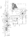
- Figure 1 is a general plan view showing the device for automatically changing cops for a weaving machine according to the present invention;
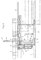
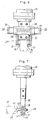
- Figure 2 is a front view as seen from the arrow lines II-II of Figure 1;
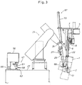
- Figure 3 is a side view of an essential part of the device as seen from the arrow lines III-III of Figure 1;
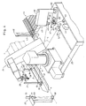
- Figure 4 is a perspective view of an essential part of the device;
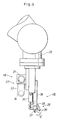
- Figure 5 is an enlarged view of an essential part of the device showing the arm portion of the robot;
- Figure 6 is an end view as seen from arrow VI of Figure 5;
- Figure 7 is an end view as seen from arrow VII of Figure 5;
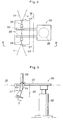
- Figure 8 is a plan view as seen from arrow VIII of Figure 3; and
- Figure 9 is a side view of an essential part as seen from line IX-IX of Figure 8.
- Figures 1 through 4 show an embodiment of the cop changing device according to the present invention which may be used for weaving the ground fabric for the press felt to be used for making paper. A sheet of ground fabric is woven on the left hand side of the arrangement illustrated in Figures 1 and 2, and a pair of shuttle boxes are placed on either side of this arrangement although only the
shuttle box 1 on the right hand side is illustrated. Ashuttle 2 is shot from theshuttle box 1 by a hammer unit not shown in the drawing, and is shot back from the other shuttle box in such a manner that the ground fabric may be woven by using a reed and leasing machine while theshuttle 2 reciprocates in the direction indicated by the arrow A in the drawing between thewarps 3 to weave aweft 4 between thewarps 3. Theshuttle boxes 1 are provided with brake units for theshuttle 2. Eachshuttle box 1 may contain a plurality of shuttles carrying different kinds of weft so that they may be used interchangeably to obtain a desired property of the woven fabric. - A
fixed frame 5 consisting of a channel member is disposed along the direction of the movement of theshuttle 2, and amoveable base 8 for ashuttle positioning unit 7 is slidably supported by aslide rail 6 extending on thefixed frame 5 as illustrated in Figure 2. Themoveable base 8 can move in the direction indicated by the arrow B in Figure 2 at two different strokes as described hereinafter by means of asmall air cylinder 11 which coupled with themoveable base 8 at its free end and fixedly secured to amoveable bracket 9 supported by theslide rail 6 in the same manner as themoveable base 8 at its base end, and alarge air cylinder 12 which is coupled with themoveable bracket 9 at its free end and fixedly secured to thefixed frame 5 at its base end. Theshuttle positioning unit 7 carried by themoveable base 8 guides anarm portion 14, carrying asuction pad 13 at its free end for engaging a front end portion of theshuttle 2 by vacuum, so as to be able to move in the vertical direction indicated by the arrow C in Figure 2 by way of a pair ofguide rods 15, and is driven by anair cylinder 16 along the vertical direction in Figure 2. Thesuction pad 13 is coupled with a vacuum generator not shown in the drawings. - A
slot 17 of a middle part of theshuttle 2 receives therein awooden bobbin 21 which is detachably fitted on atongue 18 at its one end. Thetongue 18 is pivotally supported by theshuttle 2 at an end of theslot 17 so as to permit a pivotal movement of thewooden bobbin 19 into and out of theslot 17. Acop 19 consisting of thiswooden bobbin 21 around which aweft 4 is wound is retained in theslot 17 in a horizontal condition or in its retracted position as indicated by the imaginary lines in Figure 1 during the flight of theshuttle 2, and theweft 4 unwound from thecop 19 is fed out from a shuttle eye provided on one side of theshuttle 2. - When the
shuttle 2 has reciprocated a prescribed number of times and theweft 4 stored in thecop 19 has been consumed beyond a prescribed amount, theshuttle positioning unit 7 pulls out theshuttle 2, which has reached a terminal point of its reciprocating movement and has been held stationary in theshuttle box 1 by the brake unit not shown in the drawing, to the position indicated by the solid lines in Figure 2 by engaging the front end of theshuttle 2 by suction and theshuttle 2 is placed on asupport base 23 so that thecop 19 or thecurrent cop 19 may be replaced with a new one as described hereinafter. To prevent the rear end of theshuttle 2 from being lifted from this position, a securingair cylinder 22 is mounted on a part of the fixed frame not shown in the drawing. Theshuttle 2 is thus positioned adjacent to agate 1a of theshuttle box 2 situated at a terminal end of the flight path of theshuttle 2 when thecop 19 is to be replaced. - As shown in Figure 1, a
multi-link robot 24 is mounted on a common table 25 which is disposed on one side of the thus positionedshuttle 2. As illustrated in Figures 5 and 6, therobot 24 is provide, at the free end of itssingle arm 26, with a woodenbobbin gripping hand 27 which can clamp the free end of thewooden bobbin 21, aweft gripping hand 28 which can engage theweft 4, and a woodenbobbin engaging hand 29 which can engage with an opening provided at the free end of the wooden bobbin as illustrated in Figure 7. - The wooden
bobbin gripping hand 27 comprises a pair ofair cylinders 31 disposed coaxially and opposite to each other, a pair ofarm portions 33 which are each secured to thepiston 32 of the corresponding one of theair cylinders 31 and extend downward as seen in Figure 6 in parallel with each other, andpads 34 attached to the opposing surfaces of the free ends of thearm portions 33. Areturn coil spring 35 is interposed between the twopistons 34 to elastically urge thearm portions 33 away from each other to the positions for non-active state as indicated by the solid lines in Figure 6. In active state, the twoarm portions 33 are driven in the direction indicated by the arrow D in Figure 6, and can clamp the free end of thewooden bobbin 21 with theirpads 34 as indicated by the imaginary lines in Figure 6. - The
weft gripping hand 28 comprises a fixedpawl 37 formed at the free end of afixed hand 36 and amoveable hand 38 having amoveable pawl 39. Themoveable hand 38 is rotatably supported by apivot shaft 40 extending across a slot formed in thefixed hand 36, and themoveable pawl 39 can be closed and opened by anair cylinder 30 in the direction indicated by the arrow E. The woodenbobbin engaging hand 29 is provided with aspherical head 41 integrally formed at one end of thepivot shaft 40 fixedly secured to thefixed hand 36, and can engage with an opening provided at the free end of thewooden bobbin 21 as illustrated in Figure 7. - An
ejection chute 42 is provided in an upper right corner of the common table 25 as seen in Figure 1 to remove usedcops 19, and acop storage unit 44 is provided to the right of the common table 25 to storenew cops 43 which are going to be used. Each of thenew cops 43 comprises a newwooden bobbin 46 around which anew weft 45 that is to be connected to theold weft 4 is wound, and is stored in an appropriate part of thecop storage unit 44. - At the lower right corner of the common table 25, as seen in Figure 1, is disposed a
weft tying unit 47 for connecting theold weft 4 with anew weft 45. Adjacent to thisweft tying unit 47 are disposed ahook 48 for guiding theweft 4 taken out from thecop 19 mounted on theshuttle 2 to theweft tying unit 47, and anotherhook 49 for similarly guiding thenew weft 45 taken out from thenew cop 43 stored in thecop storage unit 44. The common table 25 also carries aguide rod 51 for guiding theweft 4 taken out from theshuttle 2 to theweft tying unit 47 from a side opposite to thehooks point varying unit 52 including amoveable guide rod 50 which can move along the direction indicated by the arrow F in Figure 1 in either direction to change its position relative to theguide rod 51 so that the point of tying theold weft 4 and thenew weft 45 may be shifted relative to each other, aclamp unit 53 for supporting the free end of thenew weft 45, and a trimmedweft recovery unit 54 for recovering an extraneous part of thenew weft 45 which has been tied to theweft 4. - The aforementioned
weft tying unit 47 consists of an ultrasonic orhigh frequency welder 56 which can move vertically by means of asupport shaft 55 securely mounted upright on the common table 25 as best shown in Figures 3 and 4, a pair of locatingpins 58 for crossing theweft 4 and thenew weft 45 at three points as best shown in Figures 8 and 9,weft trimmers 57 for severing the used-up cop from the current weft and trimming an extraneous part of the weft after it has been tied, and aremover 59 for disengaging thecurrent weft 4 and thenew weft 45 from the locating pins 58 after they are tied up together into a single weft. The main body of thewelder 56 which is supported by thesupport shaft 55 in the manner of a cantilever is provided with awelding horn 61 which can move downwards from the lower end surface of the main body and upwards thereto, and ananvil 62 for thewelder 56 is mounted on a part of the common table 25 associated with thewelding horn 61 so that the three crossing points of theweft 4 and thenew weft 45 passed across the locating pins 58 may be gripped between the weldinghorn 61 and theanvil 62 to weld the wefts together. - The
weft trimmers 57 are provided on either side of theanvil 62, and each of them is constructed as a shear having a fixedblade 63 and amoveable blade 64 so that theold cop 19 may be severed from thecurrent weft 4 or an extraneous part of theweft 45 of thenew cop 46 may be trimmed, as the case may be, by driving themoveable blade 64 in the direction indicated by the arrow G in Figure 9 by means of an air cylinder or the like which is not shown in the drawings. Theremover 59 is provided with a pair ofparallel arm portions 65 which are located below the tied points of theweft 4 and thenew weft 45 to remove the connected weft from the locating pins 58 after it has been tied up, and anair cylinder 66 fixedly secured to the common table 25 to vertically drive thearm portions 65. - According to the automatic cop changing device which has been described above, the
shuttle 2 which has been kept stationary at a prescribed location, thenew cops 43 stored in thecop storage unit 44, and the aforementioned units mounted on the common table 25 are located within the moveable range of thearm 26 of therobot 24. The aforementioned units are automatically activated according to a work flow which has been programed by a control unit such as a sequencer not shown in the drawings, and an optical sensor for detecting the amount of the weft remaining on the cop, and a limit switch for detecting breakage of theweft 4 are arranged at appropriate locations as sensors required for such automatic operation of the device. - A
slack preventing unit 67 is mounted on a fixed frame not shown in the drawings to prevent any slack in the part of theweft 4 extending between the ground fabric and theshuttle 2 when theweft 4 is taken out from theshuttle 2. Thisslack preventing unit 67 is provided with a fixedring 68, and agripper 69 which can grip theweft 4 from inside the fixedring 67 as illustrated in Figures 2 and 4. Thegripper 69 is coupled with the free end of the piston rod of anair cylinder 70 via anactuator 71 for opening and closing thegripper 69 so that it may be able to be driven vertically in either direction by theair cylinder 70. - Now the operation of the above described device is now described in the following.
- First of all, the free end of the
new weft 45 taken out from thenew cop 43 stored in thecop storage unit 44 is gripped and pulled out by theweft gripping hand 28 and is hooked upon thehook 49. Thereafter, thenew weft 45 is passed across the locating pins 58 in a zig-zag manner, and the free end of thenew weft 45 is fitted into the trimmedweft recovery unit 54 by way of theclamp unit 53, thus setting thenew weft 45 in the state illustrated in Figure 1. - While the
shuttle 2 is flying, theshuttle positioning unit 7 keeps theair cylinder 16 in its retracted state and stays in its waiting condition with thesmall air cylinder 11 in its extended state and thelarge air cylinder 12 in its retracted state, as indicated by the arrow X in Figure 2. - After the
shuttle 2 has reciprocated a prescribed number of times, theshuttle 2 is held stationary in theshuttle box 1, and, by extending theair cylinder 16 while thesmall air cylinder 11 is kept in its extended state and thelarge air cylinder 12 kept in its retracted state, thearm portion 14 is brought into alignment with thegate 1a of theshuttle box 1. Then, thesmall air cylinder 11 is retracted to engage thesuction pad 13 with the free end portion of theshuttle 2 as indicated by the arrow Y in Figure 2, and theshuttle 2 is pulled out to the position indicated by the solid lines in the drawing by engaging the front end portion of theshuttle 2 by thesuction pad 13 by suction and extending both theair cylinders air cylinder 22 is lowered from its waiting position indicated by the imaginary lines in Figure 2 onto the upper surface of theshuttle 2 to locate and fix theshuttle 2 against thesupport base 23. Theslack removal unit 67 is then activated and thegripper 69 is pulled up to the positioning indicated by the arrow Z to remove slack in the part of theweft 4 extending between theshuttle 2 and the ground fabric. - Then, the
arm 26 of therobot 24 is activated so as to raise up thewooden bobbin 21 by engaging the opening at the free end of thewooden bobbin 21 lying in theshuttle 2 with the woodenbobbin engaging hand 29, and so as to pull out the part of theweft 4 adjacent to thecop 19 by gripping and pulling it with theweft gripping hand 28. Theweft 4 which has been pulled out from thecop 19 is hooked around the fixedguide rod 51 and themoveable guide rod 50 of the tyingpoint changing unit 52, passed across the locating pins 58, and then hooked around thehook 48 to thereby set up theweft 4 as illustrated in Figure 1. - Then, the
welding horn 61 is lowered to weld the three intersections of theweft 4 and thenew weft 45 which have been set up as illustrated in Figure 8 by clamping them against theanvil 62. Thereafter, theold cop 19 is severed from thecurrent weft 4 and an extraneous part of theweft 45 of thenew cop 43 is trimmed by theweft trimmers 57 to thereby complete the connection of theweft 4 with thenew weft 45 as a single continuous weft. When thewelding horn 61 is lifted up, the welded parts of theold weft 4 and thenew weft 45 are disengaged from the locating pins 58 by theremover 59. - Since the tying points of the old and new wefts would appear along a same row in the ground fabric if they were tied at regular interval, the present device changes the position of the
moveable guide rods 50 relative to the fixedguide rod 51 appropriately in order to disperse the knots produced by these tying points over the entire ground fabric. - Upon completion of the process of tying the wefts together, the
wooden bobbin 21 is pulled out from thetongue 18 of theshuttle 2 by gripping thewooden bobbin 21 with the woodenbobbin gripping hand 28 of therobot 24, and is removed out into theejection chute 42. The woodenbobbin gripping hand 28 then grips a newwooden bobbin 46 stored in the woodenbobbin storage unit 44 which is to be used next, and carries it to theshuttle 2 where thewooden bobbin 46 is fitted onto thetongue 18 and is laid inside theslot 17 into the same state as that of thewooden bobbin 21 indicated by the imaginary lines in Figure 1 to place it ready for the next weaving process. Then, the securingair cylinder 22 is brought into its retracted state. While the cop is being replaced, the trimmed part of thenew weft 45 is recovered by the trimmedweft recovery unit 54. - After the
shuttle 2 carrying the newwooden bobbin 46 is restored into theshuttle box 1 by retracting the twoair cylinders cylinders shuttle positioning unit 7 to its waiting position indicated by the arrow X in Figure 2. According to the present embodiment, immediately before shooting theshuttle 2 from theshuttle box 1 to start the process of weaving, thegripper 69 of theslack removing unit 67 is lifted to its upper most position to remove slack from the weft, and the grip of thegripper 69 on the weft is released at the same time as the shooting of theshuttle 2. Therefore, slacking of the weft resulting from the replacement of the cop can be automatically removed when resuming the process of weaving. Thus, severe impulsive tensioning of theweft 4, hence the possibility of breaking the weft can be avoided. - According to the present embodiment, the device of the present invention is provided only in one of the shuttle boxes, and, in case of a failure of the device, replacement of the cops can be carried out manually in conventional manner on the other shuttle box which is provided with a sufficient space for that. Alternatively, a pair of such devices may be disposed on either side, and, in this case, the cops may be replaced on either side to more efficiently utilize the weft.
- Thus, according to the present invention, since a series of steps related to the processes of positioning the shuttle, tying the wefts, and replacing the cops can be carried out automatically without involving any manual process, replacement of cops for weaving can be carried out automatically and the cost of the weaving process can be reduced to a significant extent. Also, since the various actions can be effected with a single robot arm, the cop changing device may be simplified and made highly compact.
Claims (16)
- An automatic cop changing device for a weaving machine in which a shuttle (2) carrying a cop (19) consisting of a bobbin (21) around which a (4) weft is wound is reciprocated between warps (3) so as to weave said weft between said warps, comprising:cop positioning means (7) for keeping said shuttle stationary
near a terminal point of its reciprocating movement when the weft of a current cop mounted on said shuttle is consumed by more than a prescribed amount;cop storage means (44) for storing a plurality of new cops; weft pulling means (28) for drawing the weft from said current cop and a weft from one of said new cops stored in said cop storage means, and crossing said two wefts;weft tying means (47) for tying said crossed part of said wefts;weft trimming means (57) for trimming an extraneous part of said tied weft; andcop replacing means (27) for removing said current cop from said shuttle, and mounting said new cop on said shuttle;said cop replacing means consisting of a single robot arm (26) comprising a base rotatable around a vertical axis, an arm assembly movable both radially and vertically with respect to said base, and a hand assembly carried by a free end of said arm assembly to manipulate said shuttles. - An automatic cop changing device according to claim 1 wherein said tying means consists of a welding unit (56).
- An automatic cop changing device according to claim 1, further comprising slack removing means (67) for taking up slack from said tied weft after said new cop is mounted on said shuttle and before said shuttle is shot from said terminal point of its reciprocating movement to another terminal point.
- An automatic cop changing device according to claim 3, wherein said slack removing means comprising a stationary ring (68) placed adjacent to a part of said weft from said new cop, a gripper (69) which can selectively grip said weft from inside said stationary ring and release it as required, and gripper driving means (70) for selectively moving said gripper away from and towards said stationary ring.
- An automatic cop changing device according to claim 1, wherein said weft pulling means comprises a table (62), a weft gripping hand (36) carried by a robot which can grip an end of said weft of said new cop stored in said cop storage means and a part of said weft extending from said current cop, a pair of locating pins (58) projecting upright from said table to cross said wefts at three points by passing said wefts along different sides of said locating pins in a criss-cross manner with said weft gripping hand, disengaging arms (65) placed under said wefts from said locating pins by pushing off said weft from said locating pins.
- An automatic cop changing device according to claim 5, wherein said weft pulling means comprises tied point varying means (52) for changing the point of tying by said weft tying means by changing the length of a span of said weft between said point of tying of said weft and said current cop.
- An automatic cop changing device according to claim 6, wherein said tied point varying means comprises a stationary rod (51) projecting upright from said table, a moveable rod (50) projecting upright from said table so as to be able to move toward and away from said stationary rod to change said point of tying relative to said cop at said terminal point, and means of retracting said rods into said table to disengage said weft therefrom.
- An automatic cop changing device according to claim 6, wherein said hand assembly further comprises said weft gripping hand (36).
- An automatic cop changing device according to claim 8, wherein said weft gripping hand comprises a pair of pawls (37, 39) which are pivotally connected to each other by a pivot shaft (40) so as to grip a weft between said pawls, and said spherical head (41) of said cop raising hand is formed at an end of said pivot shaft.
- An automatic cop changing device according to claim 1, wherein said hand assembly comprises a cop raising hand (28) for moving a cop between a retracted position is said shuttle and an upright position is said shuttle, and a cop gripping hand (29) for gripping a cop and carrying it between its upright position in said shuttle and a storage position in said cop storage means.
- An automatic cop changing device according to claim 10, wherein said cop is pivotally and detachably supported at its base end by said shuttle so as to be pivotable between its upright position and its retracted position, and said cop raising hand comprises a spherical head (41) which is adapted to engage a free end of said cop and move it between its upright position and its retracted position.
- An automatic cop changing device according to claims 1 to 24 additionally comprising slack removing means (67) for taking up slack from said tied weft after said new cop is mounted on said shuttle and before said shuttle is shot from terminal point of its reciprocating movement to another terminal point.
- An automatic cop changing device according to claim 12, wherein said slack removing means comprises a stationary ring (68) placed adjacent to a part of said weft from said new cop, a gripper which can selectively grip said weft from inside said stationary ring and release it as required, and a gripper driving means (170) for selectively moving said gripper away from and towards said stationary ring.
- An automatic cop changing device according to claim 13, wherein said weft pulling means comprises tied point varying means (52) for changing the point of tying by said weft tying means by changing the length of span of said weft between said point of tying of said weft and said current cop.
- An automatic cop changing device according to claim 12, wherein said tied point varying means comprises a stationary rod (51) projecting upright from a table (25), a moveable rod (50) projecting upright from said table so as to be able to move toward and away from said stationary rod to change said point of tying relative to said cop at its terminal point, and means of retracting said rods into said table to disengage said weft therefrom.
- An automatic cop changing device according to any of claims 1 to 15 in which said hand assembly carried by a free end of said arm assembly draws a weft from said current cop and a weft from one of said new cops stored in said cop storage means and additionally comprises weft securing means (48,49,53) for temporarily securing said two wefts drawn by said hand assembly in a crossed state.
Applications Claiming Priority (8)
| Application Number | Priority Date | Filing Date | Title |
|---|---|---|---|
| JP30959888 | 1988-12-07 | ||
| JP63309598A JPH0726279B2 (en) | 1988-12-07 | 1988-12-07 | Automatic cup changer for loom |
| JP309598/88 | 1988-12-07 | ||
| JP30959988 | 1988-12-07 | ||
| JP309599/88 | 1988-12-07 | ||
| JP30959988A JPH0665774B2 (en) | 1988-12-07 | 1988-12-07 | Automatic cup changer for loom |
| EP89312561A EP0372856B1 (en) | 1988-12-07 | 1989-12-01 | Automatic cop changing device for a weaving machine |
| EP94201080A EP0613969B1 (en) | 1988-12-07 | 1989-12-01 | Automatic cop changing device for a weaving machine |
Related Parent Applications (2)
| Application Number | Title | Priority Date | Filing Date |
|---|---|---|---|
| EP94201080.2 Division | 1989-12-01 | ||
| EP94201080A Division EP0613969B1 (en) | 1988-12-07 | 1989-12-01 | Automatic cop changing device for a weaving machine |
Publications (3)
| Publication Number | Publication Date |
|---|---|
| EP0741199A2 true EP0741199A2 (en) | 1996-11-06 |
| EP0741199A3 EP0741199A3 (en) | 1997-03-05 |
| EP0741199B1 EP0741199B1 (en) | 2000-06-28 |
Family
ID=26566013
Family Applications (4)
| Application Number | Title | Priority Date | Filing Date |
|---|---|---|---|
| EP94201080A Expired - Lifetime EP0613969B1 (en) | 1988-12-07 | 1989-12-01 | Automatic cop changing device for a weaving machine |
| EP89312561A Expired - Lifetime EP0372856B1 (en) | 1988-12-07 | 1989-12-01 | Automatic cop changing device for a weaving machine |
| EP96109170A Expired - Lifetime EP0741199B1 (en) | 1988-12-07 | 1989-12-01 | Automatic cop changing device for a weaving machine |
| EP96109171A Expired - Lifetime EP0738795B1 (en) | 1988-12-07 | 1989-12-01 | Automatic cop changing device for a weaving machine |
Family Applications Before (2)
| Application Number | Title | Priority Date | Filing Date |
|---|---|---|---|
| EP94201080A Expired - Lifetime EP0613969B1 (en) | 1988-12-07 | 1989-12-01 | Automatic cop changing device for a weaving machine |
| EP89312561A Expired - Lifetime EP0372856B1 (en) | 1988-12-07 | 1989-12-01 | Automatic cop changing device for a weaving machine |
Family Applications After (1)
| Application Number | Title | Priority Date | Filing Date |
|---|---|---|---|
| EP96109171A Expired - Lifetime EP0738795B1 (en) | 1988-12-07 | 1989-12-01 | Automatic cop changing device for a weaving machine |
Country Status (7)
| Country | Link |
|---|---|
| US (1) | US5016677A (en) |
| EP (4) | EP0613969B1 (en) |
| AT (2) | ATE151822T1 (en) |
| CA (1) | CA2004655C (en) |
| DE (4) | DE68927981T2 (en) |
| ES (4) | ES2150049T3 (en) |
| FI (1) | FI91000C (en) |
Families Citing this family (6)
| Publication number | Priority date | Publication date | Assignee | Title |
|---|---|---|---|---|
| JPH07145535A (en) * | 1993-11-17 | 1995-06-06 | Nippon Felt Co Ltd | Cop changing device for weaving machine |
| SE508919C2 (en) * | 1994-01-26 | 1998-11-16 | Texo Ab | Method of producing and using coil in shuttle and shuttle coil with wire holding device |
| SE508213C2 (en) * | 1994-04-27 | 1998-09-14 | Texo Ab | Procedure for automatic bobbin changing in weaving machine and device for weaving machine for automatic bobbin changing function |
| ITMI20051470A1 (en) * | 2005-07-28 | 2007-01-29 | Mec Trinca Colonel Silvio & Figlio | EQUIPMENT FOR SHIFT CHANGE IN SHUTTLE FRAMES |
| DE102011016755B3 (en) * | 2011-04-12 | 2012-10-04 | CU4motion GmbH | Arrangement and method for mounting and / or disassembling and maintaining a needle board |
| CN109176014B (en) * | 2018-10-19 | 2020-02-07 | 华创天元实业发展有限责任公司 | Non-stop wire-changing device for steel skeleton plastic composite pipe production equipment |
Citations (4)
| Publication number | Priority date | Publication date | Assignee | Title |
|---|---|---|---|---|
| GB936286A (en) * | 1960-11-15 | 1963-09-11 | Rueti Ag Maschf | Improvements in or relating to looms |
| US3608589A (en) * | 1969-06-09 | 1971-09-28 | Associated Perforators & Weave | Automatic pirn changer for a loom |
| US4486928A (en) * | 1981-07-09 | 1984-12-11 | Magnavox Government And Industrial Electronics Company | Apparatus for tool storage and selection |
| EP0295700A2 (en) * | 1987-06-16 | 1988-12-21 | Ichikawa Co.,Ltd. | Automatic cop exchanging apparatus for shuttle loom |
Family Cites Families (6)
| Publication number | Priority date | Publication date | Assignee | Title |
|---|---|---|---|---|
| US2872948A (en) * | 1956-08-31 | 1959-02-10 | Draper Corp | Automatic bobbin replenishing loom |
| AT225638B (en) * | 1960-02-26 | 1963-01-25 | Valentin Patent Ges G M B H | Weft bobbin feeding device for looms with automatic weft bobbin changing device |
| CH396797A (en) * | 1962-03-16 | 1965-07-31 | Rueti Ag Maschf | Device for bringing the weft bobbin to the automatic bobbin changing machine of a mechanical loom |
| US3175588A (en) * | 1963-03-15 | 1965-03-30 | Burlington Industries Inc | Filling tail removal equipment |
| CH609013A5 (en) * | 1975-12-18 | 1979-02-15 | Schweiter Ag Maschf | |
| US4106973A (en) * | 1977-01-17 | 1978-08-15 | Narricot Industries, Inc. | Yarn welding device |
-
1989
- 1989-11-27 FI FI895666A patent/FI91000C/en not_active IP Right Cessation
- 1989-11-29 US US07/443,609 patent/US5016677A/en not_active Expired - Lifetime
- 1989-12-01 DE DE68927981T patent/DE68927981T2/en not_active Expired - Fee Related
- 1989-12-01 EP EP94201080A patent/EP0613969B1/en not_active Expired - Lifetime
- 1989-12-01 ES ES96109170T patent/ES2150049T3/en not_active Expired - Lifetime
- 1989-12-01 DE DE68921307T patent/DE68921307T2/en not_active Expired - Fee Related
- 1989-12-01 ES ES89312561T patent/ES2070184T3/en not_active Expired - Lifetime
- 1989-12-01 DE DE68929200T patent/DE68929200T2/en not_active Expired - Fee Related
- 1989-12-01 EP EP89312561A patent/EP0372856B1/en not_active Expired - Lifetime
- 1989-12-01 AT AT94201080T patent/ATE151822T1/en not_active IP Right Cessation
- 1989-12-01 DE DE68929226T patent/DE68929226T2/en not_active Expired - Fee Related
- 1989-12-01 EP EP96109170A patent/EP0741199B1/en not_active Expired - Lifetime
- 1989-12-01 ES ES94201080T patent/ES2100017T3/en not_active Expired - Lifetime
- 1989-12-01 AT AT89312561T patent/ATE118828T1/en not_active IP Right Cessation
- 1989-12-01 ES ES96109171T patent/ES2145342T3/en not_active Expired - Lifetime
- 1989-12-01 EP EP96109171A patent/EP0738795B1/en not_active Expired - Lifetime
- 1989-12-05 CA CA002004655A patent/CA2004655C/en not_active Expired - Fee Related
Patent Citations (4)
| Publication number | Priority date | Publication date | Assignee | Title |
|---|---|---|---|---|
| GB936286A (en) * | 1960-11-15 | 1963-09-11 | Rueti Ag Maschf | Improvements in or relating to looms |
| US3608589A (en) * | 1969-06-09 | 1971-09-28 | Associated Perforators & Weave | Automatic pirn changer for a loom |
| US4486928A (en) * | 1981-07-09 | 1984-12-11 | Magnavox Government And Industrial Electronics Company | Apparatus for tool storage and selection |
| EP0295700A2 (en) * | 1987-06-16 | 1988-12-21 | Ichikawa Co.,Ltd. | Automatic cop exchanging apparatus for shuttle loom |
Also Published As
| Publication number | Publication date |
|---|---|
| EP0741199B1 (en) | 2000-06-28 |
| EP0738795A3 (en) | 1997-03-05 |
| EP0738795A2 (en) | 1996-10-23 |
| DE68929200T2 (en) | 2000-11-09 |
| DE68921307T2 (en) | 1995-08-10 |
| ES2150049T3 (en) | 2000-11-16 |
| FI91000C (en) | 1994-04-25 |
| ES2145342T3 (en) | 2000-07-01 |
| DE68929226D1 (en) | 2000-08-03 |
| CA2004655C (en) | 1994-05-03 |
| DE68929226T2 (en) | 2001-03-08 |
| ATE118828T1 (en) | 1995-03-15 |
| EP0372856B1 (en) | 1995-02-22 |
| DE68929200D1 (en) | 2000-05-31 |
| FI91000B (en) | 1994-01-14 |
| EP0613969B1 (en) | 1997-04-16 |
| EP0613969A2 (en) | 1994-09-07 |
| DE68921307D1 (en) | 1995-03-30 |
| CA2004655A1 (en) | 1990-06-07 |
| ATE151822T1 (en) | 1997-05-15 |
| EP0372856A1 (en) | 1990-06-13 |
| EP0613969A3 (en) | 1994-12-21 |
| ES2100017T3 (en) | 1997-06-01 |
| ES2070184T3 (en) | 1995-06-01 |
| DE68927981D1 (en) | 1997-05-22 |
| EP0738795B1 (en) | 2000-04-26 |
| FI895666A0 (en) | 1989-11-27 |
| EP0741199A3 (en) | 1997-03-05 |
| US5016677A (en) | 1991-05-21 |
| DE68927981T2 (en) | 1997-08-21 |
Similar Documents
| Publication | Publication Date | Title |
|---|---|---|
| US4581794A (en) | Automatic seaming machine for fabric belts | |
| EP0236601B1 (en) | Automatic seaming machine for fabric belts | |
| EP0741199B1 (en) | Automatic cop changing device for a weaving machine | |
| JP2948001B2 (en) | Automatic cup changer for looms | |
| JP2603444B2 (en) | Yarning device of the cup changing device for looms | |
| JP2948003B2 (en) | Cup changing device for loom | |
| JPH02154031A (en) | Automatic cop exchanger for loom | |
| FI91001C (en) | Automatic weave spool changer for the weaving machine | |
| JP3249624B2 (en) | Control method for cup changing device for loom | |
| JPH0726279B2 (en) | Automatic cup changer for loom | |
| JP2948002B2 (en) | Cup recovery device for looms | |
| EP0656436B1 (en) | Automated cop changing device for a weaving machine | |
| JPH11512152A (en) | Loom | |
| CA1318830C (en) | Method of manufacturing an insertion-type seam for making a cloth belt endless, and seaming machine | |
| JPH0515838B2 (en) | ||
| JP2810882B2 (en) | Continuous yarn splitting device | |
| JPH0827644A (en) | Cop exchanger for weaving machine | |
| JPH1025655A (en) | Needle thread exchange device of sewing machine | |
| US5249606A (en) | Isolating a yarn end of a broken warp thread from the warp in a weaving machine | |
| JPH0827645A (en) | Wood bobbin exchanger for shuttle | |
| JPH07157946A (en) | Cop changing device for weaving machine | |
| JPH07145536A (en) | Cop changing device for weaving machine | |
| NZ214916A (en) | Machine for making woven seam in fabric belt e.g. fourdrinier belt | |
| JPH01111030A (en) | Strip fiber splicing method and apparatus |
Legal Events
| Date | Code | Title | Description |
|---|---|---|---|
| PUAI | Public reference made under article 153(3) epc to a published international application that has entered the european phase |
Free format text: ORIGINAL CODE: 0009012 |
|
| 17P | Request for examination filed |
Effective date: 19960626 |
|
| AC | Divisional application: reference to earlier application |
Ref document number: 613969 Country of ref document: EP |
|
| AK | Designated contracting states |
Kind code of ref document: A2 Designated state(s): DE ES GB IT SE |
|
| RIN1 | Information on inventor provided before grant (corrected) |
Inventor name: IWASAKI, TOKUJI Inventor name: KONNO, TETSUYA, CHIYODA KAKOU KENSETSU K.K. Inventor name: AOYAGI, TAKAYOSHI Inventor name: OKAZAKI, SADAAKI Inventor name: MURAKAMI, FUMIO |
|
| PUAL | Search report despatched |
Free format text: ORIGINAL CODE: 0009013 |
|
| AK | Designated contracting states |
Kind code of ref document: A3 Designated state(s): DE ES GB IT SE |
|
| 17Q | First examination report despatched |
Effective date: 19980825 |
|
| GRAG | Despatch of communication of intention to grant |
Free format text: ORIGINAL CODE: EPIDOS AGRA |
|
| GRAG | Despatch of communication of intention to grant |
Free format text: ORIGINAL CODE: EPIDOS AGRA |
|
| GRAH | Despatch of communication of intention to grant a patent |
Free format text: ORIGINAL CODE: EPIDOS IGRA |
|
| GRAH | Despatch of communication of intention to grant a patent |
Free format text: ORIGINAL CODE: EPIDOS IGRA |
|
| GRAA | (expected) grant |
Free format text: ORIGINAL CODE: 0009210 |
|
| AC | Divisional application: reference to earlier application |
Ref document number: 613969 Country of ref document: EP Ref document number: 372856 Country of ref document: EP |
|
| AK | Designated contracting states |
Kind code of ref document: B1 Designated state(s): DE ES GB IT SE |
|
| ITF | It: translation for a ep patent filed |
Owner name: JACOBACCI & PERANI S.P.A. |
|
| REF | Corresponds to: |
Ref document number: 68929226 Country of ref document: DE Date of ref document: 20000803 |
|
| REG | Reference to a national code |
Ref country code: ES Ref legal event code: FG2A Ref document number: 2150049 Country of ref document: ES Kind code of ref document: T3 |
|
| EN | Fr: translation not filed | ||
| PLBE | No opposition filed within time limit |
Free format text: ORIGINAL CODE: 0009261 |
|
| STAA | Information on the status of an ep patent application or granted ep patent |
Free format text: STATUS: NO OPPOSITION FILED WITHIN TIME LIMIT |
|
| 26N | No opposition filed | ||
| REG | Reference to a national code |
Ref country code: GB Ref legal event code: IF02 |
|
| PGFP | Annual fee paid to national office [announced via postgrant information from national office to epo] |
Ref country code: DE Payment date: 20051212 Year of fee payment: 17 |
|
| PGFP | Annual fee paid to national office [announced via postgrant information from national office to epo] |
Ref country code: SE Payment date: 20051214 Year of fee payment: 17 |
|
| PGFP | Annual fee paid to national office [announced via postgrant information from national office to epo] |
Ref country code: ES Payment date: 20051215 Year of fee payment: 17 |
|
| PGFP | Annual fee paid to national office [announced via postgrant information from national office to epo] |
Ref country code: GB Payment date: 20051222 Year of fee payment: 17 |
|
| PG25 | Lapsed in a contracting state [announced via postgrant information from national office to epo] |
Ref country code: SE Free format text: LAPSE BECAUSE OF NON-PAYMENT OF DUE FEES Effective date: 20061202 |
|
| PGFP | Annual fee paid to national office [announced via postgrant information from national office to epo] |
Ref country code: IT Payment date: 20061231 Year of fee payment: 18 |
|
| PG25 | Lapsed in a contracting state [announced via postgrant information from national office to epo] |
Ref country code: DE Free format text: LAPSE BECAUSE OF NON-PAYMENT OF DUE FEES Effective date: 20070703 |
|
| EUG | Se: european patent has lapsed | ||
| GBPC | Gb: european patent ceased through non-payment of renewal fee |
Effective date: 20061201 |
|
| PG25 | Lapsed in a contracting state [announced via postgrant information from national office to epo] |
Ref country code: GB Free format text: LAPSE BECAUSE OF NON-PAYMENT OF DUE FEES Effective date: 20061201 |
|
| REG | Reference to a national code |
Ref country code: ES Ref legal event code: FD2A Effective date: 20061202 |
|
| PG25 | Lapsed in a contracting state [announced via postgrant information from national office to epo] |
Ref country code: ES Free format text: LAPSE BECAUSE OF NON-PAYMENT OF DUE FEES Effective date: 20061202 |
|
| PG25 | Lapsed in a contracting state [announced via postgrant information from national office to epo] |
Ref country code: IT Free format text: LAPSE BECAUSE OF NON-PAYMENT OF DUE FEES Effective date: 20071201 |