EP0742029A1 - Interventional catheter - Google Patents
Interventional catheter Download PDFInfo
- Publication number
- EP0742029A1 EP0742029A1 EP95106808A EP95106808A EP0742029A1 EP 0742029 A1 EP0742029 A1 EP 0742029A1 EP 95106808 A EP95106808 A EP 95106808A EP 95106808 A EP95106808 A EP 95106808A EP 0742029 A1 EP0742029 A1 EP 0742029A1
- Authority
- EP
- European Patent Office
- Prior art keywords
- catheter tube
- balloon
- piece
- distal
- catheter
- Prior art date
- Legal status (The legal status is an assumption and is not a legal conclusion. Google has not performed a legal analysis and makes no representation as to the accuracy of the status listed.)
- Withdrawn
Links
Images

Classifications
-
- A—HUMAN NECESSITIES
- A61—MEDICAL OR VETERINARY SCIENCE; HYGIENE
- A61M—DEVICES FOR INTRODUCING MEDIA INTO, OR ONTO, THE BODY; DEVICES FOR TRANSDUCING BODY MEDIA OR FOR TAKING MEDIA FROM THE BODY; DEVICES FOR PRODUCING OR ENDING SLEEP OR STUPOR
- A61M25/00—Catheters; Hollow probes
- A61M25/0067—Catheters; Hollow probes characterised by the distal end, e.g. tips
- A61M25/0068—Static characteristics of the catheter tip, e.g. shape, atraumatic tip, curved tip or tip structure
- A61M25/0069—Tip not integral with tube
-
- A—HUMAN NECESSITIES
- A61—MEDICAL OR VETERINARY SCIENCE; HYGIENE
- A61M—DEVICES FOR INTRODUCING MEDIA INTO, OR ONTO, THE BODY; DEVICES FOR TRANSDUCING BODY MEDIA OR FOR TAKING MEDIA FROM THE BODY; DEVICES FOR PRODUCING OR ENDING SLEEP OR STUPOR
- A61M25/00—Catheters; Hollow probes
- A61M25/0043—Catheters; Hollow probes characterised by structural features
-
- A—HUMAN NECESSITIES
- A61—MEDICAL OR VETERINARY SCIENCE; HYGIENE
- A61M—DEVICES FOR INTRODUCING MEDIA INTO, OR ONTO, THE BODY; DEVICES FOR TRANSDUCING BODY MEDIA OR FOR TAKING MEDIA FROM THE BODY; DEVICES FOR PRODUCING OR ENDING SLEEP OR STUPOR
- A61M25/00—Catheters; Hollow probes
- A61M25/0067—Catheters; Hollow probes characterised by the distal end, e.g. tips
-
- A—HUMAN NECESSITIES
- A61—MEDICAL OR VETERINARY SCIENCE; HYGIENE
- A61M—DEVICES FOR INTRODUCING MEDIA INTO, OR ONTO, THE BODY; DEVICES FOR TRANSDUCING BODY MEDIA OR FOR TAKING MEDIA FROM THE BODY; DEVICES FOR PRODUCING OR ENDING SLEEP OR STUPOR
- A61M25/00—Catheters; Hollow probes
- A61M25/10—Balloon catheters
- A61M25/1025—Connections between catheter tubes and inflation tubes
-
- A—HUMAN NECESSITIES
- A61—MEDICAL OR VETERINARY SCIENCE; HYGIENE
- A61M—DEVICES FOR INTRODUCING MEDIA INTO, OR ONTO, THE BODY; DEVICES FOR TRANSDUCING BODY MEDIA OR FOR TAKING MEDIA FROM THE BODY; DEVICES FOR PRODUCING OR ENDING SLEEP OR STUPOR
- A61M25/00—Catheters; Hollow probes
- A61M25/0043—Catheters; Hollow probes characterised by structural features
- A61M25/0045—Catheters; Hollow probes characterised by structural features multi-layered, e.g. coated
- A61M2025/0046—Coatings for improving slidability
- A61M2025/0047—Coatings for improving slidability the inner layer having a higher lubricity
-
- A—HUMAN NECESSITIES
- A61—MEDICAL OR VETERINARY SCIENCE; HYGIENE
- A61M—DEVICES FOR INTRODUCING MEDIA INTO, OR ONTO, THE BODY; DEVICES FOR TRANSDUCING BODY MEDIA OR FOR TAKING MEDIA FROM THE BODY; DEVICES FOR PRODUCING OR ENDING SLEEP OR STUPOR
- A61M25/00—Catheters; Hollow probes
- A61M25/10—Balloon catheters
- A61M2025/1043—Balloon catheters with special features or adapted for special applications
- A61M2025/1093—Balloon catheters with special features or adapted for special applications having particular tip characteristics
-
- A—HUMAN NECESSITIES
- A61—MEDICAL OR VETERINARY SCIENCE; HYGIENE
- A61M—DEVICES FOR INTRODUCING MEDIA INTO, OR ONTO, THE BODY; DEVICES FOR TRANSDUCING BODY MEDIA OR FOR TAKING MEDIA FROM THE BODY; DEVICES FOR PRODUCING OR ENDING SLEEP OR STUPOR
- A61M25/00—Catheters; Hollow probes
- A61M25/0043—Catheters; Hollow probes characterised by structural features
- A61M25/0045—Catheters; Hollow probes characterised by structural features multi-layered, e.g. coated
-
- A—HUMAN NECESSITIES
- A61—MEDICAL OR VETERINARY SCIENCE; HYGIENE
- A61M—DEVICES FOR INTRODUCING MEDIA INTO, OR ONTO, THE BODY; DEVICES FOR TRANSDUCING BODY MEDIA OR FOR TAKING MEDIA FROM THE BODY; DEVICES FOR PRODUCING OR ENDING SLEEP OR STUPOR
- A61M25/00—Catheters; Hollow probes
- A61M25/10—Balloon catheters
- A61M25/104—Balloon catheters used for angioplasty
Definitions
- This invention relates to an interventional catheter comprising a catheter tube having proximal and distal ends, an inner layer of material forming a longitudinal lumen in the catheter tube for the sliding fit of a guide wire, an outer layer of material superposed to said inner layer and forming an outer surface of the catheter tube, said inner and outer layers of materials being secured in relation to one another and having mechanical properties differing from one another, a balloon with proximal and distal necks whereby the distal neck of the balloon sealingly surrounds the catheter tube, and a tip at the distal end of the catheter tube.
- the guide wire catheters are now widely used for interventions such as percutaneous transluminal angioplasty.
- a problem with these catheters is that the guide wire may clog into the longitudinal lumen of the catheter; as a result, the guide wire may follow the balloon upon withdrawal thereof after the inflation procedure, thereby making it necessary to re-insert the guide wire into the treated area of the blood vessel for re-positioning a balloon in case a second inflation is needed.
- the catheter also has to achieve an acceptable compromise between the requirements of some stiffness to assure good pushability and of some flexibility to assure kink resistance. And of course it has to permit safe attachment of the balloon to the catheter tube.
- European Patent Application N° 93117403.1 filed October 27, 1993 by the Applicant shows a catheter comprising a catheter tube having two superposed layers of materials secured in relation to one another and with mechanical properties differing from one another, a longitudinal lumen in the catheter tube for the sliding fit of a guide wire, and a balloon with a proximal end and a distal end sealingly surrounding the catheter tube, whereby the catheter tube has an inner layer forming the longitudinal lumen and an outer layer forming the outer surface of the catheter tube.
- the inner layer is formed of a material with lower friction coefficient than the material forming the outer layer, whereby there is no more risk of having the guide wire clogging in the longitudinal lumen of the catheter tube.
- the document WO 92/11893 describes an intra aortic balloon apparatus comprising a hollow catheter in which is located an elongated member forming a central lumen extending out of the catheter at the distal end thereof.
- An aortic pumping balloon is positioned over the elongated member and the distal end of the balloon is bonded to a tip engaged over the distal end of the elongated member.
- the elongated member is formed of an inner layer comprised of a soft elastomeric material and the outer layer is comprised of a hard plastic material. This balloon apparatus cannot be loaded with a guide wire and moved into tortuous vessels with the guide wire loaded inside the elongated tube.
- this balloon apparatus cannot be introduced into narrow vessels or stenoses nor can it be passed through narrow punctures to enter the blood vessels because of the large profile of the folded balloon resulting from the fact that the balloon is bonded to an intermediate tip which in turn is mounted over and bonded to the elongated element.
- the purpose of this invention is to present an interventional, low profile, highly resistant balloon catheter with improved moveability into tortuous vessels and an added capacity of reducing the risk of injury.
- interventional catheter according to the invention complies with the definitions given in the claims.
- the tip is a piece of material having proximal and distal portions whereby said proximal portion is in longitudinal extension of the outer layer, with the inner layer ending proximally of the said proximal portion and the piece of material having an inner wall in longitudinal alignment with the longitudinal lumen
- the tip allows a low profile with selective flexibility at the distal end of the catheter tube; this results in a better trackability through narrow or tortuous vessels, as well as in a strong reduction of the risk of injury.
- the catheter thus conforms easily with the vessel configurations, more particularly along low radius curves, and the resulting low friction substantially reduces the risk of injury to the vessel in these delicate areas.
- the catheter end may have a strong diameter reduction which cannot be achieved by a simple multilayer catheter end because of the hazardous loss of resistance of the superposed layers.
- the distal end of the catheter has an added stepped flexibility which enhances the catheter capacity to reach very narrow or tortuous vessel locations with still less risk of injury.
- the outer layer may easily have a diameter reduction which simultaneously protects the inner layer of the catheter tube.
- the distal neck of the balloon may sealingly surround a part of the proximal portion of the piece of material, sealing being for instance by welding.
- the piece of material forming the tip may also be formed by the distal neck of the balloon, in which case the maximal diameter reduction may be achieved without removal of material at that level while simultaneously retaining the advantage of protection of the ends of the superposed layer of the catheter tube.
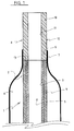
- Figure 1 is a longitudinal cut out of a first embodiment.
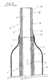
- Figure 2 is a longitudinal cut out of a second embodiment.
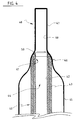
- Figure 3 is a longitudinal cut out of a third embodiment.
- Figure 4 is a longitudinal cut out of a fourth embodiment.
- the interventional catheter shown in Figure 1 comprises a catheter tube 1 having a proximal end (not shown) and a distal end 2.
- the catheter tube 1 is formed of two superposed continuous layers 3 and 4 extending all over the length of tube 1; this tubing, which may be achieved by the known coextrusion technology, i.e. by extruding the outer layer 4 over the inner layer, is comprised of a polyethylene, preferably a high density polyethylene, for the inner layer 3, and of a polyamid for the outer layer 4.
- the inner layer thus forms a longitudinal lumen 5 with a very low friction coefficient, lower than that of the material forming the outer layer 4, and a non kinking capacity.
- the outer layer 4, which forms an outer surface of the catheter tube, is easily weldable to the materials commonly used for making balloons for angioplasty purposes and the like.
- the lumen 5 is for the sliding fit of a guide wire (not shown).
- a balloon 6 Over the distal end 2 of the catheter tube 1 is positioned a balloon 6 with a distal neck 7 which is sealed to the outer layer 4 of the catheter tube 1, for instance by welding.
- the balloon 6 has a proximal neck (not shown) which is affixed to the catheter tube 1 which is also provided with an inflation lumen for the balloon 6 in a conventional manner.
- the balloon 6 is made of a polyamid.
- a tip 8 formed by a piece of material 12 having a proximal portion 9 and a distal portion 10 is arranged at the distal end 2 of the catheter tube 1.
- This tip has its proximal portion 9 in longitudinal extension of the outer layer 4 of the catheter tube 1, and the inner layer 3 of the catheter tube 1 ends proximally of the proximal portion 9 of tip 8.
- the tip 8 has an inner wall 11 in longitudinal alignment with the longitudinal lumen 5 and therefore the proximal extremity of its proximal end fully protects the distal ends of inner and outer layers 3 and 4.
- proximal end of the proximal portion 9 of tip 8 is welded to the distal end 2 of the catheter tube 1, and the distal neck 7 of the balloon 6 sealingly surrounds, for instance by welding, a part of the proximal portion 9 of tip 8.
- the tip 8 is preferably made of a polyamid, and welding of the distal neck 7 of the balloon 6 to the distal end 2 of the catheter tube 1 and to the proximal portion 9 of the tip 8 may be achieved in one single step. Welding may be effected by laser or hot air.
- the interventional catheter shown in Figure 2 comprises the same integers and arrangements as the catheter shown in Figure 1, which are identically referenced.
- the piece of material 12 forming the tip 8 tapers distally as shown by reference numeral 14.
- the diameter reduction extends slightly above the diameter of the inner layer 3, a reduction which could not be achieved on the two layer catheter tube 1 without a serious risk of damage to the outer layer 4. It may be noted that, due to the one integral configuration of the piece of material 12 forming the tip 8, an even greater diameter reduction could be achieved, substantially beneath the diameter of the outer layer, as shown in phantom at 14.
- the catheter shown in Figure 3 also comprises a catheter tube 20 having a proximal end (not shown) and a distal end 21.
- the catheter tube 20 is formed of two superposed continuous layers 22 and 23 extending all over the length of the catheter tube with the inner layer forming a longitudinal lumen 24; this tubing may also be achieved by the coextrusion technology, the outer layer 23 being extruded over the inner layer 22.
- the inner layer 22 is made of a polyethylene, preferably a high density polyethylene, and the outer layer a polyamid.
- a balloon 25 Over the distal end 21 of the catheter tube 20 is arranged a balloon 25 with a distal neck 26 sealed to the outer layer 23 of the catheter tube 20.
- the balloon 25 has a proximal neck (not shown)which is affixed to the catheter tube 20 which is also provided with the conventional lumen for fluid entry into the balloon.
- the balloon 25 is also preferably made of a polyamid.
- a tip 27 comprising a piece of material 28 having a proximal portion 29 and a distal portion 30 is arranged at the distal end 21 of the catheter tube 20.
- the piece of material 28 is formed by the outer layer 23 of catheter tube 20 which is longitudinally and distally extended beyond the distal end of inner layer 22 and constricted so as to have an inner wall 31 in longitudinal alignment with the longitudinal lumen 24 of catheter tube 20, thereby having a proximal extremity 32 fully protecting the distal end of inner layer 22.
- the constriction of outer layer 23 may be obtained by the shrink tube technology, i.e., by heating the piece of material 28 to have it shrink down on a mandrel of appropriate diameter.
- the inner layer 22 is made of a polyethylene or high density polyethylene, whereas the outer layer 23 and the balloon are made of a polyamid.
- the tip 27 can also taper distally as in the embodiment of Figure 2.
- the embodiment of Figure 4 comprises a catheter tube 40 having a proximal end (not shown) and a distal end 41.
- the catheter tube 40 is formed of two superposed coextruded layers 42 and 43 extending all over the length of the catheter tube, with the inner layer forming a longitudinal lumen 44 for the sliding fit of a guide wire (not shown).
- the inner layer 42 is preferably made of a polyethylene or high density polyethylene and the outer layer a polyamid.
- a balloon 45 Over the distal end 41 of the catheter tube 40 is arranged a balloon 45, preferably made of a polyamid, having a distal neck 46 sealed to the outer layer 43.
- the distal neck 46 of the balloon 45 is further extended distally of the distal ends of inner and outer layers 42 and 43 to form a piece of material 47 constituting the tip 48.
- the extended balloon neck forming the piece of material 47, the proximal portion 50 of which is in longitudinal extension of the outer layer, is constricted so as to have an inner wall 49 in longitudinal alignment with the longitudinal lumen 44 of the catheter tube 40.
- the distal neck 46 of the balloon which may be also obtained by the shrink tube technology as outlined hereinbefore, thus protects the distal ends of inner and outer layers 42 and 43.
- the balloon 45 also has a proximal neck (not shown) affixed to the catheter tube which also has the necessary inflation lumen for the balloon.
Abstract
Description
- This invention relates to an interventional catheter comprising a catheter tube having proximal and distal ends, an inner layer of material forming a longitudinal lumen in the catheter tube for the sliding fit of a guide wire, an outer layer of material superposed to said inner layer and forming an outer surface of the catheter tube, said inner and outer layers of materials being secured in relation to one another and having mechanical properties differing from one another, a balloon with proximal and distal necks whereby the distal neck of the balloon sealingly surrounds the catheter tube, and a tip at the distal end of the catheter tube.
- Over the wire catheters are now widely used for interventions such as percutaneous transluminal angioplasty. A problem with these catheters is that the guide wire may clog into the longitudinal lumen of the catheter; as a result, the guide wire may follow the balloon upon withdrawal thereof after the inflation procedure, thereby making it necessary to re-insert the guide wire into the treated area of the blood vessel for re-positioning a balloon in case a second inflation is needed. The catheter also has to achieve an acceptable compromise between the requirements of some stiffness to assure good pushability and of some flexibility to assure kink resistance. And of course it has to permit safe attachment of the balloon to the catheter tube.
- European Patent Application N° 93117403.1 filed October 27, 1993 by the Applicant shows a catheter comprising a catheter tube having two superposed layers of materials secured in relation to one another and with mechanical properties differing from one another, a longitudinal lumen in the catheter tube for the sliding fit of a guide wire, and a balloon with a proximal end and a distal end sealingly surrounding the catheter tube, whereby the catheter tube has an inner layer forming the longitudinal lumen and an outer layer forming the outer surface of the catheter tube. In this catheter, the inner layer is formed of a material with lower friction coefficient than the material forming the outer layer, whereby there is no more risk of having the guide wire clogging in the longitudinal lumen of the catheter tube.
- The document WO 92/11893 describes an intra aortic balloon apparatus comprising a hollow catheter in which is located an elongated member forming a central lumen extending out of the catheter at the distal end thereof. An aortic pumping balloon is positioned over the elongated member and the distal end of the balloon is bonded to a tip engaged over the distal end of the elongated member. In order to achieve a balance of flexibility and remains and to avoid kinking, the elongated member is formed of an inner layer comprised of a soft elastomeric material and the outer layer is comprised of a hard plastic material. This balloon apparatus cannot be loaded with a guide wire and moved into tortuous vessels with the guide wire loaded inside the elongated tube. Furthermore, this balloon apparatus cannot be introduced into narrow vessels or stenoses nor can it be passed through narrow punctures to enter the blood vessels because of the large profile of the folded balloon resulting from the fact that the balloon is bonded to an intermediate tip which in turn is mounted over and bonded to the elongated element.
- The purpose of this invention is to present an interventional, low profile, highly resistant balloon catheter with improved moveability into tortuous vessels and an added capacity of reducing the risk of injury.
- To this effect, the interventional catheter according to the invention complies with the definitions given in the claims.
- Accordingly, where the tip is a piece of material having proximal and distal portions whereby said proximal portion is in longitudinal extension of the outer layer, with the inner layer ending proximally of the said proximal portion and the piece of material having an inner wall in longitudinal alignment with the longitudinal lumen, the tip allows a low profile with selective flexibility at the distal end of the catheter tube; this results in a better trackability through narrow or tortuous vessels, as well as in a strong reduction of the risk of injury. There is also a superior protection of the distal extremity of the superposed layers of materials against any risk of delamination. The catheter thus conforms easily with the vessel configurations, more particularly along low radius curves, and the resulting low friction substantially reduces the risk of injury to the vessel in these delicate areas.
- Where the piece of material forming the tip tapers distally, the catheter end may have a strong diameter reduction which cannot be achieved by a simple multilayer catheter end because of the hazardous loss of resistance of the superposed layers. In addition, the distal end of the catheter has an added stepped flexibility which enhances the catheter capacity to reach very narrow or tortuous vessel locations with still less risk of injury.
- When the piece of material forming the tip is welded to the distal end of the catheter tube a simple and rapid manufacture may be achieved in which the distal neck of the balloon, the superposed layers of materials and tip are all weld assembled in one single step.
- When the piece of material forming the tip is formed by the outer layer of the catheter tube, the outer layer may easily have a diameter reduction which simultaneously protects the inner layer of the catheter tube.
- For a smooth transition and added safety, the distal neck of the balloon may sealingly surround a part of the proximal portion of the piece of material, sealing being for instance by welding.
- And the piece of material forming the tip may also be formed by the distal neck of the balloon, in which case the maximal diameter reduction may be achieved without removal of material at that level while simultaneously retaining the advantage of protection of the ends of the superposed layer of the catheter tube.
- These and other objects, features and advantages of the invention will become readily apparent from the following detailed description with reference to the accompanying drawings which show, diagrammatically and by way of example only, preferred but still illustrative embodiments of the invention.
- Figure 1 is a longitudinal cut out of a first embodiment.
- Figure 2 is a longitudinal cut out of a second embodiment.
- Figure 3 is a longitudinal cut out of a third embodiment.
- Figure 4 is a longitudinal cut out of a fourth embodiment.
- The interventional catheter shown in Figure 1 comprises a
catheter tube 1 having a proximal end (not shown) and adistal end 2. Thecatheter tube 1 is formed of two superposedcontinuous layers 3 and 4 extending all over the length oftube 1; this tubing, which may be achieved by the known coextrusion technology, i.e. by extruding the outer layer 4 over the inner layer, is comprised of a polyethylene, preferably a high density polyethylene, for theinner layer 3, and of a polyamid for the outer layer 4. The inner layer thus forms alongitudinal lumen 5 with a very low friction coefficient, lower than that of the material forming the outer layer 4, and a non kinking capacity. The outer layer 4, which forms an outer surface of the catheter tube, is easily weldable to the materials commonly used for making balloons for angioplasty purposes and the like. Thelumen 5 is for the sliding fit of a guide wire (not shown). - Over the
distal end 2 of thecatheter tube 1 is positioned aballoon 6 with adistal neck 7 which is sealed to the outer layer 4 of thecatheter tube 1, for instance by welding. Theballoon 6 has a proximal neck (not shown) which is affixed to thecatheter tube 1 which is also provided with an inflation lumen for theballoon 6 in a conventional manner. Preferably, theballoon 6 is made of a polyamid. - A
tip 8 formed by a piece ofmaterial 12 having a proximal portion 9 and adistal portion 10 is arranged at thedistal end 2 of thecatheter tube 1. This tip has its proximal portion 9 in longitudinal extension of the outer layer 4 of thecatheter tube 1, and theinner layer 3 of thecatheter tube 1 ends proximally of the proximal portion 9 oftip 8. Thetip 8 has aninner wall 11 in longitudinal alignment with thelongitudinal lumen 5 and therefore the proximal extremity of its proximal end fully protects the distal ends of inner andouter layers 3 and 4. The proximal end of the proximal portion 9 oftip 8 is welded to thedistal end 2 of thecatheter tube 1, and thedistal neck 7 of theballoon 6 sealingly surrounds, for instance by welding, a part of the proximal portion 9 oftip 8. - The
tip 8 is preferably made of a polyamid, and welding of thedistal neck 7 of theballoon 6 to thedistal end 2 of thecatheter tube 1 and to the proximal portion 9 of thetip 8 may be achieved in one single step. Welding may be effected by laser or hot air. - The interventional catheter shown in Figure 2 comprises the same integers and arrangements as the catheter shown in Figure 1, which are identically referenced. In addition, the piece of
material 12 forming thetip 8 tapers distally as shown byreference numeral 14. As shown, the diameter reduction extends slightly above the diameter of theinner layer 3, a reduction which could not be achieved on the twolayer catheter tube 1 without a serious risk of damage to the outer layer 4. It may be noted that, due to the one integral configuration of the piece ofmaterial 12 forming thetip 8, an even greater diameter reduction could be achieved, substantially beneath the diameter of the outer layer, as shown in phantom at 14. - The catheter shown in Figure 3 also comprises a
catheter tube 20 having a proximal end (not shown) and adistal end 21. Thecatheter tube 20 is formed of two superposedcontinuous layers longitudinal lumen 24; this tubing may also be achieved by the coextrusion technology, theouter layer 23 being extruded over theinner layer 22. As for the examples of Figures 1 and 2, theinner layer 22 is made of a polyethylene, preferably a high density polyethylene, and the outer layer a polyamid. - Over the
distal end 21 of thecatheter tube 20 is arranged aballoon 25 with adistal neck 26 sealed to theouter layer 23 of thecatheter tube 20. Theballoon 25 has a proximal neck (not shown)which is affixed to thecatheter tube 20 which is also provided with the conventional lumen for fluid entry into the balloon. Theballoon 25 is also preferably made of a polyamid. - A
tip 27 comprising a piece ofmaterial 28 having aproximal portion 29 and adistal portion 30 is arranged at thedistal end 21 of thecatheter tube 20. The piece ofmaterial 28 is formed by theouter layer 23 ofcatheter tube 20 which is longitudinally and distally extended beyond the distal end ofinner layer 22 and constricted so as to have aninner wall 31 in longitudinal alignment with thelongitudinal lumen 24 ofcatheter tube 20, thereby having aproximal extremity 32 fully protecting the distal end ofinner layer 22. The constriction ofouter layer 23 may be obtained by the shrink tube technology, i.e., by heating the piece ofmaterial 28 to have it shrink down on a mandrel of appropriate diameter. - As for the previous examples, the
inner layer 22 is made of a polyethylene or high density polyethylene, whereas theouter layer 23 and the balloon are made of a polyamid. - In this embodiment, the
tip 27 can also taper distally as in the embodiment of Figure 2. - The embodiment of Figure 4 comprises a
catheter tube 40 having a proximal end (not shown) and adistal end 41. Thecatheter tube 40 is formed of two superposedcoextruded layers longitudinal lumen 44 for the sliding fit of a guide wire (not shown). As for the previous examples, theinner layer 42 is preferably made of a polyethylene or high density polyethylene and the outer layer a polyamid. - Over the
distal end 41 of thecatheter tube 40 is arranged aballoon 45, preferably made of a polyamid, having adistal neck 46 sealed to theouter layer 43. Thedistal neck 46 of theballoon 45 is further extended distally of the distal ends of inner andouter layers material 47 constituting thetip 48. The extended balloon neck forming the piece ofmaterial 47, theproximal portion 50 of which is in longitudinal extension of the outer layer, is constricted so as to have aninner wall 49 in longitudinal alignment with thelongitudinal lumen 44 of thecatheter tube 40. Thedistal neck 46 of the balloon, which may be also obtained by the shrink tube technology as outlined hereinbefore, thus protects the distal ends of inner andouter layers - The
balloon 45 also has a proximal neck (not shown) affixed to the catheter tube which also has the necessary inflation lumen for the balloon.
Claims (8)
- An interventional catheter comprising a catheter tube (1, 20, 40) having proximal and distal ends, an inner layer of material (3, 22, 42) forming a longitudinal lumen (5, 24, 44) in the catheter tube for the sliding fit of a guide wire, an outer layer of material (4, 23, 43) superposed to said inner layer and forming an outer surface of the catheter tube, said inner and outer layers of material being secured in relation to one another and having mechanical properties differing from one another, a balloon (6, 25, 45) with proximal and distal necks whereby the distal neck (7, 26, 46) of the balloon sealingly surrounds the catheter tube, and a tip (8, 27, 48) at the distal end of the catheter tube,
characterized in that the tip (8, 27, 48) is a piece of material (12, 28, 47) having proximal and distal portions whereby said proximal portion (9, 29, 50) is in longitudinal extension of said outer layer (4, 23, 43), wherein said inner layer (3, 22, 42) ends proximally of said proximal portion (9, 29, 50), and wherein said piece of material (12, 28, 47) has an inner wall (11, 31, 49) in longitudinal alignment with said longitudinal lumen (5, 24, 44). - An interventional catheter according to claim 1, wherein said piece of material (14, 15) tapers distally.
- An interventional catheter according to claim 1 or 2, wherein said piece of material (12) is welded to the distal end of the catheter tube.
- An interventional catheter according to claim 2, wherein said piece of material (28) is formed by the outer layer (23) of the catheter tube (20).
- An interventional catheter according to any preceding claim, wherein the distal neck (7, 26) of the balloon (6, 25) sealingly surrounds a part of the proximal portion (9, 29) of the piece of material (12, 28).
- An interventional catheter according to claim 5, wherein the distal neck (7, 26) of the balloon (6, 25) is welded to the proximal portion (9, 29) of the piece of material (12, 28).
- An interventional catheter according to claim 2, wherein said piece of material (47) is formed by the distal neck (46) of the balloon (45).
- An interventional catheter according to any preceding claim, wherein said piece of material (12, 28, 47) is made of a polyamid.
Priority Applications (4)
| Application Number | Priority Date | Filing Date | Title |
|---|---|---|---|
| EP95106808A EP0742029A1 (en) | 1995-05-05 | 1995-05-05 | Interventional catheter |
| CA002173914A CA2173914C (en) | 1995-05-05 | 1996-04-11 | Interventional catheter |
| AU52016/96A AU697485B2 (en) | 1995-05-05 | 1996-05-01 | Interventional catheter |
| JP8110710A JPH08299446A (en) | 1995-05-05 | 1996-05-01 | Interference catheter |
Applications Claiming Priority (1)
| Application Number | Priority Date | Filing Date | Title |
|---|---|---|---|
| EP95106808A EP0742029A1 (en) | 1995-05-05 | 1995-05-05 | Interventional catheter |
Publications (1)
| Publication Number | Publication Date |
|---|---|
| EP0742029A1 true EP0742029A1 (en) | 1996-11-13 |
Family
ID=8219225
Family Applications (1)
| Application Number | Title | Priority Date | Filing Date |
|---|---|---|---|
| EP95106808A Withdrawn EP0742029A1 (en) | 1995-05-05 | 1995-05-05 | Interventional catheter |
Country Status (4)
| Country | Link |
|---|---|
| EP (1) | EP0742029A1 (en) |
| JP (1) | JPH08299446A (en) |
| AU (1) | AU697485B2 (en) |
| CA (1) | CA2173914C (en) |
Cited By (6)
| Publication number | Priority date | Publication date | Assignee | Title |
|---|---|---|---|---|
| WO1997026938A1 (en) * | 1996-01-22 | 1997-07-31 | Endogad Research Pty. Limited | Dilator and introducer assembly |
| EP1103280A1 (en) * | 1999-11-26 | 2001-05-30 | Smiths Industries Public Limited Company | Cuffed medico-surgical tubes |
| WO2003013639A2 (en) * | 2001-08-07 | 2003-02-20 | Advanced Cardiovascular Systems, Inc. | Catheter tip |
| WO2003037419A2 (en) * | 2001-11-01 | 2003-05-08 | Advanced Cardiovascular Systems, Inc. | Catheter having an improved distal tip |
| US6893416B2 (en) | 2001-06-12 | 2005-05-17 | Medtronic Vascular, Inc. | Tip seal tip attach |
| US7575568B2 (en) | 2003-12-10 | 2009-08-18 | Boston Scientific Scimed, Inc. | Catheter distal tip |
Families Citing this family (2)
| Publication number | Priority date | Publication date | Assignee | Title |
|---|---|---|---|---|
| US5891110A (en) * | 1997-10-15 | 1999-04-06 | Scimed Life Systems, Inc. | Over-the-wire catheter with improved trackability |
| JP5918553B2 (en) * | 2012-01-31 | 2016-05-18 | 株式会社グッドマン | Balloon catheter |
Citations (5)
| Publication number | Priority date | Publication date | Assignee | Title |
|---|---|---|---|---|
| US3890976A (en) * | 1972-10-26 | 1975-06-24 | Medical Products Corp | Catheter tip assembly |
| EP0277368A1 (en) * | 1987-01-06 | 1988-08-10 | Advanced Cardiovascular Systems, Inc. | Dual lumen dilatation catheter and method of manufacturing the same |
| WO1989002763A1 (en) * | 1987-09-23 | 1989-04-06 | Leocor, Inc. | Catheter for dilating stenotic lesions |
| EP0520692A1 (en) * | 1991-06-28 | 1992-12-30 | Cook Incorporated | Guiding catheter |
| EP0650740A1 (en) * | 1993-10-27 | 1995-05-03 | Schneider (Europe) Ag | Interventional catheter |
Family Cites Families (3)
| Publication number | Priority date | Publication date | Assignee | Title |
|---|---|---|---|---|
| US4596563A (en) * | 1983-06-09 | 1986-06-24 | Cordis Corporation | Thin-walled multi-layered catheter having a fuseless tip |
| US5078702A (en) * | 1988-03-25 | 1992-01-07 | Baxter International Inc. | Soft tip catheters |
| US5085649A (en) * | 1990-11-21 | 1992-02-04 | Flynn Vincent J | Torque controlled tubing |
-
1995
- 1995-05-05 EP EP95106808A patent/EP0742029A1/en not_active Withdrawn
-
1996
- 1996-04-11 CA CA002173914A patent/CA2173914C/en not_active Expired - Fee Related
- 1996-05-01 AU AU52016/96A patent/AU697485B2/en not_active Ceased
- 1996-05-01 JP JP8110710A patent/JPH08299446A/en active Pending
Patent Citations (5)
| Publication number | Priority date | Publication date | Assignee | Title |
|---|---|---|---|---|
| US3890976A (en) * | 1972-10-26 | 1975-06-24 | Medical Products Corp | Catheter tip assembly |
| EP0277368A1 (en) * | 1987-01-06 | 1988-08-10 | Advanced Cardiovascular Systems, Inc. | Dual lumen dilatation catheter and method of manufacturing the same |
| WO1989002763A1 (en) * | 1987-09-23 | 1989-04-06 | Leocor, Inc. | Catheter for dilating stenotic lesions |
| EP0520692A1 (en) * | 1991-06-28 | 1992-12-30 | Cook Incorporated | Guiding catheter |
| EP0650740A1 (en) * | 1993-10-27 | 1995-05-03 | Schneider (Europe) Ag | Interventional catheter |
Cited By (13)
| Publication number | Priority date | Publication date | Assignee | Title |
|---|---|---|---|---|
| WO1997026938A1 (en) * | 1996-01-22 | 1997-07-31 | Endogad Research Pty. Limited | Dilator and introducer assembly |
| AU705838B2 (en) * | 1996-01-22 | 1999-06-03 | Endogad Research Pty Limited | Dilator and introducer assembly |
| US6106540A (en) * | 1996-01-22 | 2000-08-22 | Baxter International Inc. | Dilator and introducer assembly |
| EP1103280A1 (en) * | 1999-11-26 | 2001-05-30 | Smiths Industries Public Limited Company | Cuffed medico-surgical tubes |
| US6893416B2 (en) | 2001-06-12 | 2005-05-17 | Medtronic Vascular, Inc. | Tip seal tip attach |
| WO2003013639A3 (en) * | 2001-08-07 | 2003-05-30 | Advanced Cardiovascular System | Catheter tip |
| US6692461B2 (en) | 2001-08-07 | 2004-02-17 | Advanced Cardiovascular Systems, Inc. | Catheter tip |
| WO2003013639A2 (en) * | 2001-08-07 | 2003-02-20 | Advanced Cardiovascular Systems, Inc. | Catheter tip |
| WO2003037419A2 (en) * | 2001-11-01 | 2003-05-08 | Advanced Cardiovascular Systems, Inc. | Catheter having an improved distal tip |
| WO2003037419A3 (en) * | 2001-11-01 | 2003-08-14 | Advanced Cardiovascular System | Catheter having an improved distal tip |
| US8221444B2 (en) | 2001-11-01 | 2012-07-17 | Abbott Cardiovascular Systems Inc. | Catheter having an improved distal tip |
| US7575568B2 (en) | 2003-12-10 | 2009-08-18 | Boston Scientific Scimed, Inc. | Catheter distal tip |
| US8303537B2 (en) | 2003-12-10 | 2012-11-06 | Boston Scientific Scimed, Inc. | Balloon catheter tip design |
Also Published As
| Publication number | Publication date |
|---|---|
| CA2173914C (en) | 1999-02-16 |
| AU697485B2 (en) | 1998-10-08 |
| AU5201696A (en) | 1996-11-14 |
| CA2173914A1 (en) | 1996-11-06 |
| JPH08299446A (en) | 1996-11-19 |
Similar Documents
| Publication | Publication Date | Title |
|---|---|---|
| US6960187B2 (en) | Catheter with multilayer tube | |
| AU678293B2 (en) | Interventional cathether | |
| US7815625B2 (en) | Catheter having improved bonding region | |
| CA2199333C (en) | Interventional catheter | |
| US8066666B2 (en) | Multilayer interventional catheter | |
| US5810867A (en) | Dilatation catheter with varied stiffness | |
| EP0846471A1 (en) | Rapid exchange catheter with high pressure balloon | |
| WO2001089621A1 (en) | Catheter with improved transition | |
| EP0742029A1 (en) | Interventional catheter |
Legal Events
| Date | Code | Title | Description |
|---|---|---|---|
| PUAI | Public reference made under article 153(3) epc to a published international application that has entered the european phase |
Free format text: ORIGINAL CODE: 0009012 |
|
| 17P | Request for examination filed |
Effective date: 19950515 |
|
| AK | Designated contracting states |
Kind code of ref document: A1 Designated state(s): AT BE CH DE DK ES FR GB IE IT LI NL SE |
|
| AX | Request for extension of the european patent |
Free format text: LT;SI |
|
| RAX | Requested extension states of the european patent have changed |
Free format text: LT;SI |
|
| RBV | Designated contracting states (corrected) |
Designated state(s): AT BE CH DE DK ES FR GB IE IT LI NL SE |
|
| RAP1 | Party data changed (applicant data changed or rights of an application transferred) |
Owner name: SCHNEIDER (EUROPE) GMBH |
|
| 17Q | First examination report despatched |
Effective date: 20000316 |
|
| STAA | Information on the status of an ep patent application or granted ep patent |
Free format text: STATUS: THE APPLICATION IS DEEMED TO BE WITHDRAWN |
|
| 18D | Application deemed to be withdrawn |
Effective date: 20000927 |