EP0743452A1 - Diaphragm pump - Google Patents
Diaphragm pump Download PDFInfo
- Publication number
- EP0743452A1 EP0743452A1 EP96303301A EP96303301A EP0743452A1 EP 0743452 A1 EP0743452 A1 EP 0743452A1 EP 96303301 A EP96303301 A EP 96303301A EP 96303301 A EP96303301 A EP 96303301A EP 0743452 A1 EP0743452 A1 EP 0743452A1
- Authority
- EP
- European Patent Office
- Prior art keywords
- diaphragm
- crank shaft
- hub
- chamber
- pumping chamber
- Prior art date
- Legal status (The legal status is an assumption and is not a legal conclusion. Google has not performed a legal analysis and makes no representation as to the accuracy of the status listed.)
- Granted
Links
- 238000005086 pumping Methods 0.000 claims abstract description 46
- 230000008878 coupling Effects 0.000 claims abstract description 18
- 238000010168 coupling process Methods 0.000 claims abstract description 18
- 238000005859 coupling reaction Methods 0.000 claims abstract description 18
- 239000004033 plastic Substances 0.000 claims abstract description 8
- 229920003023 plastic Polymers 0.000 claims abstract description 8
- 238000000465 moulding Methods 0.000 claims abstract description 7
- 230000000694 effects Effects 0.000 claims description 7
- 239000012530 fluid Substances 0.000 claims description 7
- 125000004122 cyclic group Chemical group 0.000 claims description 3
- 239000002991 molded plastic Substances 0.000 claims description 3
- 238000010276 construction Methods 0.000 description 4
- 230000008030 elimination Effects 0.000 description 2
- 238000003379 elimination reaction Methods 0.000 description 2
- 238000000034 method Methods 0.000 description 2
- 239000000853 adhesive Substances 0.000 description 1
- 230000001070 adhesive effect Effects 0.000 description 1
- 230000002238 attenuated effect Effects 0.000 description 1
- 230000006835 compression Effects 0.000 description 1
- 238000007906 compression Methods 0.000 description 1
- 238000001816 cooling Methods 0.000 description 1
- 230000006866 deterioration Effects 0.000 description 1
- 238000002347 injection Methods 0.000 description 1
- 239000007924 injection Substances 0.000 description 1
- 238000001746 injection moulding Methods 0.000 description 1
- 239000000463 material Substances 0.000 description 1
- 238000003466 welding Methods 0.000 description 1
Images


Classifications
-
- F—MECHANICAL ENGINEERING; LIGHTING; HEATING; WEAPONS; BLASTING
- F04—POSITIVE - DISPLACEMENT MACHINES FOR LIQUIDS; PUMPS FOR LIQUIDS OR ELASTIC FLUIDS
- F04B—POSITIVE-DISPLACEMENT MACHINES FOR LIQUIDS; PUMPS
- F04B45/00—Pumps or pumping installations having flexible working members and specially adapted for elastic fluids
- F04B45/04—Pumps or pumping installations having flexible working members and specially adapted for elastic fluids having plate-like flexible members, e.g. diaphragms
- F04B45/043—Pumps or pumping installations having flexible working members and specially adapted for elastic fluids having plate-like flexible members, e.g. diaphragms two or more plate-like pumping flexible members in parallel
Definitions
- This invention relates to a diaphragm pump, that is to say to a pump having one or more pumping chambers each of which is defined on one side by a diaphragm which, in use, is moved repeatedly towards and away from the opposite side of the chamber to vary the volume of the chamber.
- Suitable valving is associated with the or each chamber so that working fluid is admitted to the chamber during movement of the diaphragm away from the opposite side of the chamber, and is expelled from the chamber during movement of the diaphragm towards the opposite side of the chamber.
- the particularly preferred embodiment of the present invention is concerned with the diaphragm pump suitable for pumping air at a relatively low volume rate.
- the preferred embodiment of the invention is able to operate at a very low noise level and is accordingly particularly suitable for use in environments in which a small volume of compressed air is required, and in which low noise levels are of critical importance.
- One typical application requiring these characteristics is the inflation of a pneumatic lumbar support cushion located, for example, in the seat of a car. It should be understood, however, that characteristics of the pump of the preferred embodiment render it suitable for other uses and the invention should not be construed as limited to small volume air pumps for use in the automotive industry.
- a diaphragm pump comprising a pumping chamber which is defined on one side by a diaphragm which is movable, in use, towards and away from the opposite side of the pumping chamber to vary the volume of the pumping chamber; a crank shaft; and a coupling member coupling the diaphragm to the eccentric of the crank shaft so that as the crank shaft rotates in use the diaphragm is reciprocated to effect a cyclic variation in the volume of the pumping chamber, wherein the coupling member is provided by a unitary plastics moulding which comprises a hub which runs on the eccentric of the crank shaft, a head which is coupled to the diaphragm and a connecting member which connects the head to the hub, the connecting member being flexible to permit articulation of the head relative to the hub.
- the pump may be constructed in such a manner that the only connections between components which require relative sliding or translational motion are the bearing connection between the hub and the eccentric, and the bearings in which the crank shaft is mounted. Elimination of other sliding and rotational contacts considerably simplifies construction of the pump, reduces possible noise generation and eliminates the potential for wear.
- the pump of the preferred embodiment may be made in a relatively economic manner, can be made very quiet, and will significantly resist deterioration in both performance and noise generation due to component wear during the life of the pump. These characteristics combine to make the pump particularly suitable for use in the automotive industry where low noise levels and long life expectancy are particularly important characteristics for components.
- the diaphragm pump has a plurality of pumping chambers each of which is defined on one side by a diaphragm which, in use, is movable towards and away from the opposite side of its associated chamber to vary the volume of that chamber.
- Each diaphragm has associated therewith a coupling member which couples the diaphragm to a common eccentric.
- the coupling members are provided by a single unitary plastics moulding which comprises a single hub, the respective heads, and respective connecting members connecting each head to the hub, the connecting members all being flexible to permit articulation of the heads relative to the hub.
- a diaphragm pump comprises a body in which a crank shaft is rotatably mounted; a cover secured to the body, a portion of the cover defining one side of a pumping chamber; a diaphragm mounted sandwiched between the cover and the body to define the other side of a pumping chamber; a coupling member coupling the diaphragm to the eccentric of the crank shaft so that, in use, as the crank shaft rotates the diaphragm is reciprocated to effect a cyclic variation in the volume of the pumping chamber; and inlet and outlet valves for controlling ingress of working fluid to the pumping chamber and egress of working fluid from the pumping chamber respectively, wherein the movable members of the inlet and outlet valves are defined by portions of the diaphragm which are located exterior to the pumping chamber and which co-operate with valve seats defined by the cover and the body.
- portions of the diaphragm as the moveable members of both the inlet and outlet valves obviates the need for separate moveable valve components.
- the portions of the diaphragm can be in the form of flaps which co-operates with the seats to prevent flow through the valves when the flaps are in engagement with the seats, and to permit flow through the valves when the flaps are spaced from the seats.
- a pump can be constructed from only five components viz a body, a crank shaft, a cover, a diaphragm and a coupling member for coupling the diaphragm to the eccentric of the crank shaft. Elimination of separate valve components considerably simplifies the construction and assembly of the pump, leads to reduced noise generation, and improved life expectancy.
- a pump comprises four pumping chambers.
- a pump can conveniently be provided with a body which is substantially square in transverse cross-section and in which the crank shaft is mounted to rotate about an axis located at the intersection of the diagonals of the transverse cross-section.
- a cover is secured to and substantially covers each of the four exterior faces of the body.
- a diaphragm is sandwiched between each cover and the body and a respective pumping chamber is defined between each diaphragm and its associated cover. Accordingly, the pump has four pumping chambers which, when viewed in transverse cross-section, are located 90° offset from each other.
- any noise generated at the crank shaft bearings or at the bearing between the eccentric of the crank shaft and the hub will be substantially attenuated by the body itself, the pumping chambers and the covers so that any noise escaping to the exterior of the body will be substantially less than the noise generated within the body.
- This arrangement additionally reduces the noise audible from the exterior of the pump.
- the body itself is formed by two moulded plastic components which, when assembled together, locate the crank shaft so that no additional means of axially locating the crank shaft is required.
- the covers may constitute the sole means of holding the body parts together so that the act of securing the covers in position simultaneously holds the body parts together.
- the body is secured to the body of an associated electric motor by means of two or more screws which extend through the body parts in a direction parallel to the axis of rotation of the crank shaft. Such screws, in addition to mounting the pump on the electric motor serve to secure together the body parts.
- one of the body parts includes means for engaging the body of an associated electric motor and the other of the body parts includes an outlet port which, by means of galleries internal to the body part, is connected to the outlet valves of all of the pumping chambers.
- inlet air for the pumping chambers is derived from the interior portion of the body in which the crank shaft is located. Air is in turn drawn into this interior chamber via the associated electric motor.
- air to be pumped is drawn through the motor and through the crank shaft body chamber to effect cooling of these components.
- the illustrated motor driven pump 1 comprises an electric motor 2 having mounted thereon a pump assembly 3.
- the pump assembly comprises a body 4 formed by a first body part 4A which is mounted on the motor 2 to support the pump assembly on the motor, and a second body part 4B.
- the body parts 4A, 4B are preferably plastics injection mouldings.
- a crank shaft 5 having an eccentric portion 6 is mounted in the body by way of a bearing 7 and is coupled to the output shaft 8 of the motor 2 for rotation therewith.
- the crank shaft 5 is located within an interior chamber 9 defined by the body 4.
- the body is generally square in exterior transverse cross-section and presents four exterior faces, each identical to the face 10 visible in Figure 1.
- each face is covered by a diaphragm 11 which substantially covers the entire area of the face.
- the diaphragm is transparent and accordingly details of the face 10 are visible in Figure 1 through the diaphragm.
- a respective cover 12 overlies each diaphragm and is secured to the underlying body by suitable fastenings 13. It will be appreciated that the covers 12 are secured to both body parts 4A and 4B and are accordingly effective to secure together the body parts.
- a pumping chamber 14 is defined between each diaphragm and its associated cover 12, a respective diaphragm forming one side of each respective pumping chamber and the interior wall of the associated cover forming the opposite wall of the respective pumping chamber.
- the diaphragms reciprocate between a bottom dead centre position as illustrated for the lowest chamber 14 of Figure 4 and a top dead centre position as illustrated for the uppermost chamber 14 of Figure 4.
- Appropriate valving (described in more detail below) is provided to control ingress and egress of fluid so that as the diaphragms reciprocate fluid is pumped.
- each diaphragm 11 is coupled to the eccentric 6 of the crank shaft by a coupling member 15.
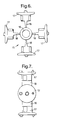
- the coupling member 15 is illustrated in detail in Figures 6 and 7 and will be seen to comprise a hub 16 which is received on the eccentric, a head 17 coupled to each diaphragm, and a connecting member 18 which connects each head to the hub 16.
- the connecting member 15 is a unitary plastics moulding. Whilst in the preferred embodiment of the invention the connecting member 15 comprises four heads and four associated connecting members, it will be appreciated that in other embodiments of the invention other numbers of heads and associated connecting members will be provided. In the most basic embodiment of the invention a single head 17 will be coupled to the hub 16 by a single connecting member 18. It is envisaged, however, that for most applications three or four pumping chambers will be required and the connecting member will accordingly either have three heads located angularly offset 120° from each other, or four heads angularly offset 90° from each other.
- the heads 17 may be coupled to the diaphragms by any convenient means.
- practical considerations make such a moulding extremely difficult in the case of a four chambered pump and, accordingly, at least in this embodiment, the diaphragms are formed separately from the connecting members and are secured thereto by suitable means.
- the means of securing the diaphragms to the connecting members are not critical to the present invention, and any suitable means may be employed.
- a diaphragm may be secured by adhesive or by welding to the head.
- a portion of the diaphragm is sandwiched between the head and a washer 19 which is itself secured to the head by means of a screw 20. It must be stressed, however, that this is merely a preferred method of securing the head to the diaphragm and that other methods are possible within the scope of the present invention.
- the use of a somewhat domed washer 19 is, however, particularly desirable since, as will be clear from the uppermost chamber of Figure 4, the use of a domed washer reduces the unswept volume of the pumping chamber at top dead centre and accordingly increases the compression ratio of the pump.
- the position of the heads, the shape of the diaphragm, and the deformation of the connecting members at a position of maximum crank offset is illustrated in the horizontally opposite chambers illustrated in Figure 4.
- the diaphragm will be somewhat deformed with the diaphragm portion 11A on one side of the head displaced towards its associated cover whilst the diaphragm portion 11B on the other side of the head is displaced somewhat towards the body.
- the head is tilted relevant to the longitudinal axis X-X of the relevant pumping chamber and the connecting member 18 is somewhat curved or bent to accommodate the articulation of the head.
- the crank shaft rotates the diaphragms will be reciprocated to effect the required pumping and the resultant articulation of the heads will be accommodated by flexible deformation of the diaphragms and the connecting members.
- the valving arrangements required to effect pumping are provided by portions of a diaphragm 11 which co-operate with seats provided on the covers 12 and the body portion 4B.
- a portion of the diaphragm located exterior to the pumping chamber 14 is formed with two-part circular slits 21 to form a pair of valve flaps 22, 23.
- the valve flap 23 co-operates with a seat 24 formed on the body part 4B to form an inlet valve.
- air will be drawn from the central chamber 9 through an inlet passage 25, through the seat 24, past the valve flap 23, and into the pumping chamber 14.
- the flap 23 will lie against the seat 24 to prevent reverse flow of air.
- the flap 22 co-operates with a seat 26 formed on the cover to provide an outlet valve.
- each of the pumping chambers is provided with such an arrangement of valves by its associated diaphragm.
- valve flaps 22, 23 which co-operate with seats 24, 26 provided by the body 4 and covers 12 respectively means that the valving required for operation of the pump is provided without the need for separate valve components. This considerably simplifies assembly of the pump, reduces cost, and, because the resultant valves are inherently quiet in operation, aids the reduction of noise generation by the pump.
- the body parts 4A, 4B, crank shaft 5, covers 12 and connecting member 15 are preferably provided by injection moulded plastic components.
- the diaphragms 11 may be stamped from suitable sheet plastic material having the required flexibility, resilience, and life expectancy.
Landscapes
- Engineering & Computer Science (AREA)
- Mechanical Engineering (AREA)
- General Engineering & Computer Science (AREA)
- Reciprocating Pumps (AREA)
Abstract
Description
- This invention relates to a diaphragm pump, that is to say to a pump having one or more pumping chambers each of which is defined on one side by a diaphragm which, in use, is moved repeatedly towards and away from the opposite side of the chamber to vary the volume of the chamber. Suitable valving is associated with the or each chamber so that working fluid is admitted to the chamber during movement of the diaphragm away from the opposite side of the chamber, and is expelled from the chamber during movement of the diaphragm towards the opposite side of the chamber.
- The particularly preferred embodiment of the present invention is concerned with the diaphragm pump suitable for pumping air at a relatively low volume rate. By appropriate design of the components of the diaphragm pump the preferred embodiment of the invention is able to operate at a very low noise level and is accordingly particularly suitable for use in environments in which a small volume of compressed air is required, and in which low noise levels are of critical importance. One typical application requiring these characteristics is the inflation of a pneumatic lumbar support cushion located, for example, in the seat of a car. It should be understood, however, that characteristics of the pump of the preferred embodiment render it suitable for other uses and the invention should not be construed as limited to small volume air pumps for use in the automotive industry.
- According to one aspect of the present invention there is provided a diaphragm pump comprising a pumping chamber which is defined on one side by a diaphragm which is movable, in use, towards and away from the opposite side of the pumping chamber to vary the volume of the pumping chamber; a crank shaft; and a coupling member coupling the diaphragm to the eccentric of the crank shaft so that as the crank shaft rotates in use the diaphragm is reciprocated to effect a cyclic variation in the volume of the pumping chamber, wherein the coupling member is provided by a unitary plastics moulding which comprises a hub which runs on the eccentric of the crank shaft, a head which is coupled to the diaphragm and a connecting member which connects the head to the hub, the connecting member being flexible to permit articulation of the head relative to the hub.
- The provision of the flexible connecting member, by permitting a small amount of articulation between the head and the hub, enables the head to be rigidly coupled to the diaphragm whilst permitting, by a combination of deformation of the diaphragm and flexing of the connecting member, the hub to follow the eccentric as the crank shaft rotates. Accordingly, the pump may be constructed in such a manner that the only connections between components which require relative sliding or translational motion are the bearing connection between the hub and the eccentric, and the bearings in which the crank shaft is mounted. Elimination of other sliding and rotational contacts considerably simplifies construction of the pump, reduces possible noise generation and eliminates the potential for wear. Thus, the pump of the preferred embodiment may be made in a relatively economic manner, can be made very quiet, and will significantly resist deterioration in both performance and noise generation due to component wear during the life of the pump. These characteristics combine to make the pump particularly suitable for use in the automotive industry where low noise levels and long life expectancy are particularly important characteristics for components.
- In a particularly preferred embodiment of the invention the diaphragm pump has a plurality of pumping chambers each of which is defined on one side by a diaphragm which, in use, is movable towards and away from the opposite side of its associated chamber to vary the volume of that chamber. Each diaphragm has associated therewith a coupling member which couples the diaphragm to a common eccentric. In a particularly preferred embodiment of the invention the coupling members are provided by a single unitary plastics moulding which comprises a single hub, the respective heads, and respective connecting members connecting each head to the hub, the connecting members all being flexible to permit articulation of the heads relative to the hub. With such a construction, a three, four or more chambered pump can be constructed in which the only sliding contact is between the eccentric of a common crank shaft and its associated hub, and the bearings in which the crank shaft is mounted.
- In accordance with another aspect of the present invention a diaphragm pump comprises a body in which a crank shaft is rotatably mounted; a cover secured to the body, a portion of the cover defining one side of a pumping chamber; a diaphragm mounted sandwiched between the cover and the body to define the other side of a pumping chamber; a coupling member coupling the diaphragm to the eccentric of the crank shaft so that, in use, as the crank shaft rotates the diaphragm is reciprocated to effect a cyclic variation in the volume of the pumping chamber; and inlet and outlet valves for controlling ingress of working fluid to the pumping chamber and egress of working fluid from the pumping chamber respectively, wherein the movable members of the inlet and outlet valves are defined by portions of the diaphragm which are located exterior to the pumping chamber and which co-operate with valve seats defined by the cover and the body.
- The use of portions of the diaphragm as the moveable members of both the inlet and outlet valves obviates the need for separate moveable valve components. Conveniently, the portions of the diaphragm can be in the form of flaps which co-operates with the seats to prevent flow through the valves when the flaps are in engagement with the seats, and to permit flow through the valves when the flaps are spaced from the seats. By forming the seats on the body and the cover, and by using portions of the diaphragm as the moveable components of the valves, the inlet and outlet valves are provided without the use of any separate valve components. This leads to a particularly simple construction in which a pump can be constructed from only five components viz a body, a crank shaft, a cover, a diaphragm and a coupling member for coupling the diaphragm to the eccentric of the crank shaft. Elimination of separate valve components considerably simplifies the construction and assembly of the pump, leads to reduced noise generation, and improved life expectancy.
- In a particularly preferred embodiment of the invention a pump comprises four pumping chambers. Such a pump can conveniently be provided with a body which is substantially square in transverse cross-section and in which the crank shaft is mounted to rotate about an axis located at the intersection of the diagonals of the transverse cross-section. A cover is secured to and substantially covers each of the four exterior faces of the body. A diaphragm is sandwiched between each cover and the body and a respective pumping chamber is defined between each diaphragm and its associated cover. Accordingly, the pump has four pumping chambers which, when viewed in transverse cross-section, are located 90° offset from each other. With this arrangement, any noise generated at the crank shaft bearings or at the bearing between the eccentric of the crank shaft and the hub will be substantially attenuated by the body itself, the pumping chambers and the covers so that any noise escaping to the exterior of the body will be substantially less than the noise generated within the body. This arrangement additionally reduces the noise audible from the exterior of the pump.
- Preferably, the body itself is formed by two moulded plastic components which, when assembled together, locate the crank shaft so that no additional means of axially locating the crank shaft is required. The covers may constitute the sole means of holding the body parts together so that the act of securing the covers in position simultaneously holds the body parts together. Preferably, however, the body is secured to the body of an associated electric motor by means of two or more screws which extend through the body parts in a direction parallel to the axis of rotation of the crank shaft. Such screws, in addition to mounting the pump on the electric motor serve to secure together the body parts.
- In a particularly preferred embodiment of the invention one of the body parts includes means for engaging the body of an associated electric motor and the other of the body parts includes an outlet port which, by means of galleries internal to the body part, is connected to the outlet valves of all of the pumping chambers. Preferably, inlet air for the pumping chambers is derived from the interior portion of the body in which the crank shaft is located. Air is in turn drawn into this interior chamber via the associated electric motor. Thus, in use, air to be pumped is drawn through the motor and through the crank shaft body chamber to effect cooling of these components.
- The invention will be better understood from the following description of a preferred embodiment thereof, given by way of example only, reference being had to the accompanying drawings wherein:
- Figure 1 is a side view of a preferred embodiment of a motor driven pump according to the present invention with one cover removed to expose the underlying diaphragm and body;
- Figure 2 is an end view of the pump of Figure 1;
- Figure 3 is a cross-section on the line A-A of Figure 1;
- Figure 4 is a cross-section on the line B-B of Figure 1;
- Figure 5 is a cross-section on the line C-C of Figure 2; and
- Figures 6 and 7 show respectively an end view and side view of the coupling member of the embodiment of Figures 1-5.
- The illustrated motor driven
pump 1 comprises anelectric motor 2 having mounted thereon apump assembly 3. The pump assembly comprises abody 4 formed by afirst body part 4A which is mounted on themotor 2 to support the pump assembly on the motor, and asecond body part 4B. Thebody parts crank shaft 5 having aneccentric portion 6 is mounted in the body by way of abearing 7 and is coupled to theoutput shaft 8 of themotor 2 for rotation therewith. Thecrank shaft 5 is located within aninterior chamber 9 defined by thebody 4. - As best seen in Figures 2 and 4, the body is generally square in exterior transverse cross-section and presents four exterior faces, each identical to the
face 10 visible in Figure 1. In the complete assembly, each face is covered by adiaphragm 11 which substantially covers the entire area of the face. In the illustrated embodiment of the invention the diaphragm is transparent and accordingly details of theface 10 are visible in Figure 1 through the diaphragm. Arespective cover 12 overlies each diaphragm and is secured to the underlying body bysuitable fastenings 13. It will be appreciated that thecovers 12 are secured to bothbody parts - A
pumping chamber 14 is defined between each diaphragm and itsassociated cover 12, a respective diaphragm forming one side of each respective pumping chamber and the interior wall of the associated cover forming the opposite wall of the respective pumping chamber. In use, the diaphragms reciprocate between a bottom dead centre position as illustrated for thelowest chamber 14 of Figure 4 and a top dead centre position as illustrated for theuppermost chamber 14 of Figure 4. Appropriate valving (described in more detail below) is provided to control ingress and egress of fluid so that as the diaphragms reciprocate fluid is pumped. - To effect the required reciprocating movement of the diaphragms each
diaphragm 11 is coupled to the eccentric 6 of the crank shaft by acoupling member 15. Thecoupling member 15 is illustrated in detail in Figures 6 and 7 and will be seen to comprise ahub 16 which is received on the eccentric, ahead 17 coupled to each diaphragm, and a connectingmember 18 which connects each head to thehub 16. The connectingmember 15 is a unitary plastics moulding. Whilst in the preferred embodiment of the invention the connectingmember 15 comprises four heads and four associated connecting members, it will be appreciated that in other embodiments of the invention other numbers of heads and associated connecting members will be provided. In the most basic embodiment of the invention asingle head 17 will be coupled to thehub 16 by a single connectingmember 18. It is envisaged, however, that for most applications three or four pumping chambers will be required and the connecting member will accordingly either have three heads located angularly offset 120° from each other, or four heads angularly offset 90° from each other. - The
heads 17 may be coupled to the diaphragms by any convenient means. In some embodiments of the invention it may be possible to mould the diaphragms integrally with the heads. However, practical considerations make such a moulding extremely difficult in the case of a four chambered pump and, accordingly, at least in this embodiment, the diaphragms are formed separately from the connecting members and are secured thereto by suitable means. The means of securing the diaphragms to the connecting members are not critical to the present invention, and any suitable means may be employed. For example, in certain applications a diaphragm may be secured by adhesive or by welding to the head. In the preferred embodiment of the invention, however, a portion of the diaphragm is sandwiched between the head and awasher 19 which is itself secured to the head by means of ascrew 20. It must be stressed, however, that this is merely a preferred method of securing the head to the diaphragm and that other methods are possible within the scope of the present invention. The use of a somewhatdomed washer 19 is, however, particularly desirable since, as will be clear from the uppermost chamber of Figure 4, the use of a domed washer reduces the unswept volume of the pumping chamber at top dead centre and accordingly increases the compression ratio of the pump. - As will be appreciated by those skilled in the art, as the crank shaft is rotated the head connected to each diaphragm will be subject to both longitudinal forces (i.e. forces in the direction of reciprocation of the diaphragm for the respective pumping chamber) and also to transverse forces occasioned by the translational movement of the centre of the eccentric as the crank shaft rotates. In conventional reciprocating piston devices the application of transverse forces to the piston is reduced or substantially eliminated by use of a bearing between the connecting rod and the piston and the piston is constrained to remain parallel to the axis of its cylinder. In the case of the present invention, however, transverse movement of the eccentric is accommodated by a combination of tilting movement of the head and flexible deformation of the connecting member. The position of the heads, the shape of the diaphragm, and the deformation of the connecting members at a position of maximum crank offset is illustrated in the horizontally opposite chambers illustrated in Figure 4. As shown, the diaphragm will be somewhat deformed with the
diaphragm portion 11A on one side of the head displaced towards its associated cover whilst thediaphragm portion 11B on the other side of the head is displaced somewhat towards the body. The head is tilted relevant to the longitudinal axis X-X of the relevant pumping chamber and the connectingmember 18 is somewhat curved or bent to accommodate the articulation of the head. Thus, as the crank shaft rotates the diaphragms will be reciprocated to effect the required pumping and the resultant articulation of the heads will be accommodated by flexible deformation of the diaphragms and the connecting members. - According to one aspect of the present invention the valving arrangements required to effect pumping are provided by portions of a
diaphragm 11 which co-operate with seats provided on thecovers 12 and thebody portion 4B. - Referring to Figure 1 it will be noted that a portion of the diaphragm located exterior to the
pumping chamber 14 is formed with two-part circular slits 21 to form a pair of valve flaps 22, 23. Thevalve flap 23 co-operates with aseat 24 formed on thebody part 4B to form an inlet valve. When the associated diaphragm is moving from top dead centre to bottom dead centre air will be drawn from thecentral chamber 9 through aninlet passage 25, through theseat 24, past thevalve flap 23, and into the pumpingchamber 14. During the following pumping stroke theflap 23 will lie against theseat 24 to prevent reverse flow of air. Theflap 22 co-operates with a seat 26 formed on the cover to provide an outlet valve. During pumping strokes of the associated diaphragm theflap 22 will lift away from the seat 26 to permit air to flow into agallery 27 which is connected to anoutlet port 28. During the following suction stroke of the diaphragm theflap 22 will sit against the seat 26 to prevent reverse flow of air. Each of the pumping chambers is provided with such an arrangement of valves by its associated diaphragm. - It will be appreciated that the use of portions of the diaphragms to provide valve flaps 22, 23 which co-operate with
seats 24, 26 provided by thebody 4 and covers 12 respectively means that the valving required for operation of the pump is provided without the need for separate valve components. This considerably simplifies assembly of the pump, reduces cost, and, because the resultant valves are inherently quiet in operation, aids the reduction of noise generation by the pump. - The
body parts shaft 5, covers 12 and connectingmember 15 are preferably provided by injection moulded plastic components. Thediaphragms 11 may be stamped from suitable sheet plastic material having the required flexibility, resilience, and life expectancy.
Claims (8)
- A diaphragm pump comprising a pumping chamber which is defined on one side by a diaphragm which is movable, in use, towards and away from the opposite side of the pumping chamber to vary the volume of the pumping chamber; a crank shaft; and a coupling member coupling the diaphragm to the eccentric of the crank shaft so that as the crank shaft rotates in use the diaphragm is reciprocated to effect a cyclic variation in the volume of the pumping chamber, wherein the coupling member is provided by a unitary plastics moulding which comprises a hub which runs on the eccentric of the crank shaft, a head which is coupled to the diaphragm and a connecting member which connects the head to the hub, the connecting member being flexible to permit articulation of the head relative to the hub.
- A diaphragm pump according to claim 1 wherein the diaphragm pump has a plurality of pumping chambers each of which is defined on one side by a diaphragm which, in use, is movable towards and away from the opposite side of its associated chamber to vary the volume of that chamber, and wherein each diaphragm has associated therewith a coupling member which couples the diaphragm to a common eccentric.
- A diaphragm pump according to claim 2 wherein the coupling members are provided by a single unitary plastics moulding which comprises a single hub, the respective heads, and respective connecting members connecting each head to the hub, the connecting members all being flexible to permit articulation of the heads relative to the hub.
- A diaphragm pump according to any preceding claim wherein inlet and outlet valves are provided for controlling ingress of working fluid to the pumping chamber and egress of working fluid from the pumping chamber respectively, wherein the movable members of the inlet and outlet valves are defined by portions of the diaphragm which are located exterior to the pumping chamber and which co-operate with valve seats defined by the cover and the body.
- A diaphragm pump according to any preceding claim wherein the pump comprises four pumping chambers and comprises a body which is substantially square in transverse cross-section and in which the crank shaft is mounted to rotate about an axis located at the intersection of the diagonals of the transverse cross-section; a cover secured to and substantially covering each of the four exterior faces of the body, and a diaphragm sandwiched between each cover and the body and a respective pumping chamber is defined between each diaphragm and its associated cover.
- A diaphragm pump according to claim 5 wherein the body is formed by two moulded plastic components which, when assembled together, locate the crank shaft so that no additional means of axially locating the crank shaft is required.
- A diaphragm pump according to claim 6 wherein one of the body parts includes means for engaging the body of an associated electric motor and the other of the body parts includes an outlet port which, by means of galleries internal to the body part, is connected to the outlet valves of all of the pumping chambers.
- A diaphragm pump according to claim 7 wherein inlet air·for the pumping chambers is derived from the interior portion of the body in which the crank shaft is located and air is in turn drawn into this interior chamber via the associated electric motor.
Applications Claiming Priority (2)
| Application Number | Priority Date | Filing Date | Title |
|---|---|---|---|
| GB9509773A GB2301151B (en) | 1995-05-15 | 1995-05-15 | Diaphragm pump |
| GB9509773 | 1995-05-15 |
Publications (2)
| Publication Number | Publication Date |
|---|---|
| EP0743452A1 true EP0743452A1 (en) | 1996-11-20 |
| EP0743452B1 EP0743452B1 (en) | 2001-11-07 |
Family
ID=10774470
Family Applications (1)
| Application Number | Title | Priority Date | Filing Date |
|---|---|---|---|
| EP96303301A Expired - Lifetime EP0743452B1 (en) | 1995-05-15 | 1996-05-13 | Diaphragm pump |
Country Status (3)
| Country | Link |
|---|---|
| EP (1) | EP0743452B1 (en) |
| DE (1) | DE69616648T2 (en) |
| GB (1) | GB2301151B (en) |
Cited By (12)
| Publication number | Priority date | Publication date | Assignee | Title |
|---|---|---|---|---|
| WO2007090764A1 (en) * | 2006-02-10 | 2007-08-16 | Continental Teves Ag & Co. Ohg | Motor/pump assembly |
| EP1877710A1 (en) * | 2005-04-21 | 2008-01-16 | Industrial Research Limited | Pressure wave generator |
| DE102007020538A1 (en) * | 2007-01-29 | 2008-10-02 | Continental Teves Ag & Co. Ohg | Motor-pump arrangement for preparing the pressure for a brake actuating device of a vehicle braking system comprises a motor shaft and an eccentric shaft arranged in a first storage unit and a second storage unit |
| WO2009103217A1 (en) * | 2008-02-20 | 2009-08-27 | 常州富邦电气有限公司 | A multi-stage diaphragm pump |
| CN102913424A (en) * | 2011-08-04 | 2013-02-06 | 应研精工株式会社 | Diaphragm pump |
| US8984898B2 (en) | 2005-04-21 | 2015-03-24 | Industrial Research Limited | Cryogenic refrigerator system with pressure wave generator |
| CN102257274B (en) * | 2008-12-19 | 2015-05-13 | 大陆-特韦斯贸易合伙股份公司及两合公司 | Motor-pump assembly |
| WO2018037443A1 (en) * | 2016-08-22 | 2018-03-01 | 柴田科学株式会社 | Multi-cylinder diaphragm pump |
| JP2020133487A (en) * | 2019-02-19 | 2020-08-31 | 柴田科学株式会社 | Four-cylinder type diaphragm pump |
| CN112682390A (en) * | 2020-12-29 | 2021-04-20 | 焦作市虹桥制动器股份有限公司 | Electric pneumatic driving unit |
| DE102006060645B4 (en) | 2006-02-10 | 2021-11-04 | Continental Teves Ag & Co. Ohg | Motor-pump unit |
| CN114439732A (en) * | 2020-11-03 | 2022-05-06 | 深圳安吉尔饮水产业集团有限公司 | Pump head of diaphragm booster pump, water purifier and pump head working method |
Families Citing this family (2)
| Publication number | Priority date | Publication date | Assignee | Title |
|---|---|---|---|---|
| DE102007028351B4 (en) * | 2007-06-20 | 2013-01-17 | Knf Flodos Ag | diaphragm pump |
| EP2365220B1 (en) | 2010-03-03 | 2017-08-23 | Kongsberg Automotive AB | Linear pump |
Citations (7)
| Publication number | Priority date | Publication date | Assignee | Title |
|---|---|---|---|---|
| FR1388721A (en) * | 1963-10-07 | 1965-02-12 | Diaphragm compressor | |
| GB1038576A (en) * | 1963-04-18 | 1966-08-10 | Becker Erich | Improvements in or relating to diaphragm pumps |
| DE1907454A1 (en) * | 1968-02-22 | 1969-09-11 | Roach Timothy James Francis | Diaphragm pump |
| US4310107A (en) * | 1975-10-29 | 1982-01-12 | The Afa Corporation | Manually operated, trigger actuated diaphragm pump dispenser |
| DE3801515A1 (en) * | 1987-01-20 | 1988-07-28 | Thomas Industries Inc | Compressor for fluids, in particular diaphragm air compressor |
| WO1991014099A1 (en) * | 1990-03-16 | 1991-09-19 | Robert Bosch Gmbh | Double-membrane pump |
| WO1992018769A1 (en) * | 1991-04-10 | 1992-10-29 | Gentec B.V. | Radial pump |
Family Cites Families (5)
| Publication number | Priority date | Publication date | Assignee | Title |
|---|---|---|---|---|
| US3847513A (en) * | 1969-02-10 | 1974-11-12 | Gale W Inc | Air pump |
| US4381179A (en) * | 1980-10-31 | 1983-04-26 | Lear Siegler, Inc. | Pumps with floating wrist pins |
| US4411603A (en) * | 1981-06-24 | 1983-10-25 | Cordis Dow Corp. | Diaphragm type blood pump for medical use |
| US4842498A (en) * | 1987-01-20 | 1989-06-27 | Thomas Industries, Inc. | Diaphragm compressor |
| GB9320342D0 (en) * | 1993-10-02 | 1993-11-24 | Munster Simms Engineering Limi | Diaphragm pump |
-
1995
- 1995-05-15 GB GB9509773A patent/GB2301151B/en not_active Expired - Fee Related
-
1996
- 1996-05-13 EP EP96303301A patent/EP0743452B1/en not_active Expired - Lifetime
- 1996-05-13 DE DE69616648T patent/DE69616648T2/en not_active Expired - Lifetime
Patent Citations (7)
| Publication number | Priority date | Publication date | Assignee | Title |
|---|---|---|---|---|
| GB1038576A (en) * | 1963-04-18 | 1966-08-10 | Becker Erich | Improvements in or relating to diaphragm pumps |
| FR1388721A (en) * | 1963-10-07 | 1965-02-12 | Diaphragm compressor | |
| DE1907454A1 (en) * | 1968-02-22 | 1969-09-11 | Roach Timothy James Francis | Diaphragm pump |
| US4310107A (en) * | 1975-10-29 | 1982-01-12 | The Afa Corporation | Manually operated, trigger actuated diaphragm pump dispenser |
| DE3801515A1 (en) * | 1987-01-20 | 1988-07-28 | Thomas Industries Inc | Compressor for fluids, in particular diaphragm air compressor |
| WO1991014099A1 (en) * | 1990-03-16 | 1991-09-19 | Robert Bosch Gmbh | Double-membrane pump |
| WO1992018769A1 (en) * | 1991-04-10 | 1992-10-29 | Gentec B.V. | Radial pump |
Cited By (22)
| Publication number | Priority date | Publication date | Assignee | Title |
|---|---|---|---|---|
| EP1877710A4 (en) * | 2005-04-21 | 2010-12-15 | Ind Res Ltd | Pressure wave generator |
| EP1877710A1 (en) * | 2005-04-21 | 2008-01-16 | Industrial Research Limited | Pressure wave generator |
| US8984898B2 (en) | 2005-04-21 | 2015-03-24 | Industrial Research Limited | Cryogenic refrigerator system with pressure wave generator |
| JP2008542671A (en) * | 2005-04-21 | 2008-11-27 | インダストリアル リサーチ リミテッド | Pressure wave generator |
| US8171742B2 (en) | 2005-04-21 | 2012-05-08 | Industrial Research Limited | Pressure wave generator |
| KR101303489B1 (en) | 2006-02-10 | 2013-09-03 | 콘티넨탈 테베스 아게 운트 코. 오하게 | Motor/pump assembly |
| DE102006060645B4 (en) | 2006-02-10 | 2021-11-04 | Continental Teves Ag & Co. Ohg | Motor-pump unit |
| CN101384459B (en) * | 2006-02-10 | 2010-10-13 | 大陆-特韦斯贸易合伙股份公司及两合公司 | Motor pump assembly |
| WO2007090764A1 (en) * | 2006-02-10 | 2007-08-16 | Continental Teves Ag & Co. Ohg | Motor/pump assembly |
| US8702180B2 (en) | 2006-02-10 | 2014-04-22 | Continental Teves Ag & Co. Ohg | Motor/pump assembly |
| DE102007020538A1 (en) * | 2007-01-29 | 2008-10-02 | Continental Teves Ag & Co. Ohg | Motor-pump arrangement for preparing the pressure for a brake actuating device of a vehicle braking system comprises a motor shaft and an eccentric shaft arranged in a first storage unit and a second storage unit |
| WO2009103217A1 (en) * | 2008-02-20 | 2009-08-27 | 常州富邦电气有限公司 | A multi-stage diaphragm pump |
| CN102257274B (en) * | 2008-12-19 | 2015-05-13 | 大陆-特韦斯贸易合伙股份公司及两合公司 | Motor-pump assembly |
| CN102913424B (en) * | 2011-08-04 | 2015-06-24 | 应研精工株式会社 | Diaphragm pump |
| EP2554846A1 (en) * | 2011-08-04 | 2013-02-06 | Okenseiko Co., Ltd. | Diaphragm pump |
| US9341176B2 (en) | 2011-08-04 | 2016-05-17 | Okenseiko Co., Ltd. | Diaphragm pump |
| CN102913424A (en) * | 2011-08-04 | 2013-02-06 | 应研精工株式会社 | Diaphragm pump |
| WO2018037443A1 (en) * | 2016-08-22 | 2018-03-01 | 柴田科学株式会社 | Multi-cylinder diaphragm pump |
| JP2020133487A (en) * | 2019-02-19 | 2020-08-31 | 柴田科学株式会社 | Four-cylinder type diaphragm pump |
| US11939971B2 (en) | 2019-02-19 | 2024-03-26 | Sibata Scientific Technology Ltd. | Four-cylinder diaphragm pump |
| CN114439732A (en) * | 2020-11-03 | 2022-05-06 | 深圳安吉尔饮水产业集团有限公司 | Pump head of diaphragm booster pump, water purifier and pump head working method |
| CN112682390A (en) * | 2020-12-29 | 2021-04-20 | 焦作市虹桥制动器股份有限公司 | Electric pneumatic driving unit |
Also Published As
| Publication number | Publication date |
|---|---|
| GB2301151A (en) | 1996-11-27 |
| DE69616648T2 (en) | 2002-05-08 |
| GB2301151B (en) | 1999-02-03 |
| EP0743452B1 (en) | 2001-11-07 |
| GB9509773D0 (en) | 1995-07-05 |
| DE69616648D1 (en) | 2001-12-13 |
Similar Documents
| Publication | Publication Date | Title |
|---|---|---|
| EP0743452B1 (en) | Diaphragm pump | |
| US6048183A (en) | Diaphragm pump with modified valves | |
| KR100739042B1 (en) | Diaphragm-type vacuum pump | |
| US4801249A (en) | Small-sized pump | |
| US5791882A (en) | High efficiency diaphragm pump | |
| US6264438B1 (en) | Reciprocating pump having a ball drive | |
| KR19990067229A (en) | Piston pump | |
| US4242061A (en) | Double diaphragm pump | |
| KR20010023788A (en) | Small pump device and sphygmomanometer using the pump device | |
| JP4131459B2 (en) | Diaphragm pump for liquid | |
| EP1034373A1 (en) | Diaphragm pump with modified valves | |
| JPH08100761A (en) | Connecting rod for multiple compressor pump | |
| JPH074487A (en) | Crank driving mechanism | |
| JP3200693B2 (en) | Diaphragm pump | |
| JP4074980B2 (en) | Diaphragm pump | |
| JPH0791367A (en) | Vacuum pump device | |
| JP3235977U (en) | Two-stage compression type compressor | |
| JP4161302B2 (en) | Diaphragm pump | |
| JP3870356B2 (en) | Diaphragm pump | |
| JP2003269337A (en) | Diaphragm pump | |
| JP3521335B2 (en) | Reciprocating pump | |
| JP2001295756A (en) | Compressor | |
| CN213981127U (en) | Micro fluid pump and pressure fluid application equipment | |
| KR0129267Y1 (en) | Oil pump using an eccentric cam | |
| KR200187031Y1 (en) | Suction valve of reciprocating compressor |
Legal Events
| Date | Code | Title | Description |
|---|---|---|---|
| PUAI | Public reference made under article 153(3) epc to a published international application that has entered the european phase |
Free format text: ORIGINAL CODE: 0009012 |
|
| AK | Designated contracting states |
Kind code of ref document: A1 Designated state(s): DE ES FR IT NL PT SE |
|
| 17P | Request for examination filed |
Effective date: 19970418 |
|
| RAP1 | Party data changed (applicant data changed or rights of an application transferred) |
Owner name: TEXTRON AUTOMOTIVE COMPANY LIMITED |
|
| 17Q | First examination report despatched |
Effective date: 19990812 |
|
| GRAG | Despatch of communication of intention to grant |
Free format text: ORIGINAL CODE: EPIDOS AGRA |
|
| GRAG | Despatch of communication of intention to grant |
Free format text: ORIGINAL CODE: EPIDOS AGRA |
|
| GRAH | Despatch of communication of intention to grant a patent |
Free format text: ORIGINAL CODE: EPIDOS IGRA |
|
| GRAH | Despatch of communication of intention to grant a patent |
Free format text: ORIGINAL CODE: EPIDOS IGRA |
|
| RAP1 | Party data changed (applicant data changed or rights of an application transferred) |
Owner name: CTEX SEAT COMFORT LIMITED |
|
| GRAA | (expected) grant |
Free format text: ORIGINAL CODE: 0009210 |
|
| AK | Designated contracting states |
Kind code of ref document: B1 Designated state(s): DE ES FR IT NL PT SE |
|
| PG25 | Lapsed in a contracting state [announced via postgrant information from national office to epo] |
Ref country code: NL Free format text: LAPSE BECAUSE OF FAILURE TO SUBMIT A TRANSLATION OF THE DESCRIPTION OR TO PAY THE FEE WITHIN THE PRESCRIBED TIME-LIMIT Effective date: 20011107 |
|
| REF | Corresponds to: |
Ref document number: 69616648 Country of ref document: DE Date of ref document: 20011213 |
|
| PG25 | Lapsed in a contracting state [announced via postgrant information from national office to epo] |
Ref country code: SE Free format text: LAPSE BECAUSE OF FAILURE TO SUBMIT A TRANSLATION OF THE DESCRIPTION OR TO PAY THE FEE WITHIN THE PRESCRIBED TIME-LIMIT Effective date: 20020207 Ref country code: PT Free format text: LAPSE BECAUSE OF FAILURE TO SUBMIT A TRANSLATION OF THE DESCRIPTION OR TO PAY THE FEE WITHIN THE PRESCRIBED TIME-LIMIT Effective date: 20020207 |
|
| NLV1 | Nl: lapsed or annulled due to failure to fulfill the requirements of art. 29p and 29m of the patents act | ||
| PG25 | Lapsed in a contracting state [announced via postgrant information from national office to epo] |
Ref country code: ES Free format text: LAPSE BECAUSE OF FAILURE TO SUBMIT A TRANSLATION OF THE DESCRIPTION OR TO PAY THE FEE WITHIN THE PRESCRIBED TIME-LIMIT Effective date: 20020530 |
|
| PLBE | No opposition filed within time limit |
Free format text: ORIGINAL CODE: 0009261 |
|
| STAA | Information on the status of an ep patent application or granted ep patent |
Free format text: STATUS: NO OPPOSITION FILED WITHIN TIME LIMIT |
|
| 26N | No opposition filed | ||
| PGFP | Annual fee paid to national office [announced via postgrant information from national office to epo] |
Ref country code: IT Payment date: 20080527 Year of fee payment: 13 |
|
| REG | Reference to a national code |
Ref country code: FR Ref legal event code: ST Effective date: 20100129 |
|
| PG25 | Lapsed in a contracting state [announced via postgrant information from national office to epo] |
Ref country code: FR Free format text: LAPSE BECAUSE OF NON-PAYMENT OF DUE FEES Effective date: 20090602 |
|
| PGFP | Annual fee paid to national office [announced via postgrant information from national office to epo] |
Ref country code: FR Payment date: 20080425 Year of fee payment: 13 |
|
| PG25 | Lapsed in a contracting state [announced via postgrant information from national office to epo] |
Ref country code: IT Free format text: LAPSE BECAUSE OF NON-PAYMENT OF DUE FEES Effective date: 20090513 |
|
| REG | Reference to a national code |
Ref country code: DE Ref legal event code: R082 Ref document number: 69616648 Country of ref document: DE Representative=s name: GRUENECKER, KINKELDEY, STOCKMAIR & SCHWANHAEUS, DE |
|
| REG | Reference to a national code |
Ref country code: DE Ref legal event code: R082 Ref document number: 69616648 Country of ref document: DE Representative=s name: GRUENECKER PATENT- UND RECHTSANWAELTE PARTG MB, DE Effective date: 20120423 Ref country code: DE Ref legal event code: R082 Ref document number: 69616648 Country of ref document: DE Representative=s name: GRUENECKER, KINKELDEY, STOCKMAIR & SCHWANHAEUS, DE Effective date: 20120423 Ref country code: DE Ref legal event code: R081 Ref document number: 69616648 Country of ref document: DE Owner name: KONGSBERG AUTOMOTIVE SP. Z O.O., PL Free format text: FORMER OWNER: CTEX SEAT COMFORT LTD., BURTON ON TRENT, STAFFORDSHIRE, GB Effective date: 20120423 |
|
| PGFP | Annual fee paid to national office [announced via postgrant information from national office to epo] |
Ref country code: DE Payment date: 20130515 Year of fee payment: 18 |
|
| REG | Reference to a national code |
Ref country code: DE Ref legal event code: R119 Ref document number: 69616648 Country of ref document: DE |
|
| REG | Reference to a national code |
Ref country code: DE Ref legal event code: R119 Ref document number: 69616648 Country of ref document: DE Effective date: 20141202 |
|
| PG25 | Lapsed in a contracting state [announced via postgrant information from national office to epo] |
Ref country code: DE Free format text: LAPSE BECAUSE OF NON-PAYMENT OF DUE FEES Effective date: 20141202 |