EP0744190B1 - Implantable antitachycardia stimulation device - Google Patents
Implantable antitachycardia stimulation device Download PDFInfo
- Publication number
- EP0744190B1 EP0744190B1 EP96303751A EP96303751A EP0744190B1 EP 0744190 B1 EP0744190 B1 EP 0744190B1 EP 96303751 A EP96303751 A EP 96303751A EP 96303751 A EP96303751 A EP 96303751A EP 0744190 B1 EP0744190 B1 EP 0744190B1
- Authority
- EP
- European Patent Office
- Prior art keywords
- signal
- rate
- sensor signal
- zone threshold
- sensor
- Prior art date
- Legal status (The legal status is an assumption and is not a legal conclusion. Google has not performed a legal analysis and makes no representation as to the accuracy of the status listed.)
- Expired - Lifetime
Links
Images

Classifications
-
- A—HUMAN NECESSITIES
- A61—MEDICAL OR VETERINARY SCIENCE; HYGIENE
- A61N—ELECTROTHERAPY; MAGNETOTHERAPY; RADIATION THERAPY; ULTRASOUND THERAPY
- A61N1/00—Electrotherapy; Circuits therefor
- A61N1/18—Applying electric currents by contact electrodes
- A61N1/32—Applying electric currents by contact electrodes alternating or intermittent currents
- A61N1/36—Applying electric currents by contact electrodes alternating or intermittent currents for stimulation
- A61N1/362—Heart stimulators
- A61N1/365—Heart stimulators controlled by a physiological parameter, e.g. heart potential
- A61N1/36514—Heart stimulators controlled by a physiological parameter, e.g. heart potential controlled by a physiological quantity other than heart potential, e.g. blood pressure
-
- A—HUMAN NECESSITIES
- A61—MEDICAL OR VETERINARY SCIENCE; HYGIENE
- A61N—ELECTROTHERAPY; MAGNETOTHERAPY; RADIATION THERAPY; ULTRASOUND THERAPY
- A61N1/00—Electrotherapy; Circuits therefor
- A61N1/18—Applying electric currents by contact electrodes
- A61N1/32—Applying electric currents by contact electrodes alternating or intermittent currents
- A61N1/36—Applying electric currents by contact electrodes alternating or intermittent currents for stimulation
- A61N1/362—Heart stimulators
- A61N1/3621—Heart stimulators for treating or preventing abnormally high heart rate
Definitions
- the present invention relates to implantable medical devices and methods, and more particularly to an implantable antitachycardia device, e.g., an antitachycardia pacemaker or defibrillator-cardioverter, that automatically adjusts its detection rate threshold as a function of the sensed cardiac rate.
- an implantable antitachycardia device e.g., an antitachycardia pacemaker or defibrillator-cardioverter, that automatically adjusts its detection rate threshold as a function of the sensed cardiac rate.
- Antitachycardia therapy devices such as antitachycardia pacemakers or antitachycardia defibrillators-cardioverters, utilize heart rate detection circuitry to determine the onset of a cardiac arrhythmia.
- Such rate detection circuitry typically includes discrete rate zones for the classification of arrhythmias.
- the rate zones which are typically set through one or more user programmable parameters, dictate what type of device response, i.e., what type of antitachycardia therapy, will be provided whenever the detected heart rate falls within a given rate zone.
- a user may define a low rate ventricular tachycardia zone which is identified by a low rate limit, rate A (e.g., 135 bpm), and a high rate limit, rate B (e.g., 175 bpm). Any detected heart rate that falls within this zone would thus be identified as a low rate ventricular tachycardia, and such identification would trigger an appropriate therapy from the antitachycardia therapy device.
- a high rate tachycardia classification zone e.g., between 175 and 240 bpm, may be defined that boarders the low rate tachycardia zone.
- any detected heart rate that falls within the high rate tachycardia zone would be identified as a high rate ventricular tachycardia, thereby triggering another type of therapy from the antitachycardia therapy device.
- a third zone may be added just above the high rate tachycardia zone.
- the user can set up a single large rate zone or as many smaller bordering rate zones as desired, with each rate zone providing a particular one of a variety of independent antitachycardia therapies that is automatically applied by the device in order to terminate a perceived arrhythmia.
- the detection and classification of arrhythmias may be further based on additional parameters, in addition to heart rate, such as the hemodynamics identified by a particular sensor, and/or other rate parameters, such as the onset, stability or duration of the detected heart rate.
- the selection of discrete rate zones may prove to be problematic when a patient has a normal sinus rate that enters into one of the tachycardia zones during exercise or during other periods of physiological stress.
- various discriminating parameters such as the onset and stability of the detected rate or rhythm, may be used in an attempt to minimize the detection of a fast normal sinus rate as a tachycardia rate, the fast rhythm or rate may still be incorrectly classified as an arrhythmia, resulting in antitachycardia therapy being provided by the device.
- antitachycardia therapy could be inappropriate, and even dangerous, because it may actually induce an actual arrhythmia when provided incorrectly.
- rate detection circuitry in an antitachycardia pacemaker or defibrillator- cardioverter that minimizes the risk of incorrectly identifying and classifying a fast sinus rate (for which antitachycardia therapy is not needed nor desired) as an arrhythmia (for which antitachycardia therapy is needed and desired).
- US 4,940,052 describes a rate-responsive pacemaker which includes a pulse generator, a physiological sensor and a processor, which generates stimulation pulses on demand, and threshold means arranged to generate a threshold signal as a function of a signal representative of a sensed physiological parameter.
- the physiological sensor generates a raw signal which varies as a function of a physiological parameter to provide an indication as to whether the heart rate should increase or decrease and therefore whether the pacemaker should change the rate at which pulses are provided.
- EP-A-580128 discloses a stimulation device having a first sensor which generates a signal indicative of a patient's ECG, and a second sensor in the form of an activity sensor which generates a signal representing the physical status of the patient.
- An evaluation system establishes heart rate criteria for recognising pathological tachycardias to be applied against the ECG signal to recognise pathological tachycardia and distinguish it from physiological tachycardia.
- Yet a further object of the invention is to provide an implantable antitachycardia device that automatically adjusts its detection rate zone(s), e.g., by automatically adjusting the lower and/or upper limits of such rate zone(s), as a function of a sensed physiologic parameter of the patient, such as physical activity, which physiologic parameter provides an indication whether the sinus heart rate is expected to change.
- An additional object of the invention is to provide an implantable rate-responsive antitachycardia pacemaker wherein a raw signal from a physiologic sensor used with the pacemaker independently provides: (1) the basis for deriving a sensor indicated rate (SIR) signal that sets the pacing rate of the pacemaker, and (2) the basis for adjusting the lower and/or upper limits of a detection rate zone(s) used by the pacemaker to detect when an arrhythmia (for which antitachycardia therapy is needed) is present.
- SIR sensor indicated rate
- an implantable antitachycardia stimulation device comprising: pulse generating means for generating stimulation pulses to a patient's heart; sensing means for sensing cardiac activity of the patient's heart; first physiologic sensing means for sensing a physiologic parameter indicative of a normal heart rate, and arranged to generate a first sensor signal representative of the sensed physiologic parameter; and control means, coupled to the pulse generating means, the sensing means, and the first physiological sensing means; wherein the control means is arranged to provide a plurality of prescribed antitachycardia therapies through the pulse generating means and to terminate a sensed cardiac arrhythmia, the control means including: rate detection means arranged to detect the heart rate of the patient based on the cardiac activity sensed through the sensing means; threshold means arranged to generate at least two rate zone threshold signals as a function of the first sensor signal including a low rate zone threshold signal and a high rate zone threshold signal, the high rate zone threshold signal being greater than the low rate zone threshold signal;
- At least the lower threshold limit of the rate zone is automatically adjusted as a function of an independently sensed physiological parameter, e.g., physical activity, that is sensed by the physiologic sensor.
- the physiological parameter predicts a normal or natural change in the heart rate.
- the other threshold limits e.g., the upper threshold limit, may also be adjusted automatically as a separate function of the same sensed physiological parameter, or a different physiological parameter, thereby causing the entire tachycardia rate zone to change as a function of the sensed physiological parameter.
- the present invention may thus be summarized as an implantable antitachycardia therapy medical device.
- Such therapy device includes: (1) heart rate detection circuitry that detects a heart rate; (2) antitachycardia therapy circuitry that generates therapy signals for application to a heart when the heart rate detected by the heart rate detection circuitry exceeds a rate threshold signal; (3) a physiologic sensor that generates a sensor signal as a function of a sensed physiological parameter; and (4) sensor processing circuitry coupled to the physiologic sensor and the heart rate detection circuitry, with the sensor processing circuitry adjusting the rate threshold signal as a prescribed function of the sensor signal.
- the rate threshold signal is automatically adjusted as a function of the physiological parameter sensed by the physiologic sensor.
- the physiological parameter is selected as one that drives or predicts the natural heart rate, e.g., physical activity.
- the physiological parameter advantageously determines, at least in part, when the therapy signals are to be generated by the antitachycardia therapy circuitry. Because the physiological parameter drives the heart rate, the risk is minimized that a fast natural heartbeat caused by normal conditions, e.g., physical activity (exercise), might be interpreted by the antitachycardia therapy circuitry as an arrhythmia for which therapy signals are needed.
- the threshold signal is not adjusted upon the onset of a valid arrhythmia, thereby allowing such a valid arrhythmia to be readily detected by the rate detection circuitry.
- Implantable medical devices with which the present invention may be used include pacemakers and implantable cardioverter-defibrillators (ICDs).
- ICDs implantable cardioverter-defibrillators
- the details associated with the design and fabrication of such medical devices are known and practiced in the art, and hence, such details will not be presented herein.
- Representative pacemaker designs for example, are shown in U.S. Patent Nos. 4,712,555; 4,940,052; and 5,309,919; and U.S. Patent Application (assigned to the same assignee as is the present application) Serial No. 07/846,460, filed 3/2/92, entitled "Method and System for Recording and Reporting a Sequential Series of Pacing Events.”
- Typical pacemaker designs that include antitachycardia therapy features are shown in U.S.
- representative ICD devices and designs are shown in U.S. Patent Nos. 4,787,389; 4,989,602; and 5,350,401; and U.S. Patent Application Serial No. 07/979,083, filed 11/19/92, entitled "Electrically Programmable Polarity Connector for an Implantable Body Tissue Stimulator" (assigned to the same assignee as is the present application).
- an implantable medical device having arrhythmia detection and treatment features includes rate detection circuitry that monitors the occurrence of cardiac activity, e.g., heartbeats, as manifest by the electrogram (EGM) of the heart.
- the EGM includes P-waves, manifesting the depolarization (and presumably the subsequent contraction) of the atria of the patient's heart; and R-waves, manifesting the depolarization (and presumably the subsequent contraction) of the ventricles.
- the ventricles include muscle tissue that is much more massive than the atrial muscle tissue, the R-wave is a much larger signal than the P-wave, and is hence easier to detect.
- Naturally occurring P-waves and/or R-waves may be referred to as sinus P-waves or conducted R-waves, and the heart rate resulting from sinus P-waves and conducted R-waves may be referred to as the normal sinus rhythm (NSR) or natural sinus rate of the heart.
- NSR normal sinus rhythm
- the primary function of a pacemaker is to monitor the rate of the heart and to provide pacemaker-generated stimulation pulses to cause the atrium and/or ventricle to depolarize, and hence contract, in the event that the heart rate is too slow.
- the pacemaker thus paces the heart so that it maintains a rhythm, or heart rate, that is at least equal to a prescribed rate, referred to as the "pacing rate.”
- pacing rate a rhythm, or heart rate
- Many modern pacemakers include the capability of automatically adjusting the pacing rate in order to track the sensed physiological needs of the patient, e.g., increasing the pacing rate in the event that the physical activity of the patient increases. See e.g., U.S. Patent Nos. 4,428,378; 4,576,183; or 4,940,052.
- an ICD In contrast to pacemakers, the primary function of an ICD is to monitor the heart rate and provide appropriate stimulation pulses, or shock pulses, in the event that the heart rate becomes too fast (tachycardia), chaotic (fibrillation), or stops (asystole). All such conditions are referred to herein as cardiac "arrhythmias,” and it is thus the primary function of an ICD to detect the occurrence of cardiac arrhythmias and to automatically apply a prescribed treatment aimed at stopping a perceived cardiac arrhythmia.
- pacemakers include arrhythmia detection and treatment capabilities, e.g., U.S. Patent Nos. 4,712,556; 4,788,980; and 5,103,822.
- ICDs include pacing capabilities.
- the present invention has applicability to all such implantable medical devices, i.e., to devices that sense the occurrence of cardiac arrhythmias so that appropriate therapy can then be applied to stop or treat such arrhythmias.
- Cardiac arrhythmias are typically detected by monitoring the heart rate , as evident, e.g., by the rate at which R-waves and/or P-waves occur in the EGM. If the heart rate exceeds a prescribed threshold reference value, referred to as a "detection rate threshold,” then it is assumed that a tachyarrhythmia maybe present. If the detected heart rate is less than the prescribed threshold reference value, then it is assumed that there is no tachyarrhythmia. Sometimes, other parameters may also be monitored in addition to the heart rate, and an arrhythmia is assumed to exist only if the heart rate and the other conditions (or some combination thereof) are all present.
- a prescribed threshold reference value referred to as a "detection rate threshold”
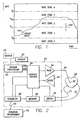
- FIG. 1 shows a typical heart rate of a patient in normal sinus rhythm, line 102, as a function of time.
- time is the horizontal axis
- the heart rate usually expressed in beats per minute (bpm) is the vertical axis.
- the heart rate 102 starts at a relatively low rate (e.g., at an "at rest" rate, which for many patients may be on the order of 70 bpm) at the left of the graph, and then gradually increases as a function of time, as might occur, e.g., if the patient were to begin exercising.
- the heart rate 102 then levels off, near the center of the graph, and eventually begins its return back to the rest rate.
- a first rate threshold reference value is shown in FIG. 1 as the straight line labeled V B .
- the reference rate V B is typically a very low rate, e.g., 50 bpm, and any heart rate that is less than V B thus represents a very slow heart rate, i.e., a bradycardia condition (one form of arrhythmia), for which some sort of treatment is needed.
- a second rate threshold reference value is shown in FIG. 1 as the straight line labeled V TL .
- the reference rate V TL is typically a moderately fast rate, e.g., 135-170 bpm, and any heart rate that is greater than V TL represents a potential ventricular tachycardia condition (another form of arrhythmia) for which a first type of tachycardia therapy may be needed.
- a third rate threshold reference value is shown in FIG. 1 as the straight line labeled V TM .
- the reference rate V TM is typically a fast rate, e.g., 170-220 bpm, and any heart rate that is greater than V TM represents another type of potential ventricular tachycardia condition for which a second type of tachycardia therapy may be needed.
- a fourth rate threshold reference value is shown in FIG. 1 as the straight line V F .
- the reference rate V F is a very fast rate, e.g., greater than 220 bpm, and any heart rate that is greater than V F usually indicates a ventricular fibrillation condition (a serious, life threatening type of arrhythmia) for which appropriate therapy is needed immediately.
- Zone 0 comprises a zone that is bounded at its upper or maximum value by the reference rate V B .
- any rate that is less than the reference rate V B falls within Zone 0 and signifies a possible bradycardia condition.
- Zone 0 may be referred to as a bradycardia rate zone.
- Zone 1 Another rate zone, Zone 1, is bounded at the lower end by the reference rate V B and at the upper end by the reference rate V TL . Any rate that falls within Zone 1 is probably a normal rate, and hence Zone 1 may be referred to as the normal rate zone.
- Zone 2 is bounded at the lower end by the reference rate V TL , and at the upper end by the reference rate V TH . Any heart rate that falls within Zone 2 could signify a tachycardia, and hence Zone 2 may be referred to as a first level tachycardia zone.
- Zone 3 is bounded at the lower end by the reference rate V TH , and at the upper end by the reference rate V F .
- a heart rate that falls within Zone 3 more than likely evidences the existence of a tachycardia.
- Zone 3 may be considered as a second level tachycardia zone.
- Zone 4 A final rate zone, Zone 4, is shown in FIG. 1 as being bounded at the lower end by the reference rate V f , and being unbounded at the upper end.
- a heart rate that falls within Zone 4 signifies the presence of an extremely rapid heart rate, which probably evidences the existence of ventricular fibrillation.
- Zone 4 may be considered as a fibrillation zone.
- rate zones are illustrated in FIG. 1 , such is only exemplary. Any number of rate zones may be used, e.g., two or more, depending upon the particular needs and function of the antitachycardia device that is employed. For example, in a simple antitachycardia detection and treatment device, only two rate zones will typically be used, separated by a single rate threshold reference value, V T . Any heart rate less than the threshold reference V T is considered as falling within the normal rate zone, and any heart rate greater than the threshold reference V T is considered as falling within a tachycardia rate zone. If the heart rate falls within the tachycardia rate zone, then such rate may thus represent a condition for which antitachycardia therapy is required.
- the use of a plurality of rate zones as shown in FIG. 1 advantageously permits a wide variety of different arrhythmia-terminating therapies to be used.
- the particular needs of the patient being treated, as well as the particular type of therapy that has been found to be most effective for a given type of arrhythmia can be considered in tailoring an appropriate therapy for a given patient.
- the medical device simply performs its normal function (which may be providing stimulation pulses on demand at the pacing rate, if the device is a pacemaker; or it may be alerted to detect tachyarrhythmias if the device is an ICD).
- an appropriate antitachycardia therapy may be triggered.
- Such therapy may comprise providing a particular sequence of stimulation pulses, or scanning stimulation pulses in accordance with a prescribed pattern, or providing a low level shock pulse.
- antitachycardia therapies known in the art, see, e.g., U.S. Patent Nos. 3,942,534; 4,442,459; 4,554,920; 4,574,437; 4,574,437; 4,712,556; 4,787,389; 4,788,980; 5,074,308; 5,103,822; and 5,350,401, any of which, or equivalent or other therapies, could be invoked upon entering Zone 2.
- an appropriate therapy for a heart rate falling within Zone 3 may be a different sequence of stimulation pulses, a different or more rapid scanning pattern, double pulsing, a moderate level shock pulse, or the like.
- An appropriate therapy treatment for a heart rate falling within Zone 4 could be one or more high energy defibrillation pulses or shocks.
- an implantable medical device that includes antitachycardia or other arrhythmia-treating features is able to sense the heart rate, classify the heart rate as falling within one or more rate zones, and then act upon the classified heart rate, alone or in combination with other appropriate parameters, to automatically apply an appropriate arrhythmia-terminating therapy when needed.
- the present invention provides for the automatic adjustment of one or more of the detection rate thresholds, i.e., the rate threshold reference signals, used by the implantable medical device.
- the present invention may automatically adjust the threshold reference V TL up or down, as suggested by the arrow 104, as a function of whether it is anticipated that the patient's heart rate will naturally increase or decrease. With such adjustment, the risk is minimized of triggering a Zone 2 therapy when such therapy is not needed.
- the threshold reference V TL is set at 130 bpm. If the patient is at rest, and his or her heart rate suddenly jumps to a value greater than 130 bpm, then a tachycardia condition is probably present, and antitachycardia therapy is appropriate. However, if the patient begins to exercise, e.g., starts to run, then it is quite likely that his or her natural heart rate may reach a value greater than 130 bpm. However, even though the heart rate exceeds the threshold reference V TL , antitachycardia therapy would not be appropriate because an arrhythmia is not present. The present invention thus advantageously adjusts the threshold reference V TL so that it permits the anticipated natural heart rate to occur.
- the invention adjusts the threshold reference V TL up to a rate of, e.g., 160 or 170 bpm once it senses that the patient is exercising, but does not adjust V TL at all if the patient is at rest.
- the antitachycardia therapy is not invoked when the patient exercises and his or her heart rate exceeds 130 bpm, but would be invoked if his or her heart rate exceeds 130 bpm while it appears that the patient is at rest (not exercising).
- the determination as to whether it is anticipated that the heart rate will increase or decrease is made by monitoring a physiologic parameter as sensed through an appropriate sensor.
- the physiologic parameter should be selected to be a parameter that correlates to the patient's natural sinus heart rate, not one that is driven by the heart rate.
- a preferred physiologic parameter suitable for this purpose is physical activity.
- physical activity can be easily sensed using, e.g., a piezoelectric sensor, see e.g., U.S. Patent No. 4,940,053, or a motion sensor, such as is shown in U.S. Patent No. 4,771,780 or 4,846,195.
- physiologic parameters include blood flow, blood pressure, oxygen saturation, and partial pressure of oxygen.
- the sensor which is usually included within or coupled to the medical device, generates a raw sensor signal indicative of the physiologic parameter being monitored.
- the raw sensor signal after suitable processing, may be used directly as the detection rate threshold signal (e.g., as the threshold reference V TL ) or as a control signal from which the detection rate threshold signal is obtained.
- only one of the threshold reference signals (e.g., V TL ) is automatically adjusted as a function of the sensed physiologic parameter, with the other threshold reference signals (e.g., V TH , V F , and V B ) being programmed to a fixed value which does not change until reprogrammed.
- the adjustable threshold reference signal is defined by a prescribed transfer function that relates the value of the raw sensor signal to the threshold reference signal.
- more than one of the threshold reference signals used to define the various rate zones may be automatically adjusted as a function of the sensed physiologic parameter.
- each adjusted threshold reference signal may vary the same as the other reference signals, except for an offset, in which case an entire rate zone, e.g., Zone 2, may move up or down as a function of the sensed physiologic parameter; or each adjusted threshold reference signal may vary differently from the other reference signals, in which case the shape of the rate zone (as defined by its upper and lower boundaries) may change as a function of the sensed physiologic parameter.
- separate sensors may be used for sensing different physiologic parameters, with each physiologic parameter being used to define a different threshold reference signal.
- the implantable medical device comprises a rate-responsive pacemaker, which pacemaker includes its own sensor for sensing if the pacing rate of the pacemaker should change
- the same sensor may advantageously be used by the rate-responsive pacemaker as is used by the present invention for the automatic adjustment of the detection rate threshold.
- the raw sensor signal is separately processed, or otherwise separately handled, so as to allow the raw sensor signal to be used for two separate functions: (1) rate-responsive pacing; and (2) automatic adjustment of the detection rate threshold.
- FIG. 2 A simplified block diagram of the implantable medical device 20 of the present invention is illustrated in FIG. 2 .
- the implantable device 20 is illustrated coupled to a heart 28 by way of an implantable stimulation lead 30.
- the lead 30 is shown as a unipolar lead, having a tip electrode 32. While a single-chamber unipolar system is shown, this is only to illustrates the basic functional blocks. It is understood that one skilled in the art could adapt the present invention to be used in either a dual-chamber device or with bipolar leads.
- Controlling the device 20 is a control system 34.
- the control system 34 could be constructed from dedicated logic and timing circuitry, state machine circuitry, or a microprocessor.
- the control system 34 is coupled to a pacing, or stimulation, channel 24 and a sensing channel 26.
- the pacing channel 24 includes a pulse generator circuitry for generating stimulation pulses of a prescribed pulse width amplitude and rate, as is commonly done in a pacemaker.
- the sensing channel 26 includes amplifiers, filters, and signal conditioners, as needed, in order to properly sense the EGM signals from the heart (e.g., the R-waves and/or P-waves).
- the sensing channel may further be divided into an atrial channel (to sense P-waves) and a ventricular channel (to sense R-waves).
- the control system 34 is also coupled to a shocking channel 35.
- the shocking channel 35 includes defibrillation circuitry for storing and discharging low and high energy shocking pulses to the heart over the leads 31 and 33, as is commonly done in an implantable cardioverter-defibrillator (ICD) device.
- ICD implantable cardioverter-defibrillator
- FIG. 2 it appears from FIG. 2 that the pacing and sensing channels share the same implantable lead 30 and is separate from the shocking leads 31 and 33, it is also known in the art to combine a shocking electrode into the implantable lead 30 for either endocardial placement within the heart, or for epicardial placement on the outside of the heart.
- the memory circuit 34 has control variables and other signals stored therein that are used by the control system 34 as it controls the operation of the device 20.
- the memory circuit 34 may also have EGM data signals stored therein, or other event signals obtained through the sensing channel 26, or data signals obtained by monitoring the status of the device 20.
- the telemetry circuit 38 provides a way of noninvasively interfacing with the memory circuit 36 and the control system 34 from an external (i.e., non-implanted) location using an appropriate external programmer 42.
- a telecommunicative link 43 is established between the programmer 42 and the telemetry circuit 38, as is known in the art. Through this link 43, telemetry circuit 38 and the external programmer 42, a physician or other medical personnel enters appropriate control signals so as to program the device 20 to operate in a prescribed manner. Further, through the link 43, the telemetry circuit 38, and the external programmer 42, EGM data signals and status signals stored in the memory 36, or generated within the control system 34, may be monitored by the physician or other medical personnel.
- the memory circuit 36, telemetry circuit 38, and external programmer 42 may be of conventional design.
- the sensor processing circuit 40 interfaces with a sensor 22, and any other sensors 23, and receives and processes the raw sensor signal(s) therefrom. Such processing includes converting the raw sensor signal(s) to an appropriate threshold reference signal (TRS) that is delivered to the control system 34. The threshold reference signal is then used by the control system 34 to define the boundaries of the appropriate rate zone(s). Further, where the device 20 includes rate-responsive pacing features, and where the sensor 22 is shared so as to provide both rate-responsive and auto detection rate threshold adjustment, the sensor processing circuit 40 also provides a separate sensor indicated rate (SIR) signal. The SIR signal is then used to support the rate-responsive pacing features of the device 20.
- SIR sensor indicated rate
- sensors 22 and any other additional sensors 23 is shown as being outside of the device 20, it is to be understood that the sensors 22 and/or 23 may be included within, or attached to, the device 20.
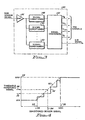
- FIG. 3 a functional block diagram of the sensor processing circuit 40 is shown.
- the circuit 40 includes an amplifier 46 that receives the raw sensor signal from the sensor 22 (FIG. 1). If more than one sensor 22 is used, resulting in more than one raw sensor signal, then additional amplifiers are used for each raw sensor signal, as required. After amplification, the sensor signal is applied to signal conditioning circuits 48-50.
- Each signal conditioner 48-50 conditions or pre-processes the amplified raw signal in a prescribed manner.
- the signal conditioner 48 may comprise a low pass filter that filters out the high frequency components of the amplified raw sensor signal.
- the signal conditioner 49 may comprise a band-bass filter that filters out all of the frequency components of the amplified raw sensor signal except those within a specified bandwidth.
- the signal conditioner 50 may comprise a rectifier and filter circuit that determines the energy content of the raw sensor signal (see, e.g., U.S. Patent No. 4,940,053). As many signal conditioning circuits are used as are needed to properly condition the amplified raw sensor signal(s) for conversion to the threshold reference signals.
- the signal conditioner circuits 48-50 will further normalize the magnitude of the signals that are conditioned thereby.
- the conditioned signal form the conditioner 48 may be normalized to assume a value from 0 to 3 volts.
- the function of amplification provided by the amplifier 46, and the functions of signal conditioning may be performed in a single amplifier/filter circuit.
- the signal conversion circuit 52 which may include analog-to-digital (A/D) conversion, effectively uses a specified transfer function to transfer the conditioned sensor signals to an appropriate threshold reference signal (TRS).
- TRS threshold reference signal
- the output of the A/D converter may also be further normalized, e.g., to assume a value that varies from 0 to 32.
- FIG. 4 Two representative transfer functions used by the signal conversion circuit 52 are graphically shown in FIG. 4 .
- the conditioned sensor signal (the "input signal” to the signal conversion circuit 52) is represented along the horizontal axis of the transfer function representation
- the threshold reference signal(s) (the "output signal” of the signal conversion circuit 52) is represented along the vertical axis of the transfer function representation.
- a first transfer function shown in FIG. 4 is a linear transfer function between minimum and maximum points, and is represented by the dashed line 60.
- the threshold reference signal comprises a MIN value 57 whenever the input signal is less than a LOW value 53; a MAX value 59 whenever the input signal is greater than a HIGH value 55; and a value intermediate the MIN and MAX values whenever the input signal is somewhere between the LOW value 53 and the HIGH value 55.
- the linear relationship is represented by the line 60 for input signal values between the LOW and HIGH values.
- the threshold reference signal is determined by traversing a vertical line from the point 54 to the line 60, and then a horizontal line to the threshold reference signal (TRS) axis, which is a value represented by the point 58.
- TRS threshold reference signal
- the threshold reference signal assumes a value that is defined by the relationship of the input signal to the stair-step line 62. For example, if the input signal is a value represented by the point 54, then the threshold reference signal is determined by drawing a vertical line up from the point 54 to the stair-step line 62, and then a horizontal line over from the stair-step line 62 to the threshold reference signal axis, to the point 56. Thus, as the input signal value changes, the threshold reference signal value also changes, in discrete steps, as defined by the stair-step line 62. Note that the stair-step line 62 is also bounded by upper and lower limits, which (for the function shown in FIG. 4 ) are the same as used for the linear relationship represented by the line 60.
- a separate transfer function is used for each of the threshold reference signals that are used by the device 20.
- a first threshold reference signal function may be used to define V B as a function of the signal V IN obtained from the signal conditioner circuit 48.
- a second threshold reference signal function may be used to define V TL as a function of the signal V IN obtained from the signal conditioner 49; and
- a third threshold reference signal function may be used to define V TH as a function of the signal obtained from the signal conditioner 50.
- the same transfer function may be used to define related threshold reference signals, e.g., the lower and upper limits of a given rate zone.
- one of the threshold reference signals is defined by the specified function, and the other threshold reference signals are then defined in terms of the first threshold reference signal, e.g., to be a value determined by the first threshold reference signal plus an offset value.
- V TL As an example of representative values that may be used relative to defining the threshold reference signal, V TL , assume that the input signal to the signal conversion circuit 52 is digitized and normalized to assume a value of between 0 and 32. Then, representative values for the LOW point 53 may be between 3 and 5, and for the HIGH point 55 between 27 and 29. Representative limits for the MIN and MAX values of V TL may be 120 and 170 bpm, respectively.
- such LOW and HIGH points of the input signal, or MIN and MAX value of the output signal are programmable, as needed, in conventional manner so that the transfer function can be customized to best meet the needs of a particular patient.
- the amplifier 46, signal conditioner circuits 48-50, and signal conversion circuit 52 of the sensor processing circuit 40 shown in FIG. 3 may be realized using analog or digital circuits, e.g., integrated circuits, commercially available from numerous vendors. Alternatively, much of the signal conditioning and signal conversion function may be carried out using a microprocessor that is appropriately programmed to carry out the above-described functions. In such instance, after appropriate amplification and filtering of the raw sensor signal, the amplified and conditioned signal is converted to a digital signal, and made available to the microprocessor as a data input signal. The data input signal is then processed, e.g., normalized and converted to an appropriate threshold reference signal, as described above.
- the signal conversion circuit 52 may also include the appropriate circuitry for generating the sensor indicated rate (SIR) signal used by the rate-responsive circuits of a rate-responsive pacemaker, in the event that rate-responsive pacing is one of the functions provided by the implantable medical device 20.
- SIR-generating circuitry may be of conventional design, e.g., as shown in U.S. Patent No. 4,940,052, or may be as shown in U.S. Application Serial No. 07/844,818, filed 3/2/92, entitled "Method and System for Automatically Adjusting the Sensor Parameters of a Rate-Responsive Pacemaker", assigned to the same assignee as the present application, both of which are incorporated herein by reference.
- the system 34 includes rate detection circuitry 70, threshold detector circuits 72-75, decode logic 76, and pacing control circuitry 78 and antitachycardia therapy control circuitry 80.
- the rate detection circuitry 70 receives the EGM signal (R-waves and/or P-waves) from the sensing channel 26 (FIG. 2) and determines a natural heart rate therefrom.
- the EGM signals are also passed on to the pacing control circuitry 78, as well as the antitachycardia therapy control circuitry 80.
- the heart rate signal is compared to the threshold reference signals using the threshold detection circuits 72-75. That is, the signal is heart rate compared to the threshold reference signal, V B using threshold circuit 72. If the heart rate is greater than V B , then an output signal B of the threshold detector 72 assumes a high value, and if not, the output signal B assumes a low value.
- the heart rate signal is compared to each of the threshold reference signals, V TL V TH , and V F , using threshold circuits 73, 74 and 75, respectively, to generate the output signals TL, TH, and F, respectively. Such output signals, B, TL, TH, and F are then applied to the decode logic 76.
- the decode logic 76 determines the particular rate zone wherein the heart rate signal falls. For example, if all of the threshold output signals B, TL, TH, and F are low, then that indicates the heart rate signal is presently in rate Zone 1 (FIG. 1). If all the threshold output signals are low but the TL signal, then that indicates the heart rate signal is in rate Zone 2. In a similar manner, a determination is made if the heart rate signal falls in any of the other rate zones. Thus, in this manner, an appropriate mode control signal is generated by the decode logic 76 and made available on signal line 77 that indicates the particular rate zone wherein the heart rate signal lies.
- the operation of the threshold circuits 72-75 may be performed on a sampled basis.
- the operation of a given threshold circuit 72-75 is sampled on a periodic basis, e.g., once each cardiac cycle, and the respective output signal, B, TL, TH or F is latched to a low or high value until the next sample time.
- the raw sensor signal applied to the sensor processing circuit 40 may also be sampled, in which case the threshold reference signal's are latched to a given value based on the latest sample taken.
- the mode control signal available on signal line 77 is made available to both the pacing control circuitry 78 and the antitachycardia therapy control circuitry 80.
- an appropriate therapy, or other operation e.g., normal pacing
- the pacing control circuit 78 for example, when invoked by the mode control signal, and when a normal heartbeat is not detected within the prescribed time interval, provides a trigger signal and pulse width and amplitude signals to the pacing channel so that a stimulation pulse of the specified pulse width and amplitude can be generated in the pacing channel.
- the antitachycardia therapy control circuit 80 when invoked by the mode control signal, provides appropriate trigger and energy signals to the pacing channel 24 (which may include a defibrillation output channel) so that a specified type of antitachycardia therapy is applied to the heart.
- the pacing control circuit 78 may be the same as used in conventional implantable pacemakers, as described, e.g., in U.S. Patent Nos. 4,712,555 or 4,940,052.
- the antitachycardia therapy control circuit 80 may be the same as used in conventional ICD devices, as described, e.g., in U.S. Patent Nos. 3,942,534; 4,574,437; or 4,989,602.
- pacing control circuit 78 or antitachycardia therapy control circuit 80 are not important. All that is required is that some sort of control circuit be used that provides the function of pacing or antitachycardia therapy in a prescribed manner.
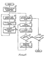
- FIG. 6 a flowchart is shown that illustrates the automatic adjustment of the threshold reference signal (TRS) value, V TL , in accordance with the present invention. It is understood that a similar adjustment of the other threshold reference signal values, V B , V TH , and V F , if used, may also occur.
- each main step is represented as a “box” or “block” (with each block or box having a reference numeral) that is linked to the other steps by one-directional lines, thereby graphically illustrating the "flow” that occurs from one step to the next.
- a first step after enabling the automatic adjustment process is to program the pacing and threshold parameters that are used by the invention and by the other circuits of the implantable medical device (block 82).
- Such parameters include, e.g., the transfer function parameters that define the threshold reference signal, V TL , as a function of the conditioned sensor signal, and the parameters that define the type of pacing or antitachycardia therapy that is to be invoked for each rate zone.
- a first process path relates to the processing of the sensor signal. Such processing includes sampling the raw sensor signal (block 84), processing the sensor signal (block 86), and converting the processed signal to the appropriate threshold reference signal (block 88). All of these sensor signal processing steps are carried out as described above in connection with FIGS. 3 and 4, or equivalent processing steps.
- a second process path relates to the operation of the medical device.
- Such processing includes operating the device in accordance with its programmed mode (block 90). If the device is a pacemaker, for example, its programmed mode may be the DDD mode, or the DDI mode.
- the intrinsic heart rate is sensed (block 92). Also, at an appropriate time, the threshold rate signal, V TL , obtained from the processed sensor signal (block 88), is retrieved or otherwise made available for examination (block 94).
- the heart rate is greater than the threshold rate signal, V TL , (block 96), then that suggests an arrhythmia (e.g., a tachycardia) may be present, so the appropriate antitachycardia therapy may be invoked (block 98).
- the heart rate is again sensed (block 92), the latest value of the threshold reference signal is retrieved (block 94), and the comparison between the heart rate and the threshold reference signal is again made (block 96). This process continues until the arrhythmia (evidenced by the heart rate being greater than the threshold reference signal) is terminated. If the heart rate is less than the threshold reference signal, V TL (block 96), and if the operation of the device is to continue (block 100), then the operation of the device continues pursuant to its programmed mode (block 90), and the process repeats.
- the implantable medical device automatically adjusts its threshold reference signal(s) as a function of the sensor signal(s) that is sensed and processed, and uses such threshold reference signal(s) to determine if an arrhythmia is present for which arrhythmia-terminating therapy is needed. For example, if the sensor signal indicates a high level of physical activity, then the threshold reference signal is accordingly automatically increased by an appropriate amount, thereby assuring that a high or fast natural sinus rate of the heart is not misinterpreted as an arrhythmia for which antitachycardia therapy might otherwise be invoked.
- the present invention provides an implantable antitachycardia medical device, i.e., an implantable pacemaker or an implantable cardioverter-defibrillator (ICD), wherein rate detection circuitry is utilized that minimizes the risk of incorrectly identifying and classifying a fast sinus rate as an arrhythmia for which antitachycardia therapy is needed.
- an implantable antitachycardia medical device i.e., an implantable pacemaker or an implantable cardioverter-defibrillator (ICD)
- rate detection circuitry is utilized that minimizes the risk of incorrectly identifying and classifying a fast sinus rate as an arrhythmia for which antitachycardia therapy is needed.
- the invention provides an implantable antitachycardia device that automatically adjusts its detection rate zone(s), e.g., by automatically adjusting the lower and/or upper limits of such rate zone(s), as a function of a sensed physiologic parameter of the patient, which physiologic parameter provides an indication as to whether the sinus heart rate is expected to change.
- the invention provides an implantable rate-responsive antitachycardia pacemaker wherein a raw signal from a physiologic sensor used with the pacemaker independently provides: (1) the basis for deriving a sensor indicated rate (SIR) signal that sets the pacing rate of the pacemaker, and (2) the basis for adjusting the lower and/or upper limits of a detection rate zone(s) used by the pacemaker to detect when an arrhythmia (for which antitachycardia therapy is needed) is present.
- SIR sensor indicated rate
Description
Claims (19)
- An implantable antitachycardia stimulation device (20) comprising: pulse generating means (24,35) for generating stimulation pulses to a patient's heart (28); sensing means (26) for sensing cardiac activity of the patient's heart; first physiologic sensing means (22) for sensing a physiologic parameter indicative of a normal heart rate, and arranged to generate a first sensor signal representative of the sensed physiologic parameter; and control means (34), coupled to the pulse generating means (24), the sensing means (26), and the first physiological sensing means; wherein the control means (34) is arranged to provide a plurality of prescribed antitachycardia therapies through the pulse generating means (35) and to terminate a sensed cardiac arrhythmia, the control means (34) including: rate detection means arranged to detect the heart rate of the patient based on the cardiac activity sensed through the sensing means (26); threshold means arranged to generate at least two rate zone threshold signals as a function of the first sensor signal including a low rate zone threshold signal and a high rate zone threshold signal, the high rate zone threshold signal being greater than the low rate zone threshold signal; and comparator means arranged to compare the detected heart rate with at least one of the low rate zone threshold signal and the high rate zone threshold signal, to determine when the heart rate exceeds the low rate zone threshold signal or the high rate zone threshold signal, and to indicate that a cardiac arrhythmia is present, wherein the control means provides one of the plurality of prescribed antitachycardia therapies through the pulse generating means appropriate to terminate the indicated cardiac arrhythmia having a detected heart rate exceeding either the low rate zone threshold signal of the high rate zone threshold signal.
- An implantable stimulation device as claimed in Claim 1, characterised by: second physiologic sensing means (23) arranged to sense a second physiologic parameter of the heart (28), and to generate a second sensor signal representative of the second physiologic parameter and rate-responsive pacing means (24) arranged to determine a sensor indicated rate (SIR) signal based on the second sensor signal, and to control the rate of stimulation pulses provided by the pulse generating means according to the sensor indicated rate.
- An implantable stimulation device as claimed in Claim 1, characterised in that the high rate zone threshold signal is a prescribed amount greater than the low rate zone threshold signal.
- An implantable stimulation device, as claimed in Claim 1 or Claim 2, characterised in that the low rate zone threshold signal is generated in accordance with a first function of the first sensor signal, and the high rate zone threshold signal is generated in accordance with a second function of the first sensor signal.
- An implantable stimulation device as claimed in Claim 2, characterised in that the first physiologic sensing means comprises a sensor (22) that senses physical activity of the patient.
- An implantable stimulation device as claimed in Claim 5, characterised in that the second physiological sensing means (23) is adapted to sense a physiologic parameter that is separate from the physiologic parameter sensed by the first physiological sensing means (22).
- An implantable stimulation device as claimed in Claim 5, characterised in that: the first physiologic sensing means (22) and the second physiologic sensing means (23) comprise a single sensor (22) which generates a raw sensor signal indicative of the second physiologic parameter; and the implantable stimulation device further includes sensor processing means (40) arranged to generate the first sensor signal as a first function of the sensed physiologic parameter.
- An implantable stimulation device as claimed in Claim 1, characterised in that the low rate zone threshold signal assumes a minimum value if the first sensor signal is less than a low first sensor signal value, the low rate zone threshold signal assumes a maximum value if the first sensor signal is greater than a high first sensor signal value, and the relationship between the first sensor signal and the low rate zone threshold signal intermediate the low first sensor signal value and the high first sensor signal value is linear; or the low rate zone threshold signal assumes one of a plurality of threshold values intermediate the minimum value and the maximum value of the first sensor signal depending upon which of a respective plurality of first sensor signal reference values intermediate the low and high first sensor signal values is exceeded by the first sensor signal.
- An implantable stimulation device as claimed in Claim 1, characterised in that the control means is arranged to provide a first type of antitachycardia therapy when the detected heart rate exceeds the low rate zone threshold signal and to provide a second type of therapy when the detected heart rate exceeds the high rate zone threshold signal.
- An implantable stimulation device as claimed in Claim 8 or Claim 9, characterised in that the control means comprises: threshold detection means arranged to determine if the heart rate exceeds the first threshold signal, and if so generating a mode control signal; and therapy control means arranged to generate a prescribed sequence of stimulation pulses in response to the mode control signal.
- An implantable stimulation device as claimed in Claim 10, characterised in that the threshold detection means includes means for detecting in which of a plurality of rate zones the heart rate lies.
- An implantable stimulation device as claimed in any of Claims 9 to 12, characterised in that the sensed physiologic parameter comprises physical activity.
- An implantable stimulation device as claimed in any preceding Claim, characterised in that the control means comprises: means for generating a first type of therapy when the detected heart rate exceeds the low rate zone threshold signal and for generating a second type of therapy when the detected heart rate exceeds the high rate zone threshold signal.
- An implantable stimulation device as claimed in any preceding Claim, characterised in that the processing means (40) includes means for defining the first function such that the low rate zone threshold signal assumes a minimum value if the sensor signal is less than a low sensor signal value, and the low rate zone threshold signal assumes maximum value if the sensor signal is greater than a high sensor signal value.
- An implantable stimulation device as claimed in Claim 14, characterised in that the processing means (40) comprises means for defining the first function as being a linear relationship between the sensor signal and the low rate zone threshold signal intermediate the low sensor signal value and the high sensor signal value.
- An implantable stimulation device as claimed in Claim 14, characterised in that the processing means (40) comprises means of defining the first function such that the low rate zone threshold signal assumes one of a plurality of threshold values intermediate the minimum value and the maximum value depending upon which of a respective plurality of sensor signal reference values intermediate the low and high sensor signal values is exceeded by the sensor signal.
- An implantable stimulation device as claimed in any preceding Claim, characterised in that the control means comprises: threshold detection means arranged to determine if the heart rate exceeds the low rate zone threshold signal, and if so generating a mode control signal; and therapy control means arranged to generate a prescribed sequence of stimulation pulses in response to the mode control signal.
- An implantable stimulation device as claimed in Claim 17, characterised in that the threshold detection means includes means for detecting in which of a plurality of rate zones the heart rate lies.
- An implantable antitachycardia therapy device as claimed in any preceding Claim, characterised in that the sensed physiologic parameter comprises physical activity.
Applications Claiming Priority (2)
| Application Number | Priority Date | Filing Date | Title |
|---|---|---|---|
| US08/449,970 US5882352A (en) | 1995-05-25 | 1995-05-25 | Automatic adjustment of detection rate threshold in an implantable antitachycardia therapy device |
| US449970 | 1995-05-25 |
Publications (3)
| Publication Number | Publication Date |
|---|---|
| EP0744190A2 EP0744190A2 (en) | 1996-11-27 |
| EP0744190A3 EP0744190A3 (en) | 1998-06-17 |
| EP0744190B1 true EP0744190B1 (en) | 2004-12-01 |
Family
ID=23786216
Family Applications (1)
| Application Number | Title | Priority Date | Filing Date |
|---|---|---|---|
| EP96303751A Expired - Lifetime EP0744190B1 (en) | 1995-05-25 | 1996-05-24 | Implantable antitachycardia stimulation device |
Country Status (4)
| Country | Link |
|---|---|
| US (1) | US5882352A (en) |
| EP (1) | EP0744190B1 (en) |
| JP (1) | JPH09117518A (en) |
| DE (1) | DE69633957T2 (en) |
Families Citing this family (57)
| Publication number | Priority date | Publication date | Assignee | Title |
|---|---|---|---|---|
| US5702427A (en) * | 1996-03-28 | 1997-12-30 | Medtronic, Inc. | Verification of capture using pressure waves transmitted through a pacing lead |
| US5978707A (en) | 1997-04-30 | 1999-11-02 | Cardiac Pacemakers, Inc. | Apparatus and method for treating ventricular tachyarrhythmias |
| US6038476A (en) * | 1998-06-12 | 2000-03-14 | Pacesetter, Inc. | System and method for analyzing the efficacy of cardiac stimulation therapy |
| FR2794656B1 (en) * | 1999-06-11 | 2001-07-27 | Ela Medical Sa | ACTIVE IMPLANTABLE MEDICAL DEVICE, IN PARTICULAR A CARDIAC STIMULATOR, A DEFIBRILLATOR OR A MULTISITE-TYPE CARDIOVERTER, COMPRISING RESYNCHRONIZED STIMULATION MEANS FOR THE TREATMENT OF HEART FAILURE |
| US6230055B1 (en) | 1999-08-20 | 2001-05-08 | Cardiac Pacemakers, Inc. | Method and apparatus for adaptive tachycardia and fibrillation discrimination |
| US6493579B1 (en) | 1999-08-20 | 2002-12-10 | Cardiac Pacemakers, Inc. | System and method for detection enhancement programming |
| US6368284B1 (en) * | 1999-11-16 | 2002-04-09 | Cardiac Intelligence Corporation | Automated collection and analysis patient care system and method for diagnosing and monitoring myocardial ischemia and outcomes thereof |
| US6456871B1 (en) * | 1999-12-01 | 2002-09-24 | Cardiac Pacemakers, Inc. | System and method of classifying tachyarrhythmia episodes as associated or disassociated |
| US6445949B1 (en) * | 2000-01-05 | 2002-09-03 | Pacesetter, Inc. | Implantable cardioversion device with a self-adjusting threshold for therapy selection |
| US6522925B1 (en) | 2000-05-13 | 2003-02-18 | Cardiac Pacemakers, Inc. | System and method for detection enhancement programming |
| US7039461B1 (en) | 2000-05-13 | 2006-05-02 | Cardiac Pacemakers, Inc. | Cardiac pacing system for prevention of ventricular fibrillation and ventricular tachycardia episode |
| US6751502B2 (en) | 2001-03-14 | 2004-06-15 | Cardiac Pacemakers, Inc. | Cardiac rhythm management system with defibrillation threshold prediction |
| US7386344B2 (en) * | 2004-08-11 | 2008-06-10 | Cardiac Pacemakers, Inc. | Pacer with combined defibrillator tailored for bradycardia patients |
| US6748269B2 (en) | 2001-10-17 | 2004-06-08 | Cardiac Pacemakers, Inc. | Algorithm for discrimination of 1:1 tachycardias |
| US7330757B2 (en) * | 2001-11-21 | 2008-02-12 | Cameron Health, Inc. | Method for discriminating between ventricular and supraventricular arrhythmias |
| US6862476B2 (en) * | 2002-02-20 | 2005-03-01 | Pacesetter, Inc. | Implantable cardiac stimulation device having automatic sensitivity control and method |
| FR2844456B1 (en) * | 2002-09-16 | 2004-10-22 | Ela Medical Sa | IMPLANTABLE ACTIVE MEDICAL DEVICE OF THE DEFIBRILLATOR, CARDIOVERTER AND / OR ANTITACHYCARDIAL STIMULATOR TYPE, WITH HIGH HIGH FREQUENCY OF ANTIBRADYCARDIAL STIMULATION |
| EP1558335A1 (en) * | 2002-09-19 | 2005-08-03 | Biotronik GmbH & Co. KG | Device with redetection therapy threshold |
| US7226422B2 (en) | 2002-10-09 | 2007-06-05 | Cardiac Pacemakers, Inc. | Detection of congestion from monitoring patient response to a recumbent position |
| US7120491B1 (en) * | 2003-03-12 | 2006-10-10 | Pacesetter, Inc. | Implantable cardioversion device with a self-adjusting threshold for therapy selection |
| US7177683B2 (en) * | 2003-04-30 | 2007-02-13 | Medtronic, Inc. | History-dependent pacing interval determination for antitachycardia pacing |
| CN101912667B (en) * | 2003-05-29 | 2014-04-02 | 卡梅伦保健公司 | Method for discriminating between ventricular and supraventricular arrhythmias |
| US7200440B2 (en) | 2003-07-02 | 2007-04-03 | Cardiac Pacemakers, Inc. | Cardiac cycle synchronized sampling of impedance signal |
| US7684861B2 (en) | 2003-11-13 | 2010-03-23 | Cardiac Pacemakers, Inc. | Implantable cardiac monitor upgradeable to pacemaker or cardiac resynchronization device |
| US7299086B2 (en) | 2004-03-05 | 2007-11-20 | Cardiac Pacemakers, Inc. | Wireless ECG in implantable devices |
| US7616994B2 (en) | 2004-05-24 | 2009-11-10 | Cardiac Pacemakers, Inc. | Fast post-antitachycardia pacing redetection algorithm |
| US7974685B2 (en) | 2004-07-22 | 2011-07-05 | Cardiac Pacemakers, Inc. | Systems, devices, and methods for tachyarrhythmia discrimination or therapy decisions |
| US7228176B2 (en) | 2004-07-22 | 2007-06-05 | Cardiac Pacemakers, Inc. | Systems, devices, and methods for tachyarrhythmia discrimination or therapy decisions |
| US7387610B2 (en) | 2004-08-19 | 2008-06-17 | Cardiac Pacemakers, Inc. | Thoracic impedance detection with blood resistivity compensation |
| US7212849B2 (en) | 2004-10-28 | 2007-05-01 | Cardiac Pacemakers, Inc. | Methods and apparatuses for arrhythmia detection and classification using wireless ECG |
| US7603170B2 (en) * | 2005-04-26 | 2009-10-13 | Cardiac Pacemakers, Inc. | Calibration of impedance monitoring of respiratory volumes using thoracic D.C. impedance |
| US7881786B2 (en) * | 2005-04-29 | 2011-02-01 | Medtronic, Inc. | Suppression of high rate pacing for reducing myocardial ischemic irritability |
| US7907997B2 (en) * | 2005-05-11 | 2011-03-15 | Cardiac Pacemakers, Inc. | Enhancements to the detection of pulmonary edema when using transthoracic impedance |
| US9089275B2 (en) * | 2005-05-11 | 2015-07-28 | Cardiac Pacemakers, Inc. | Sensitivity and specificity of pulmonary edema detection when using transthoracic impedance |
| US20070012213A1 (en) * | 2005-07-12 | 2007-01-18 | Sheaffer Clifford G | Shot pattern control wad structure for shotshell |
| US7927284B2 (en) * | 2005-09-16 | 2011-04-19 | Cardiac Pacemakers, Inc. | Quantifying hemodynamic response to drug therapy using implantable sensor |
| US20070073352A1 (en) * | 2005-09-28 | 2007-03-29 | Euler David E | Method and apparatus for regulating a cardiac stimulation therapy |
| US7582061B2 (en) * | 2005-12-22 | 2009-09-01 | Cardiac Pacemakers, Inc. | Method and apparatus for morphology-based arrhythmia classification using cardiac and other physiological signals |
| US8391978B2 (en) * | 2006-04-26 | 2013-03-05 | Medtronic, Inc. | Method and apparatus for adjusting sensitivity using intracardiac pressure data |
| US8000780B2 (en) | 2006-06-27 | 2011-08-16 | Cardiac Pacemakers, Inc. | Detection of myocardial ischemia from the time sequence of implanted sensor measurements |
| US7580741B2 (en) | 2006-08-18 | 2009-08-25 | Cardiac Pacemakers, Inc. | Method and device for determination of arrhythmia rate zone thresholds using a probability function |
| US7941208B2 (en) | 2006-11-29 | 2011-05-10 | Cardiac Pacemakers, Inc. | Therapy delivery for identified tachyarrhythmia episode types |
| US8271080B2 (en) | 2007-05-23 | 2012-09-18 | Cardiac Pacemakers, Inc. | Decongestive therapy titration for heart failure patients using implantable sensor |
| EP2222223B1 (en) * | 2007-08-16 | 2016-10-12 | Medtronic Inc. | Systems for managing heart rate dependent conditions |
| US7840265B2 (en) | 2007-12-18 | 2010-11-23 | Cardiac Pacemakers, Inc. | Anti-tachyarrhythmia system with selectively activated detection enhancements |
| EP2299907B1 (en) * | 2008-06-02 | 2015-02-11 | Medtronic, Inc. | Discrimination of ventricular tachycardia from supraventricular tachycardia |
| US8175706B2 (en) * | 2008-09-04 | 2012-05-08 | Medtronic, Inc. | Overlapping pacing and tachyarrhythmia detection zones |
| EP2362747A1 (en) * | 2008-09-23 | 2011-09-07 | Cardiac Pacemakers, Inc. | Method and apparatus for organ specific inflammation monitoring |
| WO2010118033A1 (en) * | 2009-04-07 | 2010-10-14 | Cardiac Pacemakers, Inc. | Apparatus for organ-specific inflammation therapy |
| US8473039B2 (en) * | 2010-04-15 | 2013-06-25 | LifeWatch Inc. | System and a method for cardiac monitoring |
| US9314205B2 (en) | 2011-04-28 | 2016-04-19 | Medtronic, Inc. | Measurement of cardiac cycle length and pressure metrics from pulmonary arterial pressure |
| WO2015106015A1 (en) | 2014-01-10 | 2015-07-16 | Cardiac Pacemakers, Inc. | Systems and methods for detecting cardiac arrhythmias |
| US10449361B2 (en) | 2014-01-10 | 2019-10-22 | Cardiac Pacemakers, Inc. | Systems and methods for treating cardiac arrhythmias |
| US10463866B2 (en) | 2014-07-11 | 2019-11-05 | Cardiac Pacemakers, Inc. | Systems and methods for treating cardiac arrhythmias |
| US9656091B2 (en) * | 2014-07-11 | 2017-05-23 | Cardiac Pacemakers, Inc. | Power saving communication for medical devices |
| WO2016126613A1 (en) | 2015-02-06 | 2016-08-11 | Cardiac Pacemakers, Inc. | Systems and methods for treating cardiac arrhythmias |
| US10758737B2 (en) | 2016-09-21 | 2020-09-01 | Cardiac Pacemakers, Inc. | Using sensor data from an intracardially implanted medical device to influence operation of an extracardially implantable cardioverter |
Family Cites Families (20)
| Publication number | Priority date | Publication date | Assignee | Title |
|---|---|---|---|---|
| GB1493353A (en) * | 1973-11-21 | 1977-11-30 | Devices Implants Ltd | Device for terminating tachycardia |
| US4422459A (en) * | 1980-11-18 | 1983-12-27 | University Patents, Inc. | Electrocardiographic means and method for detecting potential ventricular tachycardia |
| US4428378A (en) * | 1981-11-19 | 1984-01-31 | Medtronic, Inc. | Rate adaptive pacer |
| SE8107269L (en) * | 1981-12-04 | 1983-06-05 | Siemens Elema Ab | DEVICE FOR ENDING A TAKYCARDI |
| US4712556A (en) * | 1982-11-22 | 1987-12-15 | Intermedics, Inc. | Pacemaker and method for ventricular rate limit operation and termination of pacemaker mediated tachycardia |
| US4554920A (en) * | 1982-11-22 | 1985-11-26 | Intermedics, Inc. | Microprocessor controlled cardiac pacemaker and method for avoiding pacer sustained tachycardia |
| US4576183A (en) * | 1983-09-21 | 1986-03-18 | Gianni Plicchi | Electronic circuit for monitoring respiratory parameter for controlling operation of implantable medical device |
| US4686988A (en) * | 1984-10-19 | 1987-08-18 | Sholder Jason A | Pacemaker system and method for measuring and monitoring cardiac activity and for determining and maintaining capture |
| US4788980A (en) * | 1986-07-18 | 1988-12-06 | Siemens-Pacesetter, Inc. | Pacemaker having PVC response and PMT terminating features |
| US4771780A (en) * | 1987-01-15 | 1988-09-20 | Siemens-Pacesetter, Inc. | Rate-responsive pacemaker having digital motion sensor |
| DE3709073A1 (en) * | 1987-03-19 | 1988-09-29 | Alt Eckhard | IMPLANTABLE MEDICAL DEVICE |
| US4787389A (en) * | 1987-07-16 | 1988-11-29 | Tnc Medical Devices Pte. Ltd. | Using an implantable antitachycardia defibrillator circuit |
| US4940052A (en) * | 1989-01-25 | 1990-07-10 | Siemens-Pacesetter, Inc. | Microprocessor controlled rate-responsive pacemaker having automatic rate response threshold adjustment |
| US4940053A (en) * | 1989-01-25 | 1990-07-10 | Siemens-Pacesetter, Inc. | Energy controlled rate-responsive pacemaker having automatically adjustable control parameters |
| US4989602A (en) * | 1989-04-12 | 1991-02-05 | Siemens-Pacesetter, Inc. | Programmable automatic implantable cardioverter/defibrillator and pacemaker system |
| US5103822A (en) * | 1990-04-03 | 1992-04-14 | Siemens-Pacesetter, Inc. | Pacing system for termination of cardiac arrhythmias utilizing scanning techniques |
| US5074308A (en) * | 1990-09-26 | 1991-12-24 | Siemens-Pacesetter, Inc. | System and method for recognizing pacemaker-mediated tachycardia |
| US5312443A (en) * | 1992-02-20 | 1994-05-17 | Angeion Corporation | Arrhythmia-detection criteria process for a cardioverter/defibrillator |
| US5370667A (en) * | 1992-04-03 | 1994-12-06 | Intermedics, Inc. | Device and method for automatically adjusting tachycardia recognition criteria based on detected parameter |
| JPH07504596A (en) * | 1992-06-30 | 1995-05-25 | メドトロニック インコーポレーテッド | Electrical medical stimulators and electrical stimulation methods |
-
1995
- 1995-05-25 US US08/449,970 patent/US5882352A/en not_active Expired - Lifetime
-
1996
- 1996-05-22 JP JP8149737A patent/JPH09117518A/en active Pending
- 1996-05-24 DE DE69633957T patent/DE69633957T2/en not_active Expired - Lifetime
- 1996-05-24 EP EP96303751A patent/EP0744190B1/en not_active Expired - Lifetime
Also Published As
| Publication number | Publication date |
|---|---|
| DE69633957D1 (en) | 2005-01-05 |
| US5882352A (en) | 1999-03-16 |
| JPH09117518A (en) | 1997-05-06 |
| EP0744190A2 (en) | 1996-11-27 |
| DE69633957T2 (en) | 2005-11-03 |
| EP0744190A3 (en) | 1998-06-17 |
Similar Documents
| Publication | Publication Date | Title |
|---|---|---|
| EP0744190B1 (en) | Implantable antitachycardia stimulation device | |
| US9031649B2 (en) | Reducing inappropriate delivery of therapy for suspected non-lethal arrhythmias | |
| EP1622679B1 (en) | System for use of an accelerometer signal to augment ventricular arrhythmia detection | |
| US4880004A (en) | Implantable cardiac stimulator with automatic gain control and bandpass filtering in feedback loop | |
| US6567691B1 (en) | Method and apparatus diagnosis and treatment of arrhythias | |
| EP0902707B1 (en) | Prioritized rule based apparatus for diagnosis and treatment of arrhythmias | |
| US6978177B1 (en) | Method and apparatus for using atrial discrimination algorithms to determine optimal pacing therapy and therapy timing | |
| CN105324076B (en) | Staged cardiac rhythm detection system and method | |
| EP1899005B1 (en) | Suppression of high rate pacing for reducing myocardial ischemic irritability | |
| US8140156B2 (en) | Heart sound sensing to reduce inappropriate tachyarrhythmia therapy | |
| US7813791B1 (en) | Systems and methods for employing an FFT to distinguish R-waves from T-waves using an implantable medical device | |
| JP4865713B2 (en) | ATP treatment for tachyarrhythmia | |
| US6249701B1 (en) | Implantable device with automatic sensing adjustment | |
| US8437849B2 (en) | Method and apparatus for atrial pacing during tachyarrhythmia | |
| US20030074028A1 (en) | Arrangement for predicting tacharrhythmia |
Legal Events
| Date | Code | Title | Description |
|---|---|---|---|
| PUAI | Public reference made under article 153(3) epc to a published international application that has entered the european phase |
Free format text: ORIGINAL CODE: 0009012 |
|
| AK | Designated contracting states |
Kind code of ref document: A2 Designated state(s): DE ES FR GB IT NL |
|
| PUAL | Search report despatched |
Free format text: ORIGINAL CODE: 0009013 |
|
| AK | Designated contracting states |
Kind code of ref document: A3 Designated state(s): DE ES FR GB IT NL |
|
| 17P | Request for examination filed |
Effective date: 19981210 |
|
| 17Q | First examination report despatched |
Effective date: 20031118 |
|
| GRAP | Despatch of communication of intention to grant a patent |
Free format text: ORIGINAL CODE: EPIDOSNIGR1 |
|
| GRAS | Grant fee paid |
Free format text: ORIGINAL CODE: EPIDOSNIGR3 |
|
| GRAA | (expected) grant |
Free format text: ORIGINAL CODE: 0009210 |
|
| AK | Designated contracting states |
Kind code of ref document: B1 Designated state(s): DE ES FR GB IT NL |
|
| PG25 | Lapsed in a contracting state [announced via postgrant information from national office to epo] |
Ref country code: NL Free format text: LAPSE BECAUSE OF FAILURE TO SUBMIT A TRANSLATION OF THE DESCRIPTION OR TO PAY THE FEE WITHIN THE PRESCRIBED TIME-LIMIT Effective date: 20041201 Ref country code: ES Free format text: LAPSE BECAUSE OF FAILURE TO SUBMIT A TRANSLATION OF THE DESCRIPTION OR TO PAY THE FEE WITHIN THE PRESCRIBED TIME-LIMIT Effective date: 20041201 |
|
| REG | Reference to a national code |
Ref country code: GB Ref legal event code: FG4D |
|
| REF | Corresponds to: |
Ref document number: 69633957 Country of ref document: DE Date of ref document: 20050105 Kind code of ref document: P |
|
| PG25 | Lapsed in a contracting state [announced via postgrant information from national office to epo] |
Ref country code: GB Free format text: LAPSE BECAUSE OF NON-PAYMENT OF DUE FEES Effective date: 20050524 |
|
| NLV1 | Nl: lapsed or annulled due to failure to fulfill the requirements of art. 29p and 29m of the patents act | ||
| PLBE | No opposition filed within time limit |
Free format text: ORIGINAL CODE: 0009261 |
|
| STAA | Information on the status of an ep patent application or granted ep patent |
Free format text: STATUS: NO OPPOSITION FILED WITHIN TIME LIMIT |
|
| ET | Fr: translation filed | ||
| 26N | No opposition filed |
Effective date: 20050902 |
|
| GBPC | Gb: european patent ceased through non-payment of renewal fee |
Effective date: 20050524 |
|
| PGFP | Annual fee paid to national office [announced via postgrant information from national office to epo] |
Ref country code: FR Payment date: 20060517 Year of fee payment: 11 |
|
| REG | Reference to a national code |
Ref country code: FR Ref legal event code: ST Effective date: 20080131 |
|
| PG25 | Lapsed in a contracting state [announced via postgrant information from national office to epo] |
Ref country code: FR Free format text: LAPSE BECAUSE OF NON-PAYMENT OF DUE FEES Effective date: 20070531 |
|
| PGFP | Annual fee paid to national office [announced via postgrant information from national office to epo] |
Ref country code: IT Payment date: 20080528 Year of fee payment: 13 |
|
| PG25 | Lapsed in a contracting state [announced via postgrant information from national office to epo] |
Ref country code: IT Free format text: LAPSE BECAUSE OF NON-PAYMENT OF DUE FEES Effective date: 20090524 |
|
| PGFP | Annual fee paid to national office [announced via postgrant information from national office to epo] |
Ref country code: DE Payment date: 20110527 Year of fee payment: 16 |
|
| REG | Reference to a national code |
Ref country code: DE Ref legal event code: R119 Ref document number: 69633957 Country of ref document: DE Effective date: 20121201 |
|
| PG25 | Lapsed in a contracting state [announced via postgrant information from national office to epo] |
Ref country code: DE Free format text: LAPSE BECAUSE OF NON-PAYMENT OF DUE FEES Effective date: 20121201 |