EP0744526A1 - Method for controlling a drilling tool - Google Patents
Method for controlling a drilling tool Download PDFInfo
- Publication number
- EP0744526A1 EP0744526A1 EP95107954A EP95107954A EP0744526A1 EP 0744526 A1 EP0744526 A1 EP 0744526A1 EP 95107954 A EP95107954 A EP 95107954A EP 95107954 A EP95107954 A EP 95107954A EP 0744526 A1 EP0744526 A1 EP 0744526A1
- Authority
- EP
- European Patent Office
- Prior art keywords
- tool
- drilling
- internal control
- actuators
- control loop
- Prior art date
- Legal status (The legal status is an assumption and is not a legal conclusion. Google has not performed a legal analysis and makes no representation as to the accuracy of the status listed.)
- Granted
Links
Images


Classifications
-
- E—FIXED CONSTRUCTIONS
- E21—EARTH DRILLING; MINING
- E21B—EARTH DRILLING, e.g. DEEP DRILLING; OBTAINING OIL, GAS, WATER, SOLUBLE OR MELTABLE MATERIALS OR A SLURRY OF MINERALS FROM WELLS
- E21B44/00—Automatic control systems specially adapted for drilling operations, i.e. self-operating systems which function to carry out or modify a drilling operation without intervention of a human operator, e.g. computer-controlled drilling systems; Systems specially adapted for monitoring a plurality of drilling variables or conditions
- E21B44/005—Below-ground automatic control systems
-
- E—FIXED CONSTRUCTIONS
- E21—EARTH DRILLING; MINING
- E21B—EARTH DRILLING, e.g. DEEP DRILLING; OBTAINING OIL, GAS, WATER, SOLUBLE OR MELTABLE MATERIALS OR A SLURRY OF MINERALS FROM WELLS
- E21B44/00—Automatic control systems specially adapted for drilling operations, i.e. self-operating systems which function to carry out or modify a drilling operation without intervention of a human operator, e.g. computer-controlled drilling systems; Systems specially adapted for monitoring a plurality of drilling variables or conditions
-
- E—FIXED CONSTRUCTIONS
- E21—EARTH DRILLING; MINING
- E21B—EARTH DRILLING, e.g. DEEP DRILLING; OBTAINING OIL, GAS, WATER, SOLUBLE OR MELTABLE MATERIALS OR A SLURRY OF MINERALS FROM WELLS
- E21B47/00—Survey of boreholes or wells
- E21B47/02—Determining slope or direction
- E21B47/022—Determining slope or direction of the borehole, e.g. using geomagnetism
-
- E—FIXED CONSTRUCTIONS
- E21—EARTH DRILLING; MINING
- E21B—EARTH DRILLING, e.g. DEEP DRILLING; OBTAINING OIL, GAS, WATER, SOLUBLE OR MELTABLE MATERIALS OR A SLURRY OF MINERALS FROM WELLS
- E21B7/00—Special methods or apparatus for drilling
- E21B7/04—Directional drilling
- E21B7/06—Deflecting the direction of boreholes
- E21B7/062—Deflecting the direction of boreholes the tool shaft rotating inside a non-rotating guide travelling with the shaft
Definitions
- the invention relates to a method for controlling a drilling tool, which can be directed at least by a group of controllable actuators assigned to the tool and distributed over the tool circumference, during drilling operation in underground formations according to the preamble of claim 1.
- the setpoint values for the course of the drilling tool between a starting point and a target point are given to the in-tool control loop, which are compared by the in-tool control loop with actual course values, which are determined by the in-tool measurement sensor for the direction of the drilling tool and its depth.
- the tool-internal control circuit calculates correction data for the drilling direction that are suitable for tracing the drilling tool back to its target course.
- the tool-internal control loop is in data exchange with an external control loop, which evaluates the data received from underground and makes it possible to provide operating instructions or new data to the tool-internal control loop, for example for a changed course or the tool depth measured during the day. Until new operating instructions are received or Course data and then the internal control loop determines the course of the drilling tool until the target is reached.
- the invention is concerned with the problem of creating a method of the type mentioned which enables precise surface tool guidance.
- the invention solves the problem by means of a method having the features of claim 1. With regard to further essential configurations, reference is made to claims 2 to 4.
- the method according to the invention assigns the external control loop the main control function which the latter can automatically perform after evaluating the data received during the day.
- the external control loop assigns the external control function which the latter can automatically perform after evaluating the data received during the day.
- there is the possibility of individual influence on the tool course by an operator following the action underground who, like with automatic course specification, can carry out the tool control solely by specifying a single control vector.
- This enables extremely cautious, quickly correctable course determinations, which enables drilling a borehole with a smooth curve that is largely free of kinks and jags.
- This is particularly important in the case of bores with a far-reaching horizontal course, the range of which is decisively influenced by the drill string friction in the borehole, because the more irregular the course of the borehole, the greater it is.
- the method according to the invention therefore favors the creation of horizontal bores with an extended range.
- Fig. 1 illustrates schematically a drilling rig 1 for sinking boreholes 2 into underground rock formations with the aid of a drilling tool 3 at the front end of a drill string 4, the progressive construction and drive of which is generally known and requires no further explanation.
- a non-rotating drilling string can also be used with a drilling tool, the drill bit of which is driven by an underground motor.
- the above-ground operation center is shown directly adjacent to the drilling rig 1 in the example shown and is designated by 5, but can also be set up at any distance from the drilling rig 1, provided that a suitable transmission of drilling operating data is ensured, which in the example shown is carried out by an electrical device Line connection 6 is made.
- the tool 3 comprises a housing 8 screwed to the drill string 4 at 7, which is screwed at 9 with a retracted extension 10, which is connected at its lower end via a screw connection 11 to a drill bit 12.
- the housing 8 and its extension 9 have a central flow channel 13 for the passage of a flushing agent which flows down the drill string 4, exits the drill bit 12 into the borehole 2 and in the annular space between the wall of the borehole 2 and the tool 3 or the drill string 4 flows back to the drilling system 1, where it reaches a mud tank, not shown, from which it is conveyed into the drill string 4 by means of a mud pump.
- a generator 16 for the power supply to the electrical consumers on the tool side, which can be driven by a turbine 17, which is only indicated schematically and is acted upon by the flushing agent flow.
- Generator 16 and turbine 17 can form part of an underground information receiver, the receiving and further processing part of which is indicated schematically at 18.
- an information transmitter indicated at 19, for example a pulse transmitter acting on the flushing agent flow, with the aid of which tool-internal data present during the day can be transmitted to an above-ground information receiver, which is only schematically illustrated at 20.
- the above-ground information provider for above-ground data to be transmitted to the control system of the drilling tool 3 is also only indicated schematically in FIG. 1 and designated by 21.
- a sleeve-shaped housing part 25 is rotatably supported via bearings 23, which assumes a non-rotating position in the borehole 2 during operation, while the drill string 4, housing 8, extension 10 and drill bit 12 about their central axis as a result of the surface drive of drill string 4 rotate.
- the housing part 25 is provided with three actuators in the form of ribs 26, 27, 28, which have a shape similar to a stabilizer rib and are each supported on the housing part 25 such that they can be folded about an axis 29.
- the ribs 26, 27, 28 can be transferred individually and independently of one another by means of a pressure medium drive 30, 31, 32 from the folded starting position shown in FIG. 4 to a more or less extended operating position, in which they are on the wall of the borehole 2 apply and exert an individually definable pressure force on them.
- a hydraulic pump 33 is provided in the housing part 25, which acts on the pressure medium drives 30, 31, 32 with hydraulic medium via hydraulic lines 34.
- the hydraulic pump 33 can be driven by means of an electric motor which is generated by the generator 16 or is powered by a battery supplied by this.
- actuators instead of three actuators, which are sufficient for precise alignment of the drilling tool 3, more than three, for example four or five, actuators can also be provided.
- an electronic control system is accommodated in the housing part 25, which is indicated at 35 and comprises sensors 36 for recording required measurement values and an evaluation and arithmetic unit 37 which forms part of an internal control loop.
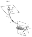
- the measured values required by the method for tool control according to the invention include the current drilling direction 45, which, due to the angle 43 of the tool of the tool axes 58, forms a reference direction, for example the magnetic north direction 40 (FIG. 2) (azimuth) and the Angle 44 of tool axis 58 to a further reference direction, preferably the direction of gravitational acceleration 41, can be defined.
- These measured values are determined by sensors 36 on the tool side.
- the required measured values also include the rotational angle position of the drilling tool 3 in the borehole 2 with respect to a reference plane, preferably a plane 53 which intersects the zero point 50 of a plane coordinate system 51 which is permanently assigned to the drilling tool 3 and coincides with the direction of the acceleration due to gravity and which is the top of the tool 3 intersects in an upper culmination line defined by the culmination points 52.
- the current angle of rotation position of the drilling tool 3 results as the angle 54 between the reference plane 53 defined by the direction of gravity and the reference plane 55 fixed to the tool, which coincides with the ordinate of the coordinate system fixed to the tool. so that complete information about the alignment and orientation of the drilling tool 3 is given.
- the force with which the ribs 26, 27, 28 press against the wall of the borehole 2 is also determined. This can be done by means of pressure sensors or derived from the control valve settings for the pressure medium drives 30, 31, 32. A resulting force is determined from the individual forces, which force is defined according to magnitude and direction and forms a control vector 56.
- the direction of the control vector 56 intersecting the zero point of the fixed coordinate system 51 and the tool axis 58 is defined as the angle 57, which the control vector 56 forms with the reference plane 53.
- the sensors 36 belonging to the tool-internal control circuit 60 provide the measured values for the current drilling direction of the drilling tool 3, the current setting of the actuators 26, 27, 28 and the rotation angle orientation (Angle 54) of the drilling tool 3 determined.
- This data is transferred to a computing part 61 of the tool-internal control circuit 60, which compensates for deviations of the reference plane 55 fixed to the tool from the reference plane 53 specified in the direction of acceleration due to gravity, and determines the direction (angle 57) and amount of the current control vector 56.
- the entire and processed data are transferred via a data transmission system 62, which includes, for example, the information provider 19 and the information receiver 21, to an external control circuit 70, in which this data is processed in a manner to be described.
- a data transmission system 62 which includes, for example, the information provider 19 and the information receiver 21, to an external control circuit 70, in which this data is processed in a manner to be described.
- the compensated actual control vector values supplied by the arithmetic element 61 become one in the tool-internal control loop
- Comparison part 63 of the control circuit 60 is compared with predetermined, stored control vector target values and the result value is fed to the evaluation and arithmetic unit 37 of the tool-internal control system 35, which, if necessary, corrects the setting of the actuators 26, 27, 28.
- the actual values of the current drilling direction of the drilling tool 3 delivered by the tool-internal control circuit 60 are compared with directional setpoints stored above ground in a computer 72, and the current geological position of the drilling tool 3 is determined, taking into account the tool depth determined above ground by a measuring device 71. If there are deviations from the specified course that make a correction necessary, suitable new setpoints for the control vector 56 can be automatically determined and via a control unit 73 in which the data e.g. are encoded as a digital sequence of signals and are transferred to the tool-internal control circuit 60 via a data transmission system 74.
- the data transmitted from the computer 72 to a monitoring unit 75 can give an operator cause to implement a control vector 56 that he has selected, which can be done by a corresponding input at 76.
- a personal control system can be used to predefine a course for the drilling tool 3 which moves outside the possibilities specified in the program. This can be useful not only for the purpose of optimizing a course correction, but also if a course change is indicated on the basis of other data found during the day, for example about the type of pierced formations.
- the external control circuit 70 can switch to the tool-internal control circuit 60
- Direction hold command are transmitted, in which case the current actual direction values of the drilling tool 3 are stored in a data memory of the tool-internal control circuit 60, which can be assigned to the comparison part 63, as a setpoint value and then continuously compared with further determined actual direction values.
- Control variables based on such a direction actual value / setpoint value comparison are now generated for the setting of the actuators 26, 27, 28, instead of control variables which are derived from a predetermined control vector.
- the tool-internal control circuit 60 then switches back to the operating mode described above.
Landscapes
- Life Sciences & Earth Sciences (AREA)
- Engineering & Computer Science (AREA)
- Geology (AREA)
- Mining & Mineral Resources (AREA)
- Physics & Mathematics (AREA)
- Environmental & Geological Engineering (AREA)
- Fluid Mechanics (AREA)
- General Life Sciences & Earth Sciences (AREA)
- Geochemistry & Mineralogy (AREA)
- Geophysics (AREA)
- Earth Drilling (AREA)
Abstract
Description
Die Erfindung bezieht sich auf ein Verfahren zum Steuern eines Bohrwerkzeugs, das zumindest durch eine Gruppe von dem Werkzeug zugeordneten, über den Werkzeugumfang verteilt angeordneten steuerbaren Stellgliedern richtbar ist, während des Bohrbetriebs in unterirdischen Formationen gemäß dem Oberbegriff des Anspruchs 1.The invention relates to a method for controlling a drilling tool, which can be directed at least by a group of controllable actuators assigned to the tool and distributed over the tool circumference, during drilling operation in underground formations according to the preamble of claim 1.
Bei einem bekannten Verfahren dieser Art (US-A-5 341 886) werden dem werkzeuginternen Regelkreis die Sollwerte für den Kurs des Bohrwerkzeugs zwischen einem Startpunkt und einem Zielpunkt vorgegeben, die von dem werkzeuginternen Regelkreis mit Kurs-Istwerten verglichen werden, die durch werkzeuginterne Meßwertaufnehmer für die Richtung des Bohrwerkzeugs und dessen Teufe ermittelt werden. Bei Abweichungen vom Sollkurs errechnet der werkzeuginterne Regelkreis Korrekturdaten für die Bohrrichtung, die geeignet sind, das Bohrwerkzeug auf seinen Sollkurs zurückzuführen. Der werkzeuginterne Regelkreis steht in Datenaustausch mit einem externen Regelkreis, der die von untertage empfangenen Daten auswertet und es ermöglicht, dem werkzeuginternen Regelkreis Betriebsinstruktionen oder neue Daten, beispielsweise für einen geänderten Kurs oder die obertägig gemessene Werkzeugteufe, vorzugeben. Bis zum Empfang neuer Betriebsinstruktionen oder Kursdaten und im Anschluß daran bestimmt der werkseuginterne Regelkreis den Kursverlauf für das Bohrwerkzeug bis zum Erreichen des vorgegebenen Ziels.In a known method of this type (US-A-5 341 886), the setpoint values for the course of the drilling tool between a starting point and a target point are given to the in-tool control loop, which are compared by the in-tool control loop with actual course values, which are determined by the in-tool measurement sensor for the direction of the drilling tool and its depth. In the event of deviations from the target course, the tool-internal control circuit calculates correction data for the drilling direction that are suitable for tracing the drilling tool back to its target course. The tool-internal control loop is in data exchange with an external control loop, which evaluates the data received from underground and makes it possible to provide operating instructions or new data to the tool-internal control loop, for example for a changed course or the tool depth measured during the day. Until new operating instructions are received or Course data and then the internal control loop determines the course of the drilling tool until the target is reached.
Die Erfindung befaßt sich mit dem Problem ein Verfahren der genannten Art zu schaffen, das eine präzise obertägige Werkzeugführung ermöglicht. Die Erfindung löst das Problem durch ein Verfahren mit den Merkmalen des Anspruchs 1. Hinsichtlich wesentlicher weiterer Ausgestaltungen wird auf die Ansprüche 2 bis 4 verwiesen.The invention is concerned with the problem of creating a method of the type mentioned which enables precise surface tool guidance. The invention solves the problem by means of a method having the features of claim 1. With regard to further essential configurations, reference is made to claims 2 to 4.
Das erfindungsgemäße Verfahren weist dem externen Regelkreis die Hauptsteuerfunktion zu, die dieser nach Auswertung der untertägig empfangenen Daten automatisch ausüben kann. Statt dessen oder zusätzlich besteht die Möglichkeit der individuellen Einflußnahme auf den Werkzeugkurs durch eine das Geschehen untertage verfolgende Bedienungsperson, die ebenso wie bei automatischer Kursvorgabe die Werkzeugsteuerung allein durch Vorgabe eines einzigen Steuervektors vornehmen kann. Dies ermöglicht überaus behutsame, schnell korrigierbare Kursbestimmungen, die das Erbohren eines Bohrlochs mit einem glatten, von Knicken und Zacken weitgehend freien Kurvenverlauf ermöglicht. Dies ist insbesondere bei Bohrungen mit weitreichendem Horizontalverlauf von Bedeutung, deren Reichweite entscheidend durch die Bohrstrangreibung im Bohrloch beeinflußt wird, denn diese ist umso größer, je unsteter der Verlauf des Bohrloches ist. Das erfindungsgemäße Verfahren begünstigt daher das Anlegen von Horizontalbohrungen vergrößerter Reichweite.The method according to the invention assigns the external control loop the main control function which the latter can automatically perform after evaluating the data received during the day. Instead of or in addition, there is the possibility of individual influence on the tool course by an operator following the action underground, who, like with automatic course specification, can carry out the tool control solely by specifying a single control vector. This enables extremely cautious, quickly correctable course determinations, which enables drilling a borehole with a smooth curve that is largely free of kinks and jags. This is particularly important in the case of bores with a far-reaching horizontal course, the range of which is decisively influenced by the drill string friction in the borehole, because the more irregular the course of the borehole, the greater it is. The method according to the invention therefore favors the creation of horizontal bores with an extended range.
Weitere Vorteile und Einzelheiten der Erfindung ergeben sich aus der nachfolgenden Beschreibung des Verfahrens anhand einer in der Zeichnung näher veranschaulichten Bohranlage. In der Zeichnung zeigen:
- Fig. 1
- eine schematische Darstellung der Bohranlage und eines beispielhaften Anfangsverlaufs von Bohrloch und Bohrstrang mit Bohrwerkzeug,
- Fig. 2
- eine schematisierte Darstellung ähnlich Fig. 1 zur Veranschaulichung benötigter Parameter für den Steuervorgang,
- Fig. 3
- eine schematisierte Darstellung des Bohrwerkzeugs zur Veranschaulichung weiterer Parameter für den Steuervorgang,
- Fig. 4
- eine vereinfachte Darstellung eines für die Durchführung des erfindungsgemäßen Verfahrens geeigneten Bohrwerkzeugs,
- Fig. 5
- einen schematischen Schnitt nach der Linie V-V durch das Bohrwerkzeug nach Fig. 4, und
- Fig. 6
- eine Schemadarstellung des internen und des externen Regelkreises zur Veranschaulichung der beim Steuerungsvorgang ablaufenden Vorgänge.
- Fig. 1
- 1 shows a schematic representation of the drilling rig and an exemplary initial course of the borehole and drill string with drilling tool,
- Fig. 2
- 2 shows a schematic illustration similar to FIG. 1 to illustrate the parameters required for the control process,
- Fig. 3
- 2 shows a schematic representation of the drilling tool to illustrate further parameters for the control process,
- Fig. 4
- a simplified representation of a drilling tool suitable for carrying out the method according to the invention,
- Fig. 5
- a schematic section along the line VV through the drilling tool of FIG. 4, and
- Fig. 6
- a schematic representation of the internal and external control loops to illustrate the processes taking place during the control process.
Fig. 1 veranschaulicht schematisch eine Bohranlage 1 zum Abteufen von Bohrlöchern 2 in unterirdische Gesteinsformationen mit Hilfe eines Bohrwerkzeugs 3 am vorderen Ende eines Bohrstranges 4, dessen fortschreitender Aufbau und Antrieb allgemein bekannt ist und keiner näheren Erläuterung bedarf. Anstelle eines sich drehenden, das Bohrwerkzeug 3 antreibenden Bohrstrangs 4 kann auch ein nicht rotierender Bohrstrang mit einem Bohrwerkzeug Anwendung finden, dessen Bohrmeißel von einem Untertagemotor angetrieben wird. Das obertägige Operationszentrum ist bei dem dargestellten Beispiel unmittelbar der Bohranlage 1 benachbart dargegestellt und mit 5 bezeichnet, kann jedoch auch in beliebiger Entfernung zur Bohranlage 1 eingerichtet sein, sofern für eine geeignete Übermittlung von Bohrbetriebsdaten Sorge getragen ist, die bei dem dargestellten Beispiel durch eine elektrische Leitungsverbindung 6 erfolgt.Fig. 1 illustrates schematically a drilling rig 1 for sinking
Das Werkzeug 3 umfaßt ein mit dem Bohrstrang 4 bei 7 verschraubtes Gehäuse 8, das bei 9 mit einem eingezogenen Fortsatz 10 verschraubt ist, der an seinem unteren Ende über eine Verschraubung 11 mit einem Bohrmeißel 12 verbunden ist. Das Gehäuse 8 und sein Fortsatz 9 weisen einen zentralen Strömungskanal 13 für die Durchführung eines Spülungsmittels auf, das den Bohrstrang 4 abwärts durchströmt, aus dem Bohrmeißel 12 in das Bohrloch 2 austritt und im Ringraum zwischen der Wandung des Bohrloches 2 und dem Werkzeug 3 bzw. dem Bohrstrang 4 zur Bohranlage 1 zurückströmt, wo es in einen nicht dargestellten Spülungstank gelangt, aus dem es mittels einer Spülungspumpe in den Bohrstrang 4 gefördert wird.The tool 3 comprises a
Im Gehäuse 8 des Bohrwerkzeugs 3, das feststehende Rippen 14 eines oberen Stabilisators 15 trägt, befindet sich beispielsweise ein Generator 16 für die Stromversorgung der werkzeugseitigen elektrischen Verbraucher, der von einer nur schematisch angedeuteten, vom Spülungsmittelstrom beaufschlagten Turbine 17 angetrieben sein kann. Generator 16 und Turbine 17 können Bestandteil eines untertägigen Informationsempfängers bilden, dessen Empfangs- und Weiterverarbeitungsteil bei 18 schematisch angedeutet ist. Ferner ist im Gehäuse 8 ein bei 19 angedeuteter Informationsgeber, beispielsweise ein auf die Spülungsmittelströmung einwirkender Pulsgeber, vorgesehen, mit dessen Hilfe untertägig vorliegende, werkzeuginterne Daten an einen nur schematisch bei 20 veranschaulichten obertägigen Informationsempfänger übermittelt werden können. Der obertägige Informationsgeber für obertägig vorliegende und an das Steuersystem des Bohrwerkzeugs 3 zu übermittelnde Daten ist ebenfalls nur schematisch in Fig. 1 angedeutet und mit 21 bezeichnet.In the
Auf dem eingezogenen Bereich 22 des Fortsatzes 10 ist über Lager 23 ein hülsenförmiges Gehäuseteil 25 drehbar abgestützt, das im Betrieb eine nicht rotierende Stellung im Bohrloch 2 einnimmt, während Bohrstrang 4, Gehäuse 8, Fortsatz 10 und Bohrmeißel 12 um ihre Mittelachse infolge des obertägigen Antriebs des Bohrstranges 4 rotieren.On the retracted
Das Gehäuseteil 25 ist mit drei Stellgliedern in Form von Rippen 26,27,28 versehen, die eine stabilisatorrippenähnliche Gestalt aufweisen und jeweils um eine Achse 29 klappbar am Gehäuseteil 25 abgestützt sind. Die Rippen 26,27,28 können einzeln und voneinander unabhängig mittels jeweils eines Druckmittelantriebs 30,31,32 aus der in Fig. 4 dargestellten eingeklappten Ausgangsstellung in eine mehr oder weniger weit ausgeklappte Betriebsstellung überführt werden, in der sie an der Wandung des Bohrlochs 2 anliegen und auf diese eine individuell vorgebbare Druckkraft ausüben.The
Zur Betätigung der Druckmittelantriebe 30,31,32 ist im Gehäuseteil 25 eine Hydraulikpumpe 33 vorgesehen, die über Hydraulikleitungen 34 die Druckmittelantriebe 30,31,32 mit Druckmittel beaufschlagt. Die Hydraulikpumpe 33 kann mittels eines Elektromotors angetrieben werden, der vom Generator 16 bzw. aus einer von diesem versorgten Batterie gespeist wird. Anstelle von drei Stellgliedern, die zu einer genauen Ausrichtung des Bohrwerkzeugs 3 genügen, können auch mehr als drei, z.B. vier oder fünf, Stellglieder vorgesehen sein.To actuate the pressure medium drives 30, 31, 32, a
Im Gehäuseteil 25 ist bei dem dargestellten Beispiel ein elektronisches Steuersystem untergebracht, das bei 35 angedeutet ist und Sensoren 36 für die Aufnahme von benötigten Meßwerten und eine Auswerte- und Recheneinheit 37 umfaßt, die Bestandteil eines werkzeuginternen Regelkreises bildet.In the example shown, an electronic control system is accommodated in the
Zu den Meßwerten, die das erfindungsgemäße Verfahren zur Werkzeugsteuerung benötigt, gehört die aktuelle Bohrrichtung 45, die durch den Winkel 43 der Werkzeug der Werkzeugaches 58 zu einer Referenzrichtung, beispielsweise die Magnetisch-Nord-Richtung 40 (Fig. 2) (Azimuth) und den Winkel 44 der Werkzeugachse 58 zu einer weiteren Referenzrichtung, vorzugsweise die Richtung der Erdbeschleunigung 41, definiert werden kann. Diese Meßwerte werden durch werkzeugseitige Sensoren 36 festgestellt. Zu den benötigten Meßwerten gehört ferner die Drehwinkellage des Bohrwerkzeugs 3 im Bohrloch 2 in bezug auf eine Referenzebene, vorzugsweise eine den Nullpunkt 50 eines dem Bohrwerkzeug 3 fest zugeordneten ebenen Koordinatensystems 51 schneidende und mit der Richtung der Erdbeschleunigung zusammenfallende Ebene 53, welche die Oberseite des Werkzeugs 3 in einer oberen Kulminationslinie schneidet, die durch die Kulminationspunkte 52 definiert ist.The measured values required by the method for tool control according to the invention include the
Aus den vorstehend ermittelten Daten ergibt sich die aktuelle Drehwinkelpo sition des Bohrwerkzeugs 3 als der Winkel 54 zwischen der durch die Schwerkraftrichtung definierten Referenzebene 53 und der werkzeugfesten Referenzebene 55, die mit der Ordinate des werkzeugfesten Koordinatensystems zusammenfällt, so daß vollständige Informationen über die Ausrichtung und Orientierung des Bohrwerkzeugs 3 gegeben sind.From the data determined above, the current angle of rotation position of the drilling tool 3 results as the
Ferner wird die Kraft ermittelt, mit der die Rippen 26,27,28 jeweils gegen die Wandung des Bohrlochs 2 drücken. Dies kann mittels Drucksensoren vorgenommen oder aus den Steuerventileinstellungen für die Druckmittelantriebe 30,31,32 abgeleitet werden. Aus den Einzelkräften wird eine resultierende Kraft ermittelt, die nach Betrag und Richtung definiert ist und einen Steuervektor 56 bildet. Die Richtung des den Nullpunkt des werkzeugfesten Koordinatensystems 51 und die Werkzeugachse 58 senkrecht schneidenden Steuervektors 56 ist als der Winkel 57 definiert, den der Steuervektor 56 mit der Referenzebene 53 einschließt.The force with which the
Wie sich anhand der Darstellung in Fig. 6 verfolgen läßt, werden im Bohrbetrieb des Bohrwerkzeugs 3 von den zum werkzeuginternen Regelkreis 60 gehörenden Sensoren 36 die Meßwerte für die aktuelle Bohrrichtung des Bohrwerkzeugs 3, die aktuelle Einstellung der Stellglieder 26,27,28 und die Drehwinkelorientierung (Winkel 54) des Bohrwerkzeugs 3 ermittelt. Diese Daten werden an ein Rechenteil 61 des werkzeuginternen Regelkreises 60 übergeben, das Abweichungen der werkzeugfesten Referenzebene 55 zu der durch in die Erdbeschleunigungsrichtung vorgegebenen Referenzebene 53 kompensiert und Richtung (Winkel 57) und Betrag des aktuellen Steuervektors 56 ermittelt. Die gesamten und aufbereiteten Daten werden über ein Datenübermittlungssystem 62, das beispielsweise den Informationsgeber 19 und den Informationsempfänger 21 umfaßt, an einen externen Regelkreis 70 übergeben, in dem diese Daten in noch zu beschreibender Weise verarbeitet werden. Während dieser Verarbeitung werden die vom Rechenglied 61 gelieferten, kompensierten Steuervektor-Istwerte im werkzeuginternen Regelkreis in einem Vergleichsteil 63 des Regelkreises 60 mit vorgegebenen, gespeicherten Steuervektor-Sollwerten verglichen und der Ergebniswert der Auswerte- und Recheneinheit 37 des werkzeuginternen Steuersystems 35 zugeführt, das, soweit erforderlich, die Einstellung der Stellglieder 26,27,28 korrigiert.As can be seen from the illustration in FIG. 6, in the drilling operation of the drilling tool 3, the
Im externen Regelkreis 70 werden die vom werkzeuginternen Regelkreis 60 gelieferten Istwerte der aktuellen Bohrrichtung des Bohrwerkzeugs 3 mit obertägig gespeicherten Richtungssollwerten in einem Rechner 72 verglichen, und unter Einbeziehung der obertägig von einem Meßgerät 71 ermittelten Werkzeugteufe wird die aktuelle geologische Position des Bohrwerkzeugs 3 bestimmt. Egeben sich dabei Abweichungen vom vorgegebenen Kurs, die eine Korrektur erforderlich machen, können automatisch geeignete neue Sollwerte für den Steuervektor 56 ermittelt und über eine Kontrolleinheit 73, in der die Daten z.B. als digitale Folge von Signalen kodiert werden, und über ein Datenübermittlungssystem 74 an den werkzeuginternen Regelkreis 60 übergeben werden. Statt dessen oder zusätzlich können die vom Rechner 72 an eine Überwachungseinheit 75 übermittelten Daten einer Bedienungsperson Anlaß geben, einen von ihr gewählten Steuervektor 56 zu realisieren, was durch eine entsprechende Eingabe bei 76 erfolgen kann. Durch eine solche persönliche Steuerung kann ein Kurs für das Bohrwerkzeug 3 vorgegeben werden, der sich außerhalb der programmgemäß vorgegebenen Möglichkeiten bewegt. Dies kann nicht nur zu Zwecken einer Optimierung einer Kurskorrektur sinnvoll sein, sondern auch dann, wenn aufgrund sonstiger untertägig ermittelter Daten beispielsweise über die Art der durchbohrten Formationen eine Kursveränderung angezeigt ist.In the
Durch eine individuelle Eingabe bei 76 oder durch eine automatische Vorgabe kann vom externen Regelkreis 70 an den werkzeuginternen Regelkreis 60 ein Richtungshaltebefehl übermittelt werden, in welchem Falle die aktuellen Richtungsistwerte des Bohrwerkzeugs 3 in einem Datenspeicher des werkzeuginternen Regelkreises 60, der dem Vergleichsteil 63 zugeordnet sein kann, als Sollwert hinterlegt und anschließend fortlaufend mit weiterhin ermittelten Richtungsistwerten verglichen werden. Aus einem derartigen Richtungsistwert/-sollwert-Vergleich beruhende Stellgrößen werden nun für die Einstellung der Stellglieder 26,27,28 erzeugt, und zwar anstelle von Stellgrößen, die sich von einem vorgegebenen Steuervektor ableiten. Nach Aufhebung eines Richtungshaltebefehls geht dann der werkzeuginterne Regelkreis 60 wieder in den oben beschriebenen Betriebsmodus über.By an individual entry at 76 or by an automatic specification, the
Claims (4)
Priority Applications (3)
| Application Number | Priority Date | Filing Date | Title |
|---|---|---|---|
| DE59509490T DE59509490D1 (en) | 1995-05-24 | 1995-05-24 | Method of controlling a drilling tool |
| EP19950107954 EP0744526B1 (en) | 1995-05-24 | 1995-05-24 | Method for controlling a drilling tool |
| NO962113A NO962113L (en) | 1995-05-24 | 1996-05-23 | Method of controlling a drilling tool during drilling in underground formations |
Applications Claiming Priority (1)
| Application Number | Priority Date | Filing Date | Title |
|---|---|---|---|
| EP19950107954 EP0744526B1 (en) | 1995-05-24 | 1995-05-24 | Method for controlling a drilling tool |
Publications (2)
| Publication Number | Publication Date |
|---|---|
| EP0744526A1 true EP0744526A1 (en) | 1996-11-27 |
| EP0744526B1 EP0744526B1 (en) | 2001-08-08 |
Family
ID=8219289
Family Applications (1)
| Application Number | Title | Priority Date | Filing Date |
|---|---|---|---|
| EP19950107954 Expired - Lifetime EP0744526B1 (en) | 1995-05-24 | 1995-05-24 | Method for controlling a drilling tool |
Country Status (3)
| Country | Link |
|---|---|
| EP (1) | EP0744526B1 (en) |
| DE (1) | DE59509490D1 (en) |
| NO (1) | NO962113L (en) |
Cited By (11)
| Publication number | Priority date | Publication date | Assignee | Title |
|---|---|---|---|---|
| US6092610A (en) * | 1998-02-05 | 2000-07-25 | Schlumberger Technology Corporation | Actively controlled rotary steerable system and method for drilling wells |
| US6109372A (en) * | 1999-03-15 | 2000-08-29 | Schlumberger Technology Corporation | Rotary steerable well drilling system utilizing hydraulic servo-loop |
| US6158529A (en) * | 1998-12-11 | 2000-12-12 | Schlumberger Technology Corporation | Rotary steerable well drilling system utilizing sliding sleeve |
| GB2391349A (en) * | 2001-12-20 | 2004-02-04 | Schlumberger Holdings | Manipulating Multiple Sections of a Well Bore Design Trajectory |
| WO2004097160A2 (en) | 2003-04-25 | 2004-11-11 | Intersyn Technologies | System and method using a continuously variable transmission to control one or more system components |
| GB2402954A (en) * | 2003-06-18 | 2004-12-22 | Weatherford Lamb | Tool actuator with automatic control |
| WO2004113666A1 (en) * | 2003-06-17 | 2004-12-29 | Noble Drilling Services Inc. | Split housing for rotary steerable tool |
| US7267184B2 (en) | 2003-06-17 | 2007-09-11 | Noble Drilling Services Inc. | Modular housing for a rotary steerable tool |
| WO2008145950A1 (en) * | 2007-05-30 | 2008-12-04 | Sondex Limited | Orientation sensor for downhole tool |
| CN102995690A (en) * | 2012-08-21 | 2013-03-27 | 福州市第三建筑工程公司 | Pile hole verticality and section calibration mechanism and construction method thereof |
| US10280693B2 (en) | 2016-12-14 | 2019-05-07 | Helmerich & Payne, Inc. | Mobile utility articulating boom system |
Families Citing this family (3)
| Publication number | Priority date | Publication date | Assignee | Title |
|---|---|---|---|---|
| EP1163419B1 (en) | 1999-11-10 | 2004-06-16 | Schlumberger Holdings Limited | Control method for use with a steerable drilling system |
| US7556105B2 (en) * | 2002-05-15 | 2009-07-07 | Baker Hughes Incorporated | Closed loop drilling assembly with electronics outside a non-rotating sleeve |
| WO2003097989A1 (en) † | 2002-05-15 | 2003-11-27 | Baker Hugues Incorporated | Closed loop drilling assembly with electronics outside a non-rotating sleeve |
Citations (1)
| Publication number | Priority date | Publication date | Assignee | Title |
|---|---|---|---|---|
| US5341886A (en) * | 1989-12-22 | 1994-08-30 | Patton Bob J | System for controlled drilling of boreholes along planned profile |
-
1995
- 1995-05-24 DE DE59509490T patent/DE59509490D1/en not_active Expired - Lifetime
- 1995-05-24 EP EP19950107954 patent/EP0744526B1/en not_active Expired - Lifetime
-
1996
- 1996-05-23 NO NO962113A patent/NO962113L/en unknown
Patent Citations (1)
| Publication number | Priority date | Publication date | Assignee | Title |
|---|---|---|---|---|
| US5341886A (en) * | 1989-12-22 | 1994-08-30 | Patton Bob J | System for controlled drilling of boreholes along planned profile |
Cited By (21)
| Publication number | Priority date | Publication date | Assignee | Title |
|---|---|---|---|---|
| US6092610A (en) * | 1998-02-05 | 2000-07-25 | Schlumberger Technology Corporation | Actively controlled rotary steerable system and method for drilling wells |
| US6158529A (en) * | 1998-12-11 | 2000-12-12 | Schlumberger Technology Corporation | Rotary steerable well drilling system utilizing sliding sleeve |
| US6109372A (en) * | 1999-03-15 | 2000-08-29 | Schlumberger Technology Corporation | Rotary steerable well drilling system utilizing hydraulic servo-loop |
| GB2391349B (en) * | 2001-12-20 | 2006-05-31 | Schlumberger Holdings | Designing the trajectory of a well bore |
| GB2391349A (en) * | 2001-12-20 | 2004-02-04 | Schlumberger Holdings | Manipulating Multiple Sections of a Well Bore Design Trajectory |
| US6757613B2 (en) | 2001-12-20 | 2004-06-29 | Schlumberger Technology Corporation | Graphical method for designing the trajectory of a well bore |
| WO2004097160A2 (en) | 2003-04-25 | 2004-11-11 | Intersyn Technologies | System and method using a continuously variable transmission to control one or more system components |
| US7267184B2 (en) | 2003-06-17 | 2007-09-11 | Noble Drilling Services Inc. | Modular housing for a rotary steerable tool |
| WO2004113666A1 (en) * | 2003-06-17 | 2004-12-29 | Noble Drilling Services Inc. | Split housing for rotary steerable tool |
| US7503398B2 (en) | 2003-06-18 | 2009-03-17 | Weatherford/Lamb, Inc. | Methods and apparatus for actuating a downhole tool |
| US7252152B2 (en) | 2003-06-18 | 2007-08-07 | Weatherford/Lamb, Inc. | Methods and apparatus for actuating a downhole tool |
| GB2402954A (en) * | 2003-06-18 | 2004-12-22 | Weatherford Lamb | Tool actuator with automatic control |
| GB2402954B (en) * | 2003-06-18 | 2007-11-21 | Weatherford Lamb | Methods and apparatus for actuating a downhole tool |
| GB2464840A (en) * | 2007-05-30 | 2010-05-05 | Sondex Ltd | Orientation sensor for downhole tool |
| WO2008145950A1 (en) * | 2007-05-30 | 2008-12-04 | Sondex Limited | Orientation sensor for downhole tool |
| GB2464840B (en) * | 2007-05-30 | 2012-10-03 | Sondex Ltd | Orientation sensor for downhole tool |
| CN102995690A (en) * | 2012-08-21 | 2013-03-27 | 福州市第三建筑工程公司 | Pile hole verticality and section calibration mechanism and construction method thereof |
| US10280693B2 (en) | 2016-12-14 | 2019-05-07 | Helmerich & Payne, Inc. | Mobile utility articulating boom system |
| US10597948B2 (en) | 2016-12-14 | 2020-03-24 | Helmerich & Payne, Inc. | Mobile boom system |
| US10781644B2 (en) | 2016-12-14 | 2020-09-22 | Helmerich & Payne, Inc. | Mobile boom system |
| US11365591B2 (en) | 2016-12-14 | 2022-06-21 | Helmerich & Payne, Inc. | Mobile boom system |
Also Published As
| Publication number | Publication date |
|---|---|
| EP0744526B1 (en) | 2001-08-08 |
| NO962113D0 (en) | 1996-05-23 |
| DE59509490D1 (en) | 2001-09-13 |
| NO962113L (en) | 1996-11-25 |
Similar Documents
| Publication | Publication Date | Title |
|---|---|---|
| EP3081737B1 (en) | Drilling apparatus for making a borehole with pipe and method for operating a drilling apparatus | |
| EP0744526B1 (en) | Method for controlling a drilling tool | |
| DE60011587T2 (en) | CONTROL PROCEDURE FOR CONTROLLABLE DRILLING SYSTEM | |
| DE60207559T2 (en) | directional drilling | |
| DE2211734A1 (en) | CONTROL FOR DRILLING DEVICES | |
| DE102007003080B4 (en) | Underground drilling machine and method of controlling underground drilling | |
| EP0246589A1 (en) | Precast concrete pile and method and apparatus for introducing it into the soil | |
| DE112017001152T5 (en) | SYSTEM AND METHOD FOR DOWNLINK COMMUNICATION | |
| EP3299523B1 (en) | Method and device for treating a foundation soil | |
| EP1117901B1 (en) | Method for controlling a horizontal drilling machine | |
| DE102013205827A1 (en) | feeder | |
| EP3088151A1 (en) | Reverse mode for core drilling systems | |
| DE2713338A1 (en) | DRILLING MACHINE | |
| AT394090B (en) | METHOD AND ARRANGEMENT FOR DRILLING A HOLE IN A ROCK | |
| DE102020119514A1 (en) | SYSTEMS AND METHODS FOR LAYING AN UNDERGROUND FIBER OPTICAL CABLE | |
| DE3000239C2 (en) | Facility for producing targeted holes | |
| DE3902868C1 (en) | ||
| EP1220973A1 (en) | Device for the progress-controlled drilling of bores | |
| WO2019166153A1 (en) | Method and system for erecting a foundation element in the ground | |
| EP3536900A1 (en) | Method and device for soil excavation | |
| WO2015086126A2 (en) | Locking device and locking method for the tool holder of a drilling system | |
| CH653406A5 (en) | DEVICE FOR PRODUCING TARGETED HOLES. | |
| EP0486750A2 (en) | Target-directed drilling rod | |
| EP0893571B1 (en) | Device for steering a drill string | |
| EP0563950A1 (en) | Apparatus and method for directional drilling |
Legal Events
| Date | Code | Title | Description |
|---|---|---|---|
| PUAI | Public reference made under article 153(3) epc to a published international application that has entered the european phase |
Free format text: ORIGINAL CODE: 0009012 |
|
| AK | Designated contracting states |
Kind code of ref document: A1 Designated state(s): DE FR GB NL |
|
| 17P | Request for examination filed |
Effective date: 19970109 |
|
| 17Q | First examination report despatched |
Effective date: 19991021 |
|
| GRAG | Despatch of communication of intention to grant |
Free format text: ORIGINAL CODE: EPIDOS AGRA |
|
| GRAH | Despatch of communication of intention to grant a patent |
Free format text: ORIGINAL CODE: EPIDOS IGRA |
|
| GRAH | Despatch of communication of intention to grant a patent |
Free format text: ORIGINAL CODE: EPIDOS IGRA |
|
| RAP1 | Party data changed (applicant data changed or rights of an application transferred) |
Owner name: ENI S.P.A. Owner name: BAKER HUGHES INCORPORATED |
|
| GRAA | (expected) grant |
Free format text: ORIGINAL CODE: 0009210 |
|
| AK | Designated contracting states |
Kind code of ref document: B1 Designated state(s): DE FR GB NL |
|
| GBT | Gb: translation of ep patent filed (gb section 77(6)(a)/1977) |
Effective date: 20010808 |
|
| REF | Corresponds to: |
Ref document number: 59509490 Country of ref document: DE Date of ref document: 20010913 |
|
| ET | Fr: translation filed | ||
| REG | Reference to a national code |
Ref country code: GB Ref legal event code: IF02 |
|
| PLBI | Opposition filed |
Free format text: ORIGINAL CODE: 0009260 |
|
| 26 | Opposition filed |
Opponent name: DEUTSCHE MONTAN TECHNOLOGIE GMBH Effective date: 20020504 |
|
| PLBF | Reply of patent proprietor to notice(s) of opposition |
Free format text: ORIGINAL CODE: EPIDOS OBSO |
|
| NLR1 | Nl: opposition has been filed with the epo |
Opponent name: DEUTSCHE MONTAN TECHNOLOGIE GMBH |
|
| PLBF | Reply of patent proprietor to notice(s) of opposition |
Free format text: ORIGINAL CODE: EPIDOS OBSO |
|
| PLBF | Reply of patent proprietor to notice(s) of opposition |
Free format text: ORIGINAL CODE: EPIDOS OBSO |
|
| PLCK | Communication despatched that opposition was rejected |
Free format text: ORIGINAL CODE: EPIDOSNREJ1 |
|
| PLBN | Opposition rejected |
Free format text: ORIGINAL CODE: 0009273 |
|
| STAA | Information on the status of an ep patent application or granted ep patent |
Free format text: STATUS: OPPOSITION REJECTED |
|
| 27O | Opposition rejected |
Effective date: 20041209 |
|
| NLR2 | Nl: decision of opposition |
Effective date: 20041209 |
|
| PGFP | Annual fee paid to national office [announced via postgrant information from national office to epo] |
Ref country code: GB Payment date: 20140521 Year of fee payment: 20 |
|
| PGFP | Annual fee paid to national office [announced via postgrant information from national office to epo] |
Ref country code: DE Payment date: 20140521 Year of fee payment: 20 Ref country code: FR Payment date: 20140509 Year of fee payment: 20 Ref country code: NL Payment date: 20140510 Year of fee payment: 20 |
|
| REG | Reference to a national code |
Ref country code: DE Ref legal event code: R071 Ref document number: 59509490 Country of ref document: DE |
|
| REG | Reference to a national code |
Ref country code: NL Ref legal event code: V4 Effective date: 20150524 |
|
| REG | Reference to a national code |
Ref country code: GB Ref legal event code: PE20 Expiry date: 20150523 |
|
| PG25 | Lapsed in a contracting state [announced via postgrant information from national office to epo] |
Ref country code: GB Free format text: LAPSE BECAUSE OF EXPIRATION OF PROTECTION Effective date: 20150523 |