EP0745657A1 - A novel class of stabilizing compounds for phosphor screens - Google Patents
A novel class of stabilizing compounds for phosphor screens Download PDFInfo
- Publication number
- EP0745657A1 EP0745657A1 EP95201434A EP95201434A EP0745657A1 EP 0745657 A1 EP0745657 A1 EP 0745657A1 EP 95201434 A EP95201434 A EP 95201434A EP 95201434 A EP95201434 A EP 95201434A EP 0745657 A1 EP0745657 A1 EP 0745657A1
- Authority
- EP
- European Patent Office
- Prior art keywords
- phosphor
- screen
- screens
- screen according
- rare earth
- Prior art date
- Legal status (The legal status is an assumption and is not a legal conclusion. Google has not performed a legal analysis and makes no representation as to the accuracy of the status listed.)
- Granted
Links
- 0 CC(C)(Cc1ccc(C)cc1)*(S*)=SI Chemical compound CC(C)(Cc1ccc(C)cc1)*(S*)=SI 0.000 description 2
- IUFDXKYHESRLTK-UHFFFAOYSA-N CN/N=N\C1CC1 Chemical compound CN/N=N\C1CC1 IUFDXKYHESRLTK-UHFFFAOYSA-N 0.000 description 1
- YYNNNBOGZSMZPG-UHFFFAOYSA-M I/S=C(/N1CCCCC1)\S[Zn]1S=C(N2CCCCC2)S1 Chemical compound I/S=C(/N1CCCCC1)\S[Zn]1S=C(N2CCCCC2)S1 YYNNNBOGZSMZPG-UHFFFAOYSA-M 0.000 description 1
Classifications
-
- G—PHYSICS
- G21—NUCLEAR PHYSICS; NUCLEAR ENGINEERING
- G21K—TECHNIQUES FOR HANDLING PARTICLES OR IONISING RADIATION NOT OTHERWISE PROVIDED FOR; IRRADIATION DEVICES; GAMMA RAY OR X-RAY MICROSCOPES
- G21K4/00—Conversion screens for the conversion of the spatial distribution of X-rays or particle radiation into visible images, e.g. fluoroscopic screens
-
- C—CHEMISTRY; METALLURGY
- C09—DYES; PAINTS; POLISHES; NATURAL RESINS; ADHESIVES; COMPOSITIONS NOT OTHERWISE PROVIDED FOR; APPLICATIONS OF MATERIALS NOT OTHERWISE PROVIDED FOR
- C09K—MATERIALS FOR MISCELLANEOUS APPLICATIONS, NOT PROVIDED FOR ELSEWHERE
- C09K11/00—Luminescent, e.g. electroluminescent, chemiluminescent materials
- C09K11/02—Use of particular materials as binders, particle coatings or suspension media therefor
- C09K11/025—Use of particular materials as binders, particle coatings or suspension media therefor non-luminescent particle coatings or suspension media
-
- G—PHYSICS
- G21—NUCLEAR PHYSICS; NUCLEAR ENGINEERING
- G21K—TECHNIQUES FOR HANDLING PARTICLES OR IONISING RADIATION NOT OTHERWISE PROVIDED FOR; IRRADIATION DEVICES; GAMMA RAY OR X-RAY MICROSCOPES
- G21K4/00—Conversion screens for the conversion of the spatial distribution of X-rays or particle radiation into visible images, e.g. fluoroscopic screens
- G21K2004/06—Conversion screens for the conversion of the spatial distribution of X-rays or particle radiation into visible images, e.g. fluoroscopic screens with a phosphor layer
-
- G—PHYSICS
- G21—NUCLEAR PHYSICS; NUCLEAR ENGINEERING
- G21K—TECHNIQUES FOR HANDLING PARTICLES OR IONISING RADIATION NOT OTHERWISE PROVIDED FOR; IRRADIATION DEVICES; GAMMA RAY OR X-RAY MICROSCOPES
- G21K4/00—Conversion screens for the conversion of the spatial distribution of X-rays or particle radiation into visible images, e.g. fluoroscopic screens
- G21K2004/08—Conversion screens for the conversion of the spatial distribution of X-rays or particle radiation into visible images, e.g. fluoroscopic screens with a binder in the phosphor layer
Definitions
- the invention relates to X-ray intensifying screens and stimulable phosphor screens. More particularly it relates to compositions that increase the stability of both X-ray intensifying screens and stimulable phosphor screens.
- an X-ray radiograph is obtained by X-rays transmitted imagewise through an object and converted into light of corresponding intensity in a so-called intensifying screen (X-ray conversion screen) wherein phosphor particles absorb the transmitted X-rays and convert them into visible light and/or ultraviolet radiation to which a photographic film is more sensitive than to the direct impact of X-rays.
- intensifying screen X-ray conversion screen
- the light emitted imagewise by said screen irradiates a contacting photographic silver halide emulsion layer film which after exposure is developed to form therein a silver image in conformity with the X-ray image.
- the X-ray film For use in common medical radiography the X-ray film comprises a transparent film support, coated on both sides with a silver halide emulsion layer. During the X-ray irradiation said film is arranged in a cassette between two X-ray conversion screens each of them making contact with its corresponding silver halide emulsion layer.
- a special type of phosphor is used, known as a photostimulable phosphor, which being incorporated in a screen is exposed to incident pattern-wise modulated X-rays and as a result thereof temporarily stores therein energy contained in the X-ray radiation pattern.
- a beam of visible or infrared light scans the screen to stimulate the release of stored energy as light that is detected and converted to sequential electrical signals which are processable to produce a visible image.
- the phosphor should store as much as possible of the incident X-ray energy and emit as little as possible of the stored energy until stimulated by the scanning beam.
- phosphor particles are dispersed in a binder and by coating the dispersion of phosphor particles on a support a supported screen is formed, or by casting the dispersion a self-supporting screen is formed.
- the screens have to withstand not only physical strains but also strain due to environmental causes especially humidity and heat. Due to humidity and heat, some phosphors, contained in the screen tend to decompose.
- This decomposition can be homogeneous, e.g. a coloration over all the surface of the screen, thus diminishing the speed of the X-ray system by absorbing emitted light (promptly emitted light as well as stimulated emission light).
- the deterioration of the screen due to phosphor decomposition can be local, thus diminishing the image quality of the system because in some place no image or a blurred image is formed.
- a storage screen i.e. a stimulable phosphor screen
- a iodine containing bariumflorohalide fosfor could be stabilized by the addition of organotin compounds and or compounds having an epoxygroup.
- the stabilizing compounds had in practice to be organotin compounds. This restriction limits the degrees of freedom when preparing intensifying screens or stimulable phosphor screens.
- the binder, solvent and further ingredients of the coating solution of such a screen had always to be chosen so that there always was a compatibility with organotin compounds. Therefore it is still desirable to find further stabilizing compounds for use in both X-ray intensifying screen and (photo)stimulable screens.
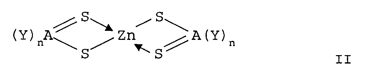
- said screen comprises at least one organozinc compound corresponding to the following general formula II : wherein R 7 and R 8 each independently represent a substituted or unsubstituted alkyl- or aryl group, or wherein R 7 and R 8 together form a ringstructure.
- screens comprising prompt emitting phosphor particles as well as screens comprising stimulable phosphor particles
- the wording phosphor screen is used to include both screens, comprising prompt emitting phosphor particles and screens comprising stimulable phosphor particles
- said zincdithiocarboylates correspond to general formula II : wherein R 7 and R 8 each independently represent a substituted or unsubstituted alkyl- or aryl group, or wherein R 7 and R 8 together form a ringstructure.
- the zinc-dithiocarboxylates are mixed before the manufacture of the screen with the dispersion of the phosphor particles in a solvent and optionally a binder.
- the stabilizing compounds according to the present invention are added in an amount of 10 -2 mole % to 5 mole % with respect to the phosphor.
- Preferably said compounds are mixed in an amount between 0.2 mole % and 2 mole % with respect to the phosphor.
- the zinc-dithiocarboxylates can be used to stabilize any phospor, both stimulable (storage phosphors) and prompt emitting phosphors.
- Typical examples of storage phosphors employable in a radiation image storage screen of the present invention include: SrS:Ce, Sm, SrS:Eu, Sm, ThO 2 :Er, and La 2 O 2 S:Eu, Sm, as described in U.S.
- M III OX:xCe in which M III is at least one trivalent metal selected from the group consisting of Pr, Nd, Pm, Sm, Eu, Tb, Dy, Ho, Er, Tm, Yb and Bi; X is at least one element selected from the group consisting of Cl and Br; and x is a number satisfying the condition of 0 ⁇ x ⁇ 0.1, as described in Japanese Patent Provisional Publication N°.
- LnOX:xA in which Ln is at least one element selected from the group consisting of La, Y, Gd and Lu, X is at least one element selected from the group consisting of Cl and Br, A is at least one element selected from the group consisting of Ce and Tb, and x is a number satisfying the condition of 0 ⁇ x ⁇ 0.1, as described in the above-mentioned U.S. Patent N°.
- Ba 1-x Sr x F 2-a-b Br a X b :zA wherein X is at least one member selected from the group consisting of Cl and I; x is in the range 0.10 ⁇ x ⁇ 0.55 ; a is in the range 0.70 ⁇ a ⁇ 0.96; b is in the range 0 ⁇ b ⁇ 0.15 ; z is in the range 10 -7 ⁇ z ⁇ 0.15, and A is Eu 2+ or Eu 2+ together with one or more of the co-dopants selected from the group consisting of Eu 3+ , Y, Tb, Ce, Tm, Dy, Pr, Ho, Nd, Yb, Er, La, Gd and Lu, and wherein fluorine is present stoichiometrically in said phosphor in a larger atom % than bromine taken alone or bromine combined with chlorine and/or iodine, as disclosed in EP 345 903.
- Alkali metal phosphors comprising earth alkali metals as disclosed in e.g. US-P 5,028,509 and EP 0 252 991. Alkalimetal phosphors as e.g. RbBr:Tl.
- Halosilicate phosphors as disclosed in, e.g.,EP 304 121, EP 382 295 and EP 522 619.
- Elpasolite phosphors as disclosed in European Application 94201578 filed on June 17, 1994
- the zinc-dithiocarboxylates, according to this invention can especially well be used to stabilize storage phosphor screens comprising a storage phosphor containing iodine, and are especially well suited for stabilizing bariumfluorohalide phosphors comprising iodine.
- the compounds, according to the present invention can be used to stabilize screens comprising any prompt emitting phosphor, e.g. CaWO 4 , BaFCl, BaFBr, Ba(F,Cl,I) 2 , Ba(F,Br,I) 2 , Y-tantalate phosphors as described in e.g. EP-A 202 875, Gd 2 O 2 S, LaOX phosphors, where X is one of Cl, Br or I, etc with or without dopants.
- any prompt emitting phosphor e.g. CaWO 4 , BaFCl, BaFBr, Ba(F,Cl,I) 2 , Ba(F,Br,I) 2 , Y-tantalate phosphors as described in e.g. EP-A 202 875, Gd 2 O 2 S, LaOX phosphors, where X is one of Cl, Br or I, etc with or without dopants.
- the zinc-dithiocarboxylates can especially well be used to stabilize prompt emitting X-ray screens comprising a prompt emitting phosphor being a member selected from the group consisting of a halide-containing rare earth metal phosphor in which the host metal is a rare earth metal and the activator is one or more other rare earth metals, a barium fluoride chloride or bromide phosphor activated by europium(II), a barium fluoride chloride or bromide phosphor activated by europium(II) comprising iodine and a sodium activated CsI phosphor.
- a prompt emitting phosphor being a member selected from the group consisting of a halide-containing rare earth metal phosphor in which the host metal is a rare earth metal and the activator is one or more other rare earth metals, a barium fluoride chloride or bromide phosphor activated by europium(II), a barium fluoride chloride or bro
- the screens comprising stabilizing compounds according to the present invention can be self supporting as well as supported.
- a supported and a self supporting screen comprise preferably a binder layer incorporating phosphor particles in dispersed form.
- the binder is preferably at least one film forming organic polymer, e.g. a cellulose acetate butyrate, polyalkyl (meth)acrylates, e.g. polymethyl methacrylate, a polyvinyl-n-butyral e.g.
- the weight ratio of phosphor to binder preferably from 80:20 to 99:1.
- the ratio by volume of phoshor to binding medium is preferably more than 85/15.
- the binding medium substantially consists of one or more hydrogenated styrene-diene block copolymers, having a saturated rubber block, as rubbery and/or elastomeric polymers as disclosed in WO 94/00531.
- Particularly suitable thermoplastic rubbers, used as block-copolymeric binders in phosphor screens in accordance with this invention are the KRATON-G rubbers, KRATON being a trade mark name from SHELL.
- the coverage of the phosphor is preferably in the range from about 5 and 250 mg/cm 2 , most preferably between 20 and 175 mg/cm 2 .
- the phosphor layer comprising a stabilizing compound according to the present invention
- said support is made of a film forming organic resin, e.g. polyethylene terephthalate, but paper supports and cardboard supports optionally coated with a resin layer such as an alpha-olefinic resin layer are also particularly useful. Further are mentioned glass supports and metal supports.
- the thickness of the phosphor layer is preferably in the range of 0.05 mm to 0.5 mm.
- Screens comprising stabilizing compound according to the present invention can be prepared by intimately mixing the phosphor in a solution of the binder and then coating on the support and drying.
- the coating of the present phosphor binder layer may proceed according to any usual technique, e.g. by spraying, dip-coating or doctor blade coating. After coating, the solvent(s) of the coating mixture is (are) removed by evaporation, e.g. by drying in a hot (60 °C) air current.
- An ultrasonic treatment can be applied to improve the packing density and to perform the de-aeration of the phosphor-binder combination.
- the phosphor-binder layer may be calandered to improve the packing density (i.e. the number of grams of phosphor per cm 3 of dry coating).
- a light-reflecting layer is provided between the phosphor-containing layer and its support to enhance the output of light emitted by photostimulation.
- a light-reflecting layer may contain white pigment particles dispersed in a binder, e.g. titanium dioxide particles, or it may be made of a vapour-deposited metal layer, e.g. an aluminium layer, or it may be a coloured pigment layer absorbing stimulating radiation but reflecting the emitted light as described e.g. in US-P 4,380,702.
- a layer absorbing the emitted light e.g. a layer containing carbon black or to use a coloured support e.g. a grey or black film support.
- the quartz tube was sealed with a flange with a water lock at the gas outlet side.
- the sealed quartz tube was placed in an oven at 850 o C, and the temperature was kept constant at this temperature during the three hour firing.
- the tube was flushed with Ar at a rate of 1.5 l/min.
- the tube was taken out of the furnace and allowed to cool.
- the flange was removed and the three crucibles were taken out of the tube.
- the powder was milled and homogenized.
- a second firing was performed at 750 o C, for 6 hours, under a 1.5 l/min 99.8% N 2 /0.2% H 2 gas flow rate. Finally, the powder was deagglomerated with a pestle and mortar.
- the phosphor corresponded to the formula : Ba 0.8175 Sr 0.18 Eu 0.001 Cs 0.0015 F 1.19 Br 0.70 I 0.11
- the phosphor was dispersed in a mixture of cellulose acetobutyrate/polyethylacetate binder.
- the solvents of the dispersion were methylethylketine, ethyleneglycolomonoethylether and ethylacetate.
- the phosphor was present in this dispersion a rato of 35 % by weight with respect to the total weight of the dispersion.
- the dispersion is coated with a bar coater on a support, such as to have 1000 g phosphor per m 2 .
- the phosphor was present in 89 % by weight with respect to the total weight of phosphor+binder.
- the screens, except the comparative screen comprised 1 % by weight with respect to the weight of the phosphor of the stabilizing compounds.
- the screens are subjected to an heat treatment of 45 minutes at 60 ° C. After this treatment the performance of the various screen was measured according to the procedure described herebelow.
- the phosphor screen is excited with an X-ray source operating at 85 kVp and 20 mA.
- the Nanophos X-ray source of Siemens AG-W Germany was used.
- the low energy X-rays are filtered out with a 21 mm thick aluminum plate to harden the X-ray spectrum.
- the phosphor screen is transferred in the dark to the measurement setup. In this setup laser light is used to photostimulate the X-ray irradiated phosphor screen.
- the laser used in this measurement is a CW Single Mode He-Ne laser with power 30 mW.
- the laser-optics comprise an electronic shutter, a beam-expander and a filter.
- a photomultiplier (Hamamatsu R 1398) collects the light emitted by the photostimulation and gives a corresponding electrical current.
- the measurement procedure is controlled by a Hewlett Packard Basic Controller 382 connected to a HP 6944 multiprogrammer. After amplification with a current to voltage convertor a TEKTRONIX TDS420 digital oscilloscope visualizes the photocurrent obtained.
- the electronic shutter is opened the laser beam begins to stimulate the phosphor screen and the digital oscilloscope is triggered.
- Using a diagfraghme placed in contact with the screen the light emitted by only 7 mm 2 is collected. Only half the laser power reaches the screen surface. In this way the intensity of the stimulating beam is more uniform.
- the signal amplitude from the photomultiplier is linear with the intensity of the photostimulating light and with the stored photostimulable energy.
- the signal decreases with a power law.
- the oscilloscope is triggered a second time to measure the offset which is defined as the component of error that is constant and independent of inputs. After subtracting this offset the point at wich the signal reaches 1/e of the maximum value is calculated. The integral below the curve is then calculated from the start to this 1/e point.
- the computer multiplies the integral with the sensitivity of the system.
- the sensitivity of the photomultiplier and amplifier have therefore to be measured as a function of anode-cathode voltage of the photomultiplier and the convolution of the emission spectrum of the phosphor and the transmission spectrum of the separating filter has to be calculated. Because the emission light is scattered in all directions only a fraction of the emitted light is detected by the photomultiplier.
- the position of the screen and photomultiplier are such that 10 % of the total emission is detected by the photomultiplier. After all these corrections have been made a conversion efficiency value (C.E.) is obtained in pJ/mm 3 /mR. This value varies with screen thickness and therefore for measurements to be comparable they have to be carried out at constant phosphor coverage.
- the stimulation energy (S.E.) is defined as the energy necessary to stimulate 63 % of the stored energy and is expressed ⁇ J/mm 2 .
- F.O.M. 1000 x C.E/S.E ..
- a screen was prepared as described above, without the additon of any stabilizing substance.
- the performance of the screen was measured in terms of CE, SE and FOM.
- screens were prepared as describe above with the addition of stabilizing substances.
- the performance of the screens was measured in terms of C.E.2, S.E. and FOM.
- Prompt emitting phosphor screen were made by dispersing a LaOBr:Tm phosphor in mixture of solvent and KRATON G (trade mark name from SHELL). The mixture was coated on a polyethyleneterephthalate film support so that 90 mg phosphor was present per cm 2 .
- the screen were cut into 4 seperate pieces. Four of these pieces were placed in an exsiccator filled with water that is maintained at 60 °C. The relative humidity is 100 %. After 6, 12, 18 and 24 one piece of the screen was taken out of the exsiccator and dried. After day 18, the three treated samples of the screen and one untreated sample of the screen were combined with a Blue sensitive X-ray film (AGFA CURIX RP1, trade name of Agfa-Gevaert NV, Mortsel, Belgium) and the sandwich exposed to X-rays of 70 kVp at a film focus distance of 1.5 m. The film/screen combination is exposed such as to give a density of 1.5 ( ⁇ 0.3) D on the film under the untreated screen sample.
- AGFA CURIX RP1 trade name of Agfa-Gevaert NV, Mortsel, Belgium
Abstract
said screen comprises at least one organozinc compound corresponding to the following general formula I :

A = either carbon or phosphorus
Y = -OR6 , -NR7R8, alkyl or aryl, wherein R6, R7 and R8 each independently represent a substituted or unsubstituted alkyl- or aryl group, or wherein R7 and R8 together form a ringstructure
n = 1 when A is carbon
n= 2 when A is phosphorus.
Description
- The invention relates to X-ray intensifying screens and stimulable phosphor screens. More particularly it relates to compositions that increase the stability of both X-ray intensifying screens and stimulable phosphor screens.
- In a conventional radiographic system an X-ray radiograph is obtained by X-rays transmitted imagewise through an object and converted into light of corresponding intensity in a so-called intensifying screen (X-ray conversion screen) wherein phosphor particles absorb the transmitted X-rays and convert them into visible light and/or ultraviolet radiation to which a photographic film is more sensitive than to the direct impact of X-rays.
- In practice the light emitted imagewise by said screen irradiates a contacting photographic silver halide emulsion layer film which after exposure is developed to form therein a silver image in conformity with the X-ray image.
- For use in common medical radiography the X-ray film comprises a transparent film support, coated on both sides with a silver halide emulsion layer. During the X-ray irradiation said film is arranged in a cassette between two X-ray conversion screens each of them making contact with its corresponding silver halide emulsion layer.
- According to another method of recording and reproducing an X-ray pattern disclosed e.g. in US-P 3,859,527 a special type of phosphor is used, known as a photostimulable phosphor, which being incorporated in a screen is exposed to incident pattern-wise modulated X-rays and as a result thereof temporarily stores therein energy contained in the X-ray radiation pattern. At some interval after the exposure, a beam of visible or infrared light scans the screen to stimulate the release of stored energy as light that is detected and converted to sequential electrical signals which are processable to produce a visible image. For this purpose, the phosphor should store as much as possible of the incident X-ray energy and emit as little as possible of the stored energy until stimulated by the scanning beam.
- In both systems phosphor particles are dispersed in a binder and by coating the dispersion of phosphor particles on a support a supported screen is formed, or by casting the dispersion a self-supporting screen is formed. The screens have to withstand not only physical strains but also strain due to environmental causes especially humidity and heat. Due to humidity and heat, some phosphors, contained in the screen tend to decompose. This decomposition can be homogeneous, e.g. a coloration over all the surface of the screen, thus diminishing the speed of the X-ray system by absorbing emitted light (promptly emitted light as well as stimulated emission light). The deterioration of the screen due to phosphor decomposition can be local, thus diminishing the image quality of the system because in some place no image or a blurred image is formed.
- It has been described in GB 1,575,511 that the derioration of X-ray intensifying screens comprising a halide-containing rare earth metal phosphor in which the host metal is a rare earth metal and the activator is one or more other rare earth metals or a barium fluoride chloride phosphor activated by europium(II) or a sodium activated CsI phosphor could be diminished by the addition to the screen of metal-organic substances. Although this disclosure claims the use of metal-organic substances, the examples of this disclosure are mainly focussed on organotin substances.
- In EP-A 234 385 it is disclosed that a storage screen (i.e. a stimulable phosphor screen) comprising a iodine containing bariumflorohalide fosfor could be stabilized by the addition of organotin compounds and or compounds having an epoxygroup.
- Up until now the stabilizing compounds had in practice to be organotin compounds. This restriction limits the degrees of freedom when preparing intensifying screens or stimulable phosphor screens. The binder, solvent and further ingredients of the coating solution of such a screen had always to be chosen so that there always was a compatibility with organotin compounds. Therefore it is still desirable to find further stabilizing compounds for use in both X-ray intensifying screen and (photo)stimulable screens.
- It is an object of the invention to provide screens comprising prompt emitting phosphor particles, as well as screens comprising stimulable phosphor particles, that are basically insensitive to environmental influences.
- It is another object of the invention to provide screens, as described above, that are stabilized against the influence of moisture.
- It is an object of the invention to provide further means for stabilizing screens comprising prompt emitting phosphor particles or stimulable phosphor particles so that the degree of freedom during manufacture of said screens is enhanced.
- Further objects and advantages will become clear from the detailed description hereinafter.
- The objects of the invention are realized by providing a phosphor screen, characterised in that said screen comprises at least one organozinc compound corresponding to the following general formula I :

A = either carbon or phosphorus
Y = -OR6 , -NR7R8, alkyl or aryl, wherein R6, R7 and R8 each independently represent a substituted or unsubstituted alkyl- or aryl group, or wherein R7 and R8 together form a ringstructure
n = 1 when A is carbon
n= 2 when A is phosphorus. - In a preferred embodiment said screen comprises at least one organozinc compound corresponding to the following general formula II :

- It was surprisingly found that screens, comprising prompt emitting phosphor particles as well as screens comprising stimulable phosphor particles, (hereinafter the wording phosphor screen is used to include both screens, comprising prompt emitting phosphor particles and screens comprising stimulable phosphor particles) could be stabilized against degradation due to environmental influences (temperature, humidity, acidic atmosphere, etc) by the addition to the phosphor comprising layer of said screens of Zn-dithiocarboxylates corresponding to general formula I :
A = either carbon or phosphorus
Y = -OR6 , -NR7R8, alkyl or aryl, wherein R6, R7 and R8 each independently represent a substituted or unsubstituted alkyl- or aryl group, or wherein R7 and R8 together form a ringstructure
n = 1 when A is carbon
n= 2 when A is phosphorus. - In a preferred embodiment, said zincdithiocarboylates correspond to general formula II :

- Specific examples of very useful zincdithiocarboxylates according to the present invention, are compounds A1 to A4 :


- The zinc-dithiocarboxylates are mixed before the manufacture of the screen with the dispersion of the phosphor particles in a solvent and optionally a binder. The stabilizing compounds according to the present invention are added in an amount of 10-2 mole % to 5 mole % with respect to the phosphor. Preferably said compounds are mixed in an amount between 0.2 mole % and 2 mole % with respect to the phosphor.
- The zinc-dithiocarboxylates, according to this invention, can be used to stabilize any phospor, both stimulable (storage phosphors) and prompt emitting phosphors. Typical examples of storage phosphors employable in a radiation image storage screen of the present invention include:
SrS:Ce, Sm, SrS:Eu, Sm, ThO2:Er, and La2O2S:Eu, Sm, as described in U.S. Patent N°.3,859,527;
ZnS:Cu,Pb, BaO.xAl2O3:Eu, in which x is a number satisfying the condition of 0.8 ≦ x ≦ 10, and M2+O.xSiO2:A, in which M2+ is at least one divalent metal selected from the group consisting of Mg, Ca, Sr, Zn, Cd and Ba, A is at least one element selected from the group consisting of Ce, Tb, Eu, Tm, Pb, Tl, Bi and Mn, and x is a number satisfying the condition of 0.5 ≦ x ≦ 2.5, as described in U.S. Patent N°. 4,326,078;
MIIIOX:xCe, in which MIII is at least one trivalent metal selected from the group consisting of Pr, Nd, Pm, Sm, Eu, Tb, Dy, Ho, Er, Tm, Yb and Bi; X is at least one element selected from the group consisting of Cl and Br; and x is a number satisfying the condition of 0 < x < 0.1, as described in Japanese Patent Provisional Publication N°. 58(1983)-69281;
LnOX:xA, in which Ln is at least one element selected from the group consisting of La, Y, Gd and Lu, X is at least one element selected from the group consisting of Cl and Br, A is at least one element selected from the group consisting of Ce and Tb, and x is a number satisfying the condition of 0 < x < 0.1, as described in the above-mentioned U.S. Patent N°. 4,236,078;
(Ba1-x,MII x)FX:yA, in which MII is at least one divalent metal selected from the group consisting of Mg, Ca, Sr, Zn and Cd, X is at least one element selected from the group consisting of Cl, Br and I, A is at least one element selected from the group consisting of Eu, Tb, Ce, Tm, Dy, Pr, Ho, Nd, Yb and Er, and x and y are numbers satisfying the conditions of 0 ≦ x ≦ 0.6 and 0 ≦ y ≦ 0.2 respectively, as described in US-P 4,239,968. - Bariumfluorohalide phosphors as disclosed in, e.g., US P 4.239.968, DE OS 2 928 245, US-P 4 261 854, US-P 4 539 138, US P 4.512.911, EP 0 029 963, US-P 4 336 154, US-P 5 077 144, US-P 4 948 696,Japanese Patent Provisional Publication N°. 55(1980)-12143, Japanese Patent Provisional Publication N°. 56(1981)-116777, Japanese Patent Provisional Publication N°. 57(1982)-23675, US-P 5 089 170, US-P 4 532 071, DE OS 3 304 216, EP 0 142 734, EP 0 144 772, US-P 4 587 036, US-P 4 608 190, and EP 0 295 522.
- Ba1-xSrxF2-a-bBraXb:zA, wherein X is at least one member selected from the group consisting of Cl and I; x is in the range 0.10 ≦ x ≦ 0.55 ; a is in the range 0.70 ≦ a ≦ 0.96; b is in the range 0 ≦ b < 0.15 ; z is in the range 10-7 < z ≦ 0.15, and A is Eu2+ or Eu2+ together with one or more of the co-dopants selected from the group consisting of Eu3+, Y, Tb, Ce, Tm, Dy, Pr, Ho, Nd, Yb, Er, La, Gd and Lu, and wherein fluorine is present stoichiometrically in said phosphor in a larger atom % than bromine taken alone or bromine combined with chlorine and/or iodine, as disclosed in EP 345 903.
- Alkali metal phosphors comprising earth alkali metals as disclosed in e.g. US-P 5,028,509 and EP 0 252 991. Alkalimetal phosphors as e.g. RbBr:Tl.
- Halosilicate phosphors as disclosed in, e.g.,EP 304 121, EP 382 295 and EP 522 619.
- Elpasolite phosphors as disclosed in European Application 94201578 filed on June 17, 1994
The zinc-dithiocarboxylates, according to this invention, can especially well be used to stabilize storage phosphor screens comprising a storage phosphor containing iodine, and are especially well suited for stabilizing bariumfluorohalide phosphors comprising iodine. - The compounds, according to the present invention, can be used to stabilize screens comprising any prompt emitting phosphor, e.g. CaWO4, BaFCl, BaFBr, Ba(F,Cl,I)2, Ba(F,Br,I)2, Y-tantalate phosphors as described in e.g. EP-A 202 875, Gd2O2S, LaOX phosphors, where X is one of Cl, Br or I, etc with or without dopants. The zinc-dithiocarboxylates can especially well be used to stabilize prompt emitting X-ray screens comprising a prompt emitting phosphor being a member selected from the group consisting of a halide-containing rare earth metal phosphor in which the host metal is a rare earth metal and the activator is one or more other rare earth metals, a barium fluoride chloride or bromide phosphor activated by europium(II), a barium fluoride chloride or bromide phosphor activated by europium(II) comprising iodine and a sodium activated CsI phosphor.
- The screens comprising stabilizing compounds according to the present invention can be self supporting as well as supported. A supported and a self supporting screen comprise preferably a binder layer incorporating phosphor particles in dispersed form. The binder is preferably at least one film forming organic polymer, e.g. a cellulose acetate butyrate, polyalkyl (meth)acrylates, e.g. polymethyl methacrylate, a polyvinyl-n-butyral e.g. as described in the US-P 3,043,710, a copoly(vinyl acetate/vinyl chloride) and a copoly(acrylonitrile/butadiene/styrene) or a copoly(vinyl chloride/vinyl acetate/vinyl alcohol) or mixture thereof.
- When a binder is used, it is most preferred to use a minimum amount of binder. The weight ratio of phosphor to binder preferably from 80:20 to 99:1. The ratio by volume of phoshor to binding medium is preferably more than 85/15.
- Preferably the binding medium substantially consists of one or more hydrogenated styrene-diene block copolymers, having a saturated rubber block, as rubbery and/or elastomeric polymers as disclosed in WO 94/00531. Particularly suitable thermoplastic rubbers, used as block-copolymeric binders in phosphor screens in accordance with this invention are the KRATON-G rubbers, KRATON being a trade mark name from SHELL.
- The coverage of the phosphor is preferably in the range from about 5 and 250 mg/cm2, most preferably between 20 and 175 mg/cm2.
- When the phosphor layer, comprising a stabilizing compound according to the present invention, is used as a supported layer on a support sheet, said support is made of a film forming organic resin, e.g. polyethylene terephthalate, but paper supports and cardboard supports optionally coated with a resin layer such as an alpha-olefinic resin layer are also particularly useful. Further are mentioned glass supports and metal supports. The thickness of the phosphor layer is preferably in the range of 0.05 mm to 0.5 mm.
- Screens comprising stabilizing compound according to the present invention, can be prepared by intimately mixing the phosphor in a solution of the binder and then coating on the support and drying. The coating of the present phosphor binder layer may proceed according to any usual technique, e.g. by spraying, dip-coating or doctor blade coating. After coating, the solvent(s) of the coating mixture is (are) removed by evaporation, e.g. by drying in a hot (60 °C) air current.
- An ultrasonic treatment can be applied to improve the packing density and to perform the de-aeration of the phosphor-binder combination. Before the optional application of a protective coating the phosphor-binder layer may be calandered to improve the packing density (i.e. the number of grams of phosphor per cm3 of dry coating).
- Optionally, a light-reflecting layer is provided between the phosphor-containing layer and its support to enhance the output of light emitted by photostimulation. Such a light-reflecting layer may contain white pigment particles dispersed in a binder, e.g. titanium dioxide particles, or it may be made of a vapour-deposited metal layer, e.g. an aluminium layer, or it may be a coloured pigment layer absorbing stimulating radiation but reflecting the emitted light as described e.g. in US-P 4,380,702.
- In order to improve resolution it is possible to provide underneath the phosphor layer a layer absorbing the emitted light e.g. a layer containing carbon black or to use a coloured support e.g. a grey or black film support.
- All stimulable phosphor samples have been prepared in the following way:
The phosphor precursors :BaF2: 0.819 mol SrF2: 0.18 mol NH4Br: 0.82 mol NH4I: 0.15 mol EuF3: 0.001 mol CsI: 0.003 mol.
Three crucibles containing 130 g of the mix each, were placed in a quartz tube. The quartz tube was sealed with a flange with a water lock at the gas outlet side.
The sealed quartz tube was placed in an oven at 850oC, and the temperature was kept constant at this temperature during the three hour firing. During the firing the tube was flushed with Ar at a rate of 1.5 l/min.
After the firing, the tube was taken out of the furnace and allowed to cool.
After the cooling, the flange was removed and the three crucibles were taken out of the tube.
The powder was milled and homogenized.
A second firing was performed at 750oC, for 6 hours, under a 1.5 l/min 99.8% N2/0.2% H2 gas flow rate.
Finally, the powder was deagglomerated with a pestle and mortar. The phosphor corresponded to the formula :
Ba0.8175Sr0.18Eu0.001Cs0.0015F1.19Br0.70I0.11
- The phosphor was dispersed in a mixture of cellulose acetobutyrate/polyethylacetate binder. The solvents of the dispersion were methylethylketine, ethyleneglycolomonoethylether and ethylacetate. The phosphor was present in this dispersion a rato of 35 % by weight with respect to the total weight of the dispersion. The dispersion is coated with a bar coater on a support, such as to have 1000 g phosphor per m2. In the finished screen, the phosphor was present in 89 % by weight with respect to the total weight of phosphor+binder.
The screens, except the comparative screen comprised 1 % by weight with respect to the weight of the phosphor of the stabilizing compounds. - The screens are subjected to an heat treatment of 45 minutes at 60 ° C. After this treatment the performance of the various screen was measured according to the procedure described herebelow. The phosphor screen is excited with an X-ray source operating at 85 kVp and 20 mA. For that purpose the Nanophos X-ray source of Siemens AG-W Germany was used. The low energy X-rays are filtered out with a 21 mm thick aluminum plate to harden the X-ray spectrum. After X-ray excitation the phosphor screen is transferred in the dark to the measurement setup. In this setup laser light is used to photostimulate the X-ray irradiated phosphor screen. The laser used in this measurement is a CW Single Mode He-Ne laser with power 30 mW.
- The laser-optics comprise an electronic shutter, a beam-expander and a filter. A photomultiplier (Hamamatsu R 1398) collects the light emitted by the photostimulation and gives a corresponding electrical current. The measurement procedure is controlled by a Hewlett Packard Basic Controller 382 connected to a HP 6944 multiprogrammer. After amplification with a current to voltage convertor a TEKTRONIX TDS420 digital oscilloscope visualizes the photocurrent obtained. When the electronic shutter is opened the laser beam begins to stimulate the phosphor screen and the digital oscilloscope is triggered. Using a diagfraghme placed in contact with the screen the light emitted by only 7 mm2 is collected. Only half the laser power reaches the screen surface. In this way the intensity of the stimulating beam is more uniform.
- The signal amplitude from the photomultiplier is linear with the intensity of the photostimulating light and with the stored photostimulable energy. The signal decreases with a power law. When the signal curve is enterred the oscilloscope is triggered a second time to measure the offset which is defined as the component of error that is constant and independent of inputs. After subtracting this offset the point at wich the signal reaches 1/e of the maximum value is calculated. The integral below the curve is then calculated from the start to this 1/e point. The function is described mathematyically by

- The 1/e point is reached when

- The stimulation energy (S.E.) is defined as the energy necessary to stimulate 63 % of the stored energy and is expressed µJ/mm2.
- From the values C.E. and S.E. a figure of merit (F.O.M.) that is a value describing the sensitivity of the phosphor for practical use.

- A screen was prepared as described above, without the additon of any stabilizing substance. The performance of the screen was measured in terms of CE, SE and FOM.
- For these examples, screens were prepared as describe above with the addition of stabilizing substances. The performance of the screens was measured in terms of C.E.2, S.E. and FOM.
- The stabilizing substance used and the performance of the various screens are listed in table 1.
TABLE 1 Nr. Stabilizer C.E.2 (pJ/mm3/mR) S.E (µJ/mm2) FOM C1 none 1.5 30 50 E1 A1 57 15 3900 E2 A2 43 17 2529 E3 A3 42 16 2625 E4 A4 48 16 3000 - Prompt emitting phosphor screen were made by dispersing a LaOBr:Tm phosphor in mixture of solvent and KRATON G (trade mark name from SHELL). The mixture was coated on a polyethyleneterephthalate film support so that 90 mg phosphor was present per cm2.
- Two screens were prepared : C2 without any stabilizer, E5 with stabilizer A1.
- The screen were cut into 4 seperate pieces. Four of these pieces were placed in an exsiccator filled with water that is maintained at 60 °C. The relative humidity is 100 %. After 6, 12, 18 and 24 one piece of the screen was taken out of the exsiccator and dried. After day 18, the three treated samples of the screen and one untreated sample of the screen were combined with a Blue sensitive X-ray film (AGFA CURIX RP1, trade name of Agfa-Gevaert NV, Mortsel, Belgium) and the sandwich exposed to X-rays of 70 kVp at a film focus distance of 1.5 m. The film/screen combination is exposed such as to give a density of 1.5 (± 0.3) D on the film under the untreated screen sample. The difference in density of the film under the untreated sample and the density under the treated samples is taken as a measure of stability. The smaller the density difference, the more stable the screen.
The results are given in Table 2.TABLE 2 Nr Stabilizer ΔD* ΔD** C2 none - 0.285 - 0.375 E5 A1 - 0.020 - 0.306 * difference in density under the untreated screen and under the screen treated for 12 days. ** difference in density under the untreated screen and under the screen treated for 18 days.
Claims (7)
- A phosphor screen, characterised in that
said screen comprises at least one organozinc compound corresponding to the following general formula I :
A = either carbon or phosphorus
Y = -OR6 , -NR7R8, alkyl or aryl, wherein R6, R7 and R8 each independently represent a substituted or unsubstituted alkyl- or aryl group, or wherein R7 and R8 together form a ringstructure
n = 1 when A is carbon
n= 2 when A is phosphorus. - A phosphor screen according to claim 1, wherein said organozinc compound corresponds to general formula II :

- A phosphor screen according to claim 1 or 2, wherein said organozinc compound is present in an amount of 10-2 mole % to 5 mole % with respect to the phosphor.
- A phosphor screen according to any of the preceding claims, wherein said screen comprises a stimulable phosphor.
- A phosphor screen according to claim 4, wherein said stimulable phosphor is a bariumfluorohalide phosphor comprising iodine.
- A phosphor screen according to any of claims 1 to 3, wherein said screen comprises a prompt emitting phosphor.
- A phosphor screen according to claim 6, wherein said prompt emitting phosphor is a member selected from the group consisting of a halide-containing rare earth metal phosphor in which the host metal is a rare earth metal and the activator is one or more other rare earth metals, a barium fluoride chloride or bromide phosphor activated by europium(II), a barium fluoride chloride or bromide phosphor activated by europium(II) comprising iodine and a sodium activated CsI phosphor.
Priority Applications (3)
| Application Number | Priority Date | Filing Date | Title |
|---|---|---|---|
| EP95201434A EP0745657B1 (en) | 1995-06-01 | 1995-06-01 | A novel class of stabilizing compounds for phosphor screens |
| DE69505105T DE69505105T2 (en) | 1995-06-01 | 1995-06-01 | New class of stabilizing compounds for phosphor screens |
| US08/654,612 US5632930A (en) | 1995-06-01 | 1996-05-29 | Class of stabilizing compounds for phosphor screens |
Applications Claiming Priority (1)
| Application Number | Priority Date | Filing Date | Title |
|---|---|---|---|
| EP95201434A EP0745657B1 (en) | 1995-06-01 | 1995-06-01 | A novel class of stabilizing compounds for phosphor screens |
Publications (2)
| Publication Number | Publication Date |
|---|---|
| EP0745657A1 true EP0745657A1 (en) | 1996-12-04 |
| EP0745657B1 EP0745657B1 (en) | 1998-09-30 |
Family
ID=8220343
Family Applications (1)
| Application Number | Title | Priority Date | Filing Date |
|---|---|---|---|
| EP95201434A Expired - Lifetime EP0745657B1 (en) | 1995-06-01 | 1995-06-01 | A novel class of stabilizing compounds for phosphor screens |
Country Status (3)
| Country | Link |
|---|---|
| US (1) | US5632930A (en) |
| EP (1) | EP0745657B1 (en) |
| DE (1) | DE69505105T2 (en) |
Families Citing this family (3)
| Publication number | Priority date | Publication date | Assignee | Title |
|---|---|---|---|---|
| DE19930645A1 (en) * | 1999-07-02 | 2001-01-11 | Rainer Kassing | Reusable image plate with a storage phosphor for storing X-ray images and manufacturing method for a reusable image plate |
| JP3651801B2 (en) * | 2003-06-30 | 2005-05-25 | 九州電力株式会社 | Electroluminescent device |
| EP1494067B1 (en) * | 2003-07-02 | 2008-01-23 | Agfa-Gevaert HealthCare GmbH | System comprising a scanner and a storage layer, as well as a storage layer for storing x-ray information |
Citations (35)
| Publication number | Priority date | Publication date | Assignee | Title |
|---|---|---|---|---|
| US3043710A (en) | 1959-02-20 | 1962-07-10 | Du Pont | Fluorescent screens |
| US3859527A (en) | 1973-01-02 | 1975-01-07 | Eastman Kodak Co | Apparatus and method for producing images corresponding to patterns of high energy radiation |
| DE2928245A1 (en) | 1978-07-12 | 1980-01-24 | Fuji Photo Film Co Ltd | EARTH ALKALINE-METAL FLUORO-HALOGENIDE LUMINAIRE ACTIVATED WITH TWO-VALUE EUROPE |
| GB1575511A (en) | 1976-03-18 | 1980-09-24 | Agfa Gevaert | Luminescent composition for radiation-conversion screens |
| US4239968A (en) | 1978-07-12 | 1980-12-16 | Fuji Photo Film Co., Ltd. | Method and apparatus for recording and reproducing a radiation image |
| US4261854A (en) | 1978-12-21 | 1981-04-14 | Kasei Optonix, Ltd. | Phosphor |
| EP0029963A1 (en) | 1979-11-21 | 1981-06-10 | Fuji Photo Film Co., Ltd. | Phosphor and radiation image storage panel utilizing the same |
| JPS56116777A (en) | 1980-02-20 | 1981-09-12 | Kasei Optonix Co Ltd | Phosphor and radiation image transformation panel using the same |
| JPS56118442A (en) * | 1980-02-22 | 1981-09-17 | Sankyo Yuki Gosei Kk | Halogen-containing resin composition |
| JPS5723675A (en) | 1980-07-16 | 1982-02-06 | Kasei Optonix Co Ltd | Fluorescent substance and radiation image conversion panel using the same |
| US4326078A (en) | 1978-07-31 | 1982-04-20 | Dynamit Noble Aktiengesellschaft | Process for preparation of hydrazobenzenes by catalytic hydrogenation of nitrobenzenes |
| US4336154A (en) | 1981-07-14 | 1982-06-22 | Kasei Optonix, Ltd. | Phosphor and radiation image storage panel utilizing the same |
| US4380702A (en) | 1979-07-11 | 1983-04-19 | Fuji Photo Film Co., Ltd. | Radiation image storage panel |
| JPS5869281A (en) | 1981-10-20 | 1983-04-25 | Fuji Photo Film Co Ltd | Oxyhalide phosphor |
| DE3304216A1 (en) | 1983-02-08 | 1984-08-09 | Siemens AG, 1000 Berlin und 8000 München | X-ray image storage screen |
| US4512911A (en) | 1979-06-19 | 1985-04-23 | Kasei Optonix, Ltd. | Phosphor |
| EP0142734A1 (en) | 1983-10-24 | 1985-05-29 | Fuji Photo Film Co., Ltd. | Radiation image recording and reproducing method |
| EP0144772A1 (en) | 1983-11-07 | 1985-06-19 | Fuji Photo Film Co., Ltd. | Phosphor, radiation image recordng and reproducing method and radiation image storage panel employing the same |
| US4532071A (en) | 1982-08-24 | 1985-07-30 | Fuji Photo Film Co., Ltd. | Process for the preparation of phosphor |
| US4539138A (en) | 1979-05-25 | 1985-09-03 | Fuji Photo Film Co. Ltd. | Phosphor |
| US4587036A (en) | 1983-12-27 | 1986-05-06 | Siemens Aktiengesellschaft | X-ray image storage screen |
| US4608190A (en) | 1984-04-23 | 1986-08-26 | E. I. Du Pont De Nemours And Company | X-ray image storage panel comprising anion-deficient BaFCl:Eu/BaFBr:Eu phosphors |
| EP0202875A2 (en) | 1985-05-18 | 1986-11-26 | Nichia Kagaku Kogyo K.K. | X-ray phosphors and the process for producing the same |
| EP0234385A1 (en) | 1986-02-07 | 1987-09-02 | Fuji Photo Film Co., Ltd. | Radiation image storage panel |
| EP0252991A1 (en) | 1985-12-28 | 1988-01-20 | Konishiroku Photo Ind | Alkali halide phosphor. |
| EP0295522A1 (en) | 1987-06-15 | 1988-12-21 | Siemens Aktiengesellschaft | Stimulable storage phosphor |
| EP0304121A1 (en) | 1987-08-17 | 1989-02-22 | Agfa-Gevaert N.V. | Reproduction of X-ray images with a photostimulable phosphor |
| EP0345903A2 (en) | 1988-06-10 | 1989-12-13 | Agfa-Gevaert N.V. | Photostimulable phosphor |
| US4900641A (en) * | 1986-02-07 | 1990-02-13 | Fuji Photo Film Co., Ltd. | Radiographic intensifying screen |
| US4948696A (en) | 1981-12-24 | 1990-08-14 | Fuji Photo Film Co., Ltd. | Radiation image recording and reproducing method |
| EP0382295A2 (en) | 1989-02-07 | 1990-08-16 | Agfa-Gevaert N.V. | Reproduction of X-ray images with photostimulable phosphor |
| US5028509A (en) | 1984-09-14 | 1991-07-02 | Konica Corporation | Method for converting radiographic image, radiation energy storage panel having stimulable phosphor-containing layer and alkali halide phosphor |
| US5077144A (en) | 1981-12-24 | 1991-12-31 | Fuji Photo Film Co., Ltd. | Phosphor and radiographic intensifying screen |
| US5089170A (en) | 1982-05-28 | 1992-02-18 | Fuji Photo Film Co., Ltd. | Phosphor |
| WO1994000531A1 (en) | 1992-06-23 | 1994-01-06 | Agfa-Gevaert Naamloze Vennootschap | Luminescent article with high pigment to binder ratio and manufacture thereof |
-
1995
- 1995-06-01 DE DE69505105T patent/DE69505105T2/en not_active Expired - Fee Related
- 1995-06-01 EP EP95201434A patent/EP0745657B1/en not_active Expired - Lifetime
-
1996
- 1996-05-29 US US08/654,612 patent/US5632930A/en not_active Expired - Fee Related
Patent Citations (36)
| Publication number | Priority date | Publication date | Assignee | Title |
|---|---|---|---|---|
| US3043710A (en) | 1959-02-20 | 1962-07-10 | Du Pont | Fluorescent screens |
| US3859527A (en) | 1973-01-02 | 1975-01-07 | Eastman Kodak Co | Apparatus and method for producing images corresponding to patterns of high energy radiation |
| GB1575511A (en) | 1976-03-18 | 1980-09-24 | Agfa Gevaert | Luminescent composition for radiation-conversion screens |
| DE2928245A1 (en) | 1978-07-12 | 1980-01-24 | Fuji Photo Film Co Ltd | EARTH ALKALINE-METAL FLUORO-HALOGENIDE LUMINAIRE ACTIVATED WITH TWO-VALUE EUROPE |
| JPS5512143A (en) | 1978-07-12 | 1980-01-28 | Dainippon Toryo Co Ltd | Fluorescent material |
| US4239968A (en) | 1978-07-12 | 1980-12-16 | Fuji Photo Film Co., Ltd. | Method and apparatus for recording and reproducing a radiation image |
| US4326078A (en) | 1978-07-31 | 1982-04-20 | Dynamit Noble Aktiengesellschaft | Process for preparation of hydrazobenzenes by catalytic hydrogenation of nitrobenzenes |
| US4261854A (en) | 1978-12-21 | 1981-04-14 | Kasei Optonix, Ltd. | Phosphor |
| US4539138A (en) | 1979-05-25 | 1985-09-03 | Fuji Photo Film Co. Ltd. | Phosphor |
| US4512911A (en) | 1979-06-19 | 1985-04-23 | Kasei Optonix, Ltd. | Phosphor |
| US4380702A (en) | 1979-07-11 | 1983-04-19 | Fuji Photo Film Co., Ltd. | Radiation image storage panel |
| EP0029963A1 (en) | 1979-11-21 | 1981-06-10 | Fuji Photo Film Co., Ltd. | Phosphor and radiation image storage panel utilizing the same |
| JPS56116777A (en) | 1980-02-20 | 1981-09-12 | Kasei Optonix Co Ltd | Phosphor and radiation image transformation panel using the same |
| JPS56118442A (en) * | 1980-02-22 | 1981-09-17 | Sankyo Yuki Gosei Kk | Halogen-containing resin composition |
| JPS5723675A (en) | 1980-07-16 | 1982-02-06 | Kasei Optonix Co Ltd | Fluorescent substance and radiation image conversion panel using the same |
| US4336154A (en) | 1981-07-14 | 1982-06-22 | Kasei Optonix, Ltd. | Phosphor and radiation image storage panel utilizing the same |
| JPS5869281A (en) | 1981-10-20 | 1983-04-25 | Fuji Photo Film Co Ltd | Oxyhalide phosphor |
| US4948696A (en) | 1981-12-24 | 1990-08-14 | Fuji Photo Film Co., Ltd. | Radiation image recording and reproducing method |
| US5077144A (en) | 1981-12-24 | 1991-12-31 | Fuji Photo Film Co., Ltd. | Phosphor and radiographic intensifying screen |
| US5089170A (en) | 1982-05-28 | 1992-02-18 | Fuji Photo Film Co., Ltd. | Phosphor |
| US4532071A (en) | 1982-08-24 | 1985-07-30 | Fuji Photo Film Co., Ltd. | Process for the preparation of phosphor |
| DE3304216A1 (en) | 1983-02-08 | 1984-08-09 | Siemens AG, 1000 Berlin und 8000 München | X-ray image storage screen |
| EP0142734A1 (en) | 1983-10-24 | 1985-05-29 | Fuji Photo Film Co., Ltd. | Radiation image recording and reproducing method |
| EP0144772A1 (en) | 1983-11-07 | 1985-06-19 | Fuji Photo Film Co., Ltd. | Phosphor, radiation image recordng and reproducing method and radiation image storage panel employing the same |
| US4587036A (en) | 1983-12-27 | 1986-05-06 | Siemens Aktiengesellschaft | X-ray image storage screen |
| US4608190A (en) | 1984-04-23 | 1986-08-26 | E. I. Du Pont De Nemours And Company | X-ray image storage panel comprising anion-deficient BaFCl:Eu/BaFBr:Eu phosphors |
| US5028509A (en) | 1984-09-14 | 1991-07-02 | Konica Corporation | Method for converting radiographic image, radiation energy storage panel having stimulable phosphor-containing layer and alkali halide phosphor |
| EP0202875A2 (en) | 1985-05-18 | 1986-11-26 | Nichia Kagaku Kogyo K.K. | X-ray phosphors and the process for producing the same |
| EP0252991A1 (en) | 1985-12-28 | 1988-01-20 | Konishiroku Photo Ind | Alkali halide phosphor. |
| EP0234385A1 (en) | 1986-02-07 | 1987-09-02 | Fuji Photo Film Co., Ltd. | Radiation image storage panel |
| US4900641A (en) * | 1986-02-07 | 1990-02-13 | Fuji Photo Film Co., Ltd. | Radiographic intensifying screen |
| EP0295522A1 (en) | 1987-06-15 | 1988-12-21 | Siemens Aktiengesellschaft | Stimulable storage phosphor |
| EP0304121A1 (en) | 1987-08-17 | 1989-02-22 | Agfa-Gevaert N.V. | Reproduction of X-ray images with a photostimulable phosphor |
| EP0345903A2 (en) | 1988-06-10 | 1989-12-13 | Agfa-Gevaert N.V. | Photostimulable phosphor |
| EP0382295A2 (en) | 1989-02-07 | 1990-08-16 | Agfa-Gevaert N.V. | Reproduction of X-ray images with photostimulable phosphor |
| WO1994000531A1 (en) | 1992-06-23 | 1994-01-06 | Agfa-Gevaert Naamloze Vennootschap | Luminescent article with high pigment to binder ratio and manufacture thereof |
Non-Patent Citations (1)
| Title |
|---|
| DATABASE WPI Section Ch Week 8144, Derwent World Patents Index; Class A14, AN 81-80573D * |
Also Published As
| Publication number | Publication date |
|---|---|
| DE69505105T2 (en) | 1999-04-08 |
| DE69505105D1 (en) | 1998-11-05 |
| US5632930A (en) | 1997-05-27 |
| EP0745657B1 (en) | 1998-09-30 |
Similar Documents
| Publication | Publication Date | Title |
|---|---|---|
| EP0104652B1 (en) | Phosphor and radiation image storage panel employing the same | |
| EP0144772B1 (en) | Phosphor, radiation image recordng and reproducing method and radiation image storage panel employing the same | |
| EP0345903B1 (en) | Photostimulable phosphor | |
| JPS6230237B2 (en) | ||
| EP0168036B1 (en) | Phosphor and radiation image storage panel employing the same | |
| EP0745657B1 (en) | A novel class of stabilizing compounds for phosphor screens | |
| EP0747908B1 (en) | A novel class of stabilizing compounds for phosphor screens | |
| EP0146974B1 (en) | Phosphor and radiation image storage panel employing the same | |
| US5569926A (en) | Radiation image recording and reproducing method | |
| US4999515A (en) | Radiation image recording and reproducing method | |
| EP0148507B1 (en) | Phosphor and radiation image storage panel employing the same | |
| EP0168057B1 (en) | Phosphor, radiation image recording and reproducing method and radiation image storage panel | |
| US4876161A (en) | Phosphor and radiation image storage panel | |
| EP0264922B1 (en) | Phosphor and radiation image storage panel employing the same | |
| US5624603A (en) | Bariumfluorohalide phosphor comprising calcium ions at the surface | |
| EP0151494B1 (en) | Phosphor, radiation image recording and reproducing method and radiation image storage panel | |
| EP0704511B1 (en) | A radiation image recording and reproducing method | |
| US4895772A (en) | Phosphor, and radiation image storage panel | |
| JPS6332112B2 (en) | ||
| JPH0885786A (en) | Cerium-activated barium halide phosphor and radiological image conversion panel | |
| JPH07126617A (en) | Cerium-activated barium fluorohalide-based fluorescent material and radiological image conversion panel |
Legal Events
| Date | Code | Title | Description |
|---|---|---|---|
| PUAI | Public reference made under article 153(3) epc to a published international application that has entered the european phase |
Free format text: ORIGINAL CODE: 0009012 |
|
| AK | Designated contracting states |
Kind code of ref document: A1 Designated state(s): BE DE FR GB NL |
|
| 17P | Request for examination filed |
Effective date: 19970604 |
|
| GRAG | Despatch of communication of intention to grant |
Free format text: ORIGINAL CODE: EPIDOS AGRA |
|
| GRAG | Despatch of communication of intention to grant |
Free format text: ORIGINAL CODE: EPIDOS AGRA |
|
| GRAH | Despatch of communication of intention to grant a patent |
Free format text: ORIGINAL CODE: EPIDOS IGRA |
|
| 17Q | First examination report despatched |
Effective date: 19980303 |
|
| GRAH | Despatch of communication of intention to grant a patent |
Free format text: ORIGINAL CODE: EPIDOS IGRA |
|
| GRAA | (expected) grant |
Free format text: ORIGINAL CODE: 0009210 |
|
| AK | Designated contracting states |
Kind code of ref document: B1 Designated state(s): BE DE FR GB NL |
|
| PG25 | Lapsed in a contracting state [announced via postgrant information from national office to epo] |
Ref country code: NL Free format text: LAPSE BECAUSE OF FAILURE TO SUBMIT A TRANSLATION OF THE DESCRIPTION OR TO PAY THE FEE WITHIN THE PRESCRIBED TIME-LIMIT Effective date: 19980930 Ref country code: BE Free format text: LAPSE BECAUSE OF FAILURE TO SUBMIT A TRANSLATION OF THE DESCRIPTION OR TO PAY THE FEE WITHIN THE PRESCRIBED TIME-LIMIT Effective date: 19980930 |
|
| REF | Corresponds to: |
Ref document number: 69505105 Country of ref document: DE Date of ref document: 19981105 |
|
| ET | Fr: translation filed | ||
| NLV1 | Nl: lapsed or annulled due to failure to fulfill the requirements of art. 29p and 29m of the patents act | ||
| PLBE | No opposition filed within time limit |
Free format text: ORIGINAL CODE: 0009261 |
|
| STAA | Information on the status of an ep patent application or granted ep patent |
Free format text: STATUS: NO OPPOSITION FILED WITHIN TIME LIMIT |
|
| REG | Reference to a national code |
Ref country code: GB Ref legal event code: 746 Effective date: 19990812 |
|
| 26N | No opposition filed | ||
| REG | Reference to a national code |
Ref country code: FR Ref legal event code: D6 |
|
| REG | Reference to a national code |
Ref country code: GB Ref legal event code: IF02 |
|
| REG | Reference to a national code |
Ref country code: GB Ref legal event code: 732E |
|
| PGFP | Annual fee paid to national office [announced via postgrant information from national office to epo] |
Ref country code: DE Payment date: 20070529 Year of fee payment: 13 |
|
| REG | Reference to a national code |
Ref country code: FR Ref legal event code: TP |
|
| PGFP | Annual fee paid to national office [announced via postgrant information from national office to epo] |
Ref country code: GB Payment date: 20070608 Year of fee payment: 13 |
|
| PGFP | Annual fee paid to national office [announced via postgrant information from national office to epo] |
Ref country code: FR Payment date: 20070525 Year of fee payment: 13 |
|
| GBPC | Gb: european patent ceased through non-payment of renewal fee |
Effective date: 20080601 |
|
| REG | Reference to a national code |
Ref country code: FR Ref legal event code: ST Effective date: 20090228 |
|
| PG25 | Lapsed in a contracting state [announced via postgrant information from national office to epo] |
Ref country code: DE Free format text: LAPSE BECAUSE OF NON-PAYMENT OF DUE FEES Effective date: 20090101 |
|
| PG25 | Lapsed in a contracting state [announced via postgrant information from national office to epo] |
Ref country code: GB Free format text: LAPSE BECAUSE OF NON-PAYMENT OF DUE FEES Effective date: 20080601 |
|
| PG25 | Lapsed in a contracting state [announced via postgrant information from national office to epo] |
Ref country code: FR Free format text: LAPSE BECAUSE OF NON-PAYMENT OF DUE FEES Effective date: 20080630 |