EP0746245B1 - Device for removal of intraluminal occlusions - Google Patents
Device for removal of intraluminal occlusions Download PDFInfo
- Publication number
- EP0746245B1 EP0746245B1 EP94916513A EP94916513A EP0746245B1 EP 0746245 B1 EP0746245 B1 EP 0746245B1 EP 94916513 A EP94916513 A EP 94916513A EP 94916513 A EP94916513 A EP 94916513A EP 0746245 B1 EP0746245 B1 EP 0746245B1
- Authority
- EP
- European Patent Office
- Prior art keywords
- piston
- catheter
- cutting head
- guide wire
- distal end
- Prior art date
- Legal status (The legal status is an assumption and is not a legal conclusion. Google has not performed a legal analysis and makes no representation as to the accuracy of the status listed.)
- Expired - Lifetime
Links
Images

Classifications
-
- A—HUMAN NECESSITIES
- A61—MEDICAL OR VETERINARY SCIENCE; HYGIENE
- A61B—DIAGNOSIS; SURGERY; IDENTIFICATION
- A61B17/00—Surgical instruments, devices or methods, e.g. tourniquets
- A61B17/32—Surgical cutting instruments
- A61B17/3205—Excision instruments
- A61B17/3207—Atherectomy devices working by cutting or abrading; Similar devices specially adapted for non-vascular obstructions
- A61B17/320758—Atherectomy devices working by cutting or abrading; Similar devices specially adapted for non-vascular obstructions with a rotating cutting instrument, e.g. motor driven
-
- A—HUMAN NECESSITIES
- A61—MEDICAL OR VETERINARY SCIENCE; HYGIENE
- A61B—DIAGNOSIS; SURGERY; IDENTIFICATION
- A61B17/00—Surgical instruments, devices or methods, e.g. tourniquets
- A61B17/32—Surgical cutting instruments
- A61B17/320016—Endoscopic cutting instruments, e.g. arthroscopes, resectoscopes
- A61B17/32002—Endoscopic cutting instruments, e.g. arthroscopes, resectoscopes with continuously rotating, oscillating or reciprocating cutting instruments
-
- A—HUMAN NECESSITIES
- A61—MEDICAL OR VETERINARY SCIENCE; HYGIENE
- A61B—DIAGNOSIS; SURGERY; IDENTIFICATION
- A61B17/00—Surgical instruments, devices or methods, e.g. tourniquets
- A61B2017/00535—Surgical instruments, devices or methods, e.g. tourniquets pneumatically or hydraulically operated
- A61B2017/00539—Surgical instruments, devices or methods, e.g. tourniquets pneumatically or hydraulically operated hydraulically
Definitions
- the present invention is directed to surgical instruments. More specifically, the present invention is directed to instruments for intravascular surgery and other surgical and in-body procedures.
- U.S. Patent No. 4,316,465 to Dotson discloses an ophthalmic cutter that comprises a driving device having a helical groove and helical ridges cooperating with the groove.
- a cutting device is connected to the driving device to sever any tissue which extends through an aspiration port of the aspiration needle.
- U.S. patent No. 4,324,243 to Helfgott et al discloses an apparatus and process for aspirating and evacuating a pneumatically operated surgical instrument.
- a series of pneumatic pulses are generated and transmitted to a piston of a charging assembly and the surgical instrument to cause a hollow tube of the instrument to move toward the distal end of a cutting tube in a cutting stroke.
- U.S. Patent No. 4,674,500 to DeSatnick discloses the use of a protective sheath for a cutting blade. The blade remains in the sheath until ready for use.
- U.S. Patent No. 4,749,376 to Kensey et al discloses a reciprocating working head catheter.
- the catheter comprises a tubular body or jacket having a drive and a movable working head.
- the drive includes a drive wire that extends from the proximal end located outside the patient to the motion translation means.
- the cable is rotated at high speeds and the motion translation means converts the rotation of the drive cable to a rotating reciprocating motion of the working head.
- U.S. Patent No. 4,790,813 to Kensey discloses a catheter having a working head which is adapted to be rotated by a turbine drive while the head is advanced into a restriction in a passageway.
- the turbine includes structure to coaxially supply a drive fluid through a central passage to a rotatable cutting head or turbine head which includes turbine blades.
- U.S. Patent No. 4,819,635 to Shapiro discloses a tubular microsurgery cutting apparatus that includes an outer tubular member having an open end fixed to a housing of the driving end.
- An inner tubular sleeve has an open end and a cutting end that reciprocates within the tube. Reciprocation is produced by a piston which is driven by a source of pulsing air supplied through end cap through a tube.
- U.S. Patent No. 4,850,957 to Summers discloses an atherectomy catheter having an outer catheter tube and an inner catheter tube.
- a hydraulic motor is housed within the inner catheter tube and includes a cutting element connected to a drive shaft of the hydraulic motor. Fluid under pressure is forced into a stator cavity to provide powder to turn or rotate a rotor.
- U.S. Patent No. 4,957,482 to Shiber discloses an atherectomy system for cutting, ingesting and removing obstructions from within an artery.
- a flexible catheter is disposed over a flexible guide wire which is insertable into an artery.
- a hollow blade having teeth is provided at the distal end of the catheter. The catheter is rotated by a motor coupled to the catheter through a hub and belt.
- U.S. Patent No. 5,024,651 to Shiber discloses an atherectomy system having a rotary flexible catheter for coring and ingesting obstructions.
- a flexible rotary-catheter has coring means at its distal end.
- the catheter is slidably disposed in a sleeve.
- the sleeve has a window region near its distal end.
- the sleeve defines in the vessel a trajectory for the coring means to move along. Negative pressure for aspirating cut material can be applied through a rotary joint.
- U.S. Patent No. 5,047,008 to de Juan et al discloses a vitrectomy probe for removing vitreous materials having a blade which is located on the outer end of a tubular member which is attached to the end of a suction outlet tube.
- the blade is reciprocated by injecting pulsating pressurized fluid through a fluid inlet tube and port 22 into chamber 47.
- the pulses cause a diaphragm to push against a retainer connected to a suction outlet tube.
- the retainer and suction tube are urged away from the fluid chamber toward a stop ring causing a spring to be compressed and inner tubular member with blade to slide toward cutting position.
- EP-A-0 338 965 discloses a device for removal of intra-luminal occlusions, the device comprising a catheter; a piston located within the distal end of the catheter for simultaneous longitudinal and rotational movement therein; milling means connected to the piston; means for driving the piston and thereby the milling means alternately in opposite directions; and suction means for removing milled material.
- the present invention is directed to a catheter device for the removal of intraluminal occlusions which provides particular advantages over the prior art as discussed below.
- Another object of the present invention is to provide a catheter device which includes a reciprocating and rotating cutting head.
- a further object of the present invention is to provide a catheter having a sheathable or retractable cutting head.
- the present invention provides a device for removal of intraluminal occlusions which includes:
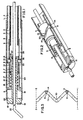
- Figure 1 is a sectional view of the distal end of the apparatus according to one embodiment of the present invention.
- Figure 2 is an isometric view of the distal end of the embodiment of the invention of Fig. 1.
- Figure 3 is an illustration of the wave-shaped groove which shows the cutouts that determine the direction of the rotation of the distal piston.
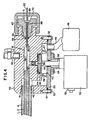
- Figure 4 is a cross sectional view of the proximal end of the apparatus according to one embodiment of the present invention.
- Figure 5 is a cross sectional view of an alternate embodiment of the distal end of the apparatus of the present invention.
- Figure 6 is a cross sectional view of an alternate embodiment of the proximal end of the apparatus of the present invention.
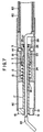
- Figure 7 is a sectional view of an alternative embodiment of the distal end of the apparatus in which the guide wire is of the fixed wire system type.
- distal end the end of the catheter, which is designed to be inserted into the patient's body
- proximal end The other end, which is designed to remain outside a patient's body, shall be referred to as the "proximal end”.
- distal direction or the term “distally” shall indicate a general direction from the proximal end to the distal end
- proximal direction or “proximally” shall refer to an opposite direction.
- the present invention provides for a catheter device which includes a cutting head for removing intraluminal occlusions.
- the cutting head is reciprocally movable from a first position in which is it sheathed by or retracted in the end of a catheter tube, to a second position in which the cutting head extends beyond the end of the catheter tube.
- the cutting head In addition to being reciprocally movable, the cutting head simultaneously rotates as it is moved reciprocally.
- the simultaneous reciprocal and rotating movement of the cutting head may be achieved by application of fluid, e.g., gas or liquid, pressure directly on a piston to which the cutting head is attached. Upon application of the fluid pressure, this piston simultaneously reciprocates and rotates. This movement of the piston is directly transferred to the cutting head which is attached to the piston.
- fluid e.g., gas or liquid
- the fluid pressure is pulsatile and the movement of the cutting head to the first or sheathed position may be assisted by means of a spring biasing force.
- the fluid pressure which acts on the distal piston is applied by another piston (to be referred to as the pressure piston) located at the proximal end of the catheter tube, which is connected to a reciprocating drive unit.
- the two above mentioned pistons move in unison. While pushing the pressure piston proximally, the pressure in the tube rises, resulting in movement of the distal piston in the same direction. Simultaneously, the distal piston undergoes a rotational movement as well, due to a wave-shaped groove located in its body, which is forced to rotate over stationary pins. As the pressure piston retracts proximally the pressure in the tube is reduced and the distal piston is forced to move proximally both by a spring force and by the vacuum created in the tube. Simultaneously, the distal piston and cutting head rotate in the same manner as explained above. This combined motion facilitates cutting of the occlusive material in the vessel.
- the present invention provides means to remove tissue debris from the site at which the cutting head cuts an object, e.g., an occlusion.
- removed debris is removed through an annular passage in the catheter. This annular passage is created when the above mentioned tube through which fluid pressure is applied to the distal piston is concentrically located inside another outer tube.
- a third piston (referred to below as the suction piston), located in the proximal end of the catheter device, or by a vacuum cylinder, or by an equivalent suction pump.
- tissue debris is removed by collecting the debris in a collection chamber which is located between the cutting head and the distal piston.
- the cutting head can be positioned in a first sheathed or retracted position.
- the cutting head When inserting and moving the distal end of the catheter in a patient, the cutting head is maintained in the first sheathed or retracted position in order to ensure safe passage and prevention of vessel perforation.
- Figs 1-3 depict the distal end of the catheter according to one embodiment of the present invention.
- the catheter comprises an outer flexible tube 1.
- Concentrically positioned within outer tube 1 is an inner tube 2, which if desired can be provided, with a braided reinforcement 3.
- An annular passage 4 is defined between outer tube 1 and inner tube 2.
- the distal end of outer tube 1 is located in a jacket 5.
- a cylinder 6 is concentrically located in jacket 5.
- Cylinder 6 contacts jacket 5 only by a plurality of protrusions 8 at its distal end and a plurality of protrusions 9 at its proximal end.
- the plurality of protrusions 8 and 9 are discrete and are spaced evenly around the outer circumference of cylinder 6. Because spacings are provided between adjacent protrusions, an open annular passage 10 is defined between cylinder 6 and jacket 5. As discussed below, passage 10 enables removal of blood and tissue debris.
- Inner tube 2 is connected at its distal end to cylinder 6.
- a distal piston 7 is housed within cylinder 6.
- Distal piston 7 is driven by fluid 28 applied through inner tube 2.
- a sealing means (e.g., O-ring) 11 at the distal end of distal piston 7 provides fluid-tight seal between the inner tube 2 and chamber 12.
- the pressure of fluid 28, which originates at the proximal end of the apparatus, fluctuates. The manner in which the pressure fluctuates will be discussed below with reference to Fig. 4.
- distal piston 7 As the pressure of fluid 28 rises in inner tune 2 distal piston 7 is forced distally in a rotational movement.
- the rotational movement of distal piston 7 is effected the presence of a closed wave-shaped groove 13 formed in the outer circumferential surface of distal piston 7.
- the movement of distal piston 7 is directed by one or more stationary pins 14, which are assembled in cylinder 6 and protrude into wave-shaped groove 13.
- the pattern of closed wave-shape groove 13 may vary according to the number of pins 14, and according to the desired ratio of reciprocating to rotational movement.
- distal piston 7 is pushed proximally by spring means 15 and drawn by a vacuum created in inner tube 2. Simultaneously, piston 7 undergoes a rotational movement in the same way as previously described. That is, by the cooperating action of the wave-shape groove 13 and stationary pins 14.
- a cutting head 16 is housed within jacket 5.
- the cutting head 16 has a stem 17 which passes through a central hole 18 in cylinder 6 and is connected to distal piston 7.
- the distal section of cutting head 16 has one or more cutting blades 19. Blood and tissue debris which are removed by the cutting head are drained to chamber 20 via openings 21 in cutting head 16 (Fig. 2). Because the cutting head 16 is connected to distal piston 7 it follows the same rotatory and reciprocating motion as distal piston 7. This combined movement facilitates the incision of an occlusion.
- Figs. 1 and 2 the cutting head 16 is shown at its most distal location.
- spring 15 forces cutting head 16 to move proximally so that it is concealed in jacket 5. This manner of concealing the cutting head 16 ensures that no injury will be caused to lumenal walls during insertion of the catheter into and patient's vessel.
- the manner in which piston 7 rotates in a predetermined direction is explained with reference to Fig. 3 below.
- a guide wire 22 extends distally in front of cutting head 16 for guiding the catheter through a patient's vessel.
- Guide wire 22 passes through inner tube 2 all the way up to the proximal end.
- guide wire 22 passes through hole 23 in distal piston 7 and through hole 24 in stem 17.
- guide wire 22 can be shorter and its proximal end can be connected to the inner circumference of cylinder 6.
- the guide wire as shown in Figs. 1 and 5, can extend through the catheter device.
- the guide wire can be of the fixed wire system type as shown in Fig. 7 in which one end of the guide wire 22 is fixed to the housing 81 of the catheter device.
- a sealing means is provided for forming a fluid-tight seal between guide wire 22 and distal piston 7.
- the sealing means e.g., O-ring
- O-ring 25 is mounted in recess 26 and is held in place by a retaining ring 27.
- Fig. 3 depicts the way in which piston 7 is rotated in a predetermined direction.
- Fig. 3 the development of closed wave-shaped groove 13 is shown.
- Dashed lines 1-1 and 2-2 represent the same spatial line.
- the wave-shaped groove 13 is longitudinally symmetrical and thus has no effect on the direction of rotation of distal piston 7. Sloped cutouts 30 and 31 determine the direction of rotation.
- Proximal movement of distal piston 7 is equivalent to a rightward movement of closed wave-shaped groove 13 in Fig. 3.
- This movement is equivalent to a counter-clock wise (CCW) rotation of distal piston 7 (when viewed proximally).
- CCW counter-clock wise
- Distal movement of distal piston 7 also will result in the same CCW rotation due to similar reasoning but this time it will encounter cutouts 30 rather than cutouts 31.
- the direction of rotation is dependent on the slope direction of cutouts 30 and 31. The effect causes reciprocating movement of distal piston 7 in a continuous CCW rotation.
- Fig. 4 shows the proximal end of the apparatus according to one embodiment of the present invention.
- the proximal end provides several functions:
- outer tube 1 and inner tube 2 are connected to support block 40 which may generally have a rectangular shape.
- annular passage 4 is defined between outer tube 1 and inner tube 2.
- Annular passage 4 serves for transferring blood and tissue debris from the distal end of the catheter to the proximal end thereof. As shown, passage 4 is opened to chamber 41.
- a duct 42 connects chamber 41 and chamber 43.
- aspiration at the distal end of the catheter is performed when suction piston 44 moves upwards.
- Sealing means e.g., O-ring 45 maintains the vacuum in chamber 43.
- check valve 46 is opened and simultaneously check valve 47 is closed causing aspiration of blood and tissue debris from the distal end of the catheter into chamber 43.
- suction piston 44 moves downwards.
- check valve 46 is closed and check valve 47 is opened thus forcing out blood and tissue debris from chamber 43 into removable collecting bag 48 via tube 49.
- opening 42 and chamber 43 are closed with plate 50.
- Plate 50 contains sealing means (e.g., elastic gasket) 51 and is assembled to block 40 with screws 52.
- Reciprocating drive unit 53 is fastened to plate 50 with screws 54.
- the drive unit 53 can be of any type that provides reciprocating motion e.g., linear actuator, crank mechanism, etc.
- Drive unit 53 is connected to suction piston 44 via rod 56, which passes through sealing means (e.g., O-ring) 57.
- Drive unit 53 is operated by switch 55.
- a pressure piston 58 having a sealing means (e.g., O-ring) 59 is connected to rod 56, which is a part of drive unit 53.
- the reciprocating movement of drive unit 53 and the attached pressure piston 58 produces pressure fluctuations. These pressure fluctuations are transferred via opening 60, chamber 61, and inner tube 2 to distal piston 7. Fluid 28 can be added to inner tube 2 if desired via opening 62 and valve 63.
- Block 40 contains another opening 64 through which guide wire 22 passes.
- a sealing means (e.g., O-ring) 65 is located in recess 66 and forms a fluid-tight seal between block 40 and guide wire 22. Pressure on sealing means 65 is maintained by threaded fitting 67.
- Guide wire 22 passes through opening 68 and through chucks 69, that are part of fixing nut 70. Tightening fixing nut 70 squeezes chucks 69 against tapered recess 71 and against guide wire 22 thus preventing guide wire 22 from moving.
- Fig. 5 depicts an alternate embodiment of the distal end of the catheter.
- the basic idea of this embodiment is similar to the one described in Figs. 1-3.
- the difference between the two embodiments is the way in which tissue debris are removed from the occlusion site.
- debris are aspirated via the catheter to the proximal end.
- debris are collected into a collecting chamber located next to the cutting head and removed from the collection chamber after the catheter is removed from the patient.
- the catheter comprises a tube 80, which if desired can be provided with a braided reinforcement 83.
- the distal part of tube 80 is located in housing 81.
- a distal piston 7 is housed within housing 81.
- Distal piston 7 is driven by fluid 28 which is applied through tube 80.
- a sealing means (e.g., O-ring) 11 at the distal end of distal piston 7 provides fluid-tight seal between tube 80 and chamber 12.
- the pressure of fluid 28, which originates at the proximal end of the apparatus fluctuates. The way the pressure fluctuates will be discussed below with reference to Fig. 6.
- distal piston 7 As the fluid pressure rises in tube 80 distal piston 7 is forced distally in a rotational movement.
- the rotation is effected by the presence of a closed wave-shaped groove 13 formed in the outer circumferential surface of distal piston 7.
- the movement of distal piston 7 is directed by one or more stationary pins 14, assembled in housing 81 which protrude into wave-shaped groove 13.
- the pattern of closed wave-shape groove 13 may vary according to the number of pins 14, and according to the desired ratio of reciprocating to rotational movement.
- distal piston 7 is pushed proximally by spring means 15 and drawn by a vacuum created in tube 80. Simultaneously, piston 7 undergoes a rotational movement in the same way as previously described.
- a cutting head 16 is located within housing 81.
- Cutting head 16 has a stem 17 that passes through a central hole 18 in housing 80 and is connected to distal piston 7.
- the distal section of cutting head 16 has one or more cutting blades 19. Blood and tissue debris are drained via opening 21 in cutting head 16 and stored in chamber 82.
- Cutting head 16 is connected to distal piston 7 and therefore follows the same rotatory and reciprocating motion as distal piston 7. This combined movement facilitates an incision of the occlusion.
- Fig. 5 the cutting head 16 is shown at its most distal location.
- spring 15 forces cutting head 16 to move proximally so that it is concealed in housing 81. This manner of concealing the cutting head ensures that no injury will be caused during insertion of the catheter into a patient's vessel.
- the way in which piston 7 rotates in a predetermined direction is explained above in reference to Fig. 3.
- a guide wire 22 extends distally in front of cutting head 16 for guiding the catheter through a patient's vessel.
- Guide wire 22 passes through tube 80 all the way up to the proximal end.
- the distal end of guide wire 22 passes through hole 23 in distal piston 7 and through hole 24 in stem 17.
- guide wire 22 can be shorter and its proximal end can be connected to the inner circumference of housing 81.
- a sealing means is provided for forming a fluid-tight seal between guide wire 22 and distal piston 7.
- the sealing means (e.g., O-ring) 25 is mounted in recess 26 and is held in place by a retaining ring 27.
- Fig. 6 shows an alternate proximal end of the apparatus.
- the proximal end shown in Fig. 6 provides two functions:
- a syringe pump 91 is fixed to housing of drive unit 96 by bracket 95 and clamp 92.
- the syringe piston 90 is connected to rod 94 via bracket 93.
- Rod 94 is a part of drive unit 96 which moves in a reciprocating movement.
- the drive unit 96 can be of any type that provides reciprocating motion e.g., linear actuator, crank mechanism, etc. The speed and direction of this movement is controlled by drive unit 96.
- Drive unit 96 is operated by switch 97.
- the movement of syringe piston 96 produces fluctuating pressure in fluid 28. This pressure is transferred to the distal end of the catheter via tube 80.
- the proximal end of the catheter also contains a T-shaped or branched fitting 98.
- Guide wire 22 passes through one opening in fitting 98.
- a sealing means 65 is located in recess 66 and forms a fluid-tight seal between block support fitting 98 and guide wire 22. Pressure on sealing means 65 (e.g., O-ring) is maintained by fitting 67.
- Guide wire 22 passes through opening 68 and through chucks 69, that are part of fixing nut 70. Tightening fixing nut 70 squeezes chucks 69 against tapered recess 71 and against guide wire 22 thus preventing guide wire 22 from moving.
- the materials from which the various elements of this catheter are constructed can be selected from known materials which are conventionally utilized in catheters.
- the braided reinforcement elements noted above likewise can be constructed from woven or laminated strands of known materials such as nylon.
Description
Claims (17)
- A device for removal of intra-luminal occlusions from a patient, the device comprising:characterised in that said means for moving the piston comprises, in combination, a closed wave-shaped groove (13) formed either in a circumferential surface of the piston or in an interior surface of the distal end of the catheter, and a pin (14) projecting from the other of the said two surfaces and which is received by the groove.a catheter (1) having a longitudinal axis, a distal end for insertion into the patient, and a proximal end;a piston (7) located within the distal end of the catheter for simultaneous longitudinal and rotational movement therein;means for simultaneously moving the piston longitudinally and reciprocally within the catheter and, in response to the longitudinal and reciprocal movement, rotating the piston about said longitudinal axis; anda cutting head (16) attached to the piston for simultaneous longitudinal and rotational movement together with the piston;
- A device according to claim 1, wherein the closed wave-shaped groove is formed in a circumferential surface of the piston, and the pin projects from an interior surface of the catheter.
- A device according to claim 1, wherein the closed wave-shaped groove is formed in an interior surface of the catheter and the pin projects from the circumferential surface of the piston.
- A device according to any of claims 1 to 3, wherein at one position of its longitudinal motion the cutting head is within the distal end of the catheter, and at another position the cutting head extends beyond the distal end of the catheter.
- A device according to any preceding claim, wherein the cutting head comprises at least one cutting blade (19).
- A device according to any preceding claim, wherein the catheter includes a chamber (20) for receiving material cut by the cutting head, the chamber being located between the piston and the cutting head, and the cutting head having a bore (21) therethrough for the passage of material into the chamber.
- A device according to claim 6, wherein the chamber is connected by a passage to the proximal end of the catheter.
- A device according to any preceding claim, wherein the catheter includes a guide wire (12) which extends through the piston and the cutting head.
- A device according to claim 8 , wherein the guide wire extends beyond the distal end of the catheter.
- A device according to claim 8, wherein the catheter includes a branched fitting (98) near its proximal end and the guide wire enters the catheter through that branched fitting.
- A device according to claim 10, wherein the branched fitting comprises means (69,70,71) to secure the guide wire.
- A device according to any preceding claim, wherein pump means (58) is provided at the proximal end of the catheter for applying fluid pressure to the piston for driving said piston.
- A device according to claim 12, wherein the pump means comprises a reciprocating pump means.
- A device according to claim 13, wherein the pump means comprises dual pumping means both for applying fluid pressure to the piston and for applying a vacuum to aspirate material cut by the cutting means.
- A device according to claim 14, wherein the pump means comprises a single piston to perform said dual pumping.
- A device according to any of claims 12 to 15, wherein the pump means comprises a chamber for collecting cut material.
- A device according to any of claims 12 to 16, wherein the pump means is attached to a support block (40) through which a guide wire passes, the support block preferably comprising means (69,70,71) to secure the guide wire.
Applications Claiming Priority (1)
| Application Number | Priority Date | Filing Date | Title |
|---|---|---|---|
| PCT/US1994/003439 WO1995027443A1 (en) | 1994-04-07 | 1994-04-07 | Device for removal of intraluminal occlusions |
Publications (3)
| Publication Number | Publication Date |
|---|---|
| EP0746245A1 EP0746245A1 (en) | 1996-12-11 |
| EP0746245A4 EP0746245A4 (en) | 1997-11-19 |
| EP0746245B1 true EP0746245B1 (en) | 2002-11-20 |
Family
ID=22242398
Family Applications (1)
| Application Number | Title | Priority Date | Filing Date |
|---|---|---|---|
| EP94916513A Expired - Lifetime EP0746245B1 (en) | 1994-04-07 | 1994-04-07 | Device for removal of intraluminal occlusions |
Country Status (6)
| Country | Link |
|---|---|
| EP (1) | EP0746245B1 (en) |
| JP (1) | JP3466620B2 (en) |
| AU (1) | AU686165B2 (en) |
| CA (1) | CA2162881C (en) |
| DE (1) | DE69431760T2 (en) |
| WO (1) | WO1995027443A1 (en) |
Cited By (13)
| Publication number | Priority date | Publication date | Assignee | Title |
|---|---|---|---|---|
| US7727178B2 (en) | 2001-12-03 | 2010-06-01 | Ekos Corporation | Catheter with multiple ultrasound radiating members |
| US7774933B2 (en) | 2002-02-28 | 2010-08-17 | Ekos Corporation | Method of manufacturing ultrasound catheters |
| US7914509B2 (en) | 1997-05-01 | 2011-03-29 | Ekos Corporation | Ultrasound catheter |
| US7976483B2 (en) | 1997-05-01 | 2011-07-12 | Ekos Corporation | Ultrasound assembly with increased efficacy |
| US8192363B2 (en) | 2006-10-27 | 2012-06-05 | Ekos Corporation | Catheter with multiple ultrasound radiating members |
| US8226629B1 (en) | 2002-04-01 | 2012-07-24 | Ekos Corporation | Ultrasonic catheter power control |
| WO2014028046A1 (en) * | 2012-08-17 | 2014-02-20 | Laurimed, Llc | Devices and methods for cutting tissue |
| US8657842B2 (en) | 2010-06-30 | 2014-02-25 | Laurimed, Llc | Devices and methods for cutting tissue |
| US8764700B2 (en) | 1998-06-29 | 2014-07-01 | Ekos Corporation | Sheath for use with an ultrasound element |
| US8815099B1 (en) | 2014-01-21 | 2014-08-26 | Laurimed, Llc | Devices and methods for filtering and/or collecting tissue |
| US8840632B2 (en) | 2010-06-30 | 2014-09-23 | Laurimed, Llc | Devices and methods for cutting tissue |
| WO2022130368A1 (en) * | 2020-12-14 | 2022-06-23 | Carevature Medical Ltd. | Pneumatic-based tissue debulking devices |
| US11672553B2 (en) | 2007-06-22 | 2023-06-13 | Ekos Corporation | Method and apparatus for treatment of intracranial hemorrhages |
Families Citing this family (24)
| Publication number | Priority date | Publication date | Assignee | Title |
|---|---|---|---|---|
| US6406442B1 (en) | 1996-11-07 | 2002-06-18 | Prolifix Medical, Inc. | Guidewire for precision catheter positioning |
| US6371928B1 (en) | 1997-11-07 | 2002-04-16 | Prolifix Medical, Inc. | Guidewire for positioning a catheter against a lumen wall |
| US6139557A (en) * | 1997-11-07 | 2000-10-31 | Prolifix Medical, Inc. | Apparatus for making wire with radial expansible guide section and methods of manufacturing the same |
| US6007497A (en) * | 1998-06-30 | 1999-12-28 | Ethicon Endo-Surgery, Inc. | Surgical biopsy device |
| WO2000002478A2 (en) * | 1998-07-10 | 2000-01-20 | Micro Medical Devices, Inc. | Hydraulic surgical system |
| US20080146965A1 (en) | 2003-08-11 | 2008-06-19 | Salvatore Privitera | Surgical Device for The Collection of Soft Tissue |
| US20010047183A1 (en) | 2000-04-05 | 2001-11-29 | Salvatore Privitera | Surgical device for the collection of soft tissue |
| US6086544A (en) * | 1999-03-31 | 2000-07-11 | Ethicon Endo-Surgery, Inc. | Control apparatus for an automated surgical biopsy device |
| US6120462A (en) * | 1999-03-31 | 2000-09-19 | Ethicon Endo-Surgery, Inc. | Control method for an automated surgical biopsy device |
| EP1992308B1 (en) | 1999-06-02 | 2015-10-28 | Microtransform, Inc. | Intracorporeal occlusive device |
| US6511493B1 (en) * | 2000-01-10 | 2003-01-28 | Hydrocision, Inc. | Liquid jet-powered surgical instruments |
| US6942627B2 (en) | 2001-07-19 | 2005-09-13 | Ethicon Endo-Surgery, Inc. | Surgical biopsy device having a flexible cutter |
| JP4373745B2 (en) * | 2003-09-12 | 2009-11-25 | Hoya株式会社 | Endoscopy forceps |
| US10182833B2 (en) | 2007-01-08 | 2019-01-22 | Ekos Corporation | Power parameters for ultrasonic catheter |
| EP2234562B1 (en) | 2007-12-21 | 2019-02-27 | MicroVention, Inc. | A system and method of detecting implant detachment |
| JP5366974B2 (en) | 2007-12-21 | 2013-12-11 | マイクロベンション インコーポレイテッド | System and method for determining the position of a separation zone of a separable implant |
| US8206316B2 (en) * | 2009-06-12 | 2012-06-26 | Devicor Medical Products, Inc. | Tetherless biopsy device with reusable portion |
| KR20130054952A (en) | 2010-04-14 | 2013-05-27 | 마이크로벤션, 인코포레이티드 | Implant delivery device |
| US11458290B2 (en) | 2011-05-11 | 2022-10-04 | Ekos Corporation | Ultrasound system |
| US9770289B2 (en) | 2012-02-10 | 2017-09-26 | Myromed, Llc | Vacuum powered rotary devices and methods |
| CN104955407B (en) * | 2012-11-13 | 2018-11-06 | 约翰·克拉芬布克 | Medical instrument |
| US10092742B2 (en) | 2014-09-22 | 2018-10-09 | Ekos Corporation | Catheter system |
| EP3307388B1 (en) | 2015-06-10 | 2022-06-22 | Ekos Corporation | Ultrasound catheter |
| DE102019206871B4 (en) * | 2019-05-07 | 2023-07-20 | Geuder Ag | Device for cutting and aspirating tissue from the human or animal eye |
Family Cites Families (10)
| Publication number | Priority date | Publication date | Assignee | Title |
|---|---|---|---|---|
| DE1117258B (en) * | 1959-10-19 | 1961-11-16 | Medizintechnik Leipzig Veb | Sample excision device |
| US4316465A (en) * | 1979-03-30 | 1982-02-23 | Dotson Robert S Jun | Ophthalmic handpiece with pneumatically operated cutter |
| US4678459A (en) * | 1984-07-23 | 1987-07-07 | E-Z-Em, Inc. | Irrigating, cutting and aspirating system for percutaneous surgery |
| EP0310685A1 (en) * | 1985-11-22 | 1989-04-12 | Kontron-Holding Ag | Angioplasty catheter |
| US4669469A (en) * | 1986-02-28 | 1987-06-02 | Devices For Vascular Intervention | Single lumen atherectomy catheter device |
| US4749376A (en) * | 1986-10-24 | 1988-06-07 | Intravascular Surgical Instruments, Inc. | Reciprocating working head catheter |
| US4923462A (en) * | 1987-03-17 | 1990-05-08 | Cordis Corporation | Catheter system having a small diameter rotatable drive member |
| DE3801318A1 (en) * | 1988-01-19 | 1989-07-27 | Stocksmeier Uwe | MEDICAL CATHETER WITH CUTTER |
| US4895560A (en) * | 1988-03-31 | 1990-01-23 | Papantonakos Apostolos C | Angioplasty apparatus |
| DE9116000U1 (en) * | 1991-07-05 | 1992-04-23 | Klass, Willibald, 3451 Dielmissen, De |
-
1994
- 1994-04-07 AU AU68140/94A patent/AU686165B2/en not_active Ceased
- 1994-04-07 EP EP94916513A patent/EP0746245B1/en not_active Expired - Lifetime
- 1994-04-07 CA CA002162881A patent/CA2162881C/en not_active Expired - Fee Related
- 1994-04-07 JP JP52629795A patent/JP3466620B2/en not_active Expired - Fee Related
- 1994-04-07 DE DE69431760T patent/DE69431760T2/en not_active Expired - Lifetime
- 1994-04-07 WO PCT/US1994/003439 patent/WO1995027443A1/en active IP Right Grant
Cited By (22)
| Publication number | Priority date | Publication date | Assignee | Title |
|---|---|---|---|---|
| US7976483B2 (en) | 1997-05-01 | 2011-07-12 | Ekos Corporation | Ultrasound assembly with increased efficacy |
| US8690818B2 (en) | 1997-05-01 | 2014-04-08 | Ekos Corporation | Ultrasound catheter for providing a therapeutic effect to a vessel of a body |
| US7914509B2 (en) | 1997-05-01 | 2011-03-29 | Ekos Corporation | Ultrasound catheter |
| US8764700B2 (en) | 1998-06-29 | 2014-07-01 | Ekos Corporation | Sheath for use with an ultrasound element |
| US8167831B2 (en) | 2001-12-03 | 2012-05-01 | Ekos Corporation | Catheter with multiple ultrasound radiating members |
| US7727178B2 (en) | 2001-12-03 | 2010-06-01 | Ekos Corporation | Catheter with multiple ultrasound radiating members |
| US7828762B2 (en) | 2001-12-03 | 2010-11-09 | Ekos Corporation | Catheter with multiple ultrasound radiating members |
| US8696612B2 (en) | 2001-12-03 | 2014-04-15 | Ekos Corporation | Catheter with multiple ultrasound radiating members |
| US9415242B2 (en) | 2001-12-03 | 2016-08-16 | Ekos Corporation | Catheter with multiple ultrasound radiating members |
| US7774933B2 (en) | 2002-02-28 | 2010-08-17 | Ekos Corporation | Method of manufacturing ultrasound catheters |
| US8852166B1 (en) | 2002-04-01 | 2014-10-07 | Ekos Corporation | Ultrasonic catheter power control |
| US8226629B1 (en) | 2002-04-01 | 2012-07-24 | Ekos Corporation | Ultrasonic catheter power control |
| US8192363B2 (en) | 2006-10-27 | 2012-06-05 | Ekos Corporation | Catheter with multiple ultrasound radiating members |
| US11672553B2 (en) | 2007-06-22 | 2023-06-13 | Ekos Corporation | Method and apparatus for treatment of intracranial hemorrhages |
| US8657842B2 (en) | 2010-06-30 | 2014-02-25 | Laurimed, Llc | Devices and methods for cutting tissue |
| US8840632B2 (en) | 2010-06-30 | 2014-09-23 | Laurimed, Llc | Devices and methods for cutting tissue |
| US8882793B2 (en) | 2010-06-30 | 2014-11-11 | Laurimed, Llc | Devices and methods for cutting tissue |
| US9532796B2 (en) | 2010-06-30 | 2017-01-03 | Myromed, Llc | Devices and methods for cutting tissue |
| AU2013303222B2 (en) * | 2012-08-17 | 2017-10-12 | Myromed, Llc | Devices and methods for cutting tissue |
| WO2014028046A1 (en) * | 2012-08-17 | 2014-02-20 | Laurimed, Llc | Devices and methods for cutting tissue |
| US8815099B1 (en) | 2014-01-21 | 2014-08-26 | Laurimed, Llc | Devices and methods for filtering and/or collecting tissue |
| WO2022130368A1 (en) * | 2020-12-14 | 2022-06-23 | Carevature Medical Ltd. | Pneumatic-based tissue debulking devices |
Also Published As
| Publication number | Publication date |
|---|---|
| EP0746245A4 (en) | 1997-11-19 |
| WO1995027443A1 (en) | 1995-10-19 |
| AU686165B2 (en) | 1998-02-05 |
| JP3466620B2 (en) | 2003-11-17 |
| AU6814094A (en) | 1995-10-30 |
| EP0746245A1 (en) | 1996-12-11 |
| DE69431760T2 (en) | 2003-10-02 |
| CA2162881A1 (en) | 1995-10-19 |
| JPH10503385A (en) | 1998-03-31 |
| CA2162881C (en) | 2006-03-28 |
| DE69431760D1 (en) | 2003-01-02 |
Similar Documents
| Publication | Publication Date | Title |
|---|---|---|
| EP0746245B1 (en) | Device for removal of intraluminal occlusions | |
| US5350390A (en) | Device for removal of intraluminal occlusions | |
| US8568332B2 (en) | Biopsy apparatus | |
| AU651950B2 (en) | Improved distal atherectomy catheter | |
| US4994067A (en) | Distal atherectomy catheter | |
| US5431673A (en) | Distal atherectomy catheter | |
| US4696667A (en) | Intravascular catheter and method | |
| US4728319A (en) | Intravascular catheter | |
| US6152894A (en) | Surgical cutting instrument | |
| US6066153A (en) | Device and method for resecting body tissues | |
| US4108182A (en) | Reciprocation vitreous suction cutter head | |
| US5112299A (en) | Arthroscopic surgical apparatus and method | |
| EP0426322B1 (en) | Fiber tip atherectomy catheter | |
| EP0316085B1 (en) | Surgical cutting instrument | |
| US5116350A (en) | Catheter system having distal tip for opening obstructions | |
| EP3777701B1 (en) | Biopsy rotary cutting device | |
| CN110151259B (en) | Electrified tissue resection device | |
| EP0809970B1 (en) | Medical material removal instrumentation | |
| CN111658074B (en) | Reciprocating type thrombus and plaque excision device | |
| CN115153750A (en) | Mechanical thrombectomy device and use method | |
| Frost et al. | The design and development of an irrigating sucking cutter for neurosurgical use |
Legal Events
| Date | Code | Title | Description |
|---|---|---|---|
| PUAI | Public reference made under article 153(3) epc to a published international application that has entered the european phase |
Free format text: ORIGINAL CODE: 0009012 |
|
| 17P | Request for examination filed |
Effective date: 19951221 |
|
| AK | Designated contracting states |
Kind code of ref document: A1 Designated state(s): BE DE ES FR GB IT NL |
|
| A4 | Supplementary search report drawn up and despatched |
Effective date: 19970929 |
|
| AK | Designated contracting states |
Kind code of ref document: A4 Designated state(s): BE DE ES FR GB IT NL |
|
| 17Q | First examination report despatched |
Effective date: 20010214 |
|
| GRAG | Despatch of communication of intention to grant |
Free format text: ORIGINAL CODE: EPIDOS AGRA |
|
| GRAG | Despatch of communication of intention to grant |
Free format text: ORIGINAL CODE: EPIDOS AGRA |
|
| GRAH | Despatch of communication of intention to grant a patent |
Free format text: ORIGINAL CODE: EPIDOS IGRA |
|
| GRAH | Despatch of communication of intention to grant a patent |
Free format text: ORIGINAL CODE: EPIDOS IGRA |
|
| GRAA | (expected) grant |
Free format text: ORIGINAL CODE: 0009210 |
|
| AK | Designated contracting states |
Kind code of ref document: B1 Designated state(s): BE DE ES FR GB IT NL |
|
| PG25 | Lapsed in a contracting state [announced via postgrant information from national office to epo] |
Ref country code: NL Free format text: LAPSE BECAUSE OF FAILURE TO SUBMIT A TRANSLATION OF THE DESCRIPTION OR TO PAY THE FEE WITHIN THE PRESCRIBED TIME-LIMIT Effective date: 20021120 Ref country code: IT Free format text: LAPSE BECAUSE OF FAILURE TO SUBMIT A TRANSLATION OF THE DESCRIPTION OR TO PAY THE FEE WITHIN THE PRE;WARNING: LAPSES OF ITALIAN PATENTS WITH EFFECTIVE DATE BEFORE 2007 MAY HAVE OCCURRED AT ANY TIME BEFORE 2007. THE CORRECT EFFECTIVE DATE MAY BE DIFFERENT FROM THE ONE RECORDED.SCRIBED TIME-LIMIT Effective date: 20021120 Ref country code: BE Free format text: LAPSE BECAUSE OF FAILURE TO SUBMIT A TRANSLATION OF THE DESCRIPTION OR TO PAY THE FEE WITHIN THE PRESCRIBED TIME-LIMIT Effective date: 20021120 |
|
| REG | Reference to a national code |
Ref country code: GB Ref legal event code: FG4D |
|
| REF | Corresponds to: |
Ref document number: 69431760 Country of ref document: DE Date of ref document: 20030102 |
|
| NLV1 | Nl: lapsed or annulled due to failure to fulfill the requirements of art. 29p and 29m of the patents act | ||
| PG25 | Lapsed in a contracting state [announced via postgrant information from national office to epo] |
Ref country code: ES Free format text: LAPSE BECAUSE OF FAILURE TO SUBMIT A TRANSLATION OF THE DESCRIPTION OR TO PAY THE FEE WITHIN THE PRESCRIBED TIME-LIMIT Effective date: 20030529 |
|
| ET | Fr: translation filed | ||
| PLBE | No opposition filed within time limit |
Free format text: ORIGINAL CODE: 0009261 |
|
| STAA | Information on the status of an ep patent application or granted ep patent |
Free format text: STATUS: NO OPPOSITION FILED WITHIN TIME LIMIT |
|
| 26N | No opposition filed |
Effective date: 20030821 |
|
| PGFP | Annual fee paid to national office [announced via postgrant information from national office to epo] |
Ref country code: GB Payment date: 20100325 Year of fee payment: 17 |
|
| PGFP | Annual fee paid to national office [announced via postgrant information from national office to epo] |
Ref country code: FR Payment date: 20100521 Year of fee payment: 17 |
|
| PGFP | Annual fee paid to national office [announced via postgrant information from national office to epo] |
Ref country code: DE Payment date: 20100426 Year of fee payment: 17 |
|
| REG | Reference to a national code |
Ref country code: DE Ref legal event code: R119 Ref document number: 69431760 Country of ref document: DE |
|
| REG | Reference to a national code |
Ref country code: DE Ref legal event code: R119 Ref document number: 69431760 Country of ref document: DE |
|
| GBPC | Gb: european patent ceased through non-payment of renewal fee |
Effective date: 20110407 |
|
| REG | Reference to a national code |
Ref country code: FR Ref legal event code: ST Effective date: 20111230 |
|
| PG25 | Lapsed in a contracting state [announced via postgrant information from national office to epo] |
Ref country code: FR Free format text: LAPSE BECAUSE OF NON-PAYMENT OF DUE FEES Effective date: 20110502 |
|
| PG25 | Lapsed in a contracting state [announced via postgrant information from national office to epo] |
Ref country code: GB Free format text: LAPSE BECAUSE OF NON-PAYMENT OF DUE FEES Effective date: 20110407 |
|
| PG25 | Lapsed in a contracting state [announced via postgrant information from national office to epo] |
Ref country code: DE Free format text: LAPSE BECAUSE OF NON-PAYMENT OF DUE FEES Effective date: 20111031 |