EP0750915A2 - Tip protection device - Google Patents
Tip protection device Download PDFInfo
- Publication number
- EP0750915A2 EP0750915A2 EP96304187A EP96304187A EP0750915A2 EP 0750915 A2 EP0750915 A2 EP 0750915A2 EP 96304187 A EP96304187 A EP 96304187A EP 96304187 A EP96304187 A EP 96304187A EP 0750915 A2 EP0750915 A2 EP 0750915A2
- Authority
- EP
- European Patent Office
- Prior art keywords
- cannula
- safety cover
- tip
- axial channel
- retracted
- Prior art date
- Legal status (The legal status is an assumption and is not a legal conclusion. Google has not performed a legal analysis and makes no representation as to the accuracy of the status listed.)
- Granted
Links
Images


Classifications
-
- A—HUMAN NECESSITIES
- A61—MEDICAL OR VETERINARY SCIENCE; HYGIENE
- A61M—DEVICES FOR INTRODUCING MEDIA INTO, OR ONTO, THE BODY; DEVICES FOR TRANSDUCING BODY MEDIA OR FOR TAKING MEDIA FROM THE BODY; DEVICES FOR PRODUCING OR ENDING SLEEP OR STUPOR
- A61M25/00—Catheters; Hollow probes
- A61M25/01—Introducing, guiding, advancing, emplacing or holding catheters
- A61M25/06—Body-piercing guide needles or the like
- A61M25/0612—Devices for protecting the needle; Devices to help insertion of the needle, e.g. wings or holders
- A61M25/0618—Devices for protecting the needle; Devices to help insertion of the needle, e.g. wings or holders having means for protecting only the distal tip of the needle, e.g. a needle guard
-
- A—HUMAN NECESSITIES
- A61—MEDICAL OR VETERINARY SCIENCE; HYGIENE
- A61M—DEVICES FOR INTRODUCING MEDIA INTO, OR ONTO, THE BODY; DEVICES FOR TRANSDUCING BODY MEDIA OR FOR TAKING MEDIA FROM THE BODY; DEVICES FOR PRODUCING OR ENDING SLEEP OR STUPOR
- A61M5/00—Devices for bringing media into the body in a subcutaneous, intra-vascular or intramuscular way; Accessories therefor, e.g. filling or cleaning devices, arm-rests
- A61M5/178—Syringes
- A61M5/31—Details
- A61M5/32—Needles; Details of needles pertaining to their connection with syringe or hub; Accessories for bringing the needle into, or holding the needle on, the body; Devices for protection of needles
- A61M5/3205—Apparatus for removing or disposing of used needles or syringes, e.g. containers; Means for protection against accidental injuries from used needles
- A61M5/321—Means for protection against accidental injuries by used needles
- A61M5/3243—Means for protection against accidental injuries by used needles being axially-extensible, e.g. protective sleeves coaxially slidable on the syringe barrel
- A61M5/3245—Constructional features thereof, e.g. to improve manipulation or functioning
- A61M2005/3247—Means to impede repositioning of protection sleeve from needle covering to needle uncovering position
- A61M2005/325—Means obstructing the needle passage at distal end of a needle protection sleeve
-
- A—HUMAN NECESSITIES
- A61—MEDICAL OR VETERINARY SCIENCE; HYGIENE
- A61M—DEVICES FOR INTRODUCING MEDIA INTO, OR ONTO, THE BODY; DEVICES FOR TRANSDUCING BODY MEDIA OR FOR TAKING MEDIA FROM THE BODY; DEVICES FOR PRODUCING OR ENDING SLEEP OR STUPOR
- A61M5/00—Devices for bringing media into the body in a subcutaneous, intra-vascular or intramuscular way; Accessories therefor, e.g. filling or cleaning devices, arm-rests
- A61M5/178—Syringes
- A61M5/31—Details
- A61M5/32—Needles; Details of needles pertaining to their connection with syringe or hub; Accessories for bringing the needle into, or holding the needle on, the body; Devices for protection of needles
- A61M5/3205—Apparatus for removing or disposing of used needles or syringes, e.g. containers; Means for protection against accidental injuries from used needles
- A61M5/321—Means for protection against accidental injuries by used needles
- A61M5/3243—Means for protection against accidental injuries by used needles being axially-extensible, e.g. protective sleeves coaxially slidable on the syringe barrel
- A61M5/3273—Means for protection against accidental injuries by used needles being axially-extensible, e.g. protective sleeves coaxially slidable on the syringe barrel freely sliding on needle shaft without connection to syringe or needle
Definitions
- the present invention relates generally to stick prevention apparatus for protecting medical personnel from injury. More particularly, the present invention relates to tip covering elements having internal conformations which prevent a retracted needle from reemerging therethrough.
- Medical care of individuals in hospitals, clinics, and other health care facilities often includes the taking of blood samples, intravenous supplying of medication, and the introduction or removal of other fluids via cannulae, needles, or syringes.
- the present medical environment in which there exist diseases, for example Acquired Immune Deficiency Syndrome, AIDS, for which there are no cures, and which are transmitted via blood to blood contact, has raised concerns relating to the potential for contaminated "needle sticks".
- U.S. Patent No. 5,215,528 to Purdy et al. (hereinafter Purdy) teaches an assembly for introducing a catheter into a blood vessel, wherein there is provided a tip cover which includes an elastically deforming L-shaped.
- the L-shaped member In an initial disposition, the L-shaped member is positioned in a deformed state with the cannula inserted fully through the cover. Once the cannula is retracted, however, the L-shaped member springs into a position to prevent reemergence of the needle. Manual repositioning of the L-shaped member is necessary to permit the cannula reemerge from the cover.
- U.S. Patent 5,127,905 to Lemieux teaches a protection cap, which is similar to the device disclosed by Purdy, as described above.
- an externally mounted rotating L-shaped lever is disposed along the axis of the cover, manual actuation of which by a user once the cannula is retracted prevents the cannula from re-emerging from the cover.
- Manual retraction of the external L-shaped lever from the path of the cannula permits the cannula to reemerge.
- U.S. Patent 4,826,490 to Byrne et al. (hereinafter Byrne) teaches a safety cover and syringe assembly wherein an external cylindrical sleeve, through which the cannula extends, is slidably mounted to a track on the external surface of the syringe. Sliding the external cylindrical sleeve relative to the cannula and the syringe, such that the cannula is fully retracted into the sleeve, causes a locking mechanism to engage between the syringe and the sleeve so that the cannula may not be advanced out of the sleeve without disengagement of the locking elements by a user.
- U.S. Patent 4,952,207 which is also to Lemieux.
- This reference teaches a safety cover for use with a cannula which has a radial notch along the shaft, near the tip.
- the internal structure of the cover includes a tab which 1 engages the cannula in the notch once the cannula has been retracted. Rotation of the cannula, or the safety cover locks the cannula in position and prevents its reemergence.
- the Lemieux prevention means may be compromised by intentional, or random, manipulation of the device. While each device includes functional means for preventing "needle sticks" by interfering with the exposure of a cannula once it is retracted into a cover, it is of considerable concern for users of such devices that, if a means for disengaging the retaining element is provided, random forces may expose the contaminated cannula, thus presenting a danger to medical personnel. This concern is especially applicable to the variety of "needle stick" prevention devices which include externally mounted prevention means.
- the present invention is directed to a needle cover which includes an axial channel and an interior chamber, through which a cannula may extend. Along this axial channel and/or in the interior chamber, there is provided means for permitting unidirectional translation of a cannula.
- the cannula In an initial disposition, the cannula is fully inserted through the safety cover, with the cannula extending through the axial channel. After the cannula has been used and has become contaminated, the cannula is retracted (or the cover is advanced along the shaft of the cannula) such that the tip is fully within the cover. Once freed from the influence of the cannula, the means for permitting only unidirectional movement are engaged to prevent the cannula from reemerging from the cover.
- a cylindrical safety cover comprises an axial through hole which extends along the elongate axis thereof.
- the axial through hole includes a forward portion, the surface of which comprises a plurality of reverse angled semi-flexible bristle members which permit the cannula to translate back into the cover. Once the cannula is 1 retracted, however, the bristles block the axial channel and the forward translation of the cannula is prevented.
- the axial channel is provided with a slight curvature, and the surface of the 5 channel is ribbed.
- the cover itself is constructed of a semi-flexible and quasi-elastomeric material such that, in an initial disposition, the cannula may be inserted fully through the axial channel. After use, the cannula is retracted along the axial channel until the tip of the cannula is fully within the channel. Without the linear influence of the cannula shaft to prevent the channel from restoring itself, the channel regains its ideal curvate alignment. Attempts to advance the cannula, once the channel has regained its curvate alignment, cause the sharp tip of the cannula to dig into the side wall of the channel. This is especially effective if the channel surface is ribbed, therein providing a substantial lip for the tip to dig into.
- a similar cover element having an axial channel therethrough, but also including an interior chamber.
- a spring plate having a forward engaging edge and pair of through holes therein, is mounted to the rear wall of the interior chamber.
- the forward engaging edge is forcibly held against the shaft of the cannula such that the through holes are aligned with the axial channel.
- the cannula is therefore provided a linear path along which to translate.
- the forward engaging edge of the spring is released.
- the expansion of the spring forward causes the through holes therein to become partially misaligned, therein gripping the shaft of the cannula.
- the cannula is thereby prevented from advancing by the grip of the holes in the spring plate as well as the forward engaging edge which is positioned in front of the axial channel, thus preventing the advance of the cannula.
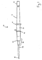
- Figure 1 is a side view of a medical assembly including a catheter, a cannula, a syringe, and the safety cover of the present invention.
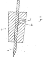
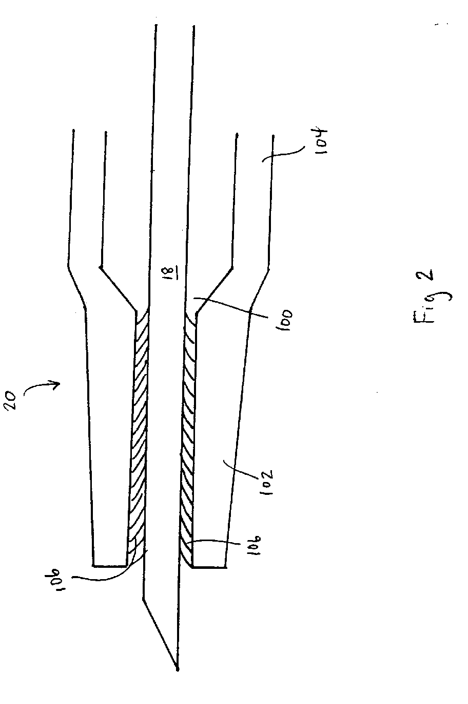
- Figure 2 is a side cross-section view of one aspect of the present invention including a plurality of reverse angle bristles, with the cannula in its initial position.
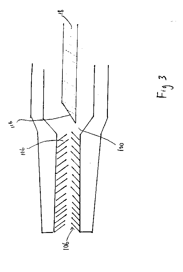
- Figure 3 is a side cross-section view of the aspect of the present invention shown in Figure 2, wherein the cannula has been retracted and the reverse angle bristles prevent the advance of the cannula.
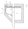
- Figure 4 is a side cross-section view of another aspect of the present invention including a ribbed curvate axial channel, with the cannula in its initial position.
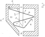
- Figure 5 in a side cross-section view of the aspect of the present invention shown in Figure 4, wherein the cannula has been retracted and subsequently partially advanced into the ribbed curvate channel.
- Figure 6 is a side cross-section view of an aspect of the present invention including a spring plate, disposed in its initial compressed position with the cannula positioned therethrough.
- Figure 7 is a side cross-section view of the aspect of the present invention shown in Figure 6, wherein the cannula has been retracted and spring plate has advanced, thereby preventing the cannula from advancing.
- FIG. 1 shows a catheter insertion apparatus 10 having a safety cover 20.
- the apparatus 10 which is shown in a side view, includes a syringe body 12, with an annular ring 14 at the base thereof, and a standard slidable plunger element 16 which translates within the syringe body 12.
- a cannula 18 extends axially outward from the annular ring 14; the narrow hollow internal passage within the cannula 18 providing a connection from the internal volume of the syringe body 12 to the exterior, through which fluids may flow.
- the cannula 18 extends outward from the annular ring 14, through a safety cover 20.
- the safety cover 20, is constructed so that the cannula 18 may be inserted axially therethrough and so that the cannula 18 and the safety cover 20 may be translated relative to each other.
- the apparatus 10 further includes a catheter 25.
- the catheter 25 includes an elongate narrow, flexible, tube section 24, through which the cannula 18 is disposed prior to the catheter being inserted into the patient.
- the catheter 25 further includes a hub 22 having a widened receiving port 26, in which a portion of the safety cover 20 is initially nested. The nested portion 21 of the safety cover 20 is shown in phantom.
- the cannula 18 therefore extends outward from the annular ring 14 of the syringe body 12, sequentially through the safety in which the safety cover 20 is initially nested, the widened receiving port 26 of the catheter hub 22, and ultimately through the elongate narrow flexible tube section 24.
- the cannula 18 is disposed through the narrow flexible tube section 24, to enable puncturing and insertion of the flexible tube 24 through the skin of a patient, and positioning of the tube 24 into the desired blood vessel. If properly positioned in the blood vessel, the user withdraws the cannula 18 from the patient without removing the catheter element 22, therein providing an open conduit through which the medical care provider may draw blood, or input appropriate medication directly to the vasculature.
- the receiving port 26 of the catheter element 22 and the external surface of the safety cover 20 are releasably mated in the initial disposition of the apparatus 10.
- the safety cover 20 and the receiving port 26 remain coupled until the tip of the cannula 18 is fully retracted into the safety cover 20. Once the tip of the cannula 18 is fully retracted, the safety cover 20 is released from the catheter element 22.
- a variety of mechanisms for releasably holding the safety cover 20 to the receiving port 26 of the catheter hub 22 are shown in the art, any one of which may be employed in the present assembly.
- Such releasable couplings may be manually actuatable or automatically actuated by the retraction of the tip of the cannula 18.
- the cover comprises an elongate and generally cylindrical body having an axial channel 100, which extends from the forward portion 102, to a rearward portion 104.
- the portion of the axial channel 100 which extends through the forward portion 102 of the safety cover includes a plurality of flexible reverse angled bristles 106 which are angled and biased to allow movement of the tip inward to retract the tip into the cover, but to prevent reentry of the tip into the forward portion of the axial channel 100.
- the bristles 106 may comprise, for example plastic flashes or metal spikes.
- the cannula 18 causes the bristles 106 to be radially deflected radially as 1 shown in Figure 2 (the curved back sweep of the bristles 106).
- FIG. 3 a side cross-section view of the apparatus shown in Figure 2 is provided, wherein the tip of the cannula 18 has been retracted. As is shown, the retraction of the tip 116 of the cannula 18 beyond the forward portion of the axial channel 100 necessarily frees the bristles 106 from the compressive influence of the cannula 18. Once freed from the axial alignment provided by the shaft of the cannula 18, the bristles 106 spring back into position and effectively block the forward translation of the cannula through that portion of the channel 100.
- the axial channel 100 is formed of a resilient and semi-flexible material, for example a moldable thermoplastic, having a slight curvature, and the interior surface comprising a plurality of ribbings 208.
- the cannula extends fully through the slightly curved axial channel, thereby imparting a straightening force to the channel 100.
- the disposition of the cannula 18 with respect to the axial channel 200 is shown wherein the tip 116 of the cannula has been retracted into the channel, and subsequently forced forward.
- the shaft thereof no longer provides a straightening influence to the axial channel 200. Without the straightening influence, the resilient and semi-flexible character of the cover material permits the channel 200 to regain its original slightly curvate shape.
- the cannula 18 includes a sharp tip 116, and is not constructed of a similarly semi-flexible material (cannulae are generally constructed of surgical steel or other suitably rigid metal), attempted reinsertion of the cannula 18 through the axial channel 200 causes the tip 116 to dig into the side wall surface thereof.
- the ribbings 208 of the side wall surface of the axial channel 200 provide particularly ideal sites for the tip 116 to catch and dig.
- ribbings 208 or bristles 106 utilized is an engineering expedient which does not alter the teachings of the present invention in any way. It is entirely anticipated that one may chose to include ribbings or bristles of any suitable length, depth, shape, size, or depth which are sufficient to prevent reinsertion of the cannula 18.
- FIG. 6 a side cross-section view of a third embodiment of the present invention is provided, wherein the safety cover 60 is shown having the cannula 18 in its initial, fully inserted position through the axial channel 62.
- a cover element 60 is provided, having a linear axial channel 62 therethrough which includes an interior chamber 64.
- a spring plate 66 having a forward engaging edge 68 and pair of through holes 70a,70b therein, is mounted to the rear wall 72 of the interior chamber 64.
- the 1 spring 66 is compressed by virtue of the fact that the forward engaging edge 68 is forced upward to rest against the shaft of the cannula 18.
- the through holes 70a,70b of the spring plate 66 are aligned under the compression described above.
- the cannula 18 is therefore provided a linear path along which to translate.
- the forward edge 68 moves into a blocking position in front of the forward portion of the axial channel 62 of the safety cover.
- the cannula 18 is thereby prevented from advancing by the grip of the holes 70a,70b in the spring plate 66 as well as the forward engaging edge 68 which is positioned in front of the axial channel 62, thus preventing the advance of the cannula.
Abstract

Description
- The present invention relates generally to stick prevention apparatus for protecting medical personnel from injury. More particularly, the present invention relates to tip covering elements having internal conformations which prevent a retracted needle from reemerging therethrough.
- Medical care of individuals in hospitals, clinics, and other health care facilities often includes the taking of blood samples, intravenous supplying of medication, and the introduction or removal of other fluids via cannulae, needles, or syringes. The present medical environment, in which there exist diseases, for example Acquired Immune Deficiency Syndrome, AIDS, for which there are no cures, and which are transmitted via blood to blood contact, has raised concerns relating to the potential for contaminated "needle sticks".
- A wide variety of devices have been provided in the prior art for prevention against accidental contaminated "needle sticks". For example, U.S. Patent No. 5,215,528 to Purdy et al. (hereinafter Purdy) teaches an assembly for introducing a catheter into a blood vessel, wherein there is provided a tip cover which includes an elastically deforming L-shaped. In an initial disposition, the L-shaped member is positioned in a deformed state with the cannula inserted fully through the cover. Once the cannula is retracted, however, the L-shaped member springs into a position to prevent reemergence of the needle. Manual repositioning of the L-shaped member is necessary to permit the cannula reemerge from the cover.
- U.S. Patent 5,127,905 to Lemieux teaches a protection cap, which is similar to the device disclosed by Purdy, as described above. In the Lemieux device an externally mounted rotating L-shaped lever is disposed along the axis of the cover, manual actuation of which by a user once the cannula is retracted prevents the cannula from re-emerging from the cover. Manual retraction of the external L-shaped lever from the path of the cannula permits the cannula to reemerge.
- U.S. Patent 4,826,490 to Byrne et al. (hereinafter Byrne) teaches a safety cover and syringe assembly wherein an external cylindrical sleeve, through which the cannula extends, is slidably mounted to a track on the external surface of the syringe. Sliding the external cylindrical sleeve relative to the cannula and the syringe, such that the cannula is fully retracted into the sleeve, causes a locking mechanism to engage between the syringe and the sleeve so that the cannula may not be advanced out of the sleeve without disengagement of the locking elements by a user.
- A device, which is similar to the one disclosed in the Byrne reference, is U.S. Patent 4,952,207 which is also to Lemieux. This reference teaches a safety cover for use with a cannula which has a radial notch along the shaft, near the tip. The internal structure of the cover includes a tab which 1 engages the cannula in the notch once the cannula has been retracted. Rotation of the cannula, or the safety cover locks the cannula in position and prevents its reemergence.
- As above, however, the Lemieux prevention means may be compromised by intentional, or random, manipulation of the device. While each device includes functional means for preventing "needle sticks" by interfering with the exposure of a cannula once it is retracted into a cover, it is of considerable concern for users of such devices that, if a means for disengaging the retaining element is provided, random forces may expose the contaminated cannula, thus presenting a danger to medical personnel. This concern is especially applicable to the variety of "needle stick" prevention devices which include externally mounted prevention means.
- It is, therefore, a principal object of the present invention to provide a needle cover which includes an element or elements which prevent exposure of a contaminated cannula.
- It is further an object of the present invention to provide a needle cover which cannot be compromised, whereby the cannula may reemerge therethrough, by application of random environmental forces, or by unintentional manipulation of the device.
- It is further an object of the present invention to provide a needle cover which is more reliable in its safety aspects.
- other objects and advantages of the invention will be more fully apparent from the ensuing disclosure and appended claims.
- The present invention is directed to a needle cover which includes an axial channel and an interior chamber, through which a cannula may extend. Along this axial channel and/or in the interior chamber, there is provided means for permitting unidirectional translation of a cannula. In an initial disposition, the cannula is fully inserted through the safety cover, with the cannula extending through the axial channel. After the cannula has been used and has become contaminated, the cannula is retracted (or the cover is advanced along the shaft of the cannula) such that the tip is fully within the cover. Once freed from the influence of the cannula, the means for permitting only unidirectional movement are engaged to prevent the cannula from reemerging from the cover.
- A variety of embodiments of the present invention are contemplated, including reverse angled bristles, a notched (or ribbed) and curved internal channel, and interlocking spring elements. More specifically, in a first embodiment, a cylindrical safety cover comprises an axial through hole which extends along the elongate axis thereof. The axial through hole includes a forward portion, the surface of which comprises a plurality of reverse angled semi-flexible bristle members which permit the cannula to translate back into the cover. Once the cannula is 1 retracted, however, the bristles block the axial channel and the forward translation of the cannula is prevented.
- In a second embodiment, the axial channel is provided with a slight curvature, and the surface of the 5 channel is ribbed. The cover itself is constructed of a semi-flexible and quasi-elastomeric material such that, in an initial disposition, the cannula may be inserted fully through the axial channel. After use, the cannula is retracted along the axial channel until the tip of the cannula is fully within the channel. Without the linear influence of the cannula shaft to prevent the channel from restoring itself, the channel regains its ideal curvate alignment. Attempts to advance the cannula, once the channel has regained its curvate alignment, cause the sharp tip of the cannula to dig into the side wall of the channel. This is especially effective if the channel surface is ribbed, therein providing a substantial lip for the tip to dig into.
- In a third embodiment, a similar cover element is provided, having an axial channel therethrough, but also including an interior chamber. A spring plate, having a forward engaging edge and pair of through holes therein, is mounted to the rear wall of the interior chamber. In an initial disposition, the forward engaging edge is forcibly held against the shaft of the cannula such that the through holes are aligned with the axial channel. The cannula is therefore provided a linear path along which to translate. After use, however, once the cannula is retracted through the axial channel, and backed into the interior chamber, the forward engaging edge of the spring is released. The expansion of the spring forward causes the through holes therein to become partially misaligned, therein gripping the shaft of the cannula. The cannula is thereby prevented from advancing by the grip of the holes in the spring plate as well as the forward engaging edge which is positioned in front of the axial channel, thus preventing the advance of the cannula.
- Figure 1 is a side view of a medical assembly including a catheter, a cannula, a syringe, and the safety cover of the present invention.
- Figure 2 is a side cross-section view of one aspect of the present invention including a plurality of reverse angle bristles, with the cannula in its initial position.
- Figure 3 is a side cross-section view of the aspect of the present invention shown in Figure 2, wherein the cannula has been retracted and the reverse angle bristles prevent the advance of the cannula.
- Figure 4 is a side cross-section view of another aspect of the present invention including a ribbed curvate axial channel, with the cannula in its initial position.
- Figure 5 in a side cross-section view of the aspect of the present invention shown in Figure 4, wherein the cannula has been retracted and subsequently partially advanced into the ribbed curvate channel.
- Figure 6 is a side cross-section view of an aspect of the present invention including a spring plate, disposed in its initial compressed position with the cannula positioned therethrough.
- Figure 7 is a side cross-section view of the aspect of the present invention shown in Figure 6, wherein the cannula has been retracted and spring plate has advanced, thereby preventing the cannula from advancing.
- This invention relates to the field of hypodermic needles and most particularly to devices for inserting catheters into blood vessels. Referring now to the drawings, Figure 1 shows a
catheter insertion apparatus 10 having asafety cover 20. Theapparatus 10, which is shown in a side view, includes asyringe body 12, with an annular ring 14 at the base thereof, and a standardslidable plunger element 16 which translates within thesyringe body 12. Acannula 18 extends axially outward from the annular ring 14; the narrow hollow internal passage within thecannula 18 providing a connection from the internal volume of thesyringe body 12 to the exterior, through which fluids may flow. - The
cannula 18 extends outward from the annular ring 14, through asafety cover 20. Thesafety cover 20, is constructed so that thecannula 18 may be inserted axially therethrough and so that thecannula 18 and thesafety cover 20 may be translated relative to each other. In the embodiment shown in Figure 1, theapparatus 10 further includes acatheter 25. Thecatheter 25 includes an elongate narrow, flexible,tube section 24, through which thecannula 18 is disposed prior to the catheter being inserted into the patient. Thecatheter 25 further includes ahub 22 having a widened receivingport 26, in which a portion of thesafety cover 20 is initially nested. The nested portion 21 of thesafety cover 20 is shown in phantom. Thecannula 18 therefore extends outward from the annular ring 14 of thesyringe body 12, sequentially through the safety in which thesafety cover 20 is initially nested, the widened receivingport 26 of thecatheter hub 22, and ultimately through the elongate narrowflexible tube section 24. - In use the
cannula 18 is disposed through the narrowflexible tube section 24, to enable puncturing and insertion of theflexible tube 24 through the skin of a patient, and positioning of thetube 24 into the desired blood vessel. If properly positioned in the blood vessel, the user withdraws thecannula 18 from the patient without removing thecatheter element 22, therein providing an open conduit through which the medical care provider may draw blood, or input appropriate medication directly to the vasculature. - The process of removing cannulae from patients and decoupling syringes and cannulae from their corresponding catheter elements, in apparatus of the prior art, exposed the medical care providers to the sharp tip of the cannula which had been contaminated by the patient's blood. In the present invention, the receiving
port 26 of thecatheter element 22 and the external surface of thesafety cover 20 are releasably mated in the initial disposition of theapparatus 10. During extraction of thesyringe 10 andcannula 18, thesafety cover 20 and the receivingport 26 remain coupled until the tip of thecannula 18 is fully retracted into thesafety cover 20. Once the tip of thecannula 18 is fully retracted, thesafety cover 20 is released from thecatheter element 22. A variety of mechanisms for releasably holding thesafety cover 20 to the receivingport 26 of thecatheter hub 22 are shown in the art, any one of which may be employed in the present assembly. Such releasable couplings may be manually actuatable or automatically actuated by the retraction of the tip of thecannula 18. - Referring now to Figure 2, a side cross-section view of a first embodiment of the
safety cover 20 of the present invention is provided wherein thecannula 18 andsafety cover 20 are illustrated in their initial, pre-insertion, disposition in which thecannula 18 extends axially through thesafety cover 20. More specifically, the cover comprises an elongate and generally cylindrical body having anaxial channel 100, which extends from theforward portion 102, to arearward portion 104. The portion of theaxial channel 100 which extends through theforward portion 102 of the safety cover includes a plurality of flexible reverseangled bristles 106 which are angled and biased to allow movement of the tip inward to retract the tip into the cover, but to prevent reentry of the tip into the forward portion of theaxial channel 100. Thebristles 106 may comprise, for example plastic flashes or metal spikes. In the initial position, thecannula 18 causes thebristles 106 to be radially deflected radially as 1 shown in Figure 2 (the curved back sweep of the bristles 106). - Referring now to Figure 3, a side cross-section view of the apparatus shown in Figure 2 is provided, wherein the tip of the
cannula 18 has been retracted. As is shown, the retraction of the tip 116 of thecannula 18 beyond the forward portion of theaxial channel 100 necessarily frees thebristles 106 from the compressive influence of thecannula 18. Once freed from the axial alignment provided by the shaft of thecannula 18, thebristles 106 spring back into position and effectively block the forward translation of the cannula through that portion of thechannel 100. - Referring now to Figures 4 and 5, a second embodiment of the present invention is provided in cross-section views showing the
cannula 18 and thesafety cover 40 in the initial and retracted positions, respectively. More particularly with respect to Figure 4, theaxial channel 100 is formed of a resilient and semi-flexible material, for example a moldable thermoplastic, having a slight curvature, and the interior surface comprising a plurality ofribbings 208. In this initial position, the cannula extends fully through the slightly curved axial channel, thereby imparting a straightening force to thechannel 100. - Referring, in particular, to Figure 5, the disposition of the
cannula 18 with respect to theaxial channel 200 is shown wherein the tip 116 of the cannula has been retracted into the channel, and subsequently forced forward. Once thecannula 18 is retracted into thecover 40, the shaft thereof no longer provides a straightening influence to theaxial channel 200. Without the straightening influence, the resilient and semi-flexible character of the cover material permits thechannel 200 to regain its original slightly curvate shape. Inasmuch as thecannula 18 includes a sharp tip 116, and is not constructed of a similarly semi-flexible material (cannulae are generally constructed of surgical steel or other suitably rigid metal), attempted reinsertion of thecannula 18 through theaxial channel 200 causes the tip 116 to dig into the side wall surface thereof. Theribbings 208 of the side wall surface of theaxial channel 200 provide particularly ideal sites for the tip 116 to catch and dig. - It is understood that the number of
ribbings 208 or bristles 106 utilized is an engineering expedient which does not alter the teachings of the present invention in any way. It is entirely anticipated that one may chose to include ribbings or bristles of any suitable length, depth, shape, size, or depth which are sufficient to prevent reinsertion of thecannula 18. - Referring now to Figures 6 and 7, a side cross-section view of a third embodiment of the present invention is provided, wherein the
safety cover 60 is shown having thecannula 18 in its initial, fully inserted position through the axial channel 62. With respect to Figure 6, acover element 60 is provided, having a linear axial channel 62 therethrough which includes aninterior chamber 64. A spring plate 66, having a forward engaging edge 68 and pair of through holes 70a,70b therein, is mounted to therear wall 72 of theinterior chamber 64. In an initial disposition, the 1 spring 66 is compressed by virtue of the fact that the forward engaging edge 68 is forced upward to rest against the shaft of thecannula 18. The through holes 70a,70b of the spring plate 66 are aligned under the compression described above. Thecannula 18 is therefore provided a linear path along which to translate. - Referring now to Figure 7, after the
cannula 18 has been used, it is retracted through the axial channel, and the tip 116 is drawn back beyond the forward engaging edge 68 of the spring 66. Once the positioning influence of thecannula 18 is removed, the edge 68 and spring 66, are permitted to advance downward and forward. The expansion of the spring 66 causes the through holes to move relative to the axial channel 62 of the safety cover, therein becoming partially misaligned. In this partially misaligned position, the rims 71a,71b of the through holes 70a,70b, respectively, grip the shaft of thecannula 18, locking the cannula in position. In addition, the forward edge 68 moves into a blocking position in front of the forward portion of the axial channel 62 of the safety cover. Thecannula 18 is thereby prevented from advancing by the grip of the holes 70a,70b in the spring plate 66 as well as the forward engaging edge 68 which is positioned in front of the axial channel 62, thus preventing the advance of the cannula. - While there has been described and illustrated specific safety covers for preventing accidental "needle sticks" with contaminated needles, it will be apparent to those skilled in the art that variations and modifications are possible without deviating from the broad spirit and principle of the present invention which shall be limited solely by the scope of the claims appended hereto.
Claims (7)
- A safety cover for locking a tip of a cannula therein, comprising:an elongate body having an interior chamber, said elongate body being slidably mountable on said cannula;an axial channel, extending along the entire axial length of the elongate body, from a forward portion of the body, to a rearward portion, said axial channel slidably receiving therethrough the cannula; andmeans disposed in said axial channel which displaces upon retraction of the tip of said cannula, whereby subsequent advancement of said cannula fully through said safety cover is prevented.
- The safety cover set forth in claim 1, wherein said means comprises a plurality of bristles which are angled and biased to allow movement of the tip inward to retract into the cover, but which bristles prevent reentry of the tip into the forward portion.
- The safety cover set forth in claim 2, wherein said bristles comprise plastic flashes.
- The safety cover set forth in claim 2, wherein said bristles comprise metal spikes.
- The safety cover set forth in claim 1, wherein said forward portion of said elongate body comprises a resilient semi-flexible material having a curvate bias, whereby the axial channel displaces upon retraction of said cannula, thereby preventing tip advancement therethrough.
- The safety cover set forth in claim 5, wherein said axial channel further comprises a plurality of radial ribs.
- A safety cover for locking a tip of a cannula therein, comprising:an elongate body having an interior chamber, slidably mountable on said cannula;an axial channel extending along the entire axial length of the elongate body, from a forward portion of the body, through said interior chamber and through a rearward portion, said cannula being slidable therethrough; anda spring plate fixably mounted to a rear surface of said interior chamber, said spring plate having a pair of through holes for receiving said cannula therethrough when said spring is compressed, and a forward engaging edge which is engaged by said cannula to hold the spring in a compressed position, such that the retraction of the tip of said cannula causes the forward engaging edge and the through holes to displace, thereby preventing subsequent advancement of said cannula fully through said safety cover.
Priority Applications (2)
| Application Number | Priority Date | Filing Date | Title |
|---|---|---|---|
| EP04076807A EP1462136B1 (en) | 1995-06-07 | 1996-06-06 | Tip protection device |
| EP00200949A EP1027903B1 (en) | 1995-06-07 | 1996-06-06 | Tip protection device |
Applications Claiming Priority (2)
| Application Number | Priority Date | Filing Date | Title |
|---|---|---|---|
| US482588 | 1995-06-07 | ||
| US08/482,588 US5882337A (en) | 1995-06-07 | 1995-06-07 | Tip protection device |
Related Child Applications (2)
| Application Number | Title | Priority Date | Filing Date |
|---|---|---|---|
| EP00200949A Division EP1027903B1 (en) | 1995-06-07 | 1996-06-06 | Tip protection device |
| EP04076807A Division EP1462136B1 (en) | 1995-06-07 | 1996-06-06 | Tip protection device |
Publications (3)
| Publication Number | Publication Date |
|---|---|
| EP0750915A2 true EP0750915A2 (en) | 1997-01-02 |
| EP0750915A3 EP0750915A3 (en) | 1997-02-05 |
| EP0750915B1 EP0750915B1 (en) | 2004-09-22 |
Family
ID=23916654
Family Applications (3)
| Application Number | Title | Priority Date | Filing Date |
|---|---|---|---|
| EP00200949A Expired - Lifetime EP1027903B1 (en) | 1995-06-07 | 1996-06-06 | Tip protection device |
| EP96304187A Expired - Lifetime EP0750915B1 (en) | 1995-06-07 | 1996-06-06 | Tip protection device |
| EP04076807A Expired - Lifetime EP1462136B1 (en) | 1995-06-07 | 1996-06-06 | Tip protection device |
Family Applications Before (1)
| Application Number | Title | Priority Date | Filing Date |
|---|---|---|---|
| EP00200949A Expired - Lifetime EP1027903B1 (en) | 1995-06-07 | 1996-06-06 | Tip protection device |
Family Applications After (1)
| Application Number | Title | Priority Date | Filing Date |
|---|---|---|---|
| EP04076807A Expired - Lifetime EP1462136B1 (en) | 1995-06-07 | 1996-06-06 | Tip protection device |
Country Status (6)
| Country | Link |
|---|---|
| US (1) | US5882337A (en) |
| EP (3) | EP1027903B1 (en) |
| JP (1) | JP3805434B2 (en) |
| DE (3) | DE69637741D1 (en) |
| ES (3) | ES2227570T3 (en) |
| TW (1) | TW485825U (en) |
Cited By (28)
| Publication number | Priority date | Publication date | Assignee | Title |
|---|---|---|---|---|
| US6595955B2 (en) | 2001-03-15 | 2003-07-22 | Specialized Health Products, Inc. | Safety shield for medical needles |
| US6796962B2 (en) | 2001-03-15 | 2004-09-28 | Specialized Health Products, Inc. | Safety shield for medical needles |
| EP1509264A1 (en) * | 2002-06-06 | 2005-03-02 | Manan Medical Products, Inc. | Needle tip protector |
| WO2005042073A1 (en) * | 2003-10-31 | 2005-05-12 | Tyco Healthcare Group Lp | Safety shield |
| EP1807135A2 (en) * | 2004-09-28 | 2007-07-18 | B. Braun Medical, Inc. | Protective clips |
| US7264613B2 (en) | 1997-08-20 | 2007-09-04 | B. Braun Melsungen Ag | Spring clip safety IV catheter |
| WO2008104400A1 (en) * | 2007-03-01 | 2008-09-04 | Hans Haindl | Device for avoiding contact of a user of an injection needle with the tip of the injection needle after use |
| WO2009067646A1 (en) * | 2007-11-21 | 2009-05-28 | Becton, Dickinson And Company | Needle safety device |
| US7611487B2 (en) | 1997-08-20 | 2009-11-03 | B. Braun Melsungen Ag | Protective device for an injection needle |
| US7611499B2 (en) | 1997-08-20 | 2009-11-03 | B. Braun Melsungen Ag | Spring clip safety IV catheter |
| WO2011000570A1 (en) * | 2009-07-02 | 2011-01-06 | B. Braun Melsungen Ag | Protective device for an injection needle |
| US7963943B2 (en) | 2007-09-27 | 2011-06-21 | Tyco Healthcare Group Lp | I.V. catheter assembly and needle safety device |
| US7988664B2 (en) | 2004-11-01 | 2011-08-02 | Tyco Healthcare Group Lp | Locking clip with trigger bushing |
| US8096973B2 (en) | 2003-11-25 | 2012-01-17 | Specialized Health Products, Inc. | Resettable safety shield for medical needles |
| US8162904B2 (en) | 2006-03-29 | 2012-04-24 | Terumo Kabushiki Kaisha | Needle protector |
| US8357104B2 (en) | 2007-11-01 | 2013-01-22 | Coviden Lp | Active stylet safety shield |
| US8376994B2 (en) | 2001-02-26 | 2013-02-19 | B. Braun Melsungen Ag | Protective device for an injection needle |
| US8382721B2 (en) | 1997-08-20 | 2013-02-26 | B. Braun Melsungen Ag | Spring clip safety IV catheter |
| EP2298404B1 (en) * | 2002-06-20 | 2016-08-10 | Becton Dickinson and Company | Catheter and introducer needle assembly with needle shield |
| US9539398B2 (en) | 2001-03-15 | 2017-01-10 | Specialized Health Products, Inc. | Safety shield for medical needles |
| US9877771B2 (en) | 2009-09-10 | 2018-01-30 | Covidien Lp | System and method for power supply noise reduction |
| WO2018111816A3 (en) * | 2016-12-13 | 2019-01-31 | Becton, Dickinson And Company | Safety needle devices |
| US10589036B2 (en) | 2016-12-13 | 2020-03-17 | Becton, Dickinson And Company | Safety needle device |
| US10661026B2 (en) | 2016-12-13 | 2020-05-26 | Becton, Dickinson And Company | Safety needle device |
| US10814073B2 (en) | 2016-12-13 | 2020-10-27 | Becton, Dickinson And Company | Safety device with collapsible housing and trigger activation |
| US11103651B2 (en) | 2016-12-13 | 2021-08-31 | Beckon, Dickinson and Company | Safety needle devices |
| US11147910B2 (en) | 2016-12-12 | 2021-10-19 | Becton, Dickinson And Company | Packaging for safety needle |
| US11173253B2 (en) | 2016-12-12 | 2021-11-16 | Becton, Dickinson And Company | Packaging for safety needle |
Families Citing this family (45)
| Publication number | Priority date | Publication date | Assignee | Title |
|---|---|---|---|---|
| ATE481124T1 (en) * | 1996-02-27 | 2010-10-15 | Braun Melsungen Ag | NEEDLE TIP PROTECTION FOR SUBCUTANEOUS INJECTIONS |
| US6749588B1 (en) | 1998-04-09 | 2004-06-15 | Becton Dickinson And Company | Catheter and introducer needle assembly with needle shield |
| DE29921084U1 (en) * | 1999-12-01 | 2000-02-17 | Braun Melsungen Ag | Short catheter |
| CN1276781C (en) * | 2000-12-18 | 2006-09-27 | 泰尔茂株式会社 | Protector and storage needle assembly |
| US6585704B2 (en) | 2001-01-29 | 2003-07-01 | B. Braun Medical, Inc. | Method of retaining a tip protector on a needle with a curved tip |
| US7004927B2 (en) * | 2001-03-15 | 2006-02-28 | Specialized Health Products, Inc. | Safety shield for medical needles |
| US6902546B2 (en) | 2001-03-15 | 2005-06-07 | Specialized Health Products, Inc. | Safety shield for medical needles |
| US6984213B2 (en) * | 2001-03-15 | 2006-01-10 | Specialized Health Products, Inc. | Biopsy needle device |
| US7179244B2 (en) * | 2001-03-15 | 2007-02-20 | Specialized Health Products, Inc. | Resettable safety shield for medical needles |
| US6652486B2 (en) * | 2001-09-27 | 2003-11-25 | Medex, Inc. | Safety catheter |
| US6866648B2 (en) * | 2002-05-28 | 2005-03-15 | Macosta Medical U.S.A., L.L.C. | Method and apparatus to decrease the risk of intraneuronal injection during administration of nerve block anesthesia |
| ES2808602T3 (en) * | 2002-06-20 | 2021-03-01 | Becton Dickinson Co | Catheter and introducer needle assembly with needle guard |
| AU2003249349A1 (en) * | 2002-06-21 | 2004-01-06 | Becton Dickinson And Company | Method of and apparatus for controlling flashback in an introducer needle and catheter assembly |
| US20050043709A1 (en) * | 2002-10-10 | 2005-02-24 | Brimhall Greg L. | System and method of delivering local anesthesia |
| US7458954B2 (en) * | 2002-11-07 | 2008-12-02 | Specialized Health Products, Inc. | Safety shield for medical needles |
| MXPA06009272A (en) * | 2004-02-13 | 2007-02-02 | Smiths Medical Asd Inc | Needle tip protector. |
| US7513888B2 (en) * | 2004-02-17 | 2009-04-07 | Smiths Medical Asd, Inc. | Needle guards |
| US7850650B2 (en) | 2005-07-11 | 2010-12-14 | Covidien Ag | Needle safety shield with reset |
| US7828773B2 (en) | 2005-07-11 | 2010-11-09 | Covidien Ag | Safety reset key and needle assembly |
| US7905857B2 (en) | 2005-07-11 | 2011-03-15 | Covidien Ag | Needle assembly including obturator with safety reset |
| US20060276747A1 (en) | 2005-06-06 | 2006-12-07 | Sherwood Services Ag | Needle assembly with removable depth stop |
| US7731692B2 (en) | 2005-07-11 | 2010-06-08 | Covidien Ag | Device for shielding a sharp tip of a cannula and method of using the same |
| BRPI0614085A2 (en) * | 2005-08-08 | 2012-12-25 | Smiths Medical Asd Inc | safety catheter device, needle guards and needle guard clip, and generally consistent removal forces obtaining method of a duckbill release mechanism |
| US8162881B2 (en) * | 2005-08-08 | 2012-04-24 | Smiths Medical Asd, Inc. | Needle guard mechanism with angled strut wall |
| US20070038182A1 (en) * | 2005-08-08 | 2007-02-15 | Bialecki Dennis M | Needle guard mechanism with needle support |
| US8403886B2 (en) * | 2005-08-08 | 2013-03-26 | Smiths Medical Asd, Inc. | Needle guard clip with lip |
| US7654735B2 (en) | 2005-11-03 | 2010-02-02 | Covidien Ag | Electronic thermometer |
| DE102005058133A1 (en) * | 2005-11-30 | 2007-05-31 | Schott Ag | Syringe, has sealing element and syringe body whereby annular, flexible deformable area can be pressed in sealing manner, by means of closing cap, on outer surface of cannula |
| US20080033370A1 (en) * | 2006-08-03 | 2008-02-07 | Becton, Dickinson And Company | Binary needle attachment mechanisms |
| JP4994775B2 (en) | 2006-10-12 | 2012-08-08 | 日本コヴィディエン株式会社 | Needle point protector |
| NZ585524A (en) * | 2007-11-21 | 2013-03-28 | Becton Dickinson Co | A safety needle guard with a cannula passing through a multi slot aperture |
| EP2075029B1 (en) | 2007-12-20 | 2010-09-29 | Tyco Healthcare Group LP | Locking cap assembly with spring-loaded collar |
| US7785296B2 (en) * | 2008-07-17 | 2010-08-31 | Smiths Medical Asd, Inc. | Needle tip spring protector |
| ES2662356T3 (en) | 2011-04-27 | 2018-04-06 | Kpr U.S., Llc | Safety IV catheter assemblies |
| DE102011052878A1 (en) | 2011-08-21 | 2013-02-21 | Enrico Bahr | Disposable syringe for use with safety features, particularly for medical applications, has syringe body and syringe piston, where syringe body and plunger of syringe piston have triangular cross section with rounded corners |
| WO2013048975A1 (en) | 2011-09-26 | 2013-04-04 | Covidien Lp | Safety catheter |
| WO2013048768A1 (en) | 2011-09-26 | 2013-04-04 | Covidien Lp | Safety iv catheter and needle assembly |
| WO2013056223A1 (en) | 2011-10-14 | 2013-04-18 | Covidien Lp | Safety iv catheter assembly |
| US8414539B1 (en) | 2011-12-27 | 2013-04-09 | B. Braun Melsungen Ag | Needle tip guard for percutaneous entry needles |
| US10350366B2 (en) | 2013-02-01 | 2019-07-16 | Nxstage Medical, Inc. | Safe cannulation devices, methods, and systems |
| US9555221B2 (en) | 2014-04-10 | 2017-01-31 | Smiths Medical Asd, Inc. | Constant force hold tip protector for a safety catheter |
| US10980522B2 (en) | 2016-10-18 | 2021-04-20 | Piper Access, Llc | Intraosseous access devices, systems, and methods |
| WO2018165334A1 (en) | 2017-03-07 | 2018-09-13 | Piper Access, Llc. | Safety shields for elongated instruments and related systems and methods |
| CA3050963A1 (en) | 2017-03-10 | 2018-09-13 | Piper Access, Llc. | Securement devices, systems, and methods |
| EP3755247B1 (en) | 2018-02-20 | 2023-07-05 | Piper Access, LLC | Drilling devices and related methods |
Citations (6)
| Publication number | Priority date | Publication date | Assignee | Title |
|---|---|---|---|---|
| US3964480A (en) * | 1974-10-03 | 1976-06-22 | Froning Edward C | Apparatus for sterotaxic lateral extradural disc puncture |
| US4091811A (en) * | 1976-11-15 | 1978-05-30 | Baxter Travenol Laboratories, Inc. | Needle cover |
| US5098394A (en) * | 1990-05-31 | 1992-03-24 | Luther Ronald B | Biased shut off valve assembly for needle and catheter |
| US5348544A (en) * | 1993-11-24 | 1994-09-20 | Becton, Dickinson And Company | Single-handedly actuatable safety shield for needles |
| EP0639388A2 (en) * | 1993-08-17 | 1995-02-22 | Pere Arques-Teixidor | An intravascular puncturing nozzle with an automatic no blood reflux mechanism |
| WO1995028979A1 (en) * | 1994-04-20 | 1995-11-02 | Noble House Group Pty. Ltd. | Protective device |
Family Cites Families (39)
| Publication number | Priority date | Publication date | Assignee | Title |
|---|---|---|---|---|
| US4016842A (en) * | 1974-11-08 | 1977-04-12 | Kittler Milton J | Resilient throttle stop means |
| SE411516B (en) * | 1977-10-26 | 1980-01-14 | Reenstierna E G B | DEVICE FOR DESTRUCTION OF AN INJECTION SPRAYER |
| DE2929425A1 (en) * | 1979-07-20 | 1981-02-12 | Lothar Kling | DEVICE FOR INJECTION SYRINGES FOR INTRAMUSCULAR AND SUBENTANE INJECTION |
| GB8519049D0 (en) * | 1985-07-29 | 1985-09-04 | Bryne P O | Safety device |
| US4826490A (en) * | 1985-07-29 | 1989-05-02 | National Research Development Corporation | Safety device for hypodermic needle or the like |
| US4931048A (en) * | 1986-04-07 | 1990-06-05 | Icu Medical, Inc. | Medical device |
| US4762516A (en) * | 1987-03-05 | 1988-08-09 | Luther Medical Products, Inc. | Assembly of needle catheter protector |
| US4832696A (en) * | 1987-03-05 | 1989-05-23 | Luther Medical Products, Inc. | Assembly of needle and protector |
| US4804371A (en) * | 1987-05-06 | 1989-02-14 | Vaillancourt Vincent L | Post-injection needle sheath |
| US4944725A (en) * | 1987-06-01 | 1990-07-31 | Mcdonald Michael | Safety needle apparatus |
| US4834718A (en) * | 1987-06-01 | 1989-05-30 | Michael McDonald | Safety needle apparatus |
| US4790828A (en) * | 1987-08-07 | 1988-12-13 | Dombrowski Mitchell P | Self-capping needle assembly |
| US4950252A (en) * | 1987-11-02 | 1990-08-21 | Luther Medical Products, Inc. | Single hand actuated locking safety catheter and method of use |
| US5137515A (en) * | 1987-11-02 | 1992-08-11 | City Of Hope | Safety device for removal and disposal of medical needles |
| US5013305A (en) * | 1988-06-29 | 1991-05-07 | Opie Eric A | Needle safety system and method |
| US4952207A (en) * | 1988-07-11 | 1990-08-28 | Critikon, Inc. | I.V. catheter with self-locating needle guard |
| US4978344A (en) * | 1988-08-11 | 1990-12-18 | Dombrowski Mitchell P | Needle and catheter assembly |
| US4964854A (en) * | 1989-01-23 | 1990-10-23 | Luther Medical Products, Inc. | Intravascular catheter assembly incorporating needle tip shielding cap |
| AU649218B2 (en) * | 1989-02-01 | 1994-05-19 | Sero-Guard Corporation | Disposable automatic hypodermic needle guard |
| US4917669A (en) * | 1989-02-08 | 1990-04-17 | Safetyject | Catheter inserter |
| US5007901A (en) * | 1989-11-24 | 1991-04-16 | Shields Jack W | Intravenous catheter insertion device |
| US5205829A (en) * | 1990-02-09 | 1993-04-27 | Lituchy Andrew E | Safety disposable intravenous (I.V. assembly) |
| US5053017A (en) * | 1990-02-28 | 1991-10-01 | Chamuel Steven R | Hypodermic needle safety clip |
| US5084023A (en) * | 1990-03-22 | 1992-01-28 | Critikon, Inc. | Bloodless catheter with self-shielding needle |
| US5558651A (en) * | 1990-04-20 | 1996-09-24 | Becton Dickinson And Company | Apparatus and method for a needle tip cover |
| US5127905A (en) * | 1990-05-02 | 1992-07-07 | Critikon, Inc. | Stickless catheter with manual shut-off valve |
| US5215528C1 (en) * | 1992-02-07 | 2001-09-11 | Becton Dickinson Co | Catheter introducer assembly including needle tip shield |
| DE69330161T2 (en) * | 1992-07-31 | 2001-11-15 | Luckhurst Anthony Henry W | NEEDLE GUARD |
| JP3105096B2 (en) * | 1992-10-31 | 2000-10-30 | 日本ケミカルリサーチ株式会社 | Syringe with needle tube storage mechanism |
| US5425720A (en) * | 1993-01-27 | 1995-06-20 | Rogalsky; Alena | Medical needle unit |
| US5549570A (en) * | 1993-01-27 | 1996-08-27 | Rogalsky; Alena | Medical needle unit |
| US5300045A (en) * | 1993-04-14 | 1994-04-05 | Plassche Jr Walter M | Interventional needle having an automatically capping stylet |
| US5601532A (en) * | 1993-07-20 | 1997-02-11 | Graphic Controls Corporation | Locking safety cover for sharp instruments |
| US5312371A (en) * | 1993-07-27 | 1994-05-17 | Dombrowski Mitchell P | Method of making a needle sleeve assembly |
| US5344408A (en) * | 1993-08-06 | 1994-09-06 | Becton, Dickinson And Company | Break-away safety shield for needle cannula |
| EP0680767A1 (en) * | 1994-05-06 | 1995-11-08 | Nardino Righi | Non-reusable safety syringe |
| US5478313A (en) * | 1994-08-18 | 1995-12-26 | White; Jennifer A. | Needle shield |
| US5531704A (en) * | 1995-03-03 | 1996-07-02 | Emk Enterprises, Llc | Needle puncture prevention device |
| IL118553A0 (en) * | 1995-06-07 | 1996-10-16 | Johnson & Johnson Medical | Needle tip protector |
-
1995
- 1995-06-07 US US08/482,588 patent/US5882337A/en not_active Expired - Lifetime
-
1996
- 1996-06-06 EP EP00200949A patent/EP1027903B1/en not_active Expired - Lifetime
- 1996-06-06 JP JP18261896A patent/JP3805434B2/en not_active Expired - Lifetime
- 1996-06-06 ES ES96304187T patent/ES2227570T3/en not_active Expired - Lifetime
- 1996-06-06 EP EP96304187A patent/EP0750915B1/en not_active Expired - Lifetime
- 1996-06-06 DE DE69637741T patent/DE69637741D1/en not_active Expired - Lifetime
- 1996-06-06 ES ES04076807T patent/ES2315613T3/en not_active Expired - Lifetime
- 1996-06-06 EP EP04076807A patent/EP1462136B1/en not_active Expired - Lifetime
- 1996-06-06 DE DE69633413T patent/DE69633413T2/en not_active Expired - Lifetime
- 1996-06-06 ES ES00200949T patent/ES2226699T3/en not_active Expired - Lifetime
- 1996-06-06 DE DE69633424T patent/DE69633424T2/en not_active Expired - Lifetime
- 1996-08-19 TW TW088210621U patent/TW485825U/en unknown
Patent Citations (6)
| Publication number | Priority date | Publication date | Assignee | Title |
|---|---|---|---|---|
| US3964480A (en) * | 1974-10-03 | 1976-06-22 | Froning Edward C | Apparatus for sterotaxic lateral extradural disc puncture |
| US4091811A (en) * | 1976-11-15 | 1978-05-30 | Baxter Travenol Laboratories, Inc. | Needle cover |
| US5098394A (en) * | 1990-05-31 | 1992-03-24 | Luther Ronald B | Biased shut off valve assembly for needle and catheter |
| EP0639388A2 (en) * | 1993-08-17 | 1995-02-22 | Pere Arques-Teixidor | An intravascular puncturing nozzle with an automatic no blood reflux mechanism |
| US5348544A (en) * | 1993-11-24 | 1994-09-20 | Becton, Dickinson And Company | Single-handedly actuatable safety shield for needles |
| WO1995028979A1 (en) * | 1994-04-20 | 1995-11-02 | Noble House Group Pty. Ltd. | Protective device |
Cited By (60)
| Publication number | Priority date | Publication date | Assignee | Title |
|---|---|---|---|---|
| US7611487B2 (en) | 1997-08-20 | 2009-11-03 | B. Braun Melsungen Ag | Protective device for an injection needle |
| US8647313B2 (en) | 1997-08-20 | 2014-02-11 | B. Braun Melsungen Ag | Spring clip safety IV catheter |
| US8211070B2 (en) | 1997-08-20 | 2012-07-03 | B. Braun Melsungen Ag | Spring clip safety IV catheter |
| US8100858B2 (en) | 1997-08-20 | 2012-01-24 | B. Braun Melsungen Ag | Protective device for an injection needle |
| US7611499B2 (en) | 1997-08-20 | 2009-11-03 | B. Braun Melsungen Ag | Spring clip safety IV catheter |
| US8382721B2 (en) | 1997-08-20 | 2013-02-26 | B. Braun Melsungen Ag | Spring clip safety IV catheter |
| US7264613B2 (en) | 1997-08-20 | 2007-09-04 | B. Braun Melsungen Ag | Spring clip safety IV catheter |
| US7625360B2 (en) | 1997-08-20 | 2009-12-01 | B. Braun Melsungen Ag | Spring clip safety IV catheter |
| US8568372B2 (en) | 1997-08-20 | 2013-10-29 | B. Braun Melsungen Ag | Spring clip safety IV catheter |
| US9289237B2 (en) | 1997-08-20 | 2016-03-22 | B. Braun Melsungen Ag | Spring clip safety IV catheter |
| US7972313B2 (en) | 1997-08-20 | 2011-07-05 | B. Braun Melsungen Ag | Spring clip safety IV catheter |
| US8827965B2 (en) | 1997-08-20 | 2014-09-09 | B. Braun Melsungen Ag | Spring clip safety IV catheter |
| US9022979B2 (en) | 2001-02-26 | 2015-05-05 | B. Braun Melsungen Ag | Protection device for an injection needle |
| EP1716882B2 (en) † | 2001-02-26 | 2018-08-08 | B. Braun Melsungen AG | Protection device for an injection needle |
| US8376994B2 (en) | 2001-02-26 | 2013-02-19 | B. Braun Melsungen Ag | Protective device for an injection needle |
| EP1707230B1 (en) | 2001-02-26 | 2016-02-17 | B. Braun Melsungen AG | Injection needle with a protection element for the needle tip |
| EP2394684B1 (en) | 2001-02-26 | 2015-09-09 | B. Braun Melsungen AG | Injection needle with a protection element for the needle tip |
| US6595955B2 (en) | 2001-03-15 | 2003-07-22 | Specialized Health Products, Inc. | Safety shield for medical needles |
| US6796962B2 (en) | 2001-03-15 | 2004-09-28 | Specialized Health Products, Inc. | Safety shield for medical needles |
| EP1368077A4 (en) * | 2001-03-15 | 2008-10-22 | Specialized Health Prod Inc | Safety shield for medical needles |
| EP1368077A2 (en) * | 2001-03-15 | 2003-12-10 | Specialized Health Products, Inc. | Safety shield for medical needles |
| US9539398B2 (en) | 2001-03-15 | 2017-01-10 | Specialized Health Products, Inc. | Safety shield for medical needles |
| EP1509264A1 (en) * | 2002-06-06 | 2005-03-02 | Manan Medical Products, Inc. | Needle tip protector |
| EP1509264A4 (en) * | 2002-06-06 | 2007-11-21 | Manan Medical Products Inc | Needle tip protector |
| EP2298404B1 (en) * | 2002-06-20 | 2016-08-10 | Becton Dickinson and Company | Catheter and introducer needle assembly with needle shield |
| AU2004285574B2 (en) * | 2003-10-31 | 2010-05-13 | Kpr U.S., Llc | Safety shield |
| CN1871043B (en) * | 2003-10-31 | 2010-09-08 | 泰科保健集团有限合伙公司 | Safety shield of medical puncture member and clamp of the safety shield |
| WO2005042073A1 (en) * | 2003-10-31 | 2005-05-12 | Tyco Healthcare Group Lp | Safety shield |
| EP1892003A1 (en) * | 2003-10-31 | 2008-02-27 | Tyco Healthcare Group LP | Safety shield |
| US8506528B2 (en) | 2003-10-31 | 2013-08-13 | Covidien Lp | Locking clip with trigger bushing |
| US7736332B2 (en) | 2003-10-31 | 2010-06-15 | Tyco Healthcare Group Lp | Safety shield |
| US9089673B2 (en) | 2003-10-31 | 2015-07-28 | Covidien Lp | Locking clip with trigger bushing |
| US8096973B2 (en) | 2003-11-25 | 2012-01-17 | Specialized Health Products, Inc. | Resettable safety shield for medical needles |
| EP1807135A4 (en) * | 2004-09-28 | 2014-07-09 | Braun Medical Inc | Protective clips |
| EP1807135A2 (en) * | 2004-09-28 | 2007-07-18 | B. Braun Medical, Inc. | Protective clips |
| US7988664B2 (en) | 2004-11-01 | 2011-08-02 | Tyco Healthcare Group Lp | Locking clip with trigger bushing |
| US8162904B2 (en) | 2006-03-29 | 2012-04-24 | Terumo Kabushiki Kaisha | Needle protector |
| WO2008104400A1 (en) * | 2007-03-01 | 2008-09-04 | Hans Haindl | Device for avoiding contact of a user of an injection needle with the tip of the injection needle after use |
| US7963943B2 (en) | 2007-09-27 | 2011-06-21 | Tyco Healthcare Group Lp | I.V. catheter assembly and needle safety device |
| US8313469B2 (en) | 2007-09-27 | 2012-11-20 | Tyco Healthcare Group Lp | I.V. catheter assembly and needle safety device |
| US8357104B2 (en) | 2007-11-01 | 2013-01-22 | Coviden Lp | Active stylet safety shield |
| WO2009067646A1 (en) * | 2007-11-21 | 2009-05-28 | Becton, Dickinson And Company | Needle safety device |
| EP2732838A1 (en) * | 2009-07-02 | 2014-05-21 | B. Braun Melsungen AG | Protective device for an injection needle |
| WO2011000570A1 (en) * | 2009-07-02 | 2011-01-06 | B. Braun Melsungen Ag | Protective device for an injection needle |
| US9682187B2 (en) | 2009-07-02 | 2017-06-20 | B. Braun Melsungen Ag | Protective device for an injection needle |
| US8801663B2 (en) | 2009-07-02 | 2014-08-12 | B. Braun Melsungen Ag | Protective device for an injection needle |
| US9877771B2 (en) | 2009-09-10 | 2018-01-30 | Covidien Lp | System and method for power supply noise reduction |
| US11173253B2 (en) | 2016-12-12 | 2021-11-16 | Becton, Dickinson And Company | Packaging for safety needle |
| US11147910B2 (en) | 2016-12-12 | 2021-10-19 | Becton, Dickinson And Company | Packaging for safety needle |
| AU2017378135B2 (en) * | 2016-12-13 | 2020-06-25 | Becton, Dickinson And Company | Safety needle devices |
| US10661026B2 (en) | 2016-12-13 | 2020-05-26 | Becton, Dickinson And Company | Safety needle device |
| US10792438B2 (en) | 2016-12-13 | 2020-10-06 | Becton, Dickinson And Company | Safety needle devices |
| US10792439B2 (en) | 2016-12-13 | 2020-10-06 | Becton, Dickinson And Company | Safety needle devices |
| US10814073B2 (en) | 2016-12-13 | 2020-10-27 | Becton, Dickinson And Company | Safety device with collapsible housing and trigger activation |
| US11103651B2 (en) | 2016-12-13 | 2021-08-31 | Beckon, Dickinson and Company | Safety needle devices |
| US10589036B2 (en) | 2016-12-13 | 2020-03-17 | Becton, Dickinson And Company | Safety needle device |
| WO2018111816A3 (en) * | 2016-12-13 | 2019-01-31 | Becton, Dickinson And Company | Safety needle devices |
| US11413402B2 (en) | 2016-12-13 | 2022-08-16 | Becton, Dickinson And Company | Safety needle device |
| US11559631B2 (en) | 2016-12-13 | 2023-01-24 | Becton, Dickinson And Company | Safety needle device |
| US11642471B2 (en) | 2016-12-13 | 2023-05-09 | Becton, Dickinson And Company | Safety device with collapsible housing and trigger activation |
Also Published As
| Publication number | Publication date |
|---|---|
| MX9602214A (en) | 1997-09-30 |
| EP1462136B1 (en) | 2008-11-05 |
| ES2226699T3 (en) | 2005-04-01 |
| US5882337A (en) | 1999-03-16 |
| EP0750915B1 (en) | 2004-09-22 |
| JP3805434B2 (en) | 2006-08-02 |
| TW485825U (en) | 2002-05-01 |
| DE69633413D1 (en) | 2004-10-21 |
| JPH0999068A (en) | 1997-04-15 |
| EP0750915A3 (en) | 1997-02-05 |
| DE69633424T2 (en) | 2005-09-29 |
| ES2315613T3 (en) | 2009-04-01 |
| EP1462136A3 (en) | 2004-10-06 |
| EP1027903B1 (en) | 2004-09-15 |
| DE69637741D1 (en) | 2008-12-18 |
| ES2227570T3 (en) | 2005-04-01 |
| EP1462136A2 (en) | 2004-09-29 |
| EP1027903A1 (en) | 2000-08-16 |
| DE69633413T2 (en) | 2005-09-22 |
| DE69633424D1 (en) | 2004-10-28 |
Similar Documents
| Publication | Publication Date | Title |
|---|---|---|
| US5882337A (en) | Tip protection device | |
| US5683365A (en) | Tip protection device | |
| US6012213A (en) | Method for forming a rib on a cannula for a tip protection device | |
| US6595954B1 (en) | Insertion needle and soft catheter system with tip protector | |
| US6379333B1 (en) | Catheter and introducer needle assembly with needle shield | |
| AU2009249479B2 (en) | Needle safety deflection device | |
| AU745601B2 (en) | Catheter and introducer needle assembly with needle shield | |
| US7291130B2 (en) | Safety needle and catheter assembly | |
| US8241254B2 (en) | Medical needle systems with reset devices for medical needle shield apparatus | |
| AU2004231459B2 (en) | Safety needle and catheter assembly | |
| WO2006079766A1 (en) | Method of manufacturing hypodermic needle and safety assembly incorporating such needle | |
| MXPA96002214A (en) | Pu protection device | |
| MXPA96002213A (en) | Pu protection device | |
| MXPA96002217A (en) | Method for forming a rib in a cannula for a pu protective device |
Legal Events
| Date | Code | Title | Description |
|---|---|---|---|
| PUAI | Public reference made under article 153(3) epc to a published international application that has entered the european phase |
Free format text: ORIGINAL CODE: 0009012 |
|
| PUAL | Search report despatched |
Free format text: ORIGINAL CODE: 0009013 |
|
| AK | Designated contracting states |
Kind code of ref document: A2 Designated state(s): DE ES FR GB IT SE |
|
| RHK1 | Main classification (correction) |
Ipc: A61M 5/32 |
|
| AK | Designated contracting states |
Kind code of ref document: A3 Designated state(s): DE ES FR GB IT SE |
|
| 17P | Request for examination filed |
Effective date: 19970711 |
|
| 17Q | First examination report despatched |
Effective date: 19990826 |
|
| GRAP | Despatch of communication of intention to grant a patent |
Free format text: ORIGINAL CODE: EPIDOSNIGR1 |
|
| GRAS | Grant fee paid |
Free format text: ORIGINAL CODE: EPIDOSNIGR3 |
|
| GRAA | (expected) grant |
Free format text: ORIGINAL CODE: 0009210 |
|
| AK | Designated contracting states |
Kind code of ref document: B1 Designated state(s): DE ES FR GB IT SE |
|
| REG | Reference to a national code |
Ref country code: GB Ref legal event code: FG4D |
|
| REF | Corresponds to: |
Ref document number: 69633424 Country of ref document: DE Date of ref document: 20041028 Kind code of ref document: P |
|
| REG | Reference to a national code |
Ref country code: SE Ref legal event code: TRGR |
|
| REG | Reference to a national code |
Ref country code: GB Ref legal event code: 732E |
|
| REG | Reference to a national code |
Ref country code: ES Ref legal event code: FG2A Ref document number: 2227570 Country of ref document: ES Kind code of ref document: T3 |
|
| PLBE | No opposition filed within time limit |
Free format text: ORIGINAL CODE: 0009261 |
|
| STAA | Information on the status of an ep patent application or granted ep patent |
Free format text: STATUS: NO OPPOSITION FILED WITHIN TIME LIMIT |
|
| ET | Fr: translation filed | ||
| 26N | No opposition filed |
Effective date: 20050623 |
|
| PGFP | Annual fee paid to national office [announced via postgrant information from national office to epo] |
Ref country code: SE Payment date: 20080609 Year of fee payment: 13 Ref country code: ES Payment date: 20080717 Year of fee payment: 13 |
|
| REG | Reference to a national code |
Ref country code: ES Ref legal event code: FD2A Effective date: 20090608 |
|
| PG25 | Lapsed in a contracting state [announced via postgrant information from national office to epo] |
Ref country code: ES Free format text: LAPSE BECAUSE OF NON-PAYMENT OF DUE FEES Effective date: 20090608 |
|
| PG25 | Lapsed in a contracting state [announced via postgrant information from national office to epo] |
Ref country code: SE Free format text: LAPSE BECAUSE OF NON-PAYMENT OF DUE FEES Effective date: 20090607 |
|
| REG | Reference to a national code |
Ref country code: FR Ref legal event code: PLFP Year of fee payment: 20 |
|
| PGFP | Annual fee paid to national office [announced via postgrant information from national office to epo] |
Ref country code: GB Payment date: 20150603 Year of fee payment: 20 Ref country code: DE Payment date: 20150602 Year of fee payment: 20 |
|
| PGFP | Annual fee paid to national office [announced via postgrant information from national office to epo] |
Ref country code: FR Payment date: 20150608 Year of fee payment: 20 |
|
| PGFP | Annual fee paid to national office [announced via postgrant information from national office to epo] |
Ref country code: IT Payment date: 20150625 Year of fee payment: 20 |
|
| REG | Reference to a national code |
Ref country code: DE Ref legal event code: R071 Ref document number: 69633424 Country of ref document: DE |
|
| REG | Reference to a national code |
Ref country code: GB Ref legal event code: PE20 Expiry date: 20160605 |
|
| PG25 | Lapsed in a contracting state [announced via postgrant information from national office to epo] |
Ref country code: GB Free format text: LAPSE BECAUSE OF EXPIRATION OF PROTECTION Effective date: 20160605 |