EP0754945B1 - A method and apparatus for determining the erythrocyte sedimentation rate - Google Patents
A method and apparatus for determining the erythrocyte sedimentation rate Download PDFInfo
- Publication number
- EP0754945B1 EP0754945B1 EP95111491A EP95111491A EP0754945B1 EP 0754945 B1 EP0754945 B1 EP 0754945B1 EP 95111491 A EP95111491 A EP 95111491A EP 95111491 A EP95111491 A EP 95111491A EP 0754945 B1 EP0754945 B1 EP 0754945B1
- Authority
- EP
- European Patent Office
- Prior art keywords
- blood
- cell
- interval
- reading
- column
- Prior art date
- Legal status (The legal status is an assumption and is not a legal conclusion. Google has not performed a legal analysis and makes no representation as to the accuracy of the status listed.)
- Expired - Lifetime
Links
Images


Classifications
-
- G—PHYSICS
- G01—MEASURING; TESTING
- G01N—INVESTIGATING OR ANALYSING MATERIALS BY DETERMINING THEIR CHEMICAL OR PHYSICAL PROPERTIES
- G01N15/00—Investigating characteristics of particles; Investigating permeability, pore-volume, or surface-area of porous materials
- G01N15/04—Investigating sedimentation of particle suspensions
- G01N15/05—Investigating sedimentation of particle suspensions in blood
Description
- "short" tubes are used, preferably adapted for direct blood collection;
- patient identification data, once applied onto the tube, cannot be removed from it, thereby making it impossible to dis-associate the specimen from the patient identification;
- reliable ESR values are provided in a term much shorter then the standard 60 or 120 minutes of the Westergren; and
- the quantity of blood to be taken from the patient is minimised.
- fig.1 shows a test tube according to the invention,
- figs.2 and 3 show diagrammatically the typical arrangement of device of the invention, and
- figs.4 to 7 show the correlation between the results of the method of the invention and the results which would be obtained using the classical Westergren method.

Claims (31)
- A method for determining the erythrocyte sedimentation rate (ESR) in a blood sample, including the steps of:forming a column of said blood, said blood column having a given height at an initial time; andmeasuring at at least one subsequent time interval the location of the cell/plasma interface (I) with respect to the height of said blood column, said location being indicative of the ESR of the said blood sample,
characterised in that it includes the step of measuring the location of said interface over a length (W) being about 50% or less, and typically about 30% or less of the height of said blood column by measuring the location of said cell/plasma interface (I) at at least one first and at least one second intervals of less than 30 minutes from said initial time and in that said ESR is determined as a standard Westergren value for ESR computed by polynomial interpolation starting from the locations measured at said at least first and said at least second time intervals. - The method of claim 1, characterised in that said length (W) is located at the top of said blood column.
- The method of either of claims 1 or 2, characterised in that said blood column has a height of not less than about 75 mm and not more than about 105 mm.
- The method of any of claims 1 to 3, characterised in that said blood column has a height of about 80 mm.
- The method of any of claims 1 to 4, characterised in that said blood column has a diameter of not less than about 5 mm and not more than about 7 mm.
- The method of claim 5, characterised in that said blood column has a diameter of about 6 mm.
- The method of any of claims 1 to 6, characterised in that said length (W) is about 30-40 mm.
- The method of any of the preceding claims, characterised in that it includes the step of mixing the blood forming said column before said initial time.
- The method of claim 8, characterised in that mixing is effected by vertical rotation (XR) of said blood column.
- The method of any of the preceding claims, characterised in that said blood column is inclined with respect to the vertical position.
- The method of claim 10, characterised in that said blood column is kept at an angle of about 20° with respect to the vertical position.
- The method of claims 9 and 10, characterised in that said vertical rotation is stopped at a position where said blood column is inclined with respect to the vertical position.
- The method of any of the preceding claims, characterised in that it includes the step of detecting the location of said cell/plasma interface (I) by optical detecting means (3).
- The method of claim 13, characterised in that it includes the step of providing background illumination (2) for said blood column and detecting the location of said cell/plasma interface (I) as a contrasted image against said background illumination (2).
- The method of claim 1 characterised in that it includes the steps of measuring the location of said cell/ plasma interface (I) at a time interval of up to 20 minutes from said initial time.
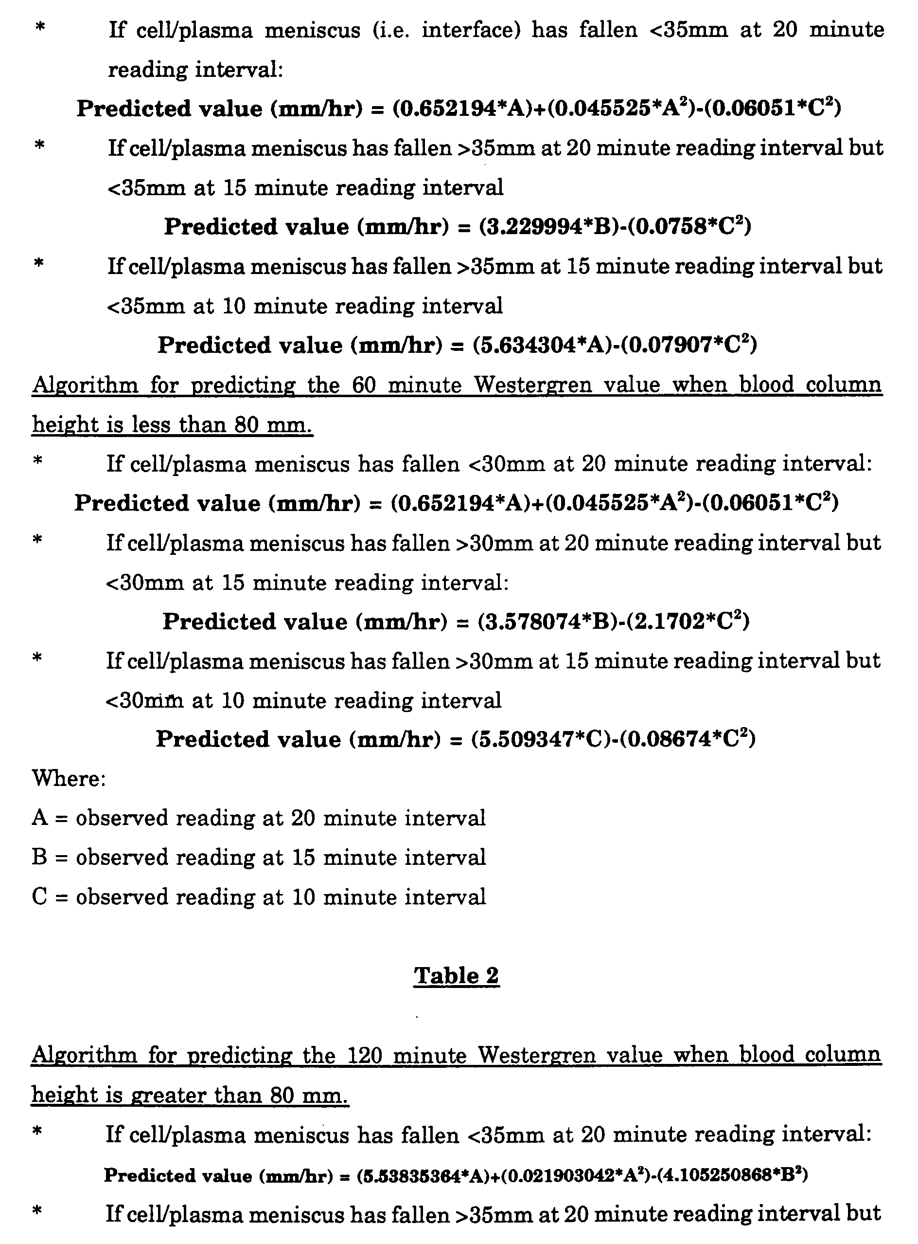
- The method of claim 1, characterized in that said standard Westergren value is computed as a predicted 60 minute Westergren value as follows:Where:a) if the height of said blood column is greater than about 80 mm.If cell/plasma meniscus interface has fallen about <35mm at a first reading interval:
 If cell/plasma interface has fallen > about 35mm at said first reading interval but < about 35mm at a second reading interval
 If cell/plasma interface has fallen > about 35mm at a said second reading interval but < about 35mm at a third reading interval
 b) if the height of said blood column height is less than about 80 mm.If cell/plasma interface has fallen < about 30mm at said first reading interval:
 If cell/plasma interface has fallen > about 30mm at said first reading interval but < about 30mm at said second reading interval:
 If cell/plasma interface has fallen > about 30mm at said second reading interval but < about 30mm at said third reading interval
 A = observed reading at said first intervalB = observed reading at said second intervalC = observed reading at said third intervala1-a11 are constant values.
 - The method of claim 16, characterized in that said constant values (a1-a11) are as follows:a1 = 0.652194a2 = 0.045525a3 = 0.06051a4 = 3.229994a5 = 0.0758a6 = 5.634304a7 = 0.07907a8 = 3.578074a9 = 2.1702a10 = 5.509347a11 = 0.08674
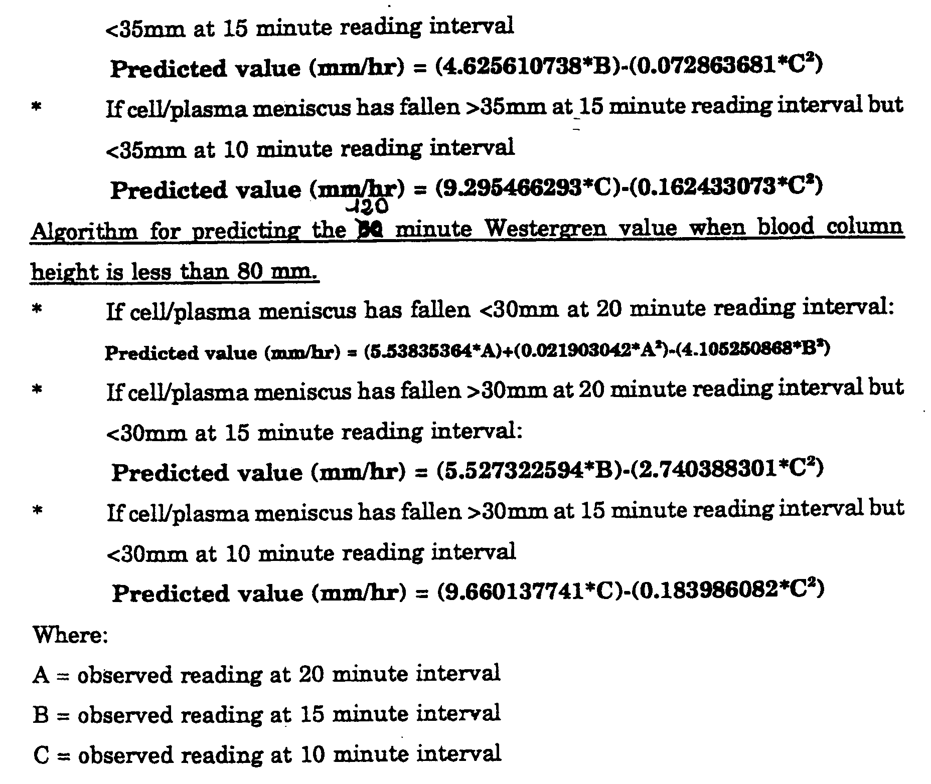
- The method of claim 1, characterized in that said standard Westergren value is computed as a predicted 120 minute Westergren value as follows:Where:a) if the height of said blood column height is greater than about 80 mmIf cell/plasma interface has fallen < about 35mm at a first reading interval:
 If cell/plasma interface has fallen > about 35mm at said first reading interval but < about 35mm at a second reading interval
 if cell/plasma interface has fallen > about 35mm at said second reading interval but < about 35mm at a third reading interval
 b) if the height of said blood column is less than about 80 mm.If cell/plasma interface has fallen < about 30mm at said first reading interval:
 If cell/plasma interface has fallen > about 30mm at said first reading interval but < about 30mm at said second reading interval:
 If cell/plasma interface has fallen > about 30mm at said second reading interval but < about 30mm at said third reading interval
 A = observed reading at said first intervalB = observed reading at said-second intervalC = observed reading at said third intervalb1-b11 are constant values.
 - The method of claim 18, characterized in that said constant values (b1-b11) are as follows:b1 = 5.53835364b2 = 0.021903042b3 = 4.105250868b4 = 4.625610738b5 = 0.072863681b6 = 9.295466293b7 = 0.162433073b8 = 5.527322594b9 = 2.740388301b10 = 9.660137741b11 = 0.183986082
- The method of any claims 16 to 19, characterized in that said first, second and third reading intervals are equal to about 20, 15 and 10 minutes respectively.
- Apparatus for determining the erythrocyte sedimentation rate (ESR) in a blood sample, said apparatus including:test tube means (T) for forming in use a column of said blood, said blood column having a given height at an initial time; anddetector means (3) for measuring at at least one subsequent time interval the location of the cell/plasma interface (I) with respect to the height of said blood column in said test tube means (T), said location being indicative of the ESR of the said blood sample,
characterised in that:said detector means (3) measure the location of said interface over a length (W) being about 50% or less, and typically about 30% or less of the height of said blood column in said test tube means (T) to generate at least one signal indicative of said location, andprocessor means (11) are associated with said detector means (3) said processor means (11) measuring from said at least one signal the location of said cell/plasma interface (I) at at least one first and at least one second intervals of less than 30 minutes, and preferably up to 20 minutes, from said initial time and determine said value representative of the ESR as a standard Westergren value for ESR computed by polynomial interpolation starting from the locations measured at said at least first and said at least second time intervals. - The apparatus of claim 21, characterised in that said detector means (3) measure the location of said interface over a length (W) located at the top of said blood column in said test tube means (T), and in that said test tube means (T) includes a tubular wall adapted for forming a blood column having a length of not less than about 75 mm and not more than about 105 mm said tubular wall having an inside diameter not less than about 5 mm and not more than about 7 mm.
- The apparatus of claim 22, characterised in that said test tube means (T) includes a tubular wall adapted for forming a blood column having a length of about 80 mm and a diameter of about 6 mm.
- The apparatus of any of claims 22 or 23, characterised in that said tubular wall has an outside diameter of not less than about 7 mm and not more than about 9 mm.
- The apparatus of claim 24, characterised in that said tubular wall has an outside diameter of about 8 mm.
- The apparatus of any of claims 21 to 25, characterised in that said length (W) is about 30-40 mm.
- The apparatus of any of claims 21 to 26, characterised in that said test tube means (T) have associated therewith a rotary mounting fixture for mixing the blood forming said column in said test tube means (T) before said initial time.
- The apparatus of claim 27, characterised in that said rotary mounting fixture is arranged for vertical rotation (XR) of said test tube means (T).
- The apparatus of claim 28, characterised in that rotary mounting fixture has associated therewith angular position sensing means (12, 12a) for stopping said rotary mounting fixture at a position (12) where said blood column in said test tube means (T) is inclined with respect to the vertical position.
- The apparatus of any of claims 21 to 29 characterised in that said detector means (3) are optical detecting means (3).
- The apparatus of claim 30, characterised in that it includes a background illumination source (2) for said tube means (T), whereby said optical detecting means (3) detect the location of said cell/plasma interface (1) as a contrasted image against the background illumination of said source (2).
Priority Applications (6)
| Application Number | Priority Date | Filing Date | Title |
|---|---|---|---|
| DE69518834T DE69518834T2 (en) | 1995-07-21 | 1995-07-21 | Method and device for determining the erythrocyte sedimentation rate |
| EP95111491A EP0754945B1 (en) | 1995-07-21 | 1995-07-21 | A method and apparatus for determining the erythrocyte sedimentation rate |
| ES95111491T ES2151939T3 (en) | 1995-07-21 | 1995-07-21 | METHOD AND APPLIANCE TO DETERMINE THE RATE OF SEDIMENTATION OF Erythrocytes. |
| US08/670,475 US5745227A (en) | 1995-07-21 | 1996-06-26 | Method and apparatus for determining the erythrocyte sedimentation rate |
| CA002181634A CA2181634C (en) | 1995-07-21 | 1996-07-19 | A method and apparatus for determining the erythrocyte sedimentation rate |
| JP8192568A JPH09101303A (en) | 1995-07-21 | 1996-07-22 | Erythrocyte-sedimentation-velocity measuring method |
Applications Claiming Priority (1)
| Application Number | Priority Date | Filing Date | Title |
|---|---|---|---|
| EP95111491A EP0754945B1 (en) | 1995-07-21 | 1995-07-21 | A method and apparatus for determining the erythrocyte sedimentation rate |
Publications (2)
| Publication Number | Publication Date |
|---|---|
| EP0754945A1 EP0754945A1 (en) | 1997-01-22 |
| EP0754945B1 true EP0754945B1 (en) | 2000-09-13 |
Family
ID=8219453
Family Applications (1)
| Application Number | Title | Priority Date | Filing Date |
|---|---|---|---|
| EP95111491A Expired - Lifetime EP0754945B1 (en) | 1995-07-21 | 1995-07-21 | A method and apparatus for determining the erythrocyte sedimentation rate |
Country Status (6)
| Country | Link |
|---|---|
| US (1) | US5745227A (en) |
| EP (1) | EP0754945B1 (en) |
| JP (1) | JPH09101303A (en) |
| CA (1) | CA2181634C (en) |
| DE (1) | DE69518834T2 (en) |
| ES (1) | ES2151939T3 (en) |
Cited By (7)
| Publication number | Priority date | Publication date | Assignee | Title |
|---|---|---|---|---|
| US8107715B2 (en) | 2006-05-15 | 2012-01-31 | Sartorius Stedim Biotech Gmbh | Method and detection device for the imaging detection of a sample |
| RU2640190C2 (en) * | 2016-05-04 | 2017-12-26 | Федеральное государственное бюджетное образовательное учреждение высшего образования "Тамбовский государственный технический университет" ФГБОУ ВО ТГТУ | Method for determining change dynamics of erythrocyte sedimentation rate |
| RU2655523C2 (en) * | 2016-10-24 | 2018-05-28 | Федеральное государственное бюджетное образовательное учреждение высшего образования "Тамбовский государственный технический университет" (ФГБОУ ВО "ТГТУ") | Method for determining dynamics of measuring erythrocyte sedimentation rate |
| RU2660710C1 (en) * | 2017-06-27 | 2018-07-09 | Федеральное государственное бюджетное образовательное учреждение высшего образования "Тамбовский государственный технический университет" (ФГБОУ ВО "ТГТУ") | Method for determining the dynamics of the change in the rate of erythrocyte sedimentation |
| RU2695072C1 (en) * | 2018-03-06 | 2019-07-19 | Федеральное государственное бюджетное образовательное учреждение высшего образования "Тамбовский государственный технический университет" (ФГБОУ ВО "ТГТУ") | Method for determining changes in erythrocyte sedimentation rate |
| WO2024002870A1 (en) * | 2022-06-28 | 2024-01-04 | Diesse Diagnostica Senese S.P.A. | Improved system for the measurement of the erythrocyte sedimentation rate and related method |
| WO2024002939A1 (en) * | 2022-06-28 | 2024-01-04 | Diesse Diagnostica Senese S.P.A. | System for the carrying out analyses of blood samples with improved optoelectronic systems |
Families Citing this family (26)
| Publication number | Priority date | Publication date | Assignee | Title |
|---|---|---|---|---|
| US6534016B1 (en) | 1997-04-30 | 2003-03-18 | Richmond Cohen | Additive preparation and method of use thereof |
| US6225123B1 (en) * | 1997-04-30 | 2001-05-01 | Becton Dickinson And Company | Additive preparation and method of use thereof |
| USD432245S (en) * | 1999-07-27 | 2000-10-17 | Becton Dickinson And Company | Collection assembly with a specimen label |
| AU6120799A (en) * | 1999-09-27 | 2001-04-30 | Adelio Missaglia | Apparatus for testing blood samples |
| JP2001245874A (en) * | 2000-03-03 | 2001-09-11 | Sefa Technology Kk | Blood collecting tube for measuring red corpuscle sedimentation speed, blood collecting tube holder, protector for carrying blood collecting tube, and method and device for measuring red corpuscle sedimentation speed |
| US6691057B2 (en) * | 2001-02-26 | 2004-02-10 | L.U.M. Gesellschaft Fur Labor- Umweltdiagnostic & Medizintechnik Mbh | Method and device for accelerated stability analysis |
| DE10218693A1 (en) * | 2002-01-19 | 2003-08-07 | Pvt Probenverteiltechnik Gmbh | Analyzer for blood and body fluids has camera for imaging fluid in vessel for analysis by image-processing software |
| DE10221285A1 (en) * | 2002-01-19 | 2003-08-07 | Pvt Probenverteiltechnik Gmbh | Analyzer for blood and body fluids has camera for imaging fluid in vessel for analysis by image-processing software |
| ES2409268T3 (en) | 2002-01-19 | 2013-06-26 | Roche Pvt Gmbh | Procedure for classifying color images of serum samples from centrifuged body fluids |
| US20030209647A1 (en) * | 2002-05-09 | 2003-11-13 | Lockheed Martin Corporation | Temperature compensating optical debris analysis fixture |
| US20060216829A1 (en) * | 2003-03-21 | 2006-09-28 | Denis Bouboulis | Erythrocyte sedimentation rate (ESR) test measurement instrument of unitary design and method of using the same |
| US6974701B2 (en) * | 2003-03-21 | 2005-12-13 | Hemovations, Llc | Erythrocyte sedimentation rate (ESR) test measurement instrument of unitary design and method of using the same |
| GB0422358D0 (en) * | 2004-10-08 | 2004-11-10 | Rts Thurnall Plc | Determination of the boundaries between fractions and extraction of selected fractions in a fractional sample |
| US20060133963A1 (en) * | 2004-12-16 | 2006-06-22 | Israel Stein | Adapter for attaching information to test tubes |
| US20060157549A1 (en) * | 2005-01-14 | 2006-07-20 | Stein Israel M | Smart cards for automated sample analysis devices |
| US7419832B2 (en) | 2005-03-10 | 2008-09-02 | Streck, Inc. | Blood collection tube with surfactant |
| US7608457B2 (en) * | 2005-03-10 | 2009-10-27 | Streck, Inc. | Blood collection and testing improvements |
| US20060233675A1 (en) * | 2005-04-13 | 2006-10-19 | Stein Israel M | Glass test tube having protective outer shield |
| US20060233676A1 (en) * | 2005-04-13 | 2006-10-19 | Stein Israel M | Glass test tube having protective outer shield |
| DE102007059167A1 (en) * | 2007-12-06 | 2009-06-10 | Synentec Gmbh | Pipette tip for use in e.g. pipetting device in laboratory, has wall comprising transparent region, where transparent region is formed as coplanar measuring windows in optical quality |
| DE102008026803A1 (en) * | 2008-06-03 | 2009-12-10 | Levin, Felix, Dr. | Analysis system for determining substances in liquids, comprises a light-impermeable container, which has light source, sample rack for receiving sample vessels and opening for object lens of digital photo camera, and a fastening device |
| JP2011007697A (en) * | 2009-06-26 | 2011-01-13 | Beckman Coulter Inc | Autoanalyzer |
| US20110226045A1 (en) * | 2009-11-25 | 2011-09-22 | Mcquillan Adrian Charles | Liquid analysis system |
| US20180339291A1 (en) * | 2015-09-10 | 2018-11-29 | Jose Felix Manfredi | Digital Titrator |
| FR3040891B1 (en) * | 2015-09-14 | 2019-05-31 | Olivier Charansonney | DEVICE FOR DISAGGREGATING A COMPLEX MEDIUM |
| CN109998561B (en) * | 2019-05-15 | 2022-01-28 | 广西中医药大学附属瑞康医院 | Disposable blood coagulation vacuum blood collection tube |
Family Cites Families (13)
| Publication number | Priority date | Publication date | Assignee | Title |
|---|---|---|---|---|
| US4045175A (en) * | 1975-12-10 | 1977-08-30 | Ragnar Weber | Micro-method of erythrocyte sedimentation |
| DE2727400A1 (en) * | 1977-06-18 | 1978-12-21 | Strahlen Umweltforsch Gmbh | METHOD OF MEASURING THE SPEED OF MOVEMENT OF A SURFACE OF A PHASE INCLUDED IN A FURTHER PHASE |
| IT1132219B (en) * | 1980-07-22 | 1986-06-25 | Luigi Prandi | COMPOSITION SUITABLE FOR SEPARATING THE EMAZIE FROM THE SERUM OR PLASMA IN BLOOD SAMPLES FOR ANALYSIS AND METHOD THAT USES THEM |
| CA1175673A (en) * | 1981-08-18 | 1984-10-09 | Robert N. O'brien | Erythrocyte settling rate meter |
| NO153508C (en) * | 1984-01-18 | 1986-04-02 | Ken Heimreid | QUICK METHOD FOR DETERMINING THE REDUCTION IN VENE BLOOD. |
| FR2566126B1 (en) * | 1984-06-13 | 1988-05-06 | Cinqualbre Paul | METHOD AND APPARATUS FOR AUTOMATICALLY DETERMINING, DISPLAYING AND PRINTING THE SEDIMENTATION SPEED OF SUSPENDED PARTICLES IN A BIOLOGICAL LIQUID |
| DE3529455A1 (en) * | 1984-08-24 | 1986-03-06 | Becton Dickinson GmbH, 6900 Heidelberg | Test tube for medical laboratories |
| US4801428A (en) * | 1986-10-27 | 1989-01-31 | Becton, Dickinson And Company | Blood sample sedimentation test kit |
| US4848900A (en) * | 1987-06-22 | 1989-07-18 | Kuo Cheng Deng | Computerized automatic monitoring and recording system of erythrocyte sedimentation process |
| US5003488A (en) * | 1989-03-10 | 1991-03-26 | Gespac, Inc. | Automatic fluid sedimentation rate measurement apparatus and method |
| IT217679Z2 (en) * | 1989-09-26 | 1992-01-16 | Diesse Diagnostica | DEVICE FOR DETERMINING THE SPEED OF ERYTHROSEDIMENTATION (VES) AND OTHER |
| JP2540649B2 (en) * | 1990-04-27 | 1996-10-09 | テルモ株式会社 | Blood collection tube |
| US5594164A (en) * | 1994-07-12 | 1997-01-14 | Bull; Brian S. | Method and apparatus for rapid determination of blood sedimentation rate |
-
1995
- 1995-07-21 ES ES95111491T patent/ES2151939T3/en not_active Expired - Lifetime
- 1995-07-21 DE DE69518834T patent/DE69518834T2/en not_active Expired - Lifetime
- 1995-07-21 EP EP95111491A patent/EP0754945B1/en not_active Expired - Lifetime
-
1996
- 1996-06-26 US US08/670,475 patent/US5745227A/en not_active Expired - Fee Related
- 1996-07-19 CA CA002181634A patent/CA2181634C/en not_active Expired - Lifetime
- 1996-07-22 JP JP8192568A patent/JPH09101303A/en active Pending
Non-Patent Citations (1)
| Title |
|---|
| "ICSH recommendations for measurement of erythrocyte sedimentation rate", J. CLIN. PATHOL., vol. 46, 1993, pages 198 - 203 * |
Cited By (7)
| Publication number | Priority date | Publication date | Assignee | Title |
|---|---|---|---|---|
| US8107715B2 (en) | 2006-05-15 | 2012-01-31 | Sartorius Stedim Biotech Gmbh | Method and detection device for the imaging detection of a sample |
| RU2640190C2 (en) * | 2016-05-04 | 2017-12-26 | Федеральное государственное бюджетное образовательное учреждение высшего образования "Тамбовский государственный технический университет" ФГБОУ ВО ТГТУ | Method for determining change dynamics of erythrocyte sedimentation rate |
| RU2655523C2 (en) * | 2016-10-24 | 2018-05-28 | Федеральное государственное бюджетное образовательное учреждение высшего образования "Тамбовский государственный технический университет" (ФГБОУ ВО "ТГТУ") | Method for determining dynamics of measuring erythrocyte sedimentation rate |
| RU2660710C1 (en) * | 2017-06-27 | 2018-07-09 | Федеральное государственное бюджетное образовательное учреждение высшего образования "Тамбовский государственный технический университет" (ФГБОУ ВО "ТГТУ") | Method for determining the dynamics of the change in the rate of erythrocyte sedimentation |
| RU2695072C1 (en) * | 2018-03-06 | 2019-07-19 | Федеральное государственное бюджетное образовательное учреждение высшего образования "Тамбовский государственный технический университет" (ФГБОУ ВО "ТГТУ") | Method for determining changes in erythrocyte sedimentation rate |
| WO2024002870A1 (en) * | 2022-06-28 | 2024-01-04 | Diesse Diagnostica Senese S.P.A. | Improved system for the measurement of the erythrocyte sedimentation rate and related method |
| WO2024002939A1 (en) * | 2022-06-28 | 2024-01-04 | Diesse Diagnostica Senese S.P.A. | System for the carrying out analyses of blood samples with improved optoelectronic systems |
Also Published As
| Publication number | Publication date |
|---|---|
| CA2181634A1 (en) | 1997-01-22 |
| ES2151939T3 (en) | 2001-01-16 |
| EP0754945A1 (en) | 1997-01-22 |
| DE69518834D1 (en) | 2000-10-19 |
| US5745227A (en) | 1998-04-28 |
| CA2181634C (en) | 2002-12-17 |
| DE69518834T2 (en) | 2001-01-11 |
| JPH09101303A (en) | 1997-04-15 |
Similar Documents
| Publication | Publication Date | Title |
|---|---|---|
| EP0754945B1 (en) | A method and apparatus for determining the erythrocyte sedimentation rate | |
| US5914272A (en) | Test method for determining the erythrocyte sedimentation rate and a surfactant for use therein | |
| EP0755654B1 (en) | A test tube for determining the erythrocyte sedimentation rate and a surfactant for use therein | |
| US6506606B1 (en) | Method and apparatus for determining erythrocyte sedimentation rate and hematocrit | |
| US5827746A (en) | Method to determine the sedimentation of blood and relative device | |
| US4927545A (en) | Method and apparatus for automatic processing and analyzing of blood serum | |
| US6797518B1 (en) | Analysis method with sample quality measurement | |
| CA1198970A (en) | Apparatus to evaluate the "erythrayte sedimentation rate" (esr) in several samples | |
| US6336358B1 (en) | Method and apparatus for measuring sedimentation rate of sediments in liquid sample | |
| US20070048185A1 (en) | Hematological analyzer on whole blood with stirring device | |
| US6706536B1 (en) | Method and apparatus for processing coagulation studies, chemistry procedures and the like | |
| EP1062493A1 (en) | Method of measuring erythrocyte sedimentation rate (esr) or plasma fibrinogen of a blood sample | |
| KR20190067777A (en) | How to measure the glycated hemoglobin ratio | |
| JP5575410B2 (en) | Automatic analyzer | |
| CN109923420A (en) | For measuring the separable box of glycosylated hemoglobin | |
| JPH049734A (en) | Apparatus for dispensing liquid sample | |
| JP2003240777A (en) | Blood inspection system | |
| JP2004117219A (en) | Sedimentation speed measurement method and its system of liquid sample | |
| JPS62226059A (en) | Automatic chemical analyzer | |
| JPH09236600A (en) | Method and device for measuring feces occult blood | |
| JPH05307042A (en) | Automatic blood analyzing device | |
| JPS6027859A (en) | Automatic erythrocyte sedimentation rate meter | |
| IT8209489A1 (en) | APPARATUS FOR THE DETERMINATION OF THE SPEED OF ERYTHROSEDIMENTATION OF THE BLOOD (ESR) ON A PLURALITY OF SAMPLES |
Legal Events
| Date | Code | Title | Description |
|---|---|---|---|
| PUAI | Public reference made under article 153(3) epc to a published international application that has entered the european phase |
Free format text: ORIGINAL CODE: 0009012 |
|
| 17P | Request for examination filed |
Effective date: 19960730 |
|
| AK | Designated contracting states |
Kind code of ref document: A1 Designated state(s): DE ES FR GB IT |
|
| AX | Request for extension of the european patent |
Free format text: LT;LV;SI |
|
| 17Q | First examination report despatched |
Effective date: 19990324 |
|
| GRAG | Despatch of communication of intention to grant |
Free format text: ORIGINAL CODE: EPIDOS AGRA |
|
| GRAG | Despatch of communication of intention to grant |
Free format text: ORIGINAL CODE: EPIDOS AGRA |
|
| GRAG | Despatch of communication of intention to grant |
Free format text: ORIGINAL CODE: EPIDOS AGRA |
|
| GRAH | Despatch of communication of intention to grant a patent |
Free format text: ORIGINAL CODE: EPIDOS IGRA |
|
| GRAH | Despatch of communication of intention to grant a patent |
Free format text: ORIGINAL CODE: EPIDOS IGRA |
|
| GRAA | (expected) grant |
Free format text: ORIGINAL CODE: 0009210 |
|
| AK | Designated contracting states |
Kind code of ref document: B1 Designated state(s): DE ES FR GB IT |
|
| ITF | It: translation for a ep patent filed |
Owner name: JACOBACCI & PERANI S.P.A. |
|
| REF | Corresponds to: |
Ref document number: 69518834 Country of ref document: DE Date of ref document: 20001019 |
|
| ET | Fr: translation filed | ||
| REG | Reference to a national code |
Ref country code: ES Ref legal event code: FG2A Ref document number: 2151939 Country of ref document: ES Kind code of ref document: T3 |
|
| PLBE | No opposition filed within time limit |
Free format text: ORIGINAL CODE: 0009261 |
|
| STAA | Information on the status of an ep patent application or granted ep patent |
Free format text: STATUS: NO OPPOSITION FILED WITHIN TIME LIMIT |
|
| 26N | No opposition filed | ||
| REG | Reference to a national code |
Ref country code: GB Ref legal event code: IF02 |
|
| PGFP | Annual fee paid to national office [announced via postgrant information from national office to epo] |
Ref country code: ES Payment date: 20050727 Year of fee payment: 11 |
|
| PGFP | Annual fee paid to national office [announced via postgrant information from national office to epo] |
Ref country code: IT Payment date: 20060731 Year of fee payment: 12 |
|
| REG | Reference to a national code |
Ref country code: ES Ref legal event code: FD2A Effective date: 20060722 |
|
| PG25 | Lapsed in a contracting state [announced via postgrant information from national office to epo] |
Ref country code: ES Free format text: LAPSE BECAUSE OF NON-PAYMENT OF DUE FEES Effective date: 20060722 |
|
| PG25 | Lapsed in a contracting state [announced via postgrant information from national office to epo] |
Ref country code: IT Free format text: LAPSE BECAUSE OF NON-PAYMENT OF DUE FEES Effective date: 20070721 |
|
| PGFP | Annual fee paid to national office [announced via postgrant information from national office to epo] |
Ref country code: DE Payment date: 20140729 Year of fee payment: 20 |
|
| PGFP | Annual fee paid to national office [announced via postgrant information from national office to epo] |
Ref country code: FR Payment date: 20140717 Year of fee payment: 20 Ref country code: GB Payment date: 20140729 Year of fee payment: 20 |
|
| REG | Reference to a national code |
Ref country code: DE Ref legal event code: R071 Ref document number: 69518834 Country of ref document: DE |
|
| REG | Reference to a national code |
Ref country code: GB Ref legal event code: PE20 Expiry date: 20150720 |
|
| PG25 | Lapsed in a contracting state [announced via postgrant information from national office to epo] |
Ref country code: GB Free format text: LAPSE BECAUSE OF EXPIRATION OF PROTECTION Effective date: 20150720 |