EP0760272A1 - A multi-degree-of-freedom positioning mechanism - Google Patents
A multi-degree-of-freedom positioning mechanism Download PDFInfo
- Publication number
- EP0760272A1 EP0760272A1 EP96305562A EP96305562A EP0760272A1 EP 0760272 A1 EP0760272 A1 EP 0760272A1 EP 96305562 A EP96305562 A EP 96305562A EP 96305562 A EP96305562 A EP 96305562A EP 0760272 A1 EP0760272 A1 EP 0760272A1
- Authority
- EP
- European Patent Office
- Prior art keywords
- links
- degree
- moving members
- couplings
- arbor
- Prior art date
- Legal status (The legal status is an assumption and is not a legal conclusion. Google has not performed a legal analysis and makes no representation as to the accuracy of the status listed.)
- Granted
Links
Images


Classifications
-
- B—PERFORMING OPERATIONS; TRANSPORTING
- B25—HAND TOOLS; PORTABLE POWER-DRIVEN TOOLS; MANIPULATORS
- B25J—MANIPULATORS; CHAMBERS PROVIDED WITH MANIPULATION DEVICES
- B25J9/00—Programme-controlled manipulators
- B25J9/10—Programme-controlled manipulators characterised by positioning means for manipulator elements
- B25J9/106—Programme-controlled manipulators characterised by positioning means for manipulator elements with articulated links
-
- A—HUMAN NECESSITIES
- A47—FURNITURE; DOMESTIC ARTICLES OR APPLIANCES; COFFEE MILLS; SPICE MILLS; SUCTION CLEANERS IN GENERAL
- A47B—TABLES; DESKS; OFFICE FURNITURE; CABINETS; DRAWERS; GENERAL DETAILS OF FURNITURE
- A47B2200/00—General construction of tables or desks
- A47B2200/0035—Tables or desks with features relating to adjustability or folding
- A47B2200/005—Leg adjustment
- A47B2200/0056—Leg adjustment with a motor, e.g. an electric motor
Abstract
Description
- The present invention relates to a multi-degree-of-freedom positioning mechanism which can be applied to precision measuring instruments, precision machine tools, precision assembling apparatuses, etc.
- In the past, machine tools and manipulators of robots had been designed on a ready-made idea that a cantilever structure was the best.
- However, in recent years, a structure to destroy the ready-made idea begins to be marketed as products. The structure is called a parallel mechanism, and has a plurality of links connected in parallel between an end effector (called a table in this specification) and a base. These links are either of telescopic type or of folding type.
- This structure is generally said to provide high precision, high rigidity and high speed, compared to the previous cantilever structure (see Nikkei Mechanical).
- However, on the other hand, the calculation of table position and attitude control is complicated, to make the software complicated and expensive. In addition, telescopic type links are narrow in traveling range, and folding type links have problems in view of precision and dynamics.
- The present invention is proposed to overcome these disadvantages. The object of the present invention is to provide a multi-degree-of-freedom positioning mechanism simplified in mechanism, larger in traveling range and easy in attitude control.
- To solve the above problem, the multi-degree-of-freedom positioning mechanism of the present invention can comprise at least a guide shaft and first and second moving members movably mounted on the guide shaft; one each drive, being connected with the first and second moving members, to allow the first and second moving members to travel on the guide shaft individually; the ends of a pair of foldably joined equally long links, being pivotally rotatably engaged with the first and second moving members, through first and second couplings; and one edge of a table, being pivotally rotatably engaged with the joint between the mating links of the pair, to displaceably support the table.
- Furthermore, the multi-degree-of-freedom positioning mechanism of the present invention can comprise first and second guide shafts and first and second moving members movably mounted on each of the first and second guide shafts; one each drive, being connected with the respective first and second moving members, to allow the respective first and second moving members to travel on the first and second guide shafts individually; the ends of two pairs of foldably joined equally long links, being pivotally rotatably engaged with the respective first and second moving members, through respective first and second couplings; and two opposite edges of a table, being pivotally rotatably engaged with the two joints between the mating links of the respective pairs, to displaceably support the table.
- In the above configuration of the present invention, each of the second couplings can be provided with a rotation arrester in which an arbor is rotatably mounted in a bracket provided on the second moving member, with both the ends of the arbor protruding from the bracket, and has its one end rotatably engaged with the end of the link, to prevent the rotation of the arbor around itself.
- Still furthermore, the multi-degree-of-freedom positioning mechanism of the present invention can comprise first and second guide shafts and first and second moving members movably mounted on each of the first and second guide shafts; one each drive, being connected with the respective first and second moving members, to allow the respective first and second moving members to travel on the first and second guide shafts individually; the ends, on one side, of two pairs of equally long links mutually pivotally rotatably connected in cross at their intermediate points, being engaged with the respective first and second moving members, through respective first and second couplings; the ends, on the other side, of said two pairs of links, being pivotally rotatably engaged with the ends of a respectively corresponding pair of foldably joined equally long links; and two opposite edges of a table, being pivotally rotatably engaged with the two joints between the mating links of the respective pairs, to displaceably support the table.
- In the above configuration of the present invention, each of the second couplings can be provided with a rotation arrester in which an arbor is rotatably mounted in a bracket provided on the second moving member, with both the ends of the arbor protruding from the bracket, and has its one end rotatably engaged with the end of the link, to prevent the rotation of the arbor around itself.
- Still furthermore, the multi-degree-of-freedom positioning mechanism of the present invention can comprise first, second and third guide shafts and first and second moving members movably mounted on each of the first, second and third guide shafts; one each dive, being connected with the respective first and second moving members, to allow the respective first and second moving members to travel on the first, second and third guide shafts individually; the ends of three pairs of foldably joined equally long links, being pivotally rotatably engaged with the respective first and second moving members, through respective first and second couplings; and three edges of a table, being pivotally rotatably engaged with the three joints between the mating links of the respective pairs, to displaceably support the table.
- In the above configuration of the present invention, each of the second couplings can be provided with a rotation arrester in which an arbor is rotatably mounted in a bracket provided on the second moving member, with both the ends of the arbor protruding from the bracket, and has its one end rotatably engaged with the end of the link, to prevent the rotation of the arbor around itself.
- Still furthermore, the multi-degree-of-freedom positioning mechanism of the present invention can comprise first, second and third guide shafts and first and second moving members movably mounted on each of the first, second and third guide shafts; one each drive, being connected with the respective first and second moving members, to allow the respective first and second moving members to travel on the first, second and third guide shafts individually; the ends, on one side, of three pairs of equally long links mutually pivotally rotatably connected in cross at their intermediate points, being engaged with the respective first and second moving members, through respective first and second couplings; the ends, on the other side, of said three pairs of links, being pivotally rotatably engaged with the ends of a respectively corresponding pair of foldably joined equally long links; and three edges of a table, being pivotally rotatably engaged with the three joints between the mating links of the respective pairs, to displaceably support the table.
- In the above configuration of the present invention, each of the second couplings can be provided with a rotation arrester in which an arbor is rotatably mounted in a bracket provided on the second moving member, with both the ends of the arbor protruding from the bracket, and has its one end rotatably engaged with the end of the link, to prevent the rotation of the arbor around itself.
- Since the positions of the two joints between the mating links of the two pairs can be easily detected from the positions of the respective first and second moving members on the first and second guide shafts, table position and attitude control can be easily calculated.
- Furthermore, when a pair of links and the table are located to form a straight line (dead point), stopping the pivotal rotation of the pair of links around its guide shaft and operating another pair of links allow the table to progress from the dead point in a desired direction. Therefore, the traveling range of the table increases by that.
- Moreover, if the table is pivotally rotatably supported by three pairs of links engaged with the respective moving members on the first, second and third guide shafts, further more delicate table attitude control can be carried out.
- If pairs of equally long links mutually pivotally rotatably connected in cross at their intermediate points and pairs of foldably joined equally long links are used to support the table, the displaceable range of the table can be further expanded.
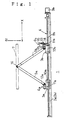
- [Fig. 1] A typical side illustration showing the multi-degree-of-freedom positioning mechanism of the present invention as an example.
- [Fig. 2] A plan illustration of the multi-degree-of-freedorm positioning mechanism shown in Fig. 1.
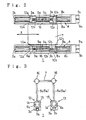
- [Fig. 3] A typical side illustration showing the function of the couplings of the multi-degree-of-freedom positioning mechanism shown in Fig. 1.
- [Fig. 4] Symbolic illustrations showing the degrees of freedom of the couplings applied in the multi-degree-of-freedom positioning mechanism of the present invention.
- [Fig. 5] Symbolic illustrations showing the action states of the rotation arrester applied in the multi-degree-of-freedom positioning mechanism of the present invention.
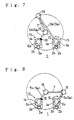
- [Fig- 6] A typical side illustration showing an action of the multi-degree-of-freedom positioning mechanism shown in Fig. 1.
- [Fig. 7] A typical side illustration showing an action of the mutti-degree-of-freedom positioning mechanism shown in Fig. 1.
- [Fig. 8] A typical side illustration showing an action of the multi-degree-of-freedom positioning mechanism shown in Fig. 1.
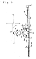
- [Fig. 9] A typical side illustration showing the multi-degree-of-freedom positioning mechanism of the present invention as another example.
- [Fig. 10] A typical side illustration for explaining the function of the multi-degree-of-freedom positioning mechanism shown in Fig. 9.
- [Fig. 11] A typical plan illustration of the multi-degree-of-freedom positioning mechanism shown in Fig. 10.
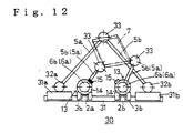
- [Fig. 12] A typical side illustration for explaining the actions of the multi-degree-of-freedom positioning mechanism shown in Fig. 10.
- [Fig. 13] A typical side illustration showing the multi-degree-of-freedom positioning mechanism of the present invention as a further other example.
- [Fig. 14] A typical side illustration of the multi-degree-of-freedom positioning mechanism shown in Fig. 13.
- [Fig. 15] Another typical side illustration of the multi-degree-of-freedom positioning mechanism shown in Fig. 13.
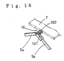
- [Fig. 16] A perspective view for mainly illustrating the coupling of two in the degree
- [Fig. 17] A side view showing an example of the pivotal rotation preventing means in the mechanism of the first type
- [Fig. 18] A side view showing an example of the pivotal rotation preventing means in the mechanism of the second type
- [Fig. 19] A sectional view showing an example of the coupling of three in the degree of freedom
- [Fig. 20] A sectional view showing an example of the coupling of three in the degree of freedom, after some motion from the state of Fig. 18.
- The multi-degree-of-freedom positioning mechanism of the present invention is described below based on the attached drawings.
- Figs. 1, 2 and 6 show the basic configuration of an example embodying the first type of the multi-degree-of-
freedom positioning mechanism 1 of the present invention. The multi-degree-of-freedom positioning mechanism 1 is composed of first andsecond guide shafts members second guide shafts members drives 4 are selectively controlled to allow the respective first and second slidingmembers second guide shafts - The respective first and second sliding
members second guide shafts long links second couplings first guide shaft 2a and in the direction to cross thefirst guide shaft 2a. - At the joints between the
mating links - The
drives 4 on each of theguide shafts shafts second guide shafts motors shafts shafts members members shafts shafts motors members members - So, if the
motor 9a is selected and actuated for example, to rotate the threadedshaft 8a only, the internally threaded member 10 threadedly engaged with it is moved along the threadedshaft 8a, to slide the first slidingmember 3a only along thefirst guide shaft 2a (or thefirst guide shaft 2b). - On the other hand, if the
motor 9b is selected and actuated to rotate the threadedshaft 8b, the internally threadedmember 10b threadedly engaged with it is moved along the threadedshaft 8b, to slide the second slidingmember 3b along thefirst guide shaft 2a (or thesecond guide shaft 2b). - Furthermore, if both the
motors shafts members shafts members first guide shaft 2a (or thesecond guide shaft 2b). - As described above, in the
drives 4, if the threadedshafts 8a and/or 8b to be rotated by themotors 9a and/or 9b is selected, either the first or second slidingmember first guide shaft 2a (or thesecond guide shaft 2b), or both the first and second slidingmembers first guide shaft 2a (or thesecond guide shaft 2b). When both the first and second slidingmembers first guide shaft 2a (or thesecond guide shaft 2b), the first and second slidingmembers - Moreover, the threaded progression directions on the threaded
shafts shaft members shafts motors - In the first and
second couplings arbors brackets members grooved heads 12h of thearbors links grooved heads 12h of thearbors respective links second couplings links members - Furthermore, each of the
second couplings 6b is provided with arotation arrester 13 to prevent the rotation of thearbor 12b around itself. Therotation arrester 13 consists of adisc 14 installed at the end on the side opposite to thegrooved head 12h, of thearbor 12b protruded from thebracket 11b, and aclamp 15 for grasping thedisc 14 on both sides of thedisc 14, to prevent the rotation of thedisc 14, thereby preventing the rotation of thearbor 12b. - Each of the
third couplers 16 connecting the joints between the respectivelymating links first guide shaft 2a (or thesecond guide shaft 2b) and in the direction to cross thefirst guide shaft 2a (or thesecond guide shaft 2b). Fig. 16 shows an example of thethird coupling 16 on thefirst guide shaft 2a, which consists of agrooved member 100 on the table 7 side and alink coupling member 101 pivotally rotatably fitted in the groove of thegrooved member 100, and thelink coupling member 101 is protruded transversely from the joint between thelinks mating links third coupling 16 can rotate around two axes orthogonal to each other, it assures two in the degree of freedom while it connects the joint between thelinks - Fig. 3 typically shows the first type of the multi-degree-of-
freedom mechanism 1. As described above, since the first, second andthird couplings - As shown in Fig. 3, the
second couplings 6b at the second slidingmembers 3b on the first andsecond guide shafts rotation arresters 13. So, the symbols as illustrated are used. In each of therotation arresters 13, theclamp 15 is actuated to grasp thedisc 14, for preventing the rotation of thearbor 12b around itself, and the rotation-arrested state is expressed by smearing out the symbol of theclamp 15 as shown in Fig. 5. On the other hand, when therotation arrester 13 is not actuated, thearbor 12 b is in a rotatable state which is expressed by keeping the symbol of theclamp 15 open. - In the above configuration, if the
motors drives 4 are started and controlled selectively, considering the respective rotation angles and directions, to rotate either or both of the respective threadedshafts members 3a and/or 3b are slid, as intended, together with the respective internally threadedmembers 10a and/or 10b on the first and/orsecond guide shafts 2a and/or 2b, to change the respective relative positional relations between the first and second slidingmembers second guide shafts 2a and/or 2b. - Such actions of the first and second sliding
members respective links second couplings second guide shafts second guide shafts links third couplings 16 at the joints between the respectivelymating links second guide shafts second guide shafts - The action example of the first type of the multi-degree-of-freedom positioning mechanism described above is described below in more detail.
- At first, the
drives 4 are controlled to slide the respective first and second slidingmembers members second guide shafts - This control can be effected by controlling the two pairs of the
motors second guide shafts shafts shafts respective motors shafts - If the respective first and second sliding
members second guide shafts members third couplings 16 located at the joints between the respectivelymating links second guide shafts third couplings 16 are kept constant. Therefore, the table 7 is displaced in the axial direction (X direction in Fig. 1) of the first andsecond guide shafts - In another case, the
drives 4 are controlled to slide the respective first and second slidingmembers second guide shafts second guide shafts second members - In this case, the
third couplings 16 located at the joints between the respectivelymating links second guide shafts - That is, if the respective first and second sliding
members mating links members mating links - Therefore, this control action causes the table 7 to be raised or lowered vertically (Y direction in Fig. 1), i.e., adjusted in height, while its supported state is kept constant.
- In a further other case, in the state of Fig. 3, the
rotation arrester 13 of thesecond coupling 6b at the second slidingmember 3b on thesecond guide shaft 2b is actuated to let theclamp 15 grasp thedisc 14 for preventing the rotation of thearbor 12 around itself, and in this state, thedrives 4 are started to slide the first and second slidingmembers first guide shaft 2b only, in such a way that the first and second slidingmembers third coupling 16 connected with thelinks first guide shaft 2a descends, while thethird coupling 16 connected with thelinks second guide shaft 2b keeps its height. As described above, since thearbor 12b supporting themating links second guide shaft 2b is prevented from being rotated around itself, thethird coupling 16 at the joint between thesemating links second guide shaft 2b. - Therefore, the table 7 is pivotally rotated to gradually descend with the
third coupling 16 at the joint between themating links second guide shaft 2b as a pivot, as thethird coupling 16 connected with thelinks first guide shaft 2a descends. That is, since thearbor 12b supporting thelinks first guide shaft 2a is not prevented from being rotated around itself, thelinks first guide shaft 2a are pivotally rotated around the axis of thearbor 12b installed along thefirst guide shaft 2a, i.e., rotated in the direction to cross thefirst guide shaft 2a. In this action, the table 7 can be lowered and inclined to an angle equal to the inclination angle of thelinks - In the state of Fig. 6, if the
drives 4 are started to slide the first and second slidingmembers first guide shaft 2a only at the same speed, in such a way that the first and second slidingmembers third coupling 16 connected with thelinks first guide shaft 2a ascends. So, the table 7 is displaced in reverse to the above mentioned action, to return to the state of Fig. 3. - If the same action is continued further still after the table 7 has returned to the state of Fig. 3, the table 7 is rotated to gradually ascend, with the
third coupling 16 at the joint between themating links second guide shaft 2b as a pivot, as thethird coupling 16 connected with thelinks first guide shaft 2a ascends. - In the above action, the
arbor 12b for the second slidingmember 3b on thesecond guide shaft 2b is prevented from being rotated around itself. It is evident that even if only therotation arrester 13 of thesecond coupling 6b at the second slidingmember 3b on thefirst guide shaft 2a is actuated to let theclamp 15 grasp thedisc 14 for preventing the rotation of thearbor 12b around itself, the same actions as described above can occur. In this case, thethird coupling 16 connected with thelinks first guide shaft 2a acts as the pivot of the table 7. - In the first type of the multi-degree-of-freedom positioning mechanism, the following action can be effected in addition to the basic actions described above.
- In the state of Fig. 6, the
rotation arrester 13 of thesecond coupling 6b at the second slidingmember 3b on thefirst guide shaft 2a is actuated to let theclamp 15 grasp thedisc 14, for arresting the rotation of thearbor 12b around itself, while therotation arrester 13 of thesecond coupling 6b at the second slidingmember 3b on thesecond guide shaft 2b side is released from its actuated state, to allow thearbor 12b to be rotated around itself. - In this state, if the
drives 4 are started to slide the first and second slidingmembers second guide shaft 2b at the same speed in an action similar to the above, in such a way that the first and second slidingmembers third coupling 16 connected with thelinks second guide shaft 2b ascends. So, the table 7 is pivotally rotated to ascend and to be steep in inclination, with thethird coupling 16 at the joint between themating links first guide shaft 2a as a pivot. Finally, the table 7 exceeds an inclination angle of 90 degrees, to the extreme end of a proper stroke where the parts threaten to interfere with each other, as shown in Fig. 7. - On the other hand, in the state of 6, the
rotation arrester 13 of thesecond coupling 6b at the second slidingmember 3b on thefirst guide shaft 2a is actuated to let theclamp 15 grasp thedisc 14, for arresting the rotation of thearbor 12b around itself, and therotation arrester 13 of thesecond coupling 6b at the second slidingmember 3b on thesecond guide shaft 2b side is released from its actuated state, to allow thearbor 12b to be rotated around itself. In this state, if thedrives 4 are started to slide the first and second slidingmembers second guide shaft 2b at the same speed in an action similar to the above, in such a way that the first and second slidingmembers third coupling 16 connected with thelinks second guide shaft 2b descends. So, the table 7 is pivotally rotated to descend and to be gentle in inclination, with thethird coupling 16 at the joint between themating links first guide shaft 2a as a pivot. Thus, the table 7 becomes horizontal again as shown in Fig. 8. However, it is to be noted that even though the table 7 is horizontal, it is lower in height compared with the state of Fig. 3, and is displaced in the direction to cross the first andsecond guide shafts - The above action can be effected even if the second sliding
member 3b with thearbor 12b prevented from being rotated is on thesecond guide shaft 2b side. - Fig. 9 shows the basic configuration of an example embodying the second type of the multi-degree-of-
freedom positioning mechanism 1 of the present invention. The second type has substantially the same components as those of the first type except that only the components corresponding to thelinks - In the multi-degree-of-
freedom positioning mechanism 20 of the second type, the respective first and second slidingmembers second guide shafts long links second couplings links 21a and 22b are engaged with the ends of a respectively corresponding pair of foldably joined equallylong links mating links links mating links links - In the second type, the selectively
controllable drives 4 are provided for the respective first and second slidingmembers rotation arresters 13 are provided for thesecond couplings 6b at the second slidingmembers 3b on the first andsecond guide shafts - The multi-degree-of-
freedom mechanism 20 of the second type can perform all the actions of the first type described above. In addition, the pantograph type links can elongate the strokes in their movement in the direction orthogonal to the direction in which the first and second slidingmembers - As can be seen from the above actions, in the multi-degree-of-freedom positioning mechanisms of the first and second types, the position and attitude of the table 7 can be known in reference to the locations of the respective first and second sliding
members second guide shafts drives 4 are actuated while detecting the locations of the respective first and second slidingmembers - It is to be noted here that the description of the multi-degree-of-
freedom mechanisms third couplings 16, i.e., as described above, around the axis in the direction to cross the first andsecond guide shafts freedom mechanisms third couplings 16 on each of both the linearly arranged sides, and no means for preventing the pivotal rotation of the table 7 caused by any load on the table 7 is illustrated. - An example of the pivotal rotation preventing means is described below. Fig. 17 shows an example of the pivotal rotation preventing means for the multi-degree-of-
freedom positioning mechanism 1 of the first type. In this means, anarbor 12a' is additionally installed on the first slidingmember 3a, and a third coupling 16' is also additionally installed for the table 7. And between the additionally installedarbor 12a' and third coupling 16', anotherlink 5a' is connected along thelink 5a to form a parallel link mechanism. It is evident that this configuration can prevent the pivotal rotation of the table 7 around the axis of thethird coupling 16, i.e., around the axis perpendicular to the paper surface. - Fig. 18 shows an example of the pivotal rotation preventing means for the multi-degree-of-
freedom positioning mechanism 20 of the second type. In this means, as in the means for the first type described above, anarbor 12a' is additionally installed on the first slidingmember 3a, and a third coupling 16' is additionally installed for the table 7. Andlinks 5b' and 21a' respectively parallel to thelinks arbor 12a' and the third coupling 16', and holdinglinks links links 5b' and 21a', and between the crossed point of thelinks link 21a'. It is also evident that this configuration can prevent the pivotal rotation of the table 7 around the axis of thethird coupling 16, i.e., around the axis perpendicular to the paper surface, by analogy with the pivotal rotation preventing means for the first type described above. - Though not illustrated, even if the support point of the table 7 by either of the
third couplings 16, i.e., the location of the axis as the pivot of the rotation to be prevented on either of the first andsecond guide shafts other guide shaft third couplings 16 are installed to the table 7 can also be used as the pivotal rotation means. - When such a pivotal rotation preventing means is used, not only the
third couplings 16 of two in the degree of freedom but also thethird couplings 16 of three in the degree of freedom described later can be used. - Figs. 10 through 13 show the basic configuration of an example embodying the multi-degree-of-
freedom positioning mechanism 30 of the third type. - The multi-degree-of-
freedom positioning mechanism 30 has the first andsecond guide shafts sixth couplings 33 of three in the degree of freedom are used instead of thethird couplings 16 of two in the degree of freedom, and that thesixth couplings 33 on the first andsecond guide grooves - Figs. 19 and 20 show an example of the
sixth coupling 33 of three in the degree of freedom. - The
sixth coupling 33 consists of afirst member 203 with aspherical body 202 provided at the tip of arod 201, asecond member 205 with a spherical concave 204 larger than the outer diameter of thespherical body 202, and athird member 207 holdingmany balls 206 to fill the clearance formed when thespherical body 202 of thefirst member 203 is fitted in the spherical concave 204 of thesecond member 205. In this configuration, thefirst member 203 and thesecond member 205 can rotate around three axes orthogonal to each other. For example, therod 201 of thefirst member 203 is used as the axis at the joint between themating links second member 205 is fixed to the table 7 (or vice versa), to constitute thecoupling 33 of three in the degree of freedom. - Now back to the description of the entire configuration of the third type, in addition to the above mentioned first and
second guide shafts third guide shaft 31 is provided to be orthogonal to them. On thethird guide shaft 31, fourth and fifth slidingmembers - These fourth and fifth sliding
members third guide shaft 31, like the first and second slidingmembers drives 4 of the first and second types, though the drives for the fourth and fifth slidingmembers - On the fourth and fifth sliding
members long links fifth couplings links second couplings members mating links sixth couplings 33 of three in the degree of freedom, as configured for the first and second slidingmembers sixth coupling 33 on thethird guide shaft 31 is connected with the table 7 is at the edge opposite to the edge, near which thesixth couplings 33 on the first andsecond guide shafts sixth couplings 33 are orthogonal to each other. - According to the third type, since the table 7 can be pivotally rotated around the three axes orthogonal to each other respectively at the points where the table 7 is connected with the
sixth couplings 33, the following actions can be effected in addition to the actions described above for the first and second types. - At first, in a state where the table 7 is supported horizontally as shown in Fig. 10, if the fourth and fifth sliding
members sixth coupling 33 on thethird guide shaft 31, the table 7 is pivotally rotated to descend and incline with the axis across the pair ofsixth couplings 33 on the first andsecond guide shafts sixth coupling 33 on thethird guide shaft 31 is raised, the table 7 is pivotally rotated to ascend and incline with the axis across the pair ofsixth couplings 33 on the first andsecond guide shafts links third guide shaft 31 are pivotally rotated around a virtual axis in parallel to theguide shaft 31. - Contrary to the above, in a state where the table 7 is supported horizontally, even if the respective first and second sliding
members second guide shafts sixth couplings 33 while the fourth and fifth slidingmembers - The mechanism of the third type can perform not only these actions, but also actions caused by combining the actions of the first type and the above mentioned actions effected by the components on the
third guide shaft 3. - For example, if the distance between the first and second sliding
member first guide shaft 2a is elongated while the fourth and fifth slidingmembers third guide shaft 31 are fixed, thesixth coupling 33 between the table 7 and the joint between themating links first guide shaft 2a descends, displacing the table 7 with the position of thesixth coupling 33 as the lowest point. In this case, if therotation arrester 13 of thesecond coupling 6b at the second slidingmember 3b on thefirst guide shaft 2a is actuated to arrest the rotation of thearbor 12b around itself, and the first and second slidingmembers second guide shaft 2b are slid, then thesixth coupling 33 between the table 7 and the joint between themating links second guide shaft 2b also descends, tilting the table 7 in such a way that the edge of the table 7 near thesixth couplings 33 between the table 7 and the joints between therespective mating links second guide shafts - As described above, the table 7 is supported at three points; on both sides at one edge of the table 7 by the
sixth couplings 33 at the joints between therespective mating links members second guide shafts sixth coupling 33 at the joint between themating links members third guide shaft 31. So, the table 7 can be displaced delicately by properly sliding the respective first and second slidingmembers members - Since the locations of the
sixth couplings 33 at which the table 7 is supported can be obtained in reference to the locations of the respective first and second slidingmembers second guide shafts members third guide shaft 31. So, if the drives are actuated while detecting the locations of the respective first and second slidingmembers members - As described above, in the multi-degree-of-
freedom positioning mechanism 30 of the third type, the table 7 can be displaced in the longitudinal (X) direction, transverse (Y) direction, and vertical (Z) direction, and furthermore can be rotated around the Z axis in the drawing. Furthermore, the table 7 in the horizontal state (XY plane) can be tilted in the longitudinal (X) direction and in the transverse (Y) direction. Thus, the table is six in the degree of freedom to allow control in position and attitude. - Figs. 13 through 15 show the basic configuration of an example embodying the fourth type of the multi-degree-of-
freedom positioning mechanism 1 of the present invention. The relation of the fourth type to the third type corresponds to the relation of the second type to the first type, and the fourth type is different from the third type in the components corresponding to thelinks - The multi-degree-of-
freedom positioning mechanism 40 of the fourth type uses so-called pantograph type links as in the second type, instead of the foldably joinedlinks mating links links - Figs 13 through 15 for the
mechanism 40 of the fourth type show drives 4 similar to those described for the first and second types. - The multi-degree-of-
freedom positioning mechanism 40 of the fourth type as described above can perform all the actions of the third type described before. In addition, as described for the mechanism of the second type, the pantograph type links can elongate the strokes in their movement in the direction orthogonal to the direction in which the first and second slidingmembers members - As described above, the table can be displaced in multi-degree of freedom, and the position and attitude of the table can be decided by the locations of the sliding members on the guide shafts. That is, since the present invention allows the position and attitude of the table to be easily derived from the positions of sliding members on guide shafts, the attitude control is easy. Furthermore, the mechanism is simple, and the range of table displacement can be expanded to cater for a wider range of applications.
Claims (9)
- A multi-degree-of-freedom positioning mechanism, comprising at least a guide shaft and first and second moving members movably mounted on the guide shaft, one each drive, being connected with the first and second moving members, to allow the first and second moving members to travel on the guide shaft individually; the ends of a pair of foldably joined equally long links, being pivotally rotatably engaged with the first and second moving members, through first and second couplings; and one edge of a table, being pivotally rotatably engaged with the joint between the mating links of the pair, to displaceably support the table.
- A multi-degree-of-freedom positioning mechanism, comprising first and second guide shafts and first and second moving members movably mounted on each of the first and second guide shafts; one each drive, being connected with the first and second moving members, to allow the respective first and second moving members to travel on the first and second guide shafts individually; the ends of two pairs of foldably joined equally long links, being pivotally rotatably engaged with the respective first and second moving members, through respective first and second couplings; and two opposite edges of a table, being pivotally rotatably engaged with the two joints between the mating links of the respective pairs, to displaceably support the table.
- A multi-degree-of-freedom positioning mechanism, according to Claim 2, wherein each of the second couplings is provided with a rotation arrester in which an arbor is rotatably mounted in a bracket provided on the second moving member, with both the ends of the arbor protruding from the bracket, and has its one end rotatably engaged with the end of the link, to prevent the rotation of the arbor around itself.
- A multi-degree-of-freedom positioning mechanism, comprising first and second guide shafts and first and second moving members movably mounted on each of the first and second guide shafts; one each drive, being connected with the respective first and second moving members, to allow the respective first and second moving members to travel on the first and second guide shafts individually; the ends, on one side, of two pairs of equally long links mutually pivotally rotatably connected in cross at their intermediate points, being engaged with the respective first and second moving members through respective first and second couplings; the ends, on the other side, of said two pairs of links, being pivotally rotatably engaged with the ends of a respectively corresponding pair of foldably joined equally long links; and two opposite edges of a table, being pivotally rotatably engaged with the two joints between the mating links of the respective pairs, to displaceably support the table.
- A multi-degree-of-freedom positioning mechanism, according to Claim 4, wherein each of the second couplings is provided with a rotation arrester in which an arbor is rotatably mounted in a bracket provided on the second moving member, with both the ends of the arbor protruding from the bracket, and has its one end rotatably engaged with the end of the link, to prevent the rotation of the arbor around itself.
- A multi-degree-of-freedom positioning mechanism, comprising first, second and third guide shafts and first and second moving members movably mounted on each of the first, second and third guide shafts; one each drive, being connected with the respective first and second moving members, to allow the respective first and second moving members to travel on the first, second and third guide shafts individually; the ends of three pairs of foldably joined equally long links, being pivotally rotatably engaged with the respective first and second moving members, through respective first and second couplings; and three edges of a table, being pivotally rotatably engaged with the three joints between the mating links of the respective pairs, to displaceably support the table.
- A multi-degree-of-freedom positioning mechanism, according to Claim 6, wherein each of the second couplings is provided with a rotation arrester in which an arbor is rotatably mounted in a bracket provided on the second moving member, with both the ends of the arbor protruding from the bracket, and has its one end rotatably engaged with the end of the link, to prevent the rotation of the arbor around itself.
- A multi-degree-of-freedom positioning mechanism, comprising first, second and third guide shafts and first and second moving members movably mounted on each of the first, second and third guide shafts; one each drive, being connected with the respective first and second moving members, to allow the respective first and second moving members to travel on the first, second and third guide shafts individually; the ends, on one side, of three pairs of equally long links mutually pivotally rotatably connected in cross at their intermediate points, being engaged with the respective first and second moving members through respective first and second couplings; the ends, on the other side, of said three pairs of links, being pivotally rotatably engaged with the ends of a respectively corresponding pair of foldably joined equally long links; and three edges of a table, being pivotally rotatably engaged with the three joints between the mating links of the respective pairs, to displaceably support the table.
- A multi-degree-of-freedom positioning mechanism, according to Claim 8, wherein each of the second couplings is provided with a rotation arrester in which an arbor is rotatably mounted in a bracket provided on the second moving member, with both the ends of the arbor protruding from the bracket, and has its one end rotatably engaged with the end of the link, to prevent the rotation of the arbor around itself.
Applications Claiming Priority (3)
| Application Number | Priority Date | Filing Date | Title |
|---|---|---|---|
| JP19526695 | 1995-07-31 | ||
| JP195266/95 | 1995-07-31 | ||
| JP07195266A JP3117118B2 (en) | 1995-07-31 | 1995-07-31 | Multi-degree-of-freedom positioning mechanism |
Publications (2)
| Publication Number | Publication Date |
|---|---|
| EP0760272A1 true EP0760272A1 (en) | 1997-03-05 |
| EP0760272B1 EP0760272B1 (en) | 1999-09-08 |
Family
ID=16338299
Family Applications (1)
| Application Number | Title | Priority Date | Filing Date |
|---|---|---|---|
| EP96305562A Expired - Lifetime EP0760272B1 (en) | 1995-07-31 | 1996-07-30 | A multi-degree-of-freedom positioning mechanism |
Country Status (4)
| Country | Link |
|---|---|
| US (1) | US5746138A (en) |
| EP (1) | EP0760272B1 (en) |
| JP (1) | JP3117118B2 (en) |
| DE (1) | DE69604140T2 (en) |
Cited By (11)
| Publication number | Priority date | Publication date | Assignee | Title |
|---|---|---|---|---|
| EP0879660A2 (en) * | 1997-05-23 | 1998-11-25 | SCHULER PRESSEN GmbH & Co. | Press with transfer device for workpieces |
| WO1999008832A1 (en) | 1997-08-20 | 1999-02-25 | Mikron Sa Agno | Device for moving and positioning an object in a plane |
| WO2000048442A1 (en) * | 1999-02-12 | 2000-08-17 | Siemens Aktiengesellschaft | Device for providing substrates with electric components by means of several independent robot systems |
| EP1084802A2 (en) * | 1999-09-17 | 2001-03-21 | Toyoda Koki Kabushiki Kaisha | Four-degree-of-freedom parallel robot |
| WO2001047734A1 (en) * | 1999-12-28 | 2001-07-05 | Consejo Superior De Investigaciones Cientificas | Device for a work element having two degrees of mobility |
| EP1137054A1 (en) * | 1999-09-20 | 2001-09-26 | Nikon Corporation | Parallel link mechanism, exposure system and method of manufacturing the same, and method of manufacturing devices |
| WO2002085580A1 (en) * | 2001-04-19 | 2002-10-31 | Consiglio Nazionale Delle Ricerche | Modular and reconfigurable parallel kinematic robot |
| DE10310941A1 (en) * | 2003-03-13 | 2004-10-28 | Fraunhofer-Gesellschaft zur Förderung der angewandten Forschung e.V. | Device for transporting of workpieces through sequence of processing stations has each drive unit for lift and/or opening and closing movement installed outside area of transporting unit and between support rail and machine body |
| DE102009030755A1 (en) * | 2009-06-27 | 2011-01-05 | Fritz Kraft | Handling device for positioning object e.g. ampoule, has shearing levers supported at end-effector support by outer pivot bearings, where translatory degree of freedom of movement is assigned to one of outer bearings |
| CN102886777A (en) * | 2012-10-25 | 2013-01-23 | 浙江理工大学 | Two-degree-of-freedom parallel mechanism with large horizontal displacement |
| CN112207840A (en) * | 2020-09-28 | 2021-01-12 | 镇江瑞昊工程塑料有限公司 | Cantilever type mechanical arm |
Families Citing this family (22)
| Publication number | Priority date | Publication date | Assignee | Title |
|---|---|---|---|---|
| JPH11274031A (en) * | 1998-03-20 | 1999-10-08 | Canon Inc | Aligner, manufacturing device and positioning apparatus |
| DE19813459A1 (en) * | 1998-03-26 | 1999-09-30 | Mettler Toledo Gmbh | Elastic deformable component and method for its production |
| JPH11300557A (en) | 1998-04-15 | 1999-11-02 | Thk Co Ltd | Movable table device |
| JP3072896B1 (en) * | 1999-04-01 | 2000-08-07 | ヒーハイスト精工株式会社 | Hybrid multi-degree-of-freedom mechanism |
| US6295987B1 (en) | 1999-09-16 | 2001-10-02 | Elinor S. Parker | Medical limb rest |
| US8266465B2 (en) | 2000-07-26 | 2012-09-11 | Bridgestone Americas Tire Operation, LLC | System for conserving battery life in a battery operated device |
| US7161476B2 (en) | 2000-07-26 | 2007-01-09 | Bridgestone Firestone North American Tire, Llc | Electronic tire management system |
| US6581486B1 (en) * | 2001-10-11 | 2003-06-24 | Unisys Corporation | Integrated circuit tester having a fail-safe mechanism for moving IC-chips |
| US20090152224A1 (en) * | 2007-12-15 | 2009-06-18 | Ming-Hung Hsieh | Plate Carrying Apparatus |
| US20090174244A1 (en) * | 2008-01-07 | 2009-07-09 | Caterpillar Inc. | Seat height and tilt adjustment apparatus and method |
| JP5771687B2 (en) * | 2010-05-12 | 2015-09-02 | シクマ エアロ シート | Seat table with controlled and optimized route and seat structure with the same |
| US20130014674A1 (en) * | 2011-07-12 | 2013-01-17 | Burkhalter John Charles | Height adjustable desktop apparatus |
| TWI479154B (en) * | 2013-02-04 | 2015-04-01 | King Yuan Electronics Co Ltd | A connecting rods dynamic testing machine and a testing equipment using the same |
| DE102013106388B3 (en) | 2013-06-19 | 2014-10-09 | Limoss Gmbh & Co. Kg | Adjustment mechanism for adjusting movable furniture parts |
| JP6537921B2 (en) * | 2015-08-06 | 2019-07-03 | 三菱重工業株式会社 | Apparatus for producing fiber-reinforced plastic, movable base, method for producing shaped fiber substrate, and method for producing fiber-reinforced plastic |
| US10081990B2 (en) * | 2016-05-13 | 2018-09-25 | Forum Us, Inc. | Kicker system for tubular handling system |
| CN105880979B (en) * | 2016-06-29 | 2017-12-22 | 哈工大机器人集团(哈尔滨)资产经营管理有限公司 | The four sites assembling device of antenna terminal auto-stitching machine |
| US10413055B2 (en) * | 2016-07-08 | 2019-09-17 | Versa Products, Inc. | Motorized, height adjustable desktop system |
| US9961991B1 (en) * | 2016-12-22 | 2018-05-08 | Ying Liang Health Tech. Co., Ltd. | Desktop liftable platform |
| US11491645B2 (en) * | 2019-06-07 | 2022-11-08 | Massachusetts Institute Of Technology | Scissor linkage design and method of operation |
| US20220087414A1 (en) * | 2020-09-23 | 2022-03-24 | Iview Displays (Shenzhen) Company Ltd. | Projection table |
| CN115194817A (en) * | 2022-07-22 | 2022-10-18 | 赵树龙 | Screw rod driving mechanical arm |
Citations (10)
| Publication number | Priority date | Publication date | Assignee | Title |
|---|---|---|---|---|
| US4074600A (en) * | 1975-03-27 | 1978-02-21 | Rouchdy Raphael B | Rotation apparatus for work pieces |
| EP0112099A1 (en) * | 1982-12-16 | 1984-06-27 | Cyber Robotics Limited | Robotic limb |
| EP0127895A2 (en) * | 1983-06-02 | 1984-12-12 | Sumitomo Electric Industries Limited | Positioning mechanism |
| EP0255736A1 (en) * | 1982-09-28 | 1988-02-10 | Tai-Her Yang | Automatic tool exchange apparatus |
| EP0263627A1 (en) * | 1986-09-30 | 1988-04-13 | Dilip Kohli | Robotic manipulators and rotary linear actuators for use in such manipulators |
| US4988244A (en) * | 1989-09-01 | 1991-01-29 | Kearney & Trecker | Six-axis machine tool |
| EP0494565A1 (en) * | 1991-01-11 | 1992-07-15 | Ecole Centrale Des Arts Et Manufactures | Device for moving an object in a translational way in space, especially for a mechanical robot |
| FR2672836A1 (en) * | 1991-02-15 | 1992-08-21 | Onera (Off Nat Aerospatiale) | Articulation device with parallel structure and remote movement-transmission appliances applying it |
| US5378282A (en) * | 1993-06-28 | 1995-01-03 | Pollard; Willard L. | Robotic tool manipulating apparatus |
| GB2295601A (en) * | 1994-11-29 | 1996-06-05 | Toyoda Machine Works Ltd | Machine Tool/Robot Having Parallel Structure |
Family Cites Families (7)
| Publication number | Priority date | Publication date | Assignee | Title |
|---|---|---|---|---|
| US451006A (en) * | 1891-04-21 | Apparatus for marking and cutting cloth | ||
| US2624535A (en) * | 1947-08-20 | 1953-01-06 | Franz W Bollhoefer | Elevating platform for typewriters |
| US3277501A (en) * | 1965-03-22 | 1966-10-11 | George E Frisz | Bed assembly |
| DE2306478A1 (en) * | 1973-02-09 | 1974-08-15 | Grammer Willibald Fa | DEVICE FOR CHANGING THE ALTITUDE AND LONGITUDINAL INCLINATION OF THE SEAT AREA OF SEATS |
| US4744712A (en) * | 1986-05-06 | 1988-05-17 | Ron Mitchell | Apparatus and method for an improved wafer handling system for cantilever type diffusion tubes |
| US5311791A (en) * | 1991-08-07 | 1994-05-17 | Ken Yanagisawa | Two dimensional drive system |
| US5339749A (en) * | 1992-06-23 | 1994-08-23 | Hihasuto Seiko Co., Ltd. | Table positioning mechanism |
-
1995
- 1995-07-31 JP JP07195266A patent/JP3117118B2/en not_active Expired - Fee Related
-
1996
- 1996-07-30 EP EP96305562A patent/EP0760272B1/en not_active Expired - Lifetime
- 1996-07-30 DE DE69604140T patent/DE69604140T2/en not_active Expired - Fee Related
- 1996-07-30 US US08/681,994 patent/US5746138A/en not_active Expired - Fee Related
Patent Citations (10)
| Publication number | Priority date | Publication date | Assignee | Title |
|---|---|---|---|---|
| US4074600A (en) * | 1975-03-27 | 1978-02-21 | Rouchdy Raphael B | Rotation apparatus for work pieces |
| EP0255736A1 (en) * | 1982-09-28 | 1988-02-10 | Tai-Her Yang | Automatic tool exchange apparatus |
| EP0112099A1 (en) * | 1982-12-16 | 1984-06-27 | Cyber Robotics Limited | Robotic limb |
| EP0127895A2 (en) * | 1983-06-02 | 1984-12-12 | Sumitomo Electric Industries Limited | Positioning mechanism |
| EP0263627A1 (en) * | 1986-09-30 | 1988-04-13 | Dilip Kohli | Robotic manipulators and rotary linear actuators for use in such manipulators |
| US4988244A (en) * | 1989-09-01 | 1991-01-29 | Kearney & Trecker | Six-axis machine tool |
| EP0494565A1 (en) * | 1991-01-11 | 1992-07-15 | Ecole Centrale Des Arts Et Manufactures | Device for moving an object in a translational way in space, especially for a mechanical robot |
| FR2672836A1 (en) * | 1991-02-15 | 1992-08-21 | Onera (Off Nat Aerospatiale) | Articulation device with parallel structure and remote movement-transmission appliances applying it |
| US5378282A (en) * | 1993-06-28 | 1995-01-03 | Pollard; Willard L. | Robotic tool manipulating apparatus |
| GB2295601A (en) * | 1994-11-29 | 1996-06-05 | Toyoda Machine Works Ltd | Machine Tool/Robot Having Parallel Structure |
Cited By (20)
| Publication number | Priority date | Publication date | Assignee | Title |
|---|---|---|---|---|
| US6073551A (en) * | 1997-05-23 | 2000-06-13 | Schuler Pressen Gmbh & Co. | Press having a transfer device for workpieces |
| EP0879660A3 (en) * | 1997-05-23 | 2002-01-16 | Schuler Pressen GmbH & Co. KG | Press with transfer device for workpieces |
| EP0879660A2 (en) * | 1997-05-23 | 1998-11-25 | SCHULER PRESSEN GmbH & Co. | Press with transfer device for workpieces |
| WO1999008832A1 (en) | 1997-08-20 | 1999-02-25 | Mikron Sa Agno | Device for moving and positioning an object in a plane |
| WO2000048442A1 (en) * | 1999-02-12 | 2000-08-17 | Siemens Aktiengesellschaft | Device for providing substrates with electric components by means of several independent robot systems |
| EP1084802A2 (en) * | 1999-09-17 | 2001-03-21 | Toyoda Koki Kabushiki Kaisha | Four-degree-of-freedom parallel robot |
| EP1084802A3 (en) * | 1999-09-17 | 2001-07-25 | Toyoda Koki Kabushiki Kaisha | Four-degree-of-freedom parallel robot |
| US6940582B1 (en) | 1999-09-20 | 2005-09-06 | Nikon Corporation | Parallel link mechanism, exposure system and method of manufacturing the same, and method of manufacturing devices |
| EP1137054A1 (en) * | 1999-09-20 | 2001-09-26 | Nikon Corporation | Parallel link mechanism, exposure system and method of manufacturing the same, and method of manufacturing devices |
| EP1137054A4 (en) * | 1999-09-20 | 2003-11-19 | Nikon Corp | Parallel link mechanism, exposure system and method of manufacturing the same, and method of manufacturing devices |
| WO2001047734A1 (en) * | 1999-12-28 | 2001-07-05 | Consejo Superior De Investigaciones Cientificas | Device for a work element having two degrees of mobility |
| ES2161184A1 (en) * | 1999-12-28 | 2001-11-16 | Consejo Superior Investigacion | Device for a work element having two degrees of mobility |
| WO2002085580A1 (en) * | 2001-04-19 | 2002-10-31 | Consiglio Nazionale Delle Ricerche | Modular and reconfigurable parallel kinematic robot |
| DE10310941B4 (en) * | 2003-03-13 | 2005-06-02 | Fraunhofer-Gesellschaft zur Förderung der angewandten Forschung e.V. | Device for transporting workpieces |
| DE10310941A1 (en) * | 2003-03-13 | 2004-10-28 | Fraunhofer-Gesellschaft zur Förderung der angewandten Forschung e.V. | Device for transporting of workpieces through sequence of processing stations has each drive unit for lift and/or opening and closing movement installed outside area of transporting unit and between support rail and machine body |
| DE102009030755A1 (en) * | 2009-06-27 | 2011-01-05 | Fritz Kraft | Handling device for positioning object e.g. ampoule, has shearing levers supported at end-effector support by outer pivot bearings, where translatory degree of freedom of movement is assigned to one of outer bearings |
| DE102009030755B4 (en) * | 2009-06-27 | 2013-10-10 | Fritz Kraft | Handling device with scissor arm |
| CN102886777A (en) * | 2012-10-25 | 2013-01-23 | 浙江理工大学 | Two-degree-of-freedom parallel mechanism with large horizontal displacement |
| CN112207840A (en) * | 2020-09-28 | 2021-01-12 | 镇江瑞昊工程塑料有限公司 | Cantilever type mechanical arm |
| CN112207840B (en) * | 2020-09-28 | 2021-11-05 | 镇江瑞昊工程塑料有限公司 | Cantilever type mechanical arm |
Also Published As
| Publication number | Publication date |
|---|---|
| EP0760272B1 (en) | 1999-09-08 |
| DE69604140D1 (en) | 1999-10-14 |
| US5746138A (en) | 1998-05-05 |
| DE69604140T2 (en) | 2000-05-25 |
| JPH0942405A (en) | 1997-02-14 |
| JP3117118B2 (en) | 2000-12-11 |
Similar Documents
| Publication | Publication Date | Title |
|---|---|---|
| US5746138A (en) | Multi-degree-of-freedom positioning mechanism | |
| US5673595A (en) | Four degree-of-freedom manipulator | |
| US20080093322A1 (en) | Parallel Kinematic Mechanism | |
| US5237887A (en) | Straight line mechanism | |
| US5053687A (en) | Articulated device, for use in particular in robotics | |
| US5847528A (en) | Mechanism for control of position and orientation in three dimensions | |
| US6516681B1 (en) | Four-degree-of-freedom parallel robot | |
| US5052736A (en) | Modular dexterous hand | |
| JP4125960B2 (en) | Industrial robot | |
| EP0149672B1 (en) | Low cost articulating/articulating and rotating wrist mechanism for automatic machine tool and automatic machine tool employing the same | |
| JPS6146275B2 (en) | ||
| JPH0445310B2 (en) | ||
| JPH10296563A (en) | Device for generating predetermined positioning and orientation for at least one platform | |
| JP3931296B2 (en) | 4-DOF parallel robot | |
| JP2000502000A (en) | Apparatus for controlled body movement in three to six degrees of freedom | |
| JP2010520066A (en) | Compact manipulation robot | |
| WO2017090105A1 (en) | Parallel link device | |
| WO2017208903A1 (en) | Working device using parallel link mechanism | |
| US11865718B2 (en) | Working device using parallel link mechanism and control method thereof | |
| CN111300380B (en) | Six-degree-of-freedom parallel robot based on redundant drive | |
| CN1138194C (en) | Parallel mechanism structure for controlling three-dimensional position and orientation | |
| CA3152926A1 (en) | A device for supporting a load | |
| JP3596187B2 (en) | Actuator mechanism and centrifuge having actuator mechanism | |
| JPH11156769A (en) | Double-arm type scalar robot | |
| WO2018199035A1 (en) | Multi-joint robot and multi-joint robot system |
Legal Events
| Date | Code | Title | Description |
|---|---|---|---|
| PUAI | Public reference made under article 153(3) epc to a published international application that has entered the european phase |
Free format text: ORIGINAL CODE: 0009012 |
|
| 17P | Request for examination filed |
Effective date: 19960823 |
|
| AK | Designated contracting states |
Kind code of ref document: A1 Designated state(s): DE GB IT LU |
|
| 17Q | First examination report despatched |
Effective date: 19980206 |
|
| GRAG | Despatch of communication of intention to grant |
Free format text: ORIGINAL CODE: EPIDOS AGRA |
|
| GRAG | Despatch of communication of intention to grant |
Free format text: ORIGINAL CODE: EPIDOS AGRA |
|
| GRAH | Despatch of communication of intention to grant a patent |
Free format text: ORIGINAL CODE: EPIDOS IGRA |
|
| GRAH | Despatch of communication of intention to grant a patent |
Free format text: ORIGINAL CODE: EPIDOS IGRA |
|
| GRAA | (expected) grant |
Free format text: ORIGINAL CODE: 0009210 |
|
| AK | Designated contracting states |
Kind code of ref document: B1 Designated state(s): DE GB IT LU |
|
| REF | Corresponds to: |
Ref document number: 69604140 Country of ref document: DE Date of ref document: 19991014 |
|
| ITF | It: translation for a ep patent filed |
Owner name: STUDIO TORTA S.R.L. |
|
| PLBE | No opposition filed within time limit |
Free format text: ORIGINAL CODE: 0009261 |
|
| STAA | Information on the status of an ep patent application or granted ep patent |
Free format text: STATUS: NO OPPOSITION FILED WITHIN TIME LIMIT |
|
| 26N | No opposition filed | ||
| REG | Reference to a national code |
Ref country code: GB Ref legal event code: IF02 |
|
| PGFP | Annual fee paid to national office [announced via postgrant information from national office to epo] |
Ref country code: LU Payment date: 20040723 Year of fee payment: 9 |
|
| PGFP | Annual fee paid to national office [announced via postgrant information from national office to epo] |
Ref country code: GB Payment date: 20040726 Year of fee payment: 9 |
|
| PGFP | Annual fee paid to national office [announced via postgrant information from national office to epo] |
Ref country code: DE Payment date: 20040729 Year of fee payment: 9 |
|
| PG25 | Lapsed in a contracting state [announced via postgrant information from national office to epo] |
Ref country code: LU Free format text: LAPSE BECAUSE OF NON-PAYMENT OF DUE FEES Effective date: 20050730 Ref country code: IT Free format text: LAPSE BECAUSE OF NON-PAYMENT OF DUE FEES Effective date: 20050730 Ref country code: GB Free format text: LAPSE BECAUSE OF NON-PAYMENT OF DUE FEES Effective date: 20050730 |
|
| PG25 | Lapsed in a contracting state [announced via postgrant information from national office to epo] |
Ref country code: DE Free format text: LAPSE BECAUSE OF NON-PAYMENT OF DUE FEES Effective date: 20060201 |
|
| GBPC | Gb: european patent ceased through non-payment of renewal fee |
Effective date: 20050730 |