EP0762350A2 - Communal metering system - Google Patents
Communal metering system Download PDFInfo
- Publication number
- EP0762350A2 EP0762350A2 EP96306543A EP96306543A EP0762350A2 EP 0762350 A2 EP0762350 A2 EP 0762350A2 EP 96306543 A EP96306543 A EP 96306543A EP 96306543 A EP96306543 A EP 96306543A EP 0762350 A2 EP0762350 A2 EP 0762350A2
- Authority
- EP
- European Patent Office
- Prior art keywords
- data
- site
- consumer
- metering
- display
- Prior art date
- Legal status (The legal status is an assumption and is not a legal conclusion. Google has not performed a legal analysis and makes no representation as to the accuracy of the status listed.)
- Withdrawn
Links
Images


Classifications
-
- G—PHYSICS
- G01—MEASURING; TESTING
- G01D—MEASURING NOT SPECIALLY ADAPTED FOR A SPECIFIC VARIABLE; ARRANGEMENTS FOR MEASURING TWO OR MORE VARIABLES NOT COVERED IN A SINGLE OTHER SUBCLASS; TARIFF METERING APPARATUS; MEASURING OR TESTING NOT OTHERWISE PROVIDED FOR
- G01D4/00—Tariff metering apparatus
- G01D4/002—Remote reading of utility meters
- G01D4/004—Remote reading of utility meters to a fixed location
-
- G—PHYSICS
- G06—COMPUTING; CALCULATING OR COUNTING
- G06Q—INFORMATION AND COMMUNICATION TECHNOLOGY [ICT] SPECIALLY ADAPTED FOR ADMINISTRATIVE, COMMERCIAL, FINANCIAL, MANAGERIAL OR SUPERVISORY PURPOSES; SYSTEMS OR METHODS SPECIALLY ADAPTED FOR ADMINISTRATIVE, COMMERCIAL, FINANCIAL, MANAGERIAL OR SUPERVISORY PURPOSES, NOT OTHERWISE PROVIDED FOR
- G06Q20/00—Payment architectures, schemes or protocols
- G06Q20/08—Payment architectures
- G06Q20/12—Payment architectures specially adapted for electronic shopping systems
- G06Q20/127—Shopping or accessing services according to a time-limitation
-
- G—PHYSICS
- G07—CHECKING-DEVICES
- G07F—COIN-FREED OR LIKE APPARATUS
- G07F15/00—Coin-freed apparatus with meter-controlled dispensing of liquid, gas or electricity
-
- G—PHYSICS
- G07—CHECKING-DEVICES
- G07F—COIN-FREED OR LIKE APPARATUS
- G07F17/00—Coin-freed apparatus for hiring articles; Coin-freed facilities or services
- G07F17/0014—Coin-freed apparatus for hiring articles; Coin-freed facilities or services for vending, access and use of specific services not covered anywhere else in G07F17/00
-
- Y—GENERAL TAGGING OF NEW TECHNOLOGICAL DEVELOPMENTS; GENERAL TAGGING OF CROSS-SECTIONAL TECHNOLOGIES SPANNING OVER SEVERAL SECTIONS OF THE IPC; TECHNICAL SUBJECTS COVERED BY FORMER USPC CROSS-REFERENCE ART COLLECTIONS [XRACs] AND DIGESTS
- Y02—TECHNOLOGIES OR APPLICATIONS FOR MITIGATION OR ADAPTATION AGAINST CLIMATE CHANGE
- Y02B—CLIMATE CHANGE MITIGATION TECHNOLOGIES RELATED TO BUILDINGS, e.g. HOUSING, HOUSE APPLIANCES OR RELATED END-USER APPLICATIONS
- Y02B90/00—Enabling technologies or technologies with a potential or indirect contribution to GHG emissions mitigation
- Y02B90/20—Smart grids as enabling technology in buildings sector
-
- Y—GENERAL TAGGING OF NEW TECHNOLOGICAL DEVELOPMENTS; GENERAL TAGGING OF CROSS-SECTIONAL TECHNOLOGIES SPANNING OVER SEVERAL SECTIONS OF THE IPC; TECHNICAL SUBJECTS COVERED BY FORMER USPC CROSS-REFERENCE ART COLLECTIONS [XRACs] AND DIGESTS
- Y04—INFORMATION OR COMMUNICATION TECHNOLOGIES HAVING AN IMPACT ON OTHER TECHNOLOGY AREAS
- Y04S—SYSTEMS INTEGRATING TECHNOLOGIES RELATED TO POWER NETWORK OPERATION, COMMUNICATION OR INFORMATION TECHNOLOGIES FOR IMPROVING THE ELECTRICAL POWER GENERATION, TRANSMISSION, DISTRIBUTION, MANAGEMENT OR USAGE, i.e. SMART GRIDS
- Y04S20/00—Management or operation of end-user stationary applications or the last stages of power distribution; Controlling, monitoring or operating thereof
- Y04S20/30—Smart metering, e.g. specially adapted for remote reading
Definitions
- THIS invention relates to a method of controlling the use of a utility and to a system for implementing the method.
- EDU electricity dispensing units
- a typical installation such an EDU is installed at a consumer's premises and contains circuitry for measuring the consumption of electricity, a processor circuit for storing credit information and comparing the credit information with the electricity consumed, and a circuit breaker or other switching device for disconnecting the electricity supply when the credit is used up.
- the EDU will also include a keypad, card reader or the like for allowing a user to input the credit information, and some form of display for indicating the status of the unit.
- EDU's Since the field of application of EDU's is generally in low cost housing, it is desirable to reduce the cost of each unit as far as possible. It is also desirable to reduce the case with which the system can be tampered with. This makes it desirable to carry out at least some of the functions of a conventional EDU at a site remote from the consumer's premises.
- a method of controlling the use of a utility at a consumer site comprises:
- consumption of the utility at a plurality of consumer sites is measured by respective separate measurement modules located at the metering site.
- the consumption data generated by the respective measurement modules may be output to a common control circuit which generates the display data for transmission to the display means at respective consumer sites.
- the display data may be transmitted via electrical supply cables running between the metering site and the consumer sites.
- the method preferably includes storing credit data for each consumer site at the metering site, reducing the value of a credit represented by the data in accordance with consumption of the utility at each consumer site, and operating the respective metering means to interrupt the supply of the utility to each consumer site when the credit value reaches a predetermined value.
- the credit data may be generated at a control centre and transmitted to the metering site.
- the credit data is transmitted to respective ones of a plurality of metering sites from the control centre via wireless radio transmission and/or electrical supply cables.
- the method may include transmitting enquiry data from display means at the consumer site to the metering means at the metering site.
- the enquiry data may comprise a status request made by a consumer to the metering means, the metering means transmitting display data and transmitting it to the display means in response to the status request.
- the enquiry data may comprise a credit request made by a consumer to a utility supplier, the credit request data being transmitted via the metering means to a central control centre, a further credit being allocated to the consumer at the control centre, and new credit data being transmitted from the control centre to the metering site.
- a system for controlling the use of a utility at a consumer site comprises:
- the monitoring means may comprise a plurality of separate measurement modules and a common control circuit which receives utility consumption data from each measurement module and outputs control signals thereto.
- the control circuit may include data storage means for storing data corresponding to respective consumers, including at least identification data, credit data corresponding to a current credit value, and utility consumption data; and processor means for calculating a current credit value from a previous credit value and the utility consumption data.
- the display means may comprise second communication means for receiving a signal containing the display data from the first communication means, processor means for extracting the display data from the received signal, and a display module for displaying the display data in a discernible form.
- the display means includes data input means connected to the processor means and operable by a user thereof to input enquiry data comprising a status request, the second communication means being adapted to transmit the enquiry data to the first communication means of the monitoring means, and the monitoring means being responsive to the enquiry data to transmit display data to the display means.
- the first communication means is preferably further adapted to receive enquiry data comprising a credit request from the display means, to transmit the enquiry data to a control centre, to receive new credit data from the control centre, and to store a new credit value corresponding to the new credit data.
- the first communication means may be further adapted to transmit the new credit data to the display means.
- the first and second communication means comprise mains moderns which communicate via electrical supply cables running between the metering station and the consumer sites.
- FIG. 1 is an overall schematic illustration of a system for controlling the use of electricity by consumers.
- the embodiment described below relates primarily to the supply and control of electricity to consumers, it will be appreciated that other utilities such as gas or water, or even access to radio or television broadcasts can be controlled by the system of the invention.
- the word "utility” should be interpreted in a broad sense in this specification as meaning a substance such as gas or water, energy such as electricity, information or data as in the case of a television or music program signal, or another commodity or service which is supplied in a controlled manner to a user thereof.
- a vending depot 10 comprising a number of computer terminals 12 connected in a network configuration.
- the vending depot serves to receive payment from consumers wishing to purchase electricity (or other utilities) and generates credit information which is transmitted via communications means 14 (in the prototype system, a microwave link) to a treasury department 16.
- the treasury department includes a computer network with a number of terminals 18 and a database 20 in which transaction details for each consumer are stored.
- the system includes a master control centre 22 which is connected to the vending depot 10 and the treasury department 16 in a wide area network (WAN), typically via a microwave link 24, and preferably also via a backup radio link, comprising transceivers 26 and 28.
- WAN wide area network
- the master control centre 22 communicates via the radio transceiver 28 with a similar radio unit at each of several concentrators 32 which are typically located at electricity substations which supply a predetermined area with electricity.
- the concentrator collects information from each of a plurality of communal metering controllers or CMC's 34 (described below) which are connected to the substation via a mains electricity cable 36 and which comnunicate with the concentrator via power line modems.
- each substation might supply electricity to approximately 100 households or consumer sites.
- Connected to each substation and its respective concentrator would typically be seven communal metering controllers 34, each of which can control the supply of electricity to up to 20 households or other consumer sites 8.
- Each controller 34 contains a plurality of remote measurement modules 38 (each of which is shown in greater detail in Figure 3), and a control circuit 40 which operates together with the remote measurement modules 38 to control the supply of electricity to each consumer site 8 (up to a maximum of 32).
- the control circuit or controller 40 includes a mains modem 42, a microcontroller or microprocessor 44 with associated ROM 46 and RAM 48 and a system clock 50.
- the controller also includes tamper detection circuitry 52. Both the controller 40 and the remote measurement modules are fed with a 12 volt DC supply from a power supply circuit 54, and communicate via an RS 485 bus 56.
- each remote measurement module 38 comprises a current transformer 58 and a contactor 60 arranged in series with a "live in” terminal 62 and a “live out” terminal 64.
- the secondary of the current transformer 58 is connected to a power/current measurement circuit 66 which is in turn connected to a microcontroller 68.
- the microcontroller is connected to an RS 485 interface circuit 70 to allow communication with the controller 40.
- a local LED indicator 72 is connected to the microcontroller 68 to allow monitoring of current consumption.
- the current transformer measures the electricity current consumption of the household or consumer site supplied by the particular remote measurement module 38, with the electrical supply cable to the relevant site being connected via the respective module.
- the measurement circuit 66 measures the current and the voltage for each individual consumer, calculates the power consumption and passes the relevant data to the microcontroller 68, which in turn passes the data via the RS 485 interface 70 to the communal metering controller 34.
- the microcontroller 68 also outputs pulses to the local LED 72.
- the frequency of the output pulses to the LED is proportional to the power being used by the consumer.
- This LED 72 is used to calibrate the meter for accuracy as well as to give an indication that the measuring circuits are in good working order. All the relevant data concerning the remote measuring module 38 are stored locally in an EEPROM.
- the locally stored data includes as a minimum the following:
- the microcontroller 68 stores a unique identification number and a module address code, allowing the consumption data derived from a particular consumer site to be related to that site and to the credit data corresponding thereto.
- the control circuit 40 of each communal metering controller 34 monitors the consumption information output by the microcontroller 68 of the remote measurement modules 38, and compares this data with the credit data corresponding to each consumer site which has been received from the master control centre 22 via the concentrator 32. When the credit corresponding to a particular consumer site is exhausted, the controller 40 sends a command signal to the respective remote measurement module 38, the microcontroller 68 of Which operates the contactor 60 to disconnect the electricity supply to that consumer site.
- This command signal can be generated locally as described above, or can be generated at the master control centre 22, and can be generated manually instead of automatically.
- Each communal metering controller is located in a housing which is remote from the consumer sites or households which it supplies.
- the housing could be mounted at the top of an electricity supply pole, in a building such as a substation, or in a purpose-built enclosure.
- all of the measurement and control circuitry required to supply electricity to the consumer site is centralised so that it is only necessary for a supply cable to run from the communal metering controller to each consumer site.
- the circuit breaker or contactor which controls the electricity supply to each consumer site is also located together with the measurement circuitry, so that it is not accessible to the consumer. This reduces the possibility of tampering with the electricity supply.
- a remote display unit 73 At each consumer site is a remote display unit 73.
- the front panel of the display unit is illustrated schematically in Figure 4, while the circuitry thereof is illustrated schematically in Figure 5.
- the remote display unit has a microprocessor controller 74 connected to a mains modem 76 which is arranged to be plugged into the mains electrical supply at the consumer site and which allows communication between the remote display unit and the communal metering controller 34 which controls the supply of electricity to that consumer site, via the mains modem 42.
- the remote display unit also has a display 78 which is typically an LCD or LED display with at least eight characters and eight annunciator symbols.
- the display unit also has a keypad 80 to allow data input by the consumer and a pair of LED's 82 and 84, the first of which is illuminated to show a "low credit” condition, and the second flashing to indicate the rate of electricity consumption.
- the mains modem 76 of the remote display unit communicates with the communal metering controller 34 using spread spectrum communication techniques in the 20 to 90 kHz band, or 100 kHz to 400 kHz, for example, depending on local regulations.
- selecting various display options using the keypad allows the user to display the available credit, both in electricity units or in monetary terms, the total amount of electricity used to date, the present rate of electricity consumption and a number of other variables.
- the provision of a keypad 80, together with the communication function provided by the microprocessor 74 and the modem 76 allows the remote display unit 73 to be used as a communication terminal by the consumer.
- the display unit is not limited to displaying status information transmitted by the controller 40 of the communal metering controller 34, but can be used by the consumer to communicate with the master control centre 22, for example.
- This feature can be used to allow the consumer to make payments to the utility supplier.
- a secret code or PIN can be allocated to the consumer, who can then initiate communication with the master control centre, enter the PIN, enter a credit card number, and then indicate the amount of credit which he or she wishes to purchase for that particular utility.
- the consumer can have an account with the utility supplier which is adjusted when a credit is purchased and which is paid conventionally. In either case, when an additional credit is purchased, new credit data is generated by the utility supplier and transmitted back from the master control centre to the relevant controller 40, and from there to the relevant display unit 73, either directly or in response to an enquiry.
- the microprocessor 74 of the remote display unit 73 is configured to have two output circuits 86 and 87 which indepentently control external circuit breakers 1 and 2 respectively.
- the circuit breakers 1 and 2 are used to switch on and off non-essential loads to reduce maximum demand i.e. load control or load shedding, This function gives the utility company the means to make more efficient use of their generating plant and also enables them to reduce costs.
- the microprocessor 74 is also configured to have two inputs 88 and 89. Input 88 is used to monitor water consumption and input 89 to monitor gas consumption. Both inputs 88 and 89 monitor the circuits connected to them to ensure that the entire system is healthy and in fully operational condition. If the monitored circuits become defective in any way, the microprocessor 74 immediately sends an alarm to the communal metering controller 34 via the mains modems 76 and 42. From the communal metering controller 34, the alarm is sent to the concentrator 32 and finally to the master controller 22. The alarms are annunciated at all places and at all stages of the system.
- the consumption data for both water and gas is processed in the microprocessor 74 and then sent to the communal metering controller 34, which in turn sends this data to the concentrator 32, which then finally sends it to the master controller 22.
- the remote display unit 73 has the functional facility to be equipped with another 8 input/outputs, one of which can be used for a fire alarm 90. Another can be used for a security alarm 91 and the remainder, 92 to 97, can be customised to meet the needs of the consumer, e.g. for household automation.
- the use of the use of the remote display unit 73 is not essential to the basic operation of the utility control system, since the actual control and measurement function is carried out remotely from the consumer site, by the communal metering controllers 34.
- the provision of the remote display unit allows the consumer to obtain information as to the status of the utility supply, and also allows communication with the utility supplier. Such communication is particularly advantageous when used to allow the consumer to purchase credit for further supplies of the utility.
- the remote display unit can be installed anywhere at the consumer site, since it has no direct physical link to the communal metering controller 34, but communicates instead via the mains supply into which it is plugged.
Abstract
Description
- THIS invention relates to a method of controlling the use of a utility and to a system for implementing the method.
- The use of electricity dispensing units (EDU's), particularly of the prepayment variety, has become widespread. In a typical installation, such an EDU is installed at a consumer's premises and contains circuitry for measuring the consumption of electricity, a processor circuit for storing credit information and comparing the credit information with the electricity consumed, and a circuit breaker or other switching device for disconnecting the electricity supply when the credit is used up. The EDU will also include a keypad, card reader or the like for allowing a user to input the credit information, and some form of display for indicating the status of the unit.
- Since the field of application of EDU's is generally in low cost housing, it is desirable to reduce the cost of each unit as far as possible. It is also desirable to reduce the case with which the system can be tampered with. This makes it desirable to carry out at least some of the functions of a conventional EDU at a site remote from the consumer's premises.
- It is an object of the invention to provide a method and system for controlling the use of a utility of the latter kind.
- According to the invention a method of controlling the use of a utility at a consumer site comprises:
- supplying the utility to the consumer site via metering means located at a metering site remote from the consumer site;
- monitoring, at the metering site, consumption of the utility at the consumer site;
- generating display data at the metering site corresponding to the consumption of the utility;
- transmitting the display data to display means at the consumer site; and
- generating a display at the consumer site from the display data, indicative of the consumption of the utility.
- Preferably, consumption of the utility at a plurality of consumer sites is measured by respective separate measurement modules located at the metering site.
- The consumption data generated by the respective measurement modules may be output to a common control circuit which generates the display data for transmission to the display means at respective consumer sites.
- The display data may be transmitted via electrical supply cables running between the metering site and the consumer sites.
- The method preferably includes storing credit data for each consumer site at the metering site, reducing the value of a credit represented by the data in accordance with consumption of the utility at each consumer site, and operating the respective metering means to interrupt the supply of the utility to each consumer site when the credit value reaches a predetermined value.
- The credit data may be generated at a control centre and transmitted to the metering site.
- Preferably, the credit data is transmitted to respective ones of a plurality of metering sites from the control centre via wireless radio transmission and/or electrical supply cables.
- The method may include transmitting enquiry data from display means at the consumer site to the metering means at the metering site.
- The enquiry data may comprise a status request made by a consumer to the metering means, the metering means transmitting display data and transmitting it to the display means in response to the status request.
- Alternatively, or in addition, the enquiry data may comprise a credit request made by a consumer to a utility supplier, the credit request data being transmitted via the metering means to a central control centre, a further credit being allocated to the consumer at the control centre, and new credit data being transmitted from the control centre to the metering site.
- Further according to the invention a system for controlling the use of a utility at a consumer site comprises:
- metering means located at a metering site remote from at least one consumer site and arranged to control the supply of a utility to the at least one consumer site;
- monitoring means located at the metering site arranged to monitor the consumption of the utility at the consumer site and to generate display data corresponding to the consumption of the utility;
- first communication means for transmitting the display data to the consumer site; and
- display means located at the consumer site and responsive to the display data to generate a display indicative of the consumption of the utility.
- The monitoring means may comprise a plurality of separate measurement modules and a common control circuit which receives utility consumption data from each measurement module and outputs control signals thereto.
- The control circuit may include data storage means for storing data corresponding to respective consumers, including at least identification data, credit data corresponding to a current credit value, and utility consumption data; and processor means for calculating a current credit value from a previous credit value and the utility consumption data.
- The display means may comprise second communication means for receiving a signal containing the display data from the first communication means, processor means for extracting the display data from the received signal, and a display module for displaying the display data in a discernible form.
- Preferably, the display means includes data input means connected to the processor means and operable by a user thereof to input enquiry data comprising a status request, the second communication means being adapted to transmit the enquiry data to the first communication means of the monitoring means, and the monitoring means being responsive to the enquiry data to transmit display data to the display means.
- The first communication means is preferably further adapted to receive enquiry data comprising a credit request from the display means, to transmit the enquiry data to a control centre, to receive new credit data from the control centre, and to store a new credit value corresponding to the new credit data.
- Alternatively, or in addition, the first communication means may be further adapted to transmit the new credit data to the display means.
- In a preferred embodiment of the invention, the first and second communication means comprise mains moderns which communicate via electrical supply cables running between the metering station and the consumer sites.
-
- Figure 1
- is a general schematic illustration of a typical utility dispensing system according to the invention, adapted to control the delivery of electricity to consumers;
- Figure 2
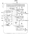
- is a block schematic diagram of a communal metering controller according to the invention;
- Figure 3
- is a block schematic diagram of a single remote measurement module of the controller of Figure 2;
- Figure 4
- is a schematic illustration of the control panel of a remote display unit forming part of the system;
- Figure 5
- is a block schematic diagram showing the circuitry of the remote display unit; and
- Figure 6
- is a table showing the display options provided by the remote display unit
- Figure 1 is an overall schematic illustration of a system for controlling the use of electricity by consumers. Although the embodiment described below relates primarily to the supply and control of electricity to consumers, it will be appreciated that other utilities such as gas or water, or even access to radio or television broadcasts can be controlled by the system of the invention. Thus, the word "utility" should be interpreted in a broad sense in this specification as meaning a substance such as gas or water, energy such as electricity, information or data as in the case of a television or music program signal, or another commodity or service which is supplied in a controlled manner to a user thereof.
- In Figure 1, a
vending depot 10 is shown comprising a number ofcomputer terminals 12 connected in a network configuration. The vending depot serves to receive payment from consumers wishing to purchase electricity (or other utilities) and generates credit information which is transmitted via communications means 14 (in the prototype system, a microwave link) to atreasury department 16. - The treasury department includes a computer network with a number of
terminals 18 and adatabase 20 in which transaction details for each consumer are stored. - The system includes a
master control centre 22 which is connected to thevending depot 10 and thetreasury department 16 in a wide area network (WAN), typically via amicrowave link 24, and preferably also via a backup radio link, comprisingtransceivers - The
master control centre 22 communicates via theradio transceiver 28 with a similar radio unit at each ofseveral concentrators 32 which are typically located at electricity substations which supply a predetermined area with electricity. The concentrator collects information from each of a plurality of communal metering controllers or CMC's 34 (described below) which are connected to the substation via amains electricity cable 36 and which comnunicate with the concentrator via power line modems. - In a typical system, each substation might supply electricity to approximately 100 households or consumer sites. Connected to each substation and its respective concentrator would typically be seven
communal metering controllers 34, each of which can control the supply of electricity to up to 20 households orother consumer sites 8. - Referring now to Figure 2, a single
communal metering controller 34 is shown in more detail. Eachcontroller 34 contains a plurality of remote measurement modules 38 (each of which is shown in greater detail in Figure 3), and acontrol circuit 40 which operates together with theremote measurement modules 38 to control the supply of electricity to each consumer site 8 (up to a maximum of 32). - The control circuit or
controller 40 includes amains modem 42, a microcontroller ormicroprocessor 44 with associatedROM 46 andRAM 48 and asystem clock 50. The controller also includestamper detection circuitry 52. Both thecontroller 40 and the remote measurement modules are fed with a 12 volt DC supply from apower supply circuit 54, and communicate via an RS 485bus 56. - As best seen in Figure 3, each
remote measurement module 38 comprises acurrent transformer 58 and acontactor 60 arranged in series with a "live in"terminal 62 and a "live out"terminal 64. The secondary of thecurrent transformer 58 is connected to a power/current measurement circuit 66 which is in turn connected to amicrocontroller 68. The microcontroller is connected to an RS 485interface circuit 70 to allow communication with thecontroller 40. Alocal LED indicator 72 is connected to themicrocontroller 68 to allow monitoring of current consumption. - The current transformer measures the electricity current consumption of the household or consumer site supplied by the particular
remote measurement module 38, with the electrical supply cable to the relevant site being connected via the respective module. Themeasurement circuit 66 measures the current and the voltage for each individual consumer, calculates the power consumption and passes the relevant data to themicrocontroller 68, which in turn passes the data via the RS 485interface 70 to thecommunal metering controller 34. - The
microcontroller 68 also outputs pulses to thelocal LED 72. The frequency of the output pulses to the LED is proportional to the power being used by the consumer. ThisLED 72 is used to calibrate the meter for accuracy as well as to give an indication that the measuring circuits are in good working order. All the relevant data concerning theremote measuring module 38 are stored locally in an EEPROM. - The locally stored data includes as a minimum the following:
- 1. A unique identification number as well as a module address.
- 2. Consumption data for electricity, water and gas.
- 3. Data of installation and whether the meter has been replaced since initial installation.
- 4. Tamper information which includes tamper information from the remote display unit
- 5. Connect/disconnect information.
- 6. Information as to whether the internal contactor has been by-passed i.e. the consumer circuits are live but the internal contactor is open (the supply is disconnected).
- 7. A security algorithm to ensure secure communications as well as error detection and correction.
- The
microcontroller 68 stores a unique identification number and a module address code, allowing the consumption data derived from a particular consumer site to be related to that site and to the credit data corresponding thereto. - The
control circuit 40 of eachcommunal metering controller 34 monitors the consumption information output by themicrocontroller 68 of theremote measurement modules 38, and compares this data with the credit data corresponding to each consumer site which has been received from themaster control centre 22 via theconcentrator 32. When the credit corresponding to a particular consumer site is exhausted, thecontroller 40 sends a command signal to the respectiveremote measurement module 38, themicrocontroller 68 of Which operates thecontactor 60 to disconnect the electricity supply to that consumer site. This command signal can be generated locally as described above, or can be generated at themaster control centre 22, and can be generated manually instead of automatically. - Each communal metering controller is located in a housing which is remote from the consumer sites or households which it supplies. For example, the housing could be mounted at the top of an electricity supply pole, in a building such as a substation, or in a purpose-built enclosure. In any event, all of the measurement and control circuitry required to supply electricity to the consumer site is centralised so that it is only necessary for a supply cable to run from the communal metering controller to each consumer site. The circuit breaker or contactor which controls the electricity supply to each consumer site is also located together with the measurement circuitry, so that it is not accessible to the consumer. This reduces the possibility of tampering with the electricity supply.
- At each consumer site is a
remote display unit 73. The front panel of the display unit is illustrated schematically in Figure 4, while the circuitry thereof is illustrated schematically in Figure 5. The remote display unit has amicroprocessor controller 74 connected to amains modem 76 which is arranged to be plugged into the mains electrical supply at the consumer site and which allows communication between the remote display unit and thecommunal metering controller 34 which controls the supply of electricity to that consumer site, via themains modem 42. - The remote display unit also has a
display 78 which is typically an LCD or LED display with at least eight characters and eight annunciator symbols. - The display unit also has a
keypad 80 to allow data input by the consumer and a pair of LED's 82 and 84, the first of which is illuminated to show a "low credit" condition, and the second flashing to indicate the rate of electricity consumption. - The
mains modem 76 of the remote display unit communicates with thecommunal metering controller 34 using spread spectrum communication techniques in the 20 to 90 kHz band, or 100 kHz to 400 kHz, for example, depending on local regulations. - As shown in Figure 6, selecting various display options using the keypad allows the user to display the available credit, both in electricity units or in monetary terms, the total amount of electricity used to date, the present rate of electricity consumption and a number of other variables. In addition, the provision of a
keypad 80, together with the communication function provided by themicroprocessor 74 and themodem 76 allows theremote display unit 73 to be used as a communication terminal by the consumer. - Thus, the display unit is not limited to displaying status information transmitted by the
controller 40 of thecommunal metering controller 34, but can be used by the consumer to communicate with themaster control centre 22, for example. This feature can be used to allow the consumer to make payments to the utility supplier. A secret code or PIN can be allocated to the consumer, who can then initiate communication with the master control centre, enter the PIN, enter a credit card number, and then indicate the amount of credit which he or she wishes to purchase for that particular utility. Alternatively, the consumer can have an account with the utility supplier which is adjusted when a credit is purchased and which is paid conventionally. In either case, when an additional credit is purchased, new credit data is generated by the utility supplier and transmitted back from the master control centre to therelevant controller 40, and from there to therelevant display unit 73, either directly or in response to an enquiry. - The
microprocessor 74 of theremote display unit 73 is configured to have twooutput circuits 86 and 87 which indepentently controlexternal circuit breakers circuit breakers - The
microprocessor 74 is also configured to have two inputs 88 and 89. Input 88 is used to monitor water consumption and input 89 to monitor gas consumption. Both inputs 88 and 89 monitor the circuits connected to them to ensure that the entire system is healthy and in fully operational condition. If the monitored circuits become defective in any way, themicroprocessor 74 immediately sends an alarm to thecommunal metering controller 34 via the mains modems 76 and 42. From thecommunal metering controller 34, the alarm is sent to theconcentrator 32 and finally to themaster controller 22. The alarms are annunciated at all places and at all stages of the system. - The consumption data for both water and gas is processed in the
microprocessor 74 and then sent to thecommunal metering controller 34, which in turn sends this data to theconcentrator 32, which then finally sends it to themaster controller 22. - In addition to the above, the
remote display unit 73 has the functional facility to be equipped with another 8 input/outputs, one of which can be used for afire alarm 90. Another can be used for asecurity alarm 91 and the remainder, 92 to 97, can be customised to meet the needs of the consumer, e.g. for household automation. - It will be appreciated that the use of the use of the
remote display unit 73 is not essential to the basic operation of the utility control system, since the actual control and measurement function is carried out remotely from the consumer site, by thecommunal metering controllers 34. However, the provision of the remote display unit allows the consumer to obtain information as to the status of the utility supply, and also allows communication with the utility supplier. Such communication is particularly advantageous when used to allow the consumer to purchase credit for further supplies of the utility. The remote display unit can be installed anywhere at the consumer site, since it has no direct physical link to thecommunal metering controller 34, but communicates instead via the mains supply into which it is plugged.
Claims (18)
- A method of controlling the use of a utility at a consumer site characterised in that it comprises:supplying the utility to the consumer site via metering means located at a metering site remote from the consumer site;monitoring, at the metering site, consumption of the utility at the consumer site;generating display data at the metering site corresponding to the consumption of the utility;transmitting the display data to display means at the consumer site; andgenerating a display at the consumer site from the display data, indicative of the consumption of the utility.
- A method according to claim 1 characterised in that consumption of the utility at a plurality of consumer sites is measured by respective separate measurement modules located at the metering site.
- A method according to claim 2 characterised in that consumption data generated by the respective measurement modules is output to a common control circuit which generates the display data for transmission to the display means at respective consumer sites.
- A method according to any one of claims 1 to 3 characterised in that the display data is transmitted via electrical supply cables running between the metering site and the consumer sites.
- A method according to any one of claims 1 to 4 characterised in that it includes storing credit data for each consumer site at the metering site, reducing the value of a credit represented by the data in accordance with consumption of the utility at each consumer site, and operating the respective metering means to interrupt the supply of the utility to each consumer site when the credit value reaches a predetermined value.
- A method according to claim 5 characterised in that the credit data is generated at a control centre and transmitted to the metering site.
- A method according to claim 6 characterised in that the credit data is transmitted to respective ones of a plurality of metering sites from the control centre via wireless radio transmission and/or electrical supply cables.
- A method according to any one of claims I to 7 characterised in that it includes transmitting enquiry data from display means at the consumer site to the metering means at the metering site.
- A method according to claim 8 characterised in that the enquiry data comprises a status request made by a consumer to the metering means, the metering means transmitting display data and transmitting it to the display means in response to the status request.
- A method according to claim 8 or claim 9 characterised in that the enquiry data comprises a credit request made by a consumer to a utility supplier, the credit request data being transmitted via the metering means to a central control centre, a further credit being allocated to the consumer at the control centre, and new credit data being transmitted from the control centre to the metering site.
- A system for controlling the use of a utility at a consumer site characterised in that it comprises:metering means located at a metering site remote from at least one consumer site and arranged to control the supply of a utility to the at least one consumer site;monitoring means located at the metering site arranged to monitor the consumption of the utility at the consumer site and to generate display data corresponding to the consumption of the utility;first communication means for transmitting the display data to the consumer site; anddisplay means located at the consumer site and responsive to the display data to generate a display indicative of the consumption of the utility.
- A system according to claim 11 characterised in that the monitoring means comprises a plurality of separate measurement modules and a common control circuit which receives utility consumption data from each measurement module and outputs control signals thereto.
- A system according to claim 12 characterised in that the control circuit includes data storage means for storing data corresponding to respective consumers, including at least identification data, credit data corresponding to a current credit value, and utility consumption data; and processor means for calculating a current credit value from a previous credit value and the utility consumption data.
- A system according to claim 11 or 12 characterised in that the display means comprises second communication means for receiving a signal containing the display data from the first communication means, processor means for extracting the display data from the received signal, and a display module for displaying the display data in a discernible form.
- A system according to any one of claims 11 to 14 characterised in that the display means includes data input means connected to the processor means and operable by a user thereof to input enquiry data comprising a status request, the second communication means being adapted to transmit the enquiry data to the first communication means of the monitoring means, and the monitoring means being responsive to the enquiry data to transmit display data to the display means.
- A system according to claim 15 characterised in that the first communication means is further adapted to receive enquiry data comprising a credit request from the display means, to transmit the enquiry data to a control centre, to receive new credit data from the control centre, and to store a new credit value correponding to the new credit data.
- A system according to claim 16 characterised in that the first communication means is further adapted to transmit the new credit data to the display means.
- A system according to any one of claims 14 to 17 characterised in that the first and second communication means comprise mains modems which communicate via electrical supply cables running between the metering station and the consumer sites.
Applications Claiming Priority (2)
| Application Number | Priority Date | Filing Date | Title |
|---|---|---|---|
| ZA957562 | 1995-09-08 | ||
| ZA9507562 | 1995-09-08 |
Publications (2)
| Publication Number | Publication Date |
|---|---|
| EP0762350A2 true EP0762350A2 (en) | 1997-03-12 |
| EP0762350A3 EP0762350A3 (en) | 1998-08-05 |
Family
ID=25585297
Family Applications (1)
| Application Number | Title | Priority Date | Filing Date |
|---|---|---|---|
| EP96306543A Withdrawn EP0762350A3 (en) | 1995-09-08 | 1996-09-09 | Communal metering system |
Country Status (2)
| Country | Link |
|---|---|
| US (1) | US5959549A (en) |
| EP (1) | EP0762350A3 (en) |
Cited By (10)
| Publication number | Priority date | Publication date | Assignee | Title |
|---|---|---|---|---|
| GB2323695A (en) * | 1997-03-26 | 1998-09-30 | Schneider Electric Sa | Prepayment utility supply system |
| WO2000013291A1 (en) * | 1998-08-27 | 2000-03-09 | Horst Ziegler | System for controlling consumption of a medium, especially a mains-connected medium |
| WO2000051094A1 (en) * | 1999-02-26 | 2000-08-31 | Amatsia Kashti | Interface unit for providing bidirectional communication between utility company and user |
| WO2000058919A1 (en) * | 1999-03-26 | 2000-10-05 | Merlin Gerin S.A. (Proprietary) Limited | Deferred prepayment for utility services |
| EP1079343A2 (en) * | 1999-08-27 | 2001-02-28 | Deutsche Zählergesellschaft Nachf. A. Stepper & Co. mbH | Distribution system for supplying a commodity, such as power, heating, gas or water, to end-users and method for operating the system |
| WO2001099465A2 (en) * | 2000-06-19 | 2001-12-27 | Intrinzix Technologies, Inc. | Hybrid bi-directional communication system for monitoring a power delivery system |
| FR2834408A1 (en) * | 2001-12-28 | 2003-07-04 | Roiret Entpr S | ELECTRONIC INFORMATION MANAGEMENT AND DISTRIBUTION SYSTEM OF PRODUCT (S) AND / OR SERVICE (S) IN NETWORK (X). |
| FR2837961A1 (en) * | 2002-04-02 | 2003-10-03 | Rohl | Secure management system for travelers sites incorporates distribution points for water and electricity together with a communications interface that allows collection of payments using an electronic purse with credit units |
| WO2003101143A1 (en) * | 2002-05-27 | 2003-12-04 | Merlin Gerin S.A. (Proprietary) Limited | Remote metering system |
| BE1019385A4 (en) * | 2010-06-23 | 2012-06-05 | Xemex Nv | CONSUMPTION METER WITH COMMUNICATION MODULE. |
Families Citing this family (26)
| Publication number | Priority date | Publication date | Assignee | Title |
|---|---|---|---|---|
| IT1295471B1 (en) * | 1997-10-03 | 1999-05-12 | Taglioni Communications S A S | SYSTEM FOR DETECTION OF DOMESTIC CONSUMPTION OF ELECTRICITY, THERMAL ENERGY, WATER AND GAS. |
| JP3780130B2 (en) * | 1998-11-16 | 2006-05-31 | キヤノン株式会社 | Power consumption management device |
| US6747571B2 (en) * | 1999-03-08 | 2004-06-08 | Comverge Technologies, Inc. | Utility meter interface system |
| US6553353B1 (en) * | 2000-01-28 | 2003-04-22 | John Joseph Littlejohn | Advanced metering system enabling regulation and billing of utilities by third party interagent |
| GB2364420B (en) * | 2000-05-22 | 2002-11-20 | Secure Electrans Ltd | A prepayment utility metering system |
| US8725657B2 (en) * | 2000-05-22 | 2014-05-13 | Secure Electrans Limited | Utility metering system incorporating a transaction authorisation system |
| US6597881B2 (en) | 2000-10-16 | 2003-07-22 | Ricoh Company, Ltd. | Image forming apparatus |
| EP1340311A2 (en) * | 2000-11-06 | 2003-09-03 | BCN Data Systems | Auxiliary metering apparatus and methods |
| US6906637B2 (en) * | 2001-10-29 | 2005-06-14 | Landis + Gyr, Inc. | Utility disconnect controller |
| US7945471B2 (en) * | 2001-11-02 | 2011-05-17 | Mckinney Jerry L | Monitoring system communication system and method |
| US7230544B2 (en) * | 2002-04-22 | 2007-06-12 | Cellnet Innovations, Inc. | Intelligent two-way telemetry |
| US20040225626A1 (en) * | 2003-05-07 | 2004-11-11 | Brian Forrester | Automated meter reading installation system and method |
| US20040243525A1 (en) * | 2003-05-07 | 2004-12-02 | Brian Forrester | System and method for disconnecting utility services |
| US7554459B2 (en) * | 2003-07-17 | 2009-06-30 | Enel Distribuzione S.P.A. | Method and system for remote updates of meters for metering the consumption of electricity, water or gas |
| GR1004981B (en) * | 2003-11-06 | 2005-09-09 | �������������� �������� ����������� ��� ��������� ������� (����) � | Remote control management of products and services |
| MXPA04010077A (en) * | 2004-10-13 | 2006-05-03 | Iusa Sa De Cv | Prepayment system for electric power meters using a contactless smart card with an automatic supply cut-off device. |
| US20060230423A1 (en) * | 2005-04-11 | 2006-10-12 | Doug Burgett | System and method for providing calibration/verification services at a CATV service organization site on a prepaid basis |
| US7333903B2 (en) | 2005-09-12 | 2008-02-19 | Acuity Brands, Inc. | Light management system having networked intelligent luminaire managers with enhanced diagnostics capabilities |
| US7817063B2 (en) | 2005-10-05 | 2010-10-19 | Abl Ip Holding Llc | Method and system for remotely monitoring and controlling field devices with a street lamp elevated mesh network |
| US7623043B2 (en) * | 2005-12-19 | 2009-11-24 | General Electric Company | Method and system for metering consumption of energy |
| NZ549548A (en) * | 2006-08-31 | 2009-04-30 | Arc Innovations Ltd | Managing supply of a utility to a customer premises |
| US20080065428A1 (en) * | 2006-09-07 | 2008-03-13 | Tyler Duffy | Automated Campground System |
| US8085164B2 (en) | 2006-12-13 | 2011-12-27 | Blueline Innovations | Apparatus and method for monitoring a variety of resource consumption meters |
| US7961554B2 (en) * | 2008-01-11 | 2011-06-14 | Cellnet Innovations, Inc. | Methods and systems for accurate time-keeping on metering and other network communication devices |
| US8140276B2 (en) | 2008-02-27 | 2012-03-20 | Abl Ip Holding Llc | System and method for streetlight monitoring diagnostics |
| US9900667B2 (en) * | 2011-06-14 | 2018-02-20 | Energycomnetwork, Inc. | Systems and methods for authorized connection of utility service |
Family Cites Families (9)
| Publication number | Priority date | Publication date | Assignee | Title |
|---|---|---|---|---|
| GB2042777B (en) * | 1979-02-21 | 1983-05-11 | South Eastern Elec Board | Electrical energy consumption meter |
| US4933633A (en) * | 1981-06-09 | 1990-06-12 | Adec, Inc. | Computer controlled energy monitoring system |
| US4804957A (en) * | 1985-11-27 | 1989-02-14 | Triad Communications, Inc. | Utility meter and submetering system |
| US4803632A (en) * | 1986-05-09 | 1989-02-07 | Utility Systems Corporation | Intelligent utility meter system |
| US4731575A (en) * | 1986-12-08 | 1988-03-15 | Sloan Joseph W | Prepayment metering system using encoded purchase cards |
| US4924404A (en) * | 1988-04-11 | 1990-05-08 | K. Reinke, Jr. & Company | Energy monitor |
| BR9202095A (en) * | 1992-06-01 | 1994-03-01 | Pesquisas De En Eletrica Cepel | EQUIPMENT FOR MEDICATION, LEUTURE AND BILLING CENTRALIZED IN THE CONSUMPTION OF ELECTRIC ENERGY |
| DE4243092C2 (en) * | 1992-12-18 | 1996-03-14 | Ludwig Kreuzpaintner | Power distribution system |
| US5699276A (en) * | 1995-12-15 | 1997-12-16 | Roos; Charles E. | Utility meter providing an interface between a digital network and home electronics |
-
1996
- 1996-09-09 EP EP96306543A patent/EP0762350A3/en not_active Withdrawn
- 1996-09-09 US US08/709,580 patent/US5959549A/en not_active Expired - Fee Related
Non-Patent Citations (1)
| Title |
|---|
| None |
Cited By (16)
| Publication number | Priority date | Publication date | Assignee | Title |
|---|---|---|---|---|
| GB2323695B (en) * | 1997-03-26 | 2001-01-10 | Schneider Electric Sa | Prepayment utility supply system |
| GB2323695A (en) * | 1997-03-26 | 1998-09-30 | Schneider Electric Sa | Prepayment utility supply system |
| WO2000013291A1 (en) * | 1998-08-27 | 2000-03-09 | Horst Ziegler | System for controlling consumption of a medium, especially a mains-connected medium |
| GB2362472B (en) * | 1999-02-26 | 2003-10-08 | Amatsia Kashti | Interface unit for providing bidirectional communication between utility company and user |
| GB2362472A (en) * | 1999-02-26 | 2001-11-21 | Amatsia Dr Kashti | Interface unit for providing bidirectional communication between utility company and user |
| WO2000051094A1 (en) * | 1999-02-26 | 2000-08-31 | Amatsia Kashti | Interface unit for providing bidirectional communication between utility company and user |
| WO2000058919A1 (en) * | 1999-03-26 | 2000-10-05 | Merlin Gerin S.A. (Proprietary) Limited | Deferred prepayment for utility services |
| EP1079343A2 (en) * | 1999-08-27 | 2001-02-28 | Deutsche Zählergesellschaft Nachf. A. Stepper & Co. mbH | Distribution system for supplying a commodity, such as power, heating, gas or water, to end-users and method for operating the system |
| EP1079343A3 (en) * | 1999-08-27 | 2004-03-17 | Martin Dr.-Ing. Wisy | Distribution system for supplying a commodity, such as power, heating, gas or water, to end-users and method for operating the system |
| WO2001099465A2 (en) * | 2000-06-19 | 2001-12-27 | Intrinzix Technologies, Inc. | Hybrid bi-directional communication system for monitoring a power delivery system |
| WO2001099465A3 (en) * | 2000-06-19 | 2002-05-16 | Intrinzix Technologies Inc | Hybrid bi-directional communication system for monitoring a power delivery system |
| FR2834408A1 (en) * | 2001-12-28 | 2003-07-04 | Roiret Entpr S | ELECTRONIC INFORMATION MANAGEMENT AND DISTRIBUTION SYSTEM OF PRODUCT (S) AND / OR SERVICE (S) IN NETWORK (X). |
| WO2003060840A1 (en) * | 2001-12-28 | 2003-07-24 | Roiret Entreprises S.A. | Electronic system for data management and product and/or service distribution over network(s) |
| FR2837961A1 (en) * | 2002-04-02 | 2003-10-03 | Rohl | Secure management system for travelers sites incorporates distribution points for water and electricity together with a communications interface that allows collection of payments using an electronic purse with credit units |
| WO2003101143A1 (en) * | 2002-05-27 | 2003-12-04 | Merlin Gerin S.A. (Proprietary) Limited | Remote metering system |
| BE1019385A4 (en) * | 2010-06-23 | 2012-06-05 | Xemex Nv | CONSUMPTION METER WITH COMMUNICATION MODULE. |
Also Published As
| Publication number | Publication date |
|---|---|
| US5959549A (en) | 1999-09-28 |
| EP0762350A3 (en) | 1998-08-05 |
Similar Documents
| Publication | Publication Date | Title |
|---|---|---|
| US5959549A (en) | Communal metering system | |
| US5664202A (en) | Intelligent power consumption monitoring and control system | |
| US5635895A (en) | Remote power cost display system | |
| EP0015120B1 (en) | Meters for measuring electrical energy consumption | |
| KR20100125809A (en) | Smart cabinet panel and method for building management using the same panel | |
| US5831550A (en) | System and process for the measurement of the electric energy consumption of a plurality of consumers | |
| KR20040078648A (en) | System for the remote data acquisition and control of electric energy meters | |
| KR19980701245A (en) | ENERGY MANAGEMENT AND BUILDING AUTOMATION SYSTEM | |
| EP0419106B1 (en) | Commodity metering systems | |
| JPS62128398A (en) | Service value measuring apparatus for utility equipment | |
| JP3233521B2 (en) | Grid-connected inverse converter | |
| US20130307694A1 (en) | Electricity/power metering system and method | |
| GB2280961A (en) | Commodity metering apparatus | |
| US20110187557A1 (en) | Method and arrangement for measuring electrical usage and curtailing electrical usage of individual electrical components | |
| EP0981723B1 (en) | Metering systems | |
| GB2374760A (en) | Transmitting utility meter measurements by mobile telephone | |
| KR100725178B1 (en) | Intelligent power service system using plc | |
| AU722511B2 (en) | Communal metering system | |
| KR20100037910A (en) | Distributing board that power rates are displayed | |
| GB2302952A (en) | Electrical power consumption control and evaluation system | |
| JP2784354B2 (en) | Saving rate display | |
| KR20210042593A (en) | Transformer load monitoring system using metering of dcu | |
| JP2002092735A (en) | Energy management system | |
| KR200432760Y1 (en) | Monitoring Device of Maximum Electric Power Demand | |
| RU2193812C2 (en) | Device for on-line control of electrical energy supply and consumption in ac power mains |
Legal Events
| Date | Code | Title | Description |
|---|---|---|---|
| PUAI | Public reference made under article 153(3) epc to a published international application that has entered the european phase |
Free format text: ORIGINAL CODE: 0009012 |
|
| AK | Designated contracting states |
Kind code of ref document: A2 Designated state(s): AT BE CH DE DK ES FI FR GB GR IE IT LI LU MC NL PT SE |
|
| AX | Request for extension of the european patent |
Free format text: AL PAYMENT 961007;LT PAYMENT 961007;LV PAYMENT 961007;SI PAYMENT 961007 |
|
| PUAL | Search report despatched |
Free format text: ORIGINAL CODE: 0009013 |
|
| AK | Designated contracting states |
Kind code of ref document: A3 Designated state(s): AT BE CH DE DK ES FI FR GB GR IE IT LI LU MC NL PT SE |
|
| AX | Request for extension of the european patent |
Free format text: AL PAYMENT 961007;LT PAYMENT 961007;LV PAYMENT 961007;SI PAYMENT 961007 |
|
| STAA | Information on the status of an ep patent application or granted ep patent |
Free format text: STATUS: THE APPLICATION IS DEEMED TO BE WITHDRAWN |
|
| 18D | Application deemed to be withdrawn |
Effective date: 19990206 |