EP0763370B1 - Katheterisierungsbesteck - Google Patents
Katheterisierungsbesteck Download PDFInfo
- Publication number
- EP0763370B1 EP0763370B1 EP96118183A EP96118183A EP0763370B1 EP 0763370 B1 EP0763370 B1 EP 0763370B1 EP 96118183 A EP96118183 A EP 96118183A EP 96118183 A EP96118183 A EP 96118183A EP 0763370 B1 EP0763370 B1 EP 0763370B1
- Authority
- EP
- European Patent Office
- Prior art keywords
- catheter
- cannula
- puncture
- steel needle
- capillary
- Prior art date
- Legal status (The legal status is an assumption and is not a legal conclusion. Google has not performed a legal analysis and makes no representation as to the accuracy of the status listed.)
- Expired - Lifetime
Links
Images


Classifications
-
- A—HUMAN NECESSITIES
- A61—MEDICAL OR VETERINARY SCIENCE; HYGIENE
- A61M—DEVICES FOR INTRODUCING MEDIA INTO, OR ONTO, THE BODY; DEVICES FOR TRANSDUCING BODY MEDIA OR FOR TAKING MEDIA FROM THE BODY; DEVICES FOR PRODUCING OR ENDING SLEEP OR STUPOR
- A61M25/00—Catheters; Hollow probes
- A61M25/01—Introducing, guiding, advancing, emplacing or holding catheters
- A61M25/06—Body-piercing guide needles or the like
- A61M25/0612—Devices for protecting the needle; Devices to help insertion of the needle, e.g. wings or holders
- A61M25/0637—Butterfly or winged devices, e.g. for facilitating handling or for attachment to the skin
-
- A—HUMAN NECESSITIES
- A61—MEDICAL OR VETERINARY SCIENCE; HYGIENE
- A61B—DIAGNOSIS; SURGERY; IDENTIFICATION
- A61B17/00—Surgical instruments, devices or methods, e.g. tourniquets
- A61B17/34—Trocars; Puncturing needles
- A61B17/3415—Trocars; Puncturing needles for introducing tubes or catheters, e.g. gastrostomy tubes, drain catheters
-
- A—HUMAN NECESSITIES
- A61—MEDICAL OR VETERINARY SCIENCE; HYGIENE
- A61M—DEVICES FOR INTRODUCING MEDIA INTO, OR ONTO, THE BODY; DEVICES FOR TRANSDUCING BODY MEDIA OR FOR TAKING MEDIA FROM THE BODY; DEVICES FOR PRODUCING OR ENDING SLEEP OR STUPOR
- A61M25/00—Catheters; Hollow probes
- A61M25/01—Introducing, guiding, advancing, emplacing or holding catheters
- A61M25/06—Body-piercing guide needles or the like
- A61M25/0606—"Over-the-needle" catheter assemblies, e.g. I.V. catheters
Definitions
- the invention relates to a catheterization kit for catheter placement in a blood vessel, consisting of a puncture cannula with a cannula hub, which has a handle device, the one Puncture cannula surrounding catheter with a catheter hub, and a guide wire that is in the lumen of the Puncture cannula is axially displaceable.
- indwelling cannulas For measuring pressure in vessels (arterial blood pressure) and for the administration of infusions and blood samples need to puncture arteries and central veins and so-called indwelling cannulas are placed, which as short catheters are designed with a catheter hub, to which a liquid transfer device can be connected is. There is a puncture cannula in the catheter, their sharpened tip over the front end the catheter protrudes somewhat. Such cutlery is known from US-A-3 312 220. Thus, when puncturing the Transition from the puncture cannula to the thicker catheter done gradually, is the tip of the catheter bevelled on the outside.
- the stepless connection of the catheter to the outer circumference of the puncture cannula does not have the disadvantages of puncture hole expansion and difficulty penetrating the skin and to avoid vessel wall, which the precision of the puncture reduce.
- the latter is reinforced by the fact that a handle device is missing from this cutlery, so that it can be touched directly on the cylindrical cannula attachment must and can only be held here uncertainly.
- the puncture is carried out with the guide wire withdrawn, thus blood in the puncture cannula if the puncture is successful flows back and into the transparent cannula hub reached.
- the cutlery since the cutlery is attached to this cannula attachment is held, the fingers cover it and the blood leak will not or only late in the cannula attachment discovered. Even with this cutlery it is unfavorable that not only the puncture cannula during vascular puncture, but also the surrounding catheter the puncture hole must penetrate. The skin penetrates jerky due to skin resistance and the exact Placement of the puncture cannula tip in the vessel difficult or often impossible.
- a certain improvement in the determination of puncture success comes with cutlery according to US-A-48 94 052 achieved, especially for arterial puncture is determined.
- the catheter of this cutlery consists of clear plastic material and in the through the Catheter pushed through, only with the section section the tip portion protruding over the catheter A guide wire is slidably provided for the puncture cannula.
- the puncture cannula has a hole on the side, that with ready-to-use catheterization kits is behind the end of the catheter, d. H. of this is enclosed. If the puncture is successful, blood penetrates the hole in an annular space between the puncture cannula and transparent catheter and is ascending towards of the approaches visible through the catheter.
- DE-U-89 14 941 is a catheterization set known that besides a steel cannula and a plastic capillary has a dilator sleeve.
- the dilator sleeve is pushed onto the steel cannula and The plastic capillary is pushed over them.
- This Catheterization equipment is used to make large-lumen vascular catheters through the plastic capillary into the blood vessel introduce.
- the puncture hole is the small-lumen steel cannula surrounded by the relatively thick dilator sleeve. From the Dilator sleeve and the plastic capillary pushed onto it protrudes the steel cannula.
- the invention is based on the object Catheterization set made of steel needle, capillary and Guide wire to create a catheter lay with high accuracy according to different introduction methods enables.
- the Puncture of the artery or vein is only with the bare steel part of the steel needle free of the capillary performed, whereby a precise puncture of the Vessel is possible.
- the capillary on the steel needle does not penetrate the skin at first.
- a "step" on the circumference of the steel needle happens Skin penetration practically smooth and straight, so that the steel needle tip on the desired by the user Place is placed.
- The is accordingly exact Guidewire to the destination and the catheter relocated.
- the hole in the steel needle can be drilled, be ground or punched. It is preferably in the immediate vicinity of the tip of the catheter, so the bare steel needle section essentially over its entire length used as a puncture element can be.
- the hole size should be measured in this way be that the blood leakage is noticeable, a running out of larger amounts of blood is avoided.
- the catheterization kit after Claim 1 is further improved according to the invention that after the placement of the catheter, in particular in an artery, preventing blood reflux, however, a simple connection of a transmission device is possible.
- valve body with a self-closing Passage arranged.
- the passage in the valve body enables punch-free passage of the puncture cannula with internal guidewire. If after the puncture cannula and the guide wire have been pulled out of the catheter, the passage of the valve body closes and it does not come to the backflow of blood from the catheter hub.
- the catheter can rest on the patient's skin be attached, e.g. B. sewn with the help of wings without the artery being pulled off got to.
- the valve body advantageously consists of a Elastomer disc with at least one slot, and it it is provided that a connectable to the catheter hub A coaxial hose connector tubular open holder that supports the slot penetrates.
- the one that can be connected directly to the catheter hub Connection piece effects over the tubular Holds open an opening of the valve body in the catheter hub and is flexible over the hose line Connection to a transmission device possible.
- Another handling improvement results from the fact that the hose line at the end facing away from the connector Tap, preferably a three-way tap, which after opening the passage in the valve body Allows fluid or pressure transfer.
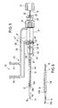
- a catheterization set that is particularly suitable for Suitable for arterial catheterization consists in essentially of three parts, namely a puncture cannula 10, a guidewire 12 and a catheter 13, which - as shown in Fig. 5 - plug together coaxially to let.
- the puncture cannula 10 has one hollow steel needle 11, the front (distal) end 15 is sharpened sharply and at the rear (Proximal) end attached to a cannula hub 16 which contains a continuous channel 17.
- On Outer cone 18 at the transition between the steel needle 11 and the cannula attachment 16 serves as a plug element for Connection to an inner cone of a catheter hub of the catheter 13.
- a blood retention cap 19 with a coaxial narrow passage 20 for guiding the guide wire 12 closes the cannula hub 16 at the rear End from.
- the blood retention cap 19 wears on the rear End a coaxial coupling 22 with a Locking element for a connection.
- a small hole 21 is formed in its wall, that can be drilled, ground or punched from the outside to the lumen of the steel needle 11 goes through.
- a handle device 25 is connected to the cannula attachment 16 of the puncture cannula 10.
- the cannula attachment 16 and the handle device 25 are preferably made of plastic and are produced in one piece.
- the grip device 25 has an arm 26 which runs parallel to the steel needle 11 at a distance next to it.
- the rear (proximal) end of the arm 26 adjoins a tubular main body of the cannula hub 16 via a leg 27 extending at a right angle.
- the width of the leg 27 is substantially equal to the length of the main body. Its extension in the transverse direction determines the distance a between the steel needle 11 and the edge 28 of the arm 26 which is closest to it.
- the main area of the arm 26 is plate-like flat, while its two longitudinal edges 28 and 29 are bead-like reinforced for stabilization.
- two handle plates 30, 31 are formed, which project in the same alignment from the longitudinal edge 29 at right angles to the side.
- the two handle plates 30, 31 form a handle 32 which can be gripped between the thumb and index finger.
- the length of the arm 26 and the attachment of the handle 32 on it are chosen so that the handle 32 is located in the central region of the steel needle 11.
- a preferred distance between the tip 14 and the handle plate 30 is approximately 45 mm.
- the guide wire 12 passable, its diameter is adapted to the lumen diameter and that on his proximal end carries a head 35, which acts as a closure cap trained with internal thread and with a Threaded section of the coupling socket 22 can be locked is.
- the guidewire 12 can be a tightly wound Steel wire can be designed with flexible tip 12a.
- catheterization kit is also available with a guidewire functional, the rear end as is rigid wire and only in the front Part as a helically wound flexible strand body is trained.
- the catheter 13 is a short catheter made of flexible Plastic that can be 45 mm to 50 mm long and made of a capillary 40, at the rear end of a Catheter hub 41 is attached.
- the catheter hub 41 is a piece of pipe that is at the front (distal) end has a flexible kink protection 42 for the capillary 40 and an inner cone at the rear (proximal) end 43 for receiving the outer cone 18 of the puncture cannula 10 and a chamber 44 for housing a Contains valve device.
- On the outside of the catheter hub 41 are two on opposite sides Directional fixing wing 45 attached, the holes 46 for sewing on the patient's skin.
- the rear opening of the catheter hub 41 is from surrounded by an annular flange 47, the coupling elements 48, e.g. B. threaded parts, for connection to a connector has, the further lines to the catheter 13 connects.
- the ring flange 47 is a radial Notch 49 formed, in which an axial pin 33 of the Cannula attachment 16 engages as a rotation lock.
- an elastomeric disc 50 which is made by a Slot or cross slot 51 is penetrated, the Lips lie close together and the channel of the catheter 13 lock off to the rear.
- the catheter is for transport in sterile packaging 13 attached to the puncture cannula 10 and through Engagement of the outer cone 18 with the inner cone 43 committed to this.
- the steel needle 11 projects beyond with a section 11a Tip 40a of the capillary 40 by preferably 20 mm and the hole 21 is exposed in front of the capillary tip 40a (Fig. 5).
- the guidewire 12 is through the puncture cannula 10 pushed through and protrudes from the grinding end 15 the steel needle 11 a bit before.
- An unsigned one Protective cap covers those to be inserted into the patient Puncture elements.
- the guide wire 12 is withdrawn for puncture until a mark made on the guide wire 12 23 with the rear edge of the blood retention cap 19 matches in length and its tip 12a behind the hole 21 of the steel needle 11 is located (Fig. 5).
- the catheterization kit is on the angled handle 32 detected and it is the steel needle 11 exclusively with their bare from the capillary 40 bare Insert part 11a into a blood vessel. Hole 21 remains visible outside the injection site. The successful one Puncture is due to blood leakage from the hole 21 immediately recognizable. Then the guidewire 12 advanced into the vessel and its headpiece 35 with the blood retention cap attached to the cannula hub 16 19 locked. The feed of the guide wire 12 closes the hole 21 and stops the blood from escaping.
- a backflow of blood is also from the guidewire 12 largely prevented, as a result of this its diameter adapted to the lumen of the steel needle 11 is effective as a lumen closure.
- the capillary 40 can be withdrawn somewhat from the puncture hole Steel needle 11 and the guide wire 12 in it Be pushed. Then the steel needle 11 with the inner guide wire 12 in pulled out of the catheter 13.
- the catheter 13 is by means of the fixing wing 45 is sewn onto the patient's skin, so that the tip 40a of the capillary 40 in the correct position within the vessel is.
- a transmission device For connecting a transmission device to the catheter 13 serves a flexible hose line 56, one of which End of a housing of a three-way valve 57 with one or Outputs B and C carries (Fig. 7).
- a connector 52 At the other end of the Hose line 56 is a connector 52, an internal thread 53 for screwing onto the coupling elements 48 of the ring flange 47 of the catheter hub 41 has.
- the open holder 55 with very small dimensions penetrates in the connected state of the parts 41 and 52 the cross recess 51 of the elastomer disc 50 and holds the valve body 50 to flow through a liquid open.
Description
- Fig. 1
- drei Bestandteile eines Katheterisierungsbestecks, die im Anwendungszustand koaxial zusammengesteckt sind,
- Fig. 2
- eine Ansicht in Richtung des Pfeils II in Fig. 1,
- Fig. 3
- eine Ansicht in Richtung des Pfeils III in Fig. 1,
- Fig. 4
- eine Draufsicht auf eine Ventilscheibe für den Katheteransatz,
- Fig. 5
- eine Draufsicht auf das anwendungsbereite Katheterisierungsbesteck,
- Fig. 6
- das vordere Ende des Katheterisierungsbestecks in vorgeschrittenem Anwendungsstadium, und
- Fig. 7
- den im Gefäß verlegten und auf der Haut festgenähten Katheter kurz vor der Öffnung des Ventils im Katheteransatz durch einen Offenhalter an einer Anschlußvorrichtung.
Claims (5)
- Katheterisierungsbesteck für die Katheterverlegung in einem Blutgefäß, bestehend aus einer Punktionskanüle (10) mit einer Stahlnadel (11) und einem Kanülenansatz (16),dadurch gekennzeichnet, daß im Zusammenbau-Zustand die Stahlnadel (11) mit einem Abschnitt (11a) die Spitze (40a) des Kapillars (40) mm 15 mm bis 25 mm, vorzugsweise mm 20 mm, überragt.einem die Stahlnadel (11) umgebenden Kapillar (40) mit einem Katheteransatz (41),und einem Führungsdraht (12), der in dem Lumen der Stahlnadel (11) axial verschiebbar ist,
- Katheterisierungsbesteck nach Anspruch 1, dadurch gekennzeichnet, daß in der Wand der Stahlnadel (11) distal von der Spitze (40a) des Kapillars (40) ein Loch (21) ausgebildet ist.
- Katheterisierungsbesteck nach Anspruch 1 oder 2, dadurch gekennzeichnet, daß in dem Katheteransatz (41) ein Ventilkörper mit einem selbstschließenden Durchlaß angeordnet ist.
- Katheterisierungsbesteck nach Anspruch 3, dadurch gekennzeichnet, daß der Ventilkörper aus einer Elastomerscheibe (50) mit mindestens einem Schlitz (51) besteht und daß ein mit dem Katheteransatz (41) verbindbares Anschlußstück (52) einer Schlauchleitung (50) einen koaxialen rohrförmigen Offenhalter (55) trägt, der den Schlitz (51) der Elastomerscheibe (50) durchdringt.
- Katheterisierungsbesteck nach Anspruch 4, dadurch gekennzeichnet, daß die Schlauchleitung (50) an dem dem Anschlußstück (52) abgewandten Ende einen Hahn (57), vorzugsweise einen Dreiwegehahn, aufweist.
Applications Claiming Priority (3)
| Application Number | Priority Date | Filing Date | Title |
|---|---|---|---|
| DE9215927 | 1992-11-24 | ||
| DE9215927U | 1992-11-24 | ||
| EP93922943A EP0624104B1 (de) | 1992-11-24 | 1993-10-13 | Katheterisierungsbesteck |
Related Parent Applications (2)
| Application Number | Title | Priority Date | Filing Date |
|---|---|---|---|
| EP93922943A Division EP0624104B1 (de) | 1992-11-24 | 1993-10-13 | Katheterisierungsbesteck |
| EP93922943.1 Division | 1994-06-09 |
Publications (3)
| Publication Number | Publication Date |
|---|---|
| EP0763370A2 EP0763370A2 (de) | 1997-03-19 |
| EP0763370A3 EP0763370A3 (de) | 1997-04-16 |
| EP0763370B1 true EP0763370B1 (de) | 2001-08-22 |
Family
ID=6886324
Family Applications (2)
| Application Number | Title | Priority Date | Filing Date |
|---|---|---|---|
| EP93922943A Expired - Lifetime EP0624104B1 (de) | 1992-11-24 | 1993-10-13 | Katheterisierungsbesteck |
| EP96118183A Expired - Lifetime EP0763370B1 (de) | 1992-11-24 | 1993-10-13 | Katheterisierungsbesteck |
Family Applications Before (1)
| Application Number | Title | Priority Date | Filing Date |
|---|---|---|---|
| EP93922943A Expired - Lifetime EP0624104B1 (de) | 1992-11-24 | 1993-10-13 | Katheterisierungsbesteck |
Country Status (9)
| Country | Link |
|---|---|
| US (2) | US5512052A (de) |
| EP (2) | EP0624104B1 (de) |
| JP (1) | JP2879171B2 (de) |
| AT (2) | ATE204493T1 (de) |
| DE (2) | DE59310202D1 (de) |
| DK (1) | DK0624104T3 (de) |
| ES (1) | ES2105330T3 (de) |
| GR (1) | GR3024664T3 (de) |
| WO (1) | WO1994012233A1 (de) |
Families Citing this family (88)
| Publication number | Priority date | Publication date | Assignee | Title |
|---|---|---|---|---|
| US5520657A (en) * | 1993-08-09 | 1996-05-28 | Sellers; Jackie | Method and device for vessel location cannulation utilizing a unique needle and syringe device |
| US5976110A (en) * | 1998-01-14 | 1999-11-02 | Duke University | Catheter system for administration of continuous peripheral nerve anesthetic |
| US6530902B1 (en) * | 1998-01-23 | 2003-03-11 | Medtronic, Inc. | Cannula placement system |
| US6217556B1 (en) * | 1998-03-19 | 2001-04-17 | Allegiance Corporation | Drainage catheter |
| US6213978B1 (en) * | 1998-10-27 | 2001-04-10 | Cherie A. Voyten | Intravenous catheter insertion apparatus |
| US6228073B1 (en) | 1998-12-15 | 2001-05-08 | Medtronic, Inc. | Angiography luer hub having wings proximal to the plurality of grips and strain relief |
| US6179828B1 (en) * | 1999-03-19 | 2001-01-30 | Merit Medical Systems, Inc. | Infusion system with fixed occluding wire |
| US6537266B1 (en) | 2000-03-22 | 2003-03-25 | Merit Medical Systems, Inc. | Puncture guard for catheter wire |
| US6558354B1 (en) * | 2000-08-04 | 2003-05-06 | Becton Dickinson And Company | Adapter for connecting an introducer needle assembly to a catheter introducer |
| ES2185500B1 (es) * | 2001-09-14 | 2004-11-16 | Pedro Acha Gandarias | Cateter y metodo de utilizacion. |
| ATE459388T1 (de) * | 2001-12-26 | 2010-03-15 | Univ Yale | Gefäss-shuntvorrichtung |
| US6866648B2 (en) * | 2002-05-28 | 2005-03-15 | Macosta Medical U.S.A., L.L.C. | Method and apparatus to decrease the risk of intraneuronal injection during administration of nerve block anesthesia |
| DE20210394U1 (de) | 2002-07-04 | 2002-09-12 | Braun Melsungen Ag | Kathetereinführvorrichtung |
| US7120487B2 (en) * | 2002-08-08 | 2006-10-10 | Nelson David A | Catheter system and method for administering regional anesthesia to a patient |
| AU2003284115A1 (en) * | 2002-10-10 | 2004-05-04 | Becton, Dickinson And Company | Method of delivering local anesthesia |
| JP4411834B2 (ja) * | 2002-10-31 | 2010-02-10 | ニプロ株式会社 | 生分解性基材及び組織再生用補綴材並びに培養組織 |
| FR2847799B1 (fr) * | 2002-11-28 | 2005-02-25 | Maxime Formichi | Dispositif de chirurgie endovasculaire |
| AU2003303156A1 (en) * | 2002-12-19 | 2004-07-14 | Karges-Faulconbridge, Inc. | System for liquid extraction, and methods |
| US7125396B2 (en) | 2002-12-30 | 2006-10-24 | Cardinal Health 303, Inc. | Safety catheter system and method |
| EP1876972A4 (de) * | 2005-03-30 | 2009-04-01 | Access Scientific Inc | Gefässzugang |
| ATE424879T1 (de) | 2005-07-06 | 2009-03-15 | Vascular Pathways Inc | Gerät zur intravenösen kathetereinführung und verwendungsverfahren |
| US8021338B2 (en) * | 2005-09-14 | 2011-09-20 | Boston Scientific Scimed, Inc. | Percutaneous endoscopic jejunostomy access needle |
| US8308691B2 (en) | 2006-11-03 | 2012-11-13 | B. Braun Melsungen Ag | Catheter assembly and components thereof |
| JP5221032B2 (ja) * | 2006-12-11 | 2013-06-26 | 株式会社グツドマン | 挿入補助具、カテーテル組立体及びカテーテルセット |
| US7922696B2 (en) | 2007-01-24 | 2011-04-12 | Access Scientific, Inc. | Access device |
| US20080183192A1 (en) * | 2007-01-26 | 2008-07-31 | Laurimed Llc | Contralateral insertion method to treat herniation with device using visualization components |
| US20080188826A1 (en) * | 2007-02-01 | 2008-08-07 | Laurimed, Llc | Methods and devices for treating tissue |
| US8192402B2 (en) * | 2007-04-18 | 2012-06-05 | Access Scientific, Inc. | Access device |
| EP2152348B1 (de) * | 2007-04-18 | 2015-02-25 | Access Scientific, Inc. | Zugangsvorrichtung |
| DE602008003791D1 (de) | 2007-05-07 | 2011-01-13 | Vascular Pathways Inc | Einführung eines intravenösen katheters und blutentnahmevorrichtung und anwendungsverfahren |
| WO2009108164A1 (en) * | 2008-02-26 | 2009-09-03 | David Chang | Method and apparatus for vascular access |
| USD601242S1 (en) | 2008-03-14 | 2009-09-29 | Access Scientific, Inc. | Access device |
| AU2009223296A1 (en) * | 2008-03-14 | 2009-09-17 | Access Scientific, Inc. | Access device |
| US8202251B2 (en) | 2008-03-14 | 2012-06-19 | Access Scientific, Inc. | Access device |
| CA2720452A1 (en) * | 2008-04-02 | 2009-10-08 | Laurimed, Llc | Methods and devices for delivering injections |
| JP2009291557A (ja) * | 2008-06-09 | 2009-12-17 | Goodman Co Ltd | 挿入補助具、カテーテル組立体及びカテーテルセット |
| US8100859B2 (en) * | 2008-06-24 | 2012-01-24 | Cook Medical Technologies Llc | Bent obturator |
| USD600793S1 (en) | 2008-09-10 | 2009-09-22 | Access Scientific, Inc. | Access device |
| WO2010056906A2 (en) * | 2008-11-12 | 2010-05-20 | Access Scientific, Inc. | Access device |
| JP5805542B2 (ja) * | 2009-02-20 | 2015-11-04 | オムリックス・バイオファーマシューティカルズ・リミテッドOmrix Biopharmaceuticals Ltd. | 少なくとも2成分の薬物を投与する装置 |
| CN102802720B (zh) | 2009-05-12 | 2015-11-25 | 埃克赛斯科技有限公司 | 带阀的进入装置 |
| ES2449304T3 (es) * | 2009-09-18 | 2014-03-19 | Poly Medicure Limited | Método y aparato para realizar un agujero, ranura y/o rebaje en una aguja próximos a su extremo |
| EP2533848B1 (de) | 2010-02-08 | 2017-05-24 | Access Scientific, Inc. | Zugangsvorrichtung |
| US9526872B2 (en) | 2010-03-17 | 2016-12-27 | Cook Medical Technologies Llc | Introducer assembly extension and method of use |
| US9872971B2 (en) | 2010-05-14 | 2018-01-23 | C. R. Bard, Inc. | Guidewire extension system for a catheter placement device |
| US9950139B2 (en) | 2010-05-14 | 2018-04-24 | C. R. Bard, Inc. | Catheter placement device including guidewire and catheter control elements |
| US11925779B2 (en) | 2010-05-14 | 2024-03-12 | C. R. Bard, Inc. | Catheter insertion device including top-mounted advancement components |
| US8932258B2 (en) | 2010-05-14 | 2015-01-13 | C. R. Bard, Inc. | Catheter placement device and method |
| US10384039B2 (en) | 2010-05-14 | 2019-08-20 | C. R. Bard, Inc. | Catheter insertion device including top-mounted advancement components |
| US8685052B2 (en) | 2010-06-30 | 2014-04-01 | Laurimed, Llc | Devices and methods for cutting tissue |
| IN2013CN00091A (de) | 2010-06-30 | 2015-07-03 | Laurimed Llc | |
| US8690833B2 (en) | 2011-01-31 | 2014-04-08 | Vascular Pathways, Inc. | Intravenous catheter and insertion device with reduced blood spatter |
| EP3563898B1 (de) | 2011-02-25 | 2020-11-11 | C.R. Bard, Inc. | Vorrichtung zum einsetzen medizinischer komponenten mit einer einziehbaren nadel |
| USD903101S1 (en) | 2011-05-13 | 2020-11-24 | C. R. Bard, Inc. | Catheter |
| US8986283B2 (en) | 2011-05-18 | 2015-03-24 | Solo-Dex, Llc | Continuous anesthesia nerve conduction apparatus, system and method thereof |
| CA3192660A1 (en) | 2011-05-18 | 2012-11-22 | Solo-Dex, Inc. | Continuous anesthesia nerve conduction apparatus, system and method |
| JP6486103B2 (ja) | 2011-08-17 | 2019-03-20 | アクセス サイエンティフィック, エルエルシーAccess Scientific, Llc | 弁を用いたアクセス装置 |
| WO2013119336A1 (en) | 2012-02-10 | 2013-08-15 | Laurimed, Llc | Vacuum powered rotary devices and methods |
| JP5403712B2 (ja) * | 2012-03-08 | 2014-01-29 | 株式会社グツドマン | 挿入補助具、カテーテル組立体及びカテーテルセット |
| USD731641S1 (en) * | 2012-08-30 | 2015-06-09 | Terumo Kabushiki Kaisha | Intravenous catheter |
| US9522254B2 (en) | 2013-01-30 | 2016-12-20 | Vascular Pathways, Inc. | Systems and methods for venipuncture and catheter placement |
| US9566087B2 (en) | 2013-03-15 | 2017-02-14 | Access Scientific, Llc | Vascular access device |
| US10500376B2 (en) | 2013-06-07 | 2019-12-10 | Becton, Dickinson And Company | IV catheter having external needle shield and internal blood control septum |
| DE102013216228A1 (de) * | 2013-08-15 | 2015-02-19 | B. Braun Melsungen Ag | Sicherheitsclip für eine Seldingerkanüle |
| US20160228683A1 (en) * | 2013-10-22 | 2016-08-11 | Bernd Tietze | Catheter puncture device |
| CA2876720C (en) * | 2014-01-09 | 2018-04-10 | Covidien Lp | Systems and methods for treatment of perforator veins for venous insufficiency |
| US8815099B1 (en) | 2014-01-21 | 2014-08-26 | Laurimed, Llc | Devices and methods for filtering and/or collecting tissue |
| SG10202007098SA (en) | 2014-04-18 | 2020-08-28 | Becton Dickinson Co | Needle capture safety interlock for catheter |
| WO2016020923A2 (en) * | 2014-08-05 | 2016-02-11 | Bullpup Scientific Ltd. | Method and apparatus for inserting a catheter tube |
| WO2016037127A1 (en) | 2014-09-05 | 2016-03-10 | C.R. Bard, Inc. | Catheter insertion device including retractable needle |
| US11511052B2 (en) | 2014-11-10 | 2022-11-29 | Becton, Dickinson And Company | Safety IV catheter with V-clip interlock and needle tip capture |
| US11027099B2 (en) | 2015-04-30 | 2021-06-08 | Smiths Medical Asd, Inc. | Vascular access device |
| USD903100S1 (en) | 2015-05-01 | 2020-11-24 | C. R. Bard, Inc. | Catheter placement device |
| WO2016187037A1 (en) | 2015-05-15 | 2016-11-24 | C.R.Bard, Inc. | Catheter placement device including an extensible needle safety component |
| DK3552652T3 (da) | 2015-08-18 | 2021-07-12 | Braun Melsungen Ag | Kateterindretninger med ventiler |
| JP7007284B2 (ja) | 2016-02-18 | 2022-01-24 | スミスズ メディカル エーエスディー,インコーポレイティド | 閉鎖系カテーテル |
| JP7051821B2 (ja) | 2016-09-12 | 2022-04-11 | シー・アール・バード・インコーポレーテッド | カテーテル挿入装置用血液制御 |
| USD808013S1 (en) | 2016-10-27 | 2018-01-16 | Smiths Medical Asd, Inc. | Catheter |
| JP6953541B2 (ja) | 2017-03-01 | 2021-10-27 | シー・アール・バード・インコーポレーテッドC R Bard Incorporated | カテーテル挿入装置 |
| EP3609562A1 (de) | 2017-04-14 | 2020-02-19 | Access Scientific, LLC | Gefässzugangsvorrichtung |
| US10569059B2 (en) | 2018-03-01 | 2020-02-25 | Asspv, Llc | Guidewire retention device |
| WO2019173641A1 (en) | 2018-03-07 | 2019-09-12 | Bard Access Systems, Inc. | Guidewire advancement and blood flashback systems for a medical device insertion system |
| DE202018101646U1 (de) * | 2018-03-23 | 2019-06-27 | Jens Ebnet | Venenverweilkanüle |
| USD921884S1 (en) | 2018-07-27 | 2021-06-08 | Bard Access Systems, Inc. | Catheter insertion device |
| WO2020127328A1 (en) | 2018-12-17 | 2020-06-25 | B. Braun Melsungen Ag | Over-the-needle catheter assemblies and related manufacturing method |
| EP4010057A4 (de) | 2019-08-19 | 2023-10-18 | Becton, Dickinson and Company | Platzierungsvorrichtung für mittellinienkatheter |
| CA3170124A1 (en) * | 2020-02-11 | 2021-08-19 | Embody, Inc. | Surgical cannula with removable pressure seal |
| CN114082078A (zh) * | 2021-10-25 | 2022-02-25 | 中山大学孙逸仙纪念医院 | 一种更换鞘管的方法 |
Family Cites Families (32)
| Publication number | Priority date | Publication date | Assignee | Title |
|---|---|---|---|---|
| US3312220A (en) | 1963-04-02 | 1967-04-04 | Eisenberg Myron Michael | Disposable indwelling plastic cannula assembly |
| US3585996A (en) * | 1968-07-11 | 1971-06-22 | Levoy S Corp | Arterial catheter placement unit and method of use |
| DE2052364A1 (de) * | 1970-10-24 | 1972-04-27 | ||
| US3680562A (en) * | 1971-04-26 | 1972-08-01 | Becton Dickinson Co | Surgical drainage apparatus for bladder |
| US3766916A (en) * | 1972-07-07 | 1973-10-23 | Deseret Pharma | Y stylet catheter placement assembly |
| SE401785B (sv) * | 1976-10-26 | 1978-05-29 | Viggo Ab | Anordning vid ett infusionskanylaggregat |
| US4191186A (en) * | 1977-12-12 | 1980-03-04 | Abbott Laboratories | Removable digit engageable means for separating a catheter and stylet |
| US4230123A (en) * | 1978-10-31 | 1980-10-28 | Hawkins Jr Irvin F | Needle sheath complex and process for decompression and biopsy |
| US4362156A (en) * | 1979-04-18 | 1982-12-07 | Riverain Corporation | Intravenous infusion assembly |
| US4326519A (en) * | 1980-02-21 | 1982-04-27 | Abbott Laboratories | Venipuncture device |
| US4417886A (en) | 1981-11-05 | 1983-11-29 | Arrow International, Inc. | Catheter introduction set |
| DE3320364C2 (de) * | 1983-06-06 | 1986-11-13 | Henke-Sass, Wolf Gmbh, 7200 Tuttlingen | Injektionsspritze |
| JPS60234671A (ja) * | 1984-05-09 | 1985-11-21 | テルモ株式会社 | カテ−テル導入具 |
| GB8506627D0 (en) * | 1985-03-14 | 1985-04-17 | Critikon Ltd | Catheter |
| US4834708A (en) * | 1987-03-31 | 1989-05-30 | George Pillari | Puncture needle assembly |
| US4952207A (en) * | 1988-07-11 | 1990-08-28 | Critikon, Inc. | I.V. catheter with self-locating needle guard |
| US4894052A (en) | 1988-08-22 | 1990-01-16 | Becton, Dickinson And Company | Flash detection in an over the needle catheter with a restricted needle bore |
| US4969875A (en) * | 1989-05-22 | 1990-11-13 | Kazuo Ichikawa | Drainage device for medical use |
| US5141497A (en) * | 1989-06-06 | 1992-08-25 | Becton, Dickinson And Company | Apparatus and method for an introducer |
| US5141490A (en) * | 1989-06-25 | 1992-08-25 | Terumo Kabushiki Kaisha | Single-needle type plasma separation apparatus and plasma collection apparatus |
| EP0411605B1 (de) * | 1989-08-04 | 1995-06-07 | Terumo Kabushiki Kaisha | Katheter und Instrumentarium zur extrakorporalen Zirkulation |
| US5047018A (en) * | 1989-08-14 | 1991-09-10 | Minnesota Mining And Manufacturing Company | Catheter and stylet assembly having dual position stylet |
| US4973313A (en) * | 1989-09-13 | 1990-11-27 | Sherwood Medical Company | Over the needle catheter introducer |
| DE8914941U1 (de) * | 1989-12-19 | 1990-09-27 | B. Braun Melsungen Ag, 3508 Melsungen, De | |
| DE8915299U1 (de) * | 1989-12-30 | 1990-02-08 | B. Braun Melsungen Ag, 3508 Melsungen, De | |
| US5098383A (en) * | 1990-02-08 | 1992-03-24 | Artifax Ltd. | Device for orienting appliances, prostheses, and instrumentation in medical procedures and methods of making same |
| US5163913A (en) * | 1990-04-25 | 1992-11-17 | Becton, Dickinson And Company | Apparatus and method for connecting a catheter and a winged inserter body in fluid tight relation |
| DE4113045C1 (de) * | 1991-04-22 | 1992-07-16 | Ludger 4400 Muenster De Meyer | |
| US5098392A (en) * | 1991-06-28 | 1992-03-24 | Fleischhacker John J | Locking dilator for peel away introducer sheath |
| CA2104392A1 (en) * | 1991-12-19 | 1993-06-20 | Robert M. Mcnamara | Apparatus for introduction of removal of fluid |
| DE4208228A1 (de) * | 1992-03-14 | 1993-09-16 | Robert Dr Med Tecl | Schonstechnadel mit kunststoffkanuele zur gefaesspunktion ohne infektionsrisiko |
| US5246426A (en) * | 1992-06-17 | 1993-09-21 | Arrow International Investment Corp. | Catheterization system |
-
1993
- 1993-10-13 JP JP6512677A patent/JP2879171B2/ja not_active Expired - Lifetime
- 1993-10-13 EP EP93922943A patent/EP0624104B1/de not_active Expired - Lifetime
- 1993-10-13 AT AT96118183T patent/ATE204493T1/de active
- 1993-10-13 DE DE59310202T patent/DE59310202D1/de not_active Expired - Fee Related
- 1993-10-13 ES ES93922943T patent/ES2105330T3/es not_active Expired - Lifetime
- 1993-10-13 US US08/256,433 patent/US5512052A/en not_active Expired - Fee Related
- 1993-10-13 AT AT93922943T patent/ATE156025T1/de not_active IP Right Cessation
- 1993-10-13 DE DE59307022T patent/DE59307022D1/de not_active Expired - Fee Related
- 1993-10-13 DK DK93922943.1T patent/DK0624104T3/da active
- 1993-10-13 EP EP96118183A patent/EP0763370B1/de not_active Expired - Lifetime
- 1993-10-13 WO PCT/EP1993/002813 patent/WO1994012233A1/de active IP Right Grant
-
1996
- 1996-01-29 US US08/593,377 patent/US5858002A/en not_active Expired - Fee Related
-
1997
- 1997-09-09 GR GR970402306T patent/GR3024664T3/el unknown
Also Published As
| Publication number | Publication date |
|---|---|
| JP2879171B2 (ja) | 1999-04-05 |
| DE59310202D1 (de) | 2001-09-27 |
| ATE204493T1 (de) | 2001-09-15 |
| ATE156025T1 (de) | 1997-08-15 |
| WO1994012233A1 (de) | 1994-06-09 |
| ES2105330T3 (es) | 1997-10-16 |
| GR3024664T3 (en) | 1997-12-31 |
| EP0624104A1 (de) | 1994-11-17 |
| EP0624104B1 (de) | 1997-07-30 |
| DK0624104T3 (da) | 1998-03-09 |
| EP0763370A3 (de) | 1997-04-16 |
| JPH07503172A (ja) | 1995-04-06 |
| US5858002A (en) | 1999-01-12 |
| EP0763370A2 (de) | 1997-03-19 |
| US5512052A (en) | 1996-04-30 |
| DE59307022D1 (de) | 1997-09-04 |
Similar Documents
| Publication | Publication Date | Title |
|---|---|---|
| EP0763370B1 (de) | Katheterisierungsbesteck | |
| DE69533202T2 (de) | Einführvorrichtung mit ventil für einen katheter | |
| DE69628366T2 (de) | Kontrollvorwärts/Rückflussindikator vorwärts mit einem handbedienbare Einführungsnadel und Katheteranordnung | |
| DE69318170T3 (de) | Einrichtung zur lokalisierung eines blutgefässes | |
| DE2705393C2 (de) | Doppellumenkatheter | |
| DE2238722C3 (de) | Katheter | |
| DE60307726T2 (de) | Verweilkatheteranordnung | |
| DE3006291A1 (de) | Intravaskulaer-kathetervorrichtung | |
| DE3002915A1 (de) | Katheteranordnung zur intermittierenden intravenoesen medikamentenzufuhr | |
| DE2121699A1 (de) | Injektionsvorrichtung | |
| DE1491623A1 (de) | Venenkathetereinrichtung | |
| EP0056103B1 (de) | Katheterbesteck | |
| DE1566588B1 (de) | Vorrichtung zum Einfuehren eines Katheters | |
| DE3000903C1 (de) | Verbindungseinrichtung zum Anschluss von Kanuelen,Kathetern oder Schlaeuchen | |
| DE1914749A1 (de) | Transfusionsgeraet,insbesondere intravenoeser Katheter | |
| EP0357999B1 (de) | Besteck für die intrapleurale Regionalanästhesie | |
| EP0641571B1 (de) | Venenpunktionskanüle für die Katheterverlegung | |
| EP1979033B1 (de) | Kathetervorrichtung | |
| DE112013007370T5 (de) | Vorrichtung zum Durchstechen eines Heparin-Verschlusses und Gefässzugangssystem | |
| EP0185864B2 (de) | Punktions- und Einführungsbesteck | |
| DE2050805A1 (de) | Gerät zum Einsetzen eines Katheters | |
| DE3100547C2 (de) | Katheterbesteck | |
| DE4111806C2 (de) | Kathetervorrichtung | |
| DE3117159A1 (de) | "kathetereinbringvorrichtung" | |
| DE1491693A1 (de) | Intravenoeser Katheter |
Legal Events
| Date | Code | Title | Description |
|---|---|---|---|
| PUAI | Public reference made under article 153(3) epc to a published international application that has entered the european phase |
Free format text: ORIGINAL CODE: 0009012 |
|
| PUAL | Search report despatched |
Free format text: ORIGINAL CODE: 0009013 |
|
| AC | Divisional application: reference to earlier application |
Ref document number: 624104 Country of ref document: EP |
|
| AK | Designated contracting states |
Kind code of ref document: A2 Designated state(s): AT CH DE DK ES FR GB GR IT LI NL SE |
|
| AK | Designated contracting states |
Kind code of ref document: A3 Designated state(s): AT CH DE DK ES FR GB GR IT LI NL SE |
|
| 17P | Request for examination filed |
Effective date: 19970617 |
|
| 17Q | First examination report despatched |
Effective date: 19990125 |
|
| GRAG | Despatch of communication of intention to grant |
Free format text: ORIGINAL CODE: EPIDOS AGRA |
|
| GRAG | Despatch of communication of intention to grant |
Free format text: ORIGINAL CODE: EPIDOS AGRA |
|
| GRAH | Despatch of communication of intention to grant a patent |
Free format text: ORIGINAL CODE: EPIDOS IGRA |
|
| GRAH | Despatch of communication of intention to grant a patent |
Free format text: ORIGINAL CODE: EPIDOS IGRA |
|
| GRAA | (expected) grant |
Free format text: ORIGINAL CODE: 0009210 |
|
| AC | Divisional application: reference to earlier application |
Ref document number: 624104 Country of ref document: EP |
|
| AK | Designated contracting states |
Kind code of ref document: B1 Designated state(s): AT CH DE DK ES FR GB GR IT LI NL SE |
|
| PG25 | Lapsed in a contracting state [announced via postgrant information from national office to epo] |
Ref country code: NL Free format text: LAPSE BECAUSE OF FAILURE TO SUBMIT A TRANSLATION OF THE DESCRIPTION OR TO PAY THE FEE WITHIN THE PRESCRIBED TIME-LIMIT Effective date: 20010822 Ref country code: IT Free format text: LAPSE BECAUSE OF FAILURE TO SUBMIT A TRANSLATION OF THE DESCRIPTION OR TO PAY THE FEE WITHIN THE PRESCRIBED TIME-LIMIT;WARNING: LAPSES OF ITALIAN PATENTS WITH EFFECTIVE DATE BEFORE 2007 MAY HAVE OCCURRED AT ANY TIME BEFORE 2007. THE CORRECT EFFECTIVE DATE MAY BE DIFFERENT FROM THE ONE RECORDED. Effective date: 20010822 Ref country code: GB Free format text: LAPSE BECAUSE OF FAILURE TO SUBMIT A TRANSLATION OF THE DESCRIPTION OR TO PAY THE FEE WITHIN THE PRESCRIBED TIME-LIMIT Effective date: 20010822 Ref country code: FR Free format text: LAPSE BECAUSE OF FAILURE TO SUBMIT A TRANSLATION OF THE DESCRIPTION OR TO PAY THE FEE WITHIN THE PRESCRIBED TIME-LIMIT Effective date: 20010822 |
|
| REF | Corresponds to: |
Ref document number: 204493 Country of ref document: AT Date of ref document: 20010915 Kind code of ref document: T |
|
| REG | Reference to a national code |
Ref country code: CH Ref legal event code: EP |
|
| REF | Corresponds to: |
Ref document number: 59310202 Country of ref document: DE Date of ref document: 20010927 |
|
| PG25 | Lapsed in a contracting state [announced via postgrant information from national office to epo] |
Ref country code: AT Free format text: LAPSE BECAUSE OF NON-PAYMENT OF DUE FEES Effective date: 20011013 |
|
| PG25 | Lapsed in a contracting state [announced via postgrant information from national office to epo] |
Ref country code: LI Free format text: LAPSE BECAUSE OF NON-PAYMENT OF DUE FEES Effective date: 20011031 Ref country code: CH Free format text: LAPSE BECAUSE OF NON-PAYMENT OF DUE FEES Effective date: 20011031 |
|
| PG25 | Lapsed in a contracting state [announced via postgrant information from national office to epo] |
Ref country code: SE Free format text: LAPSE BECAUSE OF FAILURE TO SUBMIT A TRANSLATION OF THE DESCRIPTION OR TO PAY THE FEE WITHIN THE PRESCRIBED TIME-LIMIT Effective date: 20011122 Ref country code: DK Free format text: LAPSE BECAUSE OF FAILURE TO SUBMIT A TRANSLATION OF THE DESCRIPTION OR TO PAY THE FEE WITHIN THE PRESCRIBED TIME-LIMIT Effective date: 20011122 |
|
| PG25 | Lapsed in a contracting state [announced via postgrant information from national office to epo] |
Ref country code: GR Free format text: LAPSE BECAUSE OF FAILURE TO SUBMIT A TRANSLATION OF THE DESCRIPTION OR TO PAY THE FEE WITHIN THE PRESCRIBED TIME-LIMIT Effective date: 20011123 |
|
| EN | Fr: translation not filed | ||
| NLV1 | Nl: lapsed or annulled due to failure to fulfill the requirements of art. 29p and 29m of the patents act | ||
| GBV | Gb: ep patent (uk) treated as always having been void in accordance with gb section 77(7)/1977 [no translation filed] |
Effective date: 20010822 |
|
| PG25 | Lapsed in a contracting state [announced via postgrant information from national office to epo] |
Ref country code: ES Free format text: LAPSE BECAUSE OF FAILURE TO SUBMIT A TRANSLATION OF THE DESCRIPTION OR TO PAY THE FEE WITHIN THE PRESCRIBED TIME-LIMIT Effective date: 20020228 |
|
| REG | Reference to a national code |
Ref country code: CH Ref legal event code: PL |
|
| PLBE | No opposition filed within time limit |
Free format text: ORIGINAL CODE: 0009261 |
|
| STAA | Information on the status of an ep patent application or granted ep patent |
Free format text: STATUS: NO OPPOSITION FILED WITHIN TIME LIMIT |
|
| PG25 | Lapsed in a contracting state [announced via postgrant information from national office to epo] |
Ref country code: DE Free format text: LAPSE BECAUSE OF NON-PAYMENT OF DUE FEES Effective date: 20020702 |
|
| 26N | No opposition filed |