EP0766191A2 - Method and apparatus for decoding two-dimensional symbols in the spatial domain - Google Patents
Method and apparatus for decoding two-dimensional symbols in the spatial domain Download PDFInfo
- Publication number
- EP0766191A2 EP0766191A2 EP96117677A EP96117677A EP0766191A2 EP 0766191 A2 EP0766191 A2 EP 0766191A2 EP 96117677 A EP96117677 A EP 96117677A EP 96117677 A EP96117677 A EP 96117677A EP 0766191 A2 EP0766191 A2 EP 0766191A2
- Authority
- EP
- European Patent Office
- Prior art keywords
- bounded
- reflectivity
- candidate
- border area
- bounded element
- Prior art date
- Legal status (The legal status is an assumption and is not a legal conclusion. Google has not performed a legal analysis and makes no representation as to the accuracy of the status listed.)
- Granted
Links
Images


Classifications
-
- G—PHYSICS
- G06—COMPUTING; CALCULATING OR COUNTING
- G06K—GRAPHICAL DATA READING; PRESENTATION OF DATA; RECORD CARRIERS; HANDLING RECORD CARRIERS
- G06K7/00—Methods or arrangements for sensing record carriers, e.g. for reading patterns
- G06K7/10—Methods or arrangements for sensing record carriers, e.g. for reading patterns by electromagnetic radiation, e.g. optical sensing; by corpuscular radiation
- G06K7/10544—Methods or arrangements for sensing record carriers, e.g. for reading patterns by electromagnetic radiation, e.g. optical sensing; by corpuscular radiation by scanning of the records by radiation in the optical part of the electromagnetic spectrum
- G06K7/10821—Methods or arrangements for sensing record carriers, e.g. for reading patterns by electromagnetic radiation, e.g. optical sensing; by corpuscular radiation by scanning of the records by radiation in the optical part of the electromagnetic spectrum further details of bar or optical code scanning devices
- G06K7/1093—Methods or arrangements for sensing record carriers, e.g. for reading patterns by electromagnetic radiation, e.g. optical sensing; by corpuscular radiation by scanning of the records by radiation in the optical part of the electromagnetic spectrum further details of bar or optical code scanning devices sensing, after transfer of the image of the data-field to an intermediate store, e.g. storage with cathode ray tube
-
- G—PHYSICS
- G06—COMPUTING; CALCULATING OR COUNTING
- G06K—GRAPHICAL DATA READING; PRESENTATION OF DATA; RECORD CARRIERS; HANDLING RECORD CARRIERS
- G06K7/00—Methods or arrangements for sensing record carriers, e.g. for reading patterns
- G06K7/10—Methods or arrangements for sensing record carriers, e.g. for reading patterns by electromagnetic radiation, e.g. optical sensing; by corpuscular radiation
- G06K7/14—Methods or arrangements for sensing record carriers, e.g. for reading patterns by electromagnetic radiation, e.g. optical sensing; by corpuscular radiation using light without selection of wavelength, e.g. sensing reflected white light
- G06K7/1404—Methods for optical code recognition
- G06K7/1408—Methods for optical code recognition the method being specifically adapted for the type of code
- G06K7/1417—2D bar codes
-
- G—PHYSICS
- G06—COMPUTING; CALCULATING OR COUNTING
- G06K—GRAPHICAL DATA READING; PRESENTATION OF DATA; RECORD CARRIERS; HANDLING RECORD CARRIERS
- G06K7/00—Methods or arrangements for sensing record carriers, e.g. for reading patterns
- G06K7/10—Methods or arrangements for sensing record carriers, e.g. for reading patterns by electromagnetic radiation, e.g. optical sensing; by corpuscular radiation
- G06K7/14—Methods or arrangements for sensing record carriers, e.g. for reading patterns by electromagnetic radiation, e.g. optical sensing; by corpuscular radiation using light without selection of wavelength, e.g. sensing reflected white light
- G06K7/1404—Methods for optical code recognition
- G06K7/1439—Methods for optical code recognition including a method step for retrieval of the optical code
- G06K7/1456—Methods for optical code recognition including a method step for retrieval of the optical code determining the orientation of the optical code with respect to the reader and correcting therefore
-
- Y—GENERAL TAGGING OF NEW TECHNOLOGICAL DEVELOPMENTS; GENERAL TAGGING OF CROSS-SECTIONAL TECHNOLOGIES SPANNING OVER SEVERAL SECTIONS OF THE IPC; TECHNICAL SUBJECTS COVERED BY FORMER USPC CROSS-REFERENCE ART COLLECTIONS [XRACs] AND DIGESTS
- Y10—TECHNICAL SUBJECTS COVERED BY FORMER USPC
- Y10S—TECHNICAL SUBJECTS COVERED BY FORMER USPC CROSS-REFERENCE ART COLLECTIONS [XRACs] AND DIGESTS
- Y10S379/00—Telephonic communications
- Y10S379/91—Bar code or optical character reader with telephone
Definitions
- the present invention relates to optically encoded symbologies, and more particularly relates to decoding a two-dimensional optical symbol in spatial domain.
- Optical symbology refers to an information encoded symbol that is only readable by an optical sensing mechanism through a decoding process.
- the bar code has been promoted as a machine-readable symbology.
- a bar code is a one-dimensional symbol that contains a unique serial number encoded in black and white bars. Bar codes are widely used as indices to associate physical objects with larger databases containing more detailed information.
- EP-A-0 449 634 discloses determining the fine orientation of a bar code by dividing the image area into vertical cells 52, some of which may be superimposed over a portion of a bar code label. For each scan line within the cell, a signal corresponding to the gray level of the pixels along that scan line in the cell is obtained (Fig. 8c), as well as the offset between the signals generated by different scan lines (Fig. 8d). A cross-correlation function (Fig. 9) of the first scan line of the cell with each of the successive scan lines is used to determine the orientation of the bars of the bar code relative to the scan lines.
- a two-dimensional symbol is composed of a two-dimensional array of elements which comprise information cells.
- the sire of the array, or the size of a symbol is then determined by the encoding procedures and the information to be encoded.
- the cells in the symbol are generally polygonal in shape and appear to be as either white or black.
- a symbol is comprised based on the geometric shape of the cells and the structures. All elements, either white or black, in a symbol are equal-sized and equal-shaped.
- the primary objective of using a two-dimensional symbology is to eliminate the associated database as used in bar code applications.
- the symbol becomes a portable information carrier that is database independent.
- the feature of being an information carrier is particularly important in transportation and distribution industries in which letters, packages, containers, and other related items that are shipped or transported are generally identified by the origin, flight number, destination, name, price, part number, and other information.
- the information is encoded into a label which is read along the distribution route.
- Other applications for these labels include automatic routing and sorting of mail, parcels, and baggage.
- MaxiCode symbology One of the two-dimensional symbologies, publicly known as MaxiCode symbology, is disclosed in EP-A-0 573 129 and in U. S. Patents No. 4,874,936 and 4,896,029 to Chandler and et al.
- the disclosed symbol is an example in which the cells are hexagonal in shape and approximately 30 mils in diameter. To decode such a symbol, one has to determine the reflectance intensity on each element. To correctly determine the gray scale intensity of each hexagonal element, first the position and orientation of the symbol must be found, and the location of the center of each element identified.
- EP-A-0 573 129 also discloses an acquisition target formed of a plurality of concentric rings of contrasting reflectivities, which will yield a periodic video signal when scanned linearly.
- a method of finding the acquisition target uses analog filter means, the signal being compared directly with a predetermined frequency, allowing matching of the frequencies.
- the present invention has been made in consideration of the above described problems.
- a two-dimensional acquisition target is located by finding its key element, a geometrically symmetric bonded element of a first reflectivity surrounded by a geometrically symmetric border area of a second reflectivity.
- the system and method locate the key element by scanning the stored image along a first scanning direction, detecting a candidate bounded element and associated border area demonstrating symmetry along the first scanning direction, and determining whether the candidate bounded element and associated border area are symmetric along a second direction different from the first direction.
- the system and method also include determining diameters of the candidate bounded element and its associated border area in each of the directions in which they exhibit symmetry; and determining whether the diameters are within a predetermined tolerance of each other.
- the step of detecting symmetry along the scanning direction preferably comprises run-length coding the rows of the image, and examining the runs for symmetry.
- the present invention seeks to provide an improved system for locating an acquisition target in a digital image, such as an image of a two-dimensional symbology.
- Figure 1 is a plan view of a two-dimensional symbol with indicated six axes.
- Figure 2 shows the system flowchart outlining the decoding of the symbol in spatial domain.
- Figure 3 is a system block diagram for imaging a two-dimensional acquisition target or symbol in which the processor is configured according to the present invention.
- Figure 4 shows the axes used to test the symmetric features of the acquisition target in the preferred embodiment of the invention.
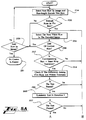
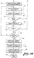
- Figures 5A and 5B show a system flowchart outlining the steps of the technique of the present invention for locating an acquisition target.
- Figure 6 shows diagrammatically a fine-tuning procedure for determining the center of a key element.
- Fig. 1 shows a prior art two-dimensional symbol 10, known as MaxiCode, which may be positioned on a label, package or the like.
- the MaxiCode symbology includes a matrix of hexagonal information encoding elements 12 arranged in a square, and, at its center, an acquisition target 100 consisting of six concentric rings of alternating light and dark reflectivity.
- FIG. 2 is a flow diagram showing the overall process of the present invention for obtaining an image of the symbol, detecting its bull's eye acquisition target, estimating the size of hexagons, determining threshold levels for distinguishing black hexagons from white hexagons, determining the orientation of symbol axes contained within the MaxiCode symbol, fine tuning values for axis direction and hexagon size, and locating the centers of individual hexagons for decoding of the information contained within the symbol.
- This overall flow diagram as the subcomponents of the process are described in detail.
- the sensing mechanism 20 includes a CCD (charge-coupled device) video camera 30, such as a Pulnix 7-CN manufactured by Pulnix America, Inc. of Sunnyvale, California 94086.
- the target is illuminated by a light source, such as one or more LEDs 22, and the reflected light from the symbol 10 on the label 14 is focused by optics 24 onto the detector of the camera 30.
- Such a camera includes a matrix of pixels which form an image by providing an output signal related to the amount of light falling on the pixel. These output signals are conventionally read out to an analog-to-digital converter 32 to generate an array of image data which may, for example, range from 0 (black) to 255 (white), and to store such data in a computer memory 34 under control of a microprocessor 36.
- an analog-to-digital converter 32 to generate an array of image data which may, for example, range from 0 (black) to 255 (white), and to store such data in a computer memory 34 under control of a microprocessor 36.
- the process of obtaining such image data in computer memory is described in U.S. Patents No. 4,874,936 and 4,896,029, which are incorporated herein by reference.
- the present invention is preferably implemented in software in C language running on a personal computer such as Compaq Deskpro 50M with an image grab card therein.
- the image grab card provides an interface between the CCD camera and the computer.
- the image grab card used in the present invention is a PowerGrabber marketed by Dipix Technologies of Canada.
- the processor 36 in the computer may be programmed by a person of ordinary skill to carry out the following operations on the image data stored in the memory 34. It should also be understood that the functions of the invention could be embodied in hardwired logic circuits or in application specific integrated circuits (ASICs).
- ASICs application specific integrated circuits
- the digitized video signal can be viewed as a two-dimensional image.
- the x axis as shown in Fig. 1 is parallel to the rows of pixels of the CCD detector of the camera, but the camera may capture the symbol 10 at any angle relative to the x axis. Also, the camera may be tilted relative to the plane of the symbol, causing some distortion of the image.
- the inner light core 102 is considered one of the three light concentric rings.
- the inner core 102 provides a key element and the other rings provide border elements, all of which can be used to locate the target in a manner described below.
- data representing the light rings have high numerical values due to the high reflectivity of the light rings and those data representing the dark rings have low numerical values due to the low reflectivity of the dark rings.
- the location of an acquisition target is not done by matching a synthetic template. Instead, the location process (represented in step 208 of Fig. 2) is carried out within the image data itself by using the symmetric property of the acquisition target.
- Fig. 4 shows the same acquisition target 100 with four axes separated by 45 degree angles.
- An axis 300 points to the East or in horizontal direction
- an axis 302 points to the North or in vertical direction
- axes 304 and 306 point to the Northeast and Northwest, respectively.
- Axis 300 is the same as the x axis shown in Fig. 1, and is defined as being parallel to the rows of pixels.
- the acquisition target is symmetric about any one of these axes.
- the symmetry is not limited to these axes in the preferred acquisition target, whose concentric circular rings are omni-directionally symmetric.
- references to direction herein, such as “North”, or “vertical”, are used only to provide a relative frame of reference.
- step 208 of Fig. 2 for locating the center of the acquisition target is shown diagrammatically in more detail with reference to corresponding processing devices. Additionally, to provide information for possible estimation of image resolution, the diameter of the target is obtained.
- a stating row number in the image is selected.
- a threshold for distinguishing white pixels from black pixels is determined from the set of values for the current row.
- the threshold is used to find transitions between black and white areas of the stored image.
- a middle value computed as 1/2(P max + P min ) is selected as the threshold, where P max and P min are the maximum and minimum pixel values in the current row.
- a threshold may be calculated in the same way for the entire image, but providing a separate threshold for each row is preferred for the process of locating the center of the acquisition target.
- a different method for determining the threshold is disclosed below in connection with determining the orientation of the symbol.
- the data can be run-length encoded.
- the corresponding run-length encoded sequence is given by: 78355454.
- the numerical value representing the number of contiguous occurrences of the same letter in the immediate group is called a "run".
- the total number of runs in the example is 8. Note that the coding is always started with the first black pixel in the scanning direction. Thus, if one indexes the coded sequence by 1, 2, 3, . . . , then the runs indexed by even numbers stand for white runs.
- the number of runs is compared with the number of rings at block 255.
- the number of runs must be greater than 13. If the number of runs is less than a predefined number (preferably 13), there is no need to further test for symmetry of the target 100 along this row. In this case the program proceeds to block 259 and tests to determine whether the current row is the last row in the image. If so, a message is generated in block 261 that no target was found in the image. If not, the program returns to block 254 to examine the next row. It will be understood that the predefined minimum number of runs is dependent upon the number of concentric rings comprising the target.
- the program examines in turn each white run in the current row. Due to the pattern of this acquisition target, the first two white runs and the last two white runs cannot be the center white run. Therefore, we can limit the search to the white runs which are respectively offset to the first and last white runs of the coded sequence by a certain number, (e.g., 2).
- the first white run is selected.
- the run is tested to determine if it is already at the end of the current row. If so, the program proceeds to block 259 for the test described above. If not, at blocks 262 and 264 the program tests to determine if the white run represents the inner ring 102.
- the size of the acquisition target can not be arbitrarily big.
- a certain maximum length e.g. 6 pixels
- the white run is longer than this tolerance, tested at block 262, then there is no need to continue testing this run for symmetry, and the program returns to block 256. If the test result shows the white run is within the tolerance, a further test at block 264 is carried out to compare the white run with the proceeding two white runs and the following two white runs. Note that if the three light rings by design have the same width, as is the case in the preferred target shown in Fig. 4, the width of their corresponding runs may differ from each other by one or at most two pixels as a result of the thresholding process or insufficient image resolution.
- One similarity test in the preferred embodiment is to see if the center white run plus one pixel is at least as long as each of its four neighboring white runs. It should be clear that this test is not sensitive to any variation in the black/white pixel threshold described above (that is, the choice of the threshold is not critical). If the center white run plus one pixel is shorter than any one of its four neighboring white runs, then it can not be the representative of the inner ring 102, and the program returns to block 256.
- this diagonal diameter along axis 304 should be closely related to the one previously computed along axis 300.
- the difference between these two diameters is directly proportional to the tilt angle which causes image distortion.
- a tolerance can be set according to the maximum tilt angle allowed in the imaging process. For example a tolerance of 4 pixels works for tilt angle up to 30 degrees. If the difference is bigger than the selected tolerance, tested at block 280, then the alleged center (x 1 , y 1 ) is discarded and the program returns to block 256 to address a new run, and eventually, if necessary, a new row of data for run-length encoding to repeat the above described tests.
- any failure will return the program to block 256.
- one failure may be permitted before abandoning the candidate run. For example, failure along one of the diagonal axes may be tolerated if the other diagonal axis and vertical axis pass the symmetry and diameter tests.
- a fine-tuning procedure at blocks 286 and 288 is executed based on the staring coordinates (x 1 , y 1 ).
- Figure 6 shows the tuning procedure diagrammatically. The coordinates (x 1 , y 1 ) are within the inner ring 102 and assumed to lie at pixel 402. Given y 1 , a tuning window is defined. The size of the window is defined by the size of the inner white ring 102.
- the lengths of at least 2 rows of data (the length of the white run) within the inner ring 102 just above and below y 1 are counted, such as row y 0 , y 2 and y 3 .
- Numerical values representing the corresponding lengths are then obtained, for example the length of row y 0 may be 5 pixels and the length of row y 2 may be 7 pixels.
- the new vertical coordinate is chosen in the longest row, that is, in the row measuring the greatest width of the inner ring 102. This establishes a new candidate center 404 (which in the example shown is at coordinates (x 1 , y 2 )).
- the same type of measurement is again performed along the columns based on the coordinates (x 1 , y 2 ), to find the longest column within the inner ring 102 (which turns out to be x 2 in the example shown in Fig. 6).
- the intersection of the longest row and the longest column, at coordinates (x 2 , y 2 ) are the final or true center coordinates of the acquisition target.
- the pixel intensity values for each of the equal rows or columns are accumulated.
- the final center coordinate in such a case is selected to be in the row or column having the largest summed intensity value.
Abstract
Description
- The present invention relates to optically encoded symbologies, and more particularly relates to decoding a two-dimensional optical symbol in spatial domain.
- Optical symbology refers to an information encoded symbol that is only readable by an optical sensing mechanism through a decoding process. For years, the bar code has been promoted as a machine-readable symbology. A bar code is a one-dimensional symbol that contains a unique serial number encoded in black and white bars. Bar codes are widely used as indices to associate physical objects with larger databases containing more detailed information.
- One example of a system for processing an image including a bar code is shown in EP-A-0 449 634, which discloses determining the fine orientation of a bar code by dividing the image area into vertical cells 52, some of which may be superimposed over a portion of a bar code label. For each scan line within the cell, a signal corresponding to the gray level of the pixels along that scan line in the cell is obtained (Fig. 8c), as well as the offset between the signals generated by different scan lines (Fig. 8d). A cross-correlation function (Fig. 9) of the first scan line of the cell with each of the successive scan lines is used to determine the orientation of the bars of the bar code relative to the scan lines.
- As the demand for information-based technologies grows, there is considerable interest in eliminating the associated database and storing more data information in the bar code itself. With current technology, encoding additional information makes a one-dimensional bar code unrealistically long. A number of two-dimensional symbologies, either in the form of a stacked bar code or a matrix type, have been introduced to accommodate this need.
- A two-dimensional symbol is composed of a two-dimensional array of elements which comprise information cells. The sire of the array, or the size of a symbol is then determined by the encoding procedures and the information to be encoded. The cells in the symbol are generally polygonal in shape and appear to be as either white or black. Thus, a symbol is comprised based on the geometric shape of the cells and the structures. All elements, either white or black, in a symbol are equal-sized and equal-shaped.
- The primary objective of using a two-dimensional symbology is to eliminate the associated database as used in bar code applications. Thus, the symbol becomes a portable information carrier that is database independent. The feature of being an information carrier is particularly important in transportation and distribution industries in which letters, packages, containers, and other related items that are shipped or transported are generally identified by the origin, flight number, destination, name, price, part number, and other information. The information is encoded into a label which is read along the distribution route. Other applications for these labels include automatic routing and sorting of mail, parcels, and baggage.
- One of the two-dimensional symbologies, publicly known as MaxiCode symbology, is disclosed in EP-A-0 573 129 and in U. S. Patents No. 4,874,936 and 4,896,029 to Chandler and et al. The disclosed symbol is an example in which the cells are hexagonal in shape and approximately 30 mils in diameter. To decode such a symbol, one has to determine the reflectance intensity on each element. To correctly determine the gray scale intensity of each hexagonal element, first the position and orientation of the symbol must be found, and the location of the center of each element identified.
- EP-A-0 573 129 also discloses an acquisition target formed of a plurality of concentric rings of contrasting reflectivities, which will yield a periodic video signal when scanned linearly. A method of finding the acquisition target uses analog filter means, the signal being compared directly with a predetermined frequency, allowing matching of the frequencies. Despite this method, there has further been a need in the art for a system of reduced computational complexity for locating two-dimensional acquisition targets, which at the same time is more efficient and more reliable. There also has been a need for such a system that can efficiently locate an acquisition target regardless of its size.
- The present invention has been made in consideration of the above described problems.
- According to an aspect of the invention, a two-dimensional acquisition target is located by finding its key element, a geometrically symmetric bonded element of a first reflectivity surrounded by a geometrically symmetric border area of a second reflectivity. Generally described, the system and method locate the key element by scanning the stored image along a first scanning direction, detecting a candidate bounded element and associated border area demonstrating symmetry along the first scanning direction, and determining whether the candidate bounded element and associated border area are symmetric along a second direction different from the first direction. The advantage of using symmetry tests is that they are invariant to distortion of the image of the acquisition target due to a tilt angle between the target and the sensing mechanism since the symmetric characteristic of the acquisition target is preserved in the distorted image. Preferably, the system and method also include determining diameters of the candidate bounded element and its associated border area in each of the directions in which they exhibit symmetry; and determining whether the diameters are within a predetermined tolerance of each other. The step of detecting symmetry along the scanning direction preferably comprises run-length coding the rows of the image, and examining the runs for symmetry.
- Therefore the present invention seeks to provide an improved system for locating an acquisition target in a digital image, such as an image of a two-dimensional symbology.
- Other objects, features and advantages of the present invention will become apparent upon examining the following description of the preferred embodiment of the invention, when taken in conjunction with the accompanying drawings and the appended claims.
- Figure 1 is a plan view of a two-dimensional symbol with indicated six axes.
- Figure 2 shows the system flowchart outlining the decoding of the symbol in spatial domain.
- Figure 3 is a system block diagram for imaging a two-dimensional acquisition target or symbol in which the processor is configured according to the present invention.
- Figure 4 shows the axes used to test the symmetric features of the acquisition target in the preferred embodiment of the invention.
- Figures 5A and 5B show a system flowchart outlining the steps of the technique of the present invention for locating an acquisition target.
- Figure 6 shows diagrammatically a fine-tuning procedure for determining the center of a key element.
- Referring now to the drawings, in which like numerals refer to like parts throughout the several views, Fig. 1 shows a prior art two-
dimensional symbol 10, known as MaxiCode, which may be positioned on a label, package or the like. The MaxiCode symbology includes a matrix of hexagonalinformation encoding elements 12 arranged in a square, and, at its center, anacquisition target 100 consisting of six concentric rings of alternating light and dark reflectivity. Fig. 2 is a flow diagram showing the overall process of the present invention for obtaining an image of the symbol, detecting its bull's eye acquisition target, estimating the size of hexagons, determining threshold levels for distinguishing black hexagons from white hexagons, determining the orientation of symbol axes contained within the MaxiCode symbol, fine tuning values for axis direction and hexagon size, and locating the centers of individual hexagons for decoding of the information contained within the symbol. Reference will be made to this overall flow diagram as the subcomponents of the process are described in detail. - Referring to Fig. 3, the components of a
sensing mechanism 20 are shown diagrammatically. The purpose of thesensing mechanism 20 is to acquire an image of indicia on a surface such as alabel 14. This mechanism carries outsteps sensing mechanism 20 includes a CCD (charge-coupled device)video camera 30, such as a Pulnix 7-CN manufactured by Pulnix America, Inc. of Sunnyvale, California 94086. The target is illuminated by a light source, such as one ormore LEDs 22, and the reflected light from thesymbol 10 on thelabel 14 is focused byoptics 24 onto the detector of thecamera 30. Such a camera includes a matrix of pixels which form an image by providing an output signal related to the amount of light falling on the pixel. These output signals are conventionally read out to an analog-to-digital converter 32 to generate an array of image data which may, for example, range from 0 (black) to 255 (white), and to store such data in acomputer memory 34 under control of amicroprocessor 36. The process of obtaining such image data in computer memory is described in U.S. Patents No. 4,874,936 and 4,896,029, which are incorporated herein by reference. - The present invention is preferably implemented in software in C language running on a personal computer such as Compaq Deskpro 50M with an image grab card therein. The image grab card provides an interface between the CCD camera and the computer. The image grab card used in the present invention is a PowerGrabber marketed by Dipix Technologies of Canada. The
processor 36 in the computer may be programmed by a person of ordinary skill to carry out the following operations on the image data stored in thememory 34. It should also be understood that the functions of the invention could be embodied in hardwired logic circuits or in application specific integrated circuits (ASICs). - To access any pixel in the
computer memory 34, two parameters, x representing column and y representing row, that is, coordinates (x, y), are used as an address to a pixel. Therefore, the digitized video signal can be viewed as a two-dimensional image. The x axis as shown in Fig. 1 is parallel to the rows of pixels of the CCD detector of the camera, but the camera may capture thesymbol 10 at any angle relative to the x axis. Also, the camera may be tilted relative to the plane of the symbol, causing some distortion of the image. - Of the six rings comprising the MaxiCode acquisition target, there are three
dark rings light rings inner light core 102 is considered one of the three light concentric rings. Theinner core 102 provides a key element and the other rings provide border elements, all of which can be used to locate the target in a manner described below. - In the stored multiple-row image of the
symbol 10, data representing the light rings have high numerical values due to the high reflectivity of the light rings and those data representing the dark rings have low numerical values due to the low reflectivity of the dark rings. - According to the present invention, the location of an acquisition target is not done by matching a synthetic template. Instead, the location process (represented in
step 208 of Fig. 2) is carried out within the image data itself by using the symmetric property of the acquisition target. Fig. 4 shows thesame acquisition target 100 with four axes separated by 45 degree angles. Anaxis 300 points to the East or in horizontal direction, anaxis 302 points to the North or in vertical direction, and axes 304 and 306 point to the Northeast and Northwest, respectively.Axis 300 is the same as the x axis shown in Fig. 1, and is defined as being parallel to the rows of pixels. In the preferred embodiment shown, the acquisition target is symmetric about any one of these axes. In fact, the symmetry is not limited to these axes in the preferred acquisition target, whose concentric circular rings are omni-directionally symmetric. Of course, references to direction herein, such as "North", or "vertical", are used only to provide a relative frame of reference. - Referring now to Figs. 5A and 5B, the process of
step 208 of Fig. 2 for locating the center of the acquisition target is shown diagrammatically in more detail with reference to corresponding processing devices. Additionally, to provide information for possible estimation of image resolution, the diameter of the target is obtained. - In block 254 a stating row number in the image is selected. Thus, a row of pixel values is being addressed. A threshold for distinguishing white pixels from black pixels is determined from the set of values for the current row. The threshold is used to find transitions between black and white areas of the stored image. There are many methods of determining the threshold known to those in the art, such as the histogram method described in U.S. Patent No. 4,874,936. Preferably, a middle value computed as 1/2(Pmax + Pmin) is selected as the threshold, where Pmax and Pmin are the maximum and minimum pixel values in the current row. Alternately, a threshold may be calculated in the same way for the entire image, but providing a separate threshold for each row is preferred for the process of locating the center of the acquisition target. A different method for determining the threshold is disclosed below in connection with determining the orientation of the symbol.
- Based on the calculated threshold, the data can be run-length encoded. The following is an example:
BBBBBBBWWWWWWWWBBBWWWWWBBBBBWWWWBBBBBWWWW
Those pixel values under the threshold are labeled by letter B (i.e., Black) and those over the threshold are labeled by letter W (i.e., White). The corresponding run-length encoded sequence is given by:
78355454.
The numerical value representing the number of contiguous occurrences of the same letter in the immediate group is called a "run". The total number of runs in the example is 8. Note that the coding is always started with the first black pixel in the scanning direction. Thus, if one indexes the coded sequence by 1, 2, 3, . . . , then the runs indexed by even numbers stand for white runs. - To detect numerically the possibility that a row passing through the center of the acquisition target has currently been encoded, the number of runs is compared with the number of rings at
block 255. Along theaxis 300 of thetarget 100, which crosses the five borderingrings center ring 102 once, there are at least 12 "W to B" or "B to W" transitions. Thus, for a row going through the centerwhite ring 102 of the giventarget 100, the number of runs must be greater than 13. If the number of runs is less than a predefined number (preferably 13), there is no need to further test for symmetry of thetarget 100 along this row. In this case the program proceeds to block 259 and tests to determine whether the current row is the last row in the image. If so, a message is generated inblock 261 that no target was found in the image. If not, the program returns to block 254 to examine the next row. It will be understood that the predefined minimum number of runs is dependent upon the number of concentric rings comprising the target. - If the number of runs is greater than the predefined number, the program examines in turn each white run in the current row. Due to the pattern of this acquisition target, the first two white runs and the last two white runs cannot be the center white run. Therefore, we can limit the search to the white runs which are respectively offset to the first and last white runs of the coded sequence by a certain number, (e.g., 2). At
block 256, the first white run is selected. Atblock 258, the run is tested to determine if it is already at the end of the current row. If so, the program proceeds to block 259 for the test described above. If not, atblocks inner ring 102. - For an image of fixed size, the size of the acquisition target can not be arbitrarily big. A certain maximum length (e.g. 6 pixels) can be imposed on the length of the inner white run in order to speed up the locating process. If the white run is longer than this tolerance, tested at
block 262, then there is no need to continue testing this run for symmetry, and the program returns to block 256. If the test result shows the white run is within the tolerance, a further test atblock 264 is carried out to compare the white run with the proceeding two white runs and the following two white runs. Note that if the three light rings by design have the same width, as is the case in the preferred target shown in Fig. 4, the width of their corresponding runs may differ from each other by one or at most two pixels as a result of the thresholding process or insufficient image resolution. - There are different ways to compare the similarity between the current white run and the neighboring white runs. One similarity test in the preferred embodiment is to see if the center white run plus one pixel is at least as long as each of its four neighboring white runs. It should be clear that this test is not sensitive to any variation in the black/white pixel threshold described above (that is, the choice of the threshold is not critical). If the center white run plus one pixel is shorter than any one of its four neighboring white runs, then it can not be the representative of the
inner ring 102, and the program returns to block 256. - If the current run satisfies the test of
block 264, atblock 268 the following symmetry test is carried out, given anacquisition target 100 formed of 6 concentric rings originally printed with roughly identical width: - (1) Let l be the length of the current white run. Let w 1, w 2, w 3, w 4 be the two preceding and two following white runs, and let b 1, b 2, b 3, b 4 be the two preceding and two following black runs, of the current row. Denote the average lengths of white runs and black runs respectively by w and b. Then ,


dark ring 105 is not used in the test, because its width may sometimes be affected by noisy components (e.g. dark symbol components - hexagons in the case of MaxiCode symbology) adjacent to it. If the foregoing first symmetry test is failed, the program returns to block 256. - After passing the symmetry test along
axis 300, at block 272 a candidate center coordinate (x1, y1) of the acquisition target is declared and the estimated diameter of the entire target along axis 300 (still excluding the outer dark ring 105) is estimated as:
- Based on the candidate center (x1, y1), further symmetry tests are carried out at
blocks 274 to 282 to verify that the coordinates (x1, y1) are within the center of the acquisition target. A new direction for symmetry testing is selected atblock 274. Starting from the pixel (x1, y1), and using the same threshold as is used in the current horizontal direction, run-length coding both downwardly and upwardly alongaxis 304 is performed until a total of five "W to B" or "B to W" transitions in each direction are obtained. This results in four white runs and four black runs centered at the candidate center white run. The foregoing symmetry test is applied to these runs atblock 276, and the diameter of the acquisition target along this axis is computed and saved atblock 278. - It will be understood by those skilled in the art that this diagonal diameter along
axis 304, the number of pixels multiplied by a factor of √2, should be closely related to the one previously computed alongaxis 300. The difference between these two diameters is directly proportional to the tilt angle which causes image distortion. A tolerance can be set according to the maximum tilt angle allowed in the imaging process. For example a tolerance of 4 pixels works for tilt angle up to 30 degrees. If the difference is bigger than the selected tolerance, tested atblock 280, then the alleged center (x1, y1) is discarded and the program returns to block 256 to address a new run, and eventually, if necessary, a new row of data for run-length encoding to repeat the above described tests. Otherwise, the program returns to block 274, and the symmetry test and diameter check will be continued alongaxes axis 302, passing through the candidate center (x1, y1), pass the symmetry test and the diameter check, the alleged center (x1, y1) is confirmed atblock 284. In the embodiment shown, any failure will return the program to block 256. However, to allow for distortion or for imperfections in the image of the acquisition target, one failure may be permitted before abandoning the candidate run. For example, failure along one of the diagonal axes may be tolerated if the other diagonal axis and vertical axis pass the symmetry and diameter tests. - It will be understood by those skilled in the art that the candidate center (x1, y1) must now lie in the
inner light ring 102, yet it may not be in the true center of the acquisition target. A fine-tuning procedure atblocks inner ring 102 and assumed to lie atpixel 402. Given y1, a tuning window is defined. The size of the window is defined by the size of the innerwhite ring 102. The lengths of at least 2 rows of data (the length of the white run) within theinner ring 102 just above and below y1 are counted, such as row y0, y2 and y3. Numerical values representing the corresponding lengths are then obtained, for example the length of row y0 may be 5 pixels and the length of row y2 may be 7 pixels. The new vertical coordinate is chosen in the longest row, that is, in the row measuring the greatest width of theinner ring 102. This establishes a new candidate center 404 (which in the example shown is at coordinates (x1, y2)). - Then, the same type of measurement is again performed along the columns based on the coordinates (x1, y2), to find the longest column within the inner ring 102 (which turns out to be x2 in the example shown in Fig. 6). The intersection of the longest row and the longest column, at coordinates (x2, y2) are the final or true center coordinates of the acquisition target.
- When there are two or more column or row length values that happen to be the same, at
block 288 of Fig. 5 the pixel intensity values for each of the equal rows or columns are accumulated. The final center coordinate in such a case is selected to be in the row or column having the largest summed intensity value. - There is a fixed size relationship between the overall MaxiCode symbology, the rings of the acquisition target, and the individual hexagons. Therefore, it will be understood that upon determining an estimate of the size of the acquisition target as described above, the average size of the individual hexagons in the image can be calculated. This may be expressed in terms of the average hexagon diameter, which is the distance between opposed flat sides of a hexagon. In the MaxiCode symbology, in which the hexagons are packed together, the hexagon diameter is equal to the distance between the centers of adjacent hexagons. Thus, references to hexagon size may be taken to refer also to hexagon spacing. This would not necessarily be true for all two-dimensional symbologies.
- The present invention has been described in relation to particular embodiments which are intended in all respects to be illustrative rather than restrictive. Alternative embodiments will become apparent to those skilled in the art to which the present invention pertains without departing from its spirit and scope. Accordingly, the scope of the present invention is defined by the appended claims rather than the foregoing description.
Claims (17)
- A method of locating an optically readable, two-dimensional acquisition target (100) in a stored image, said target being of the type having a key element (102), said key element being a geometrically symmetric, bounded element of a first reflectivity surrounded by a geometrically symmetric border area (101) of a second reflectivity, characterised by the steps of:scanning said stored image along a first scanning direction and detecting a candidate bounded element and associated border area demonstrating symmetry along said first scanning direction; anddetermining whether said candidate bounded element and associated border area are symmetric along a second direction different from the first direction.
- The method of Claim 1, further comprising the steps of:determining diameters of said candidate bounded element and said associated border area in said first scanning direction and said second direction; anddetermining whether said diameters are within a predetermined tolerance of each other.
- The method of Claim 1, wherein said step of detecting a candidate bounded element and associated border area demonstrating symmetry along said first scanning direction comprises run-length coding the rows of said image, and examining said runs for symmetry.
- The method of Claim 1, wherein said key border area comprises a plurality of symmetric rings (101-106) of alternating first and second reflectivity surrounding said key element; further comprising the steps of:finding a center point of said candidate bounded element;determining whether said candidate bounded element and associated border area are symmetric along at least one of a pair of diagonal directions passing through said center point;determining whether said candidate bounded element and associated border area are symmetric along a vertical direction normal to said first scanning direction;determining diameters of said candidate bounded element and border area in each of said directions in which they exhibit symmetry; anddetermining whether said diameters are within a predetermined tolerance of each other.
- The method of Claim 4, further comprising the steps of averaging said diameters and determining the size of said target (100) based on said average diameter.
- The method of Claim 4, wherein said steps of determining whether said candidate bounded element and said associated border area are symmetric comprise the step of determining whether the width of said bounded element (102) is at least as long as the widths of each of said border area rings (101-106) of alternating reflectivity on both sides of said bounded element.
- The method of Claim 6, wherein said steps of determining whether said candidate bounded element and said associated border area are symmetric further comprise the steps of:determining whether the absolute value of the difference between a first average width of the rings of the first reflectivity (101,103,105) on both sides of said bounded element and a second average width of the rings of the second reflectivity (104,106) on both sides of said bounded element is less than a preset tolerance;determining whether the difference between the first average width of the rings of the first reflectivity on both sides of said bounded element and the individual components of said first average is less than said preset tolerance; anddetermining whether the difference between the second average width of the rings of the second reflectivity on both sides of said bounded element and the individual components of said second average is less than said preset tolerance.
- The method of Claim 7, further comprising the steps of finding a pair of longest orthogonal dimensions (xi,yi)within said bounded element and assigning a center point of said bounded element at the intersection of said longest orthogonal dimensions.
- A system for locating an optically readable, two-dimensional acquisition target in a stored image, said target being of the type having a key element, said key element being a geometrically symmetric, bounded element of a first reflectivity surrounded by a geometrically symmetric key border area of a second reflectivity, said system including a light source (22); a detector (30) comprising an array of pixels positioned to receive light from said light source reflected by said target; a read-out circuit (32) connected to obtain data signals from said pixels and to form in a memory device (34) an image including said target; and a processor (36), characterised in that said processor is configured to locate said key element by:scanning said stored image along a first scanning direction to detect a candidate bounded element and associated border area demonstrating symmetry along said first scanning direction; anddetermining whether said candidate bounded element and associated border area are symmetric along a second direction different from said first direction.
- The system of Claim 9, wherein said key border area comprises a plurality of symmetric rings (101-106) of alternating first and second reflectivity surrounding said key element; and wherein said processor is further configured to:find a center point of said candidate bounded element;determine whether said candidate bounded element and associated border area are symmetric along at least one of a pair of diagonal directions passing through said center point;determine whether said candidate bounded element and associated border area are symmetric along a vertical direction normal to said first scanning direction;determine diameters of said candidate bounded element and border area in each of said directions in which they exhibit symmetry; anddetermine whether said diameters are within a predetermined tolerance of each other.
- The system of Claim 10, wherein said processor is further configured to average said diameters and determine the size of said target (100) based on said average diameter.
- The system of Claim 11, wherein said processor (36) is further configured to determine whether the width of said bounded element (102) is at least as long as the widths of each of said border area rings (101-106) of alternating reflectivity on both sides of said bounded element.
- The system of Claim 12, wherein said processor (36) is further configured to:determine whether the absolute value of the difference between a first average width of the rings of the first reflectivity (101,103,105) on both sides of said bounded element and a second average width of the rings of the second reflectivity (104,106) on both sides of said bounded element is less than a preset tolerance;determine whether the difference between the first average width of the rings of the first reflectivity on both sides of said bounded element and the individual components of said first average is less than said preset tolerance; anddetermine whether the difference between the second average width of the rings of the second reflectivity on both sides of said bounded element and the individual components of said second average is less than said preset tolerance.
- The system of Claim 13, wherein said processor is further configured to find a pair of longest orthogonal dimensions (xi,yi)within said bounded element and assign a center point of said bounded element at the intersection of said longest orthogonal dimensions.
- The system of Claim 9 wherein said processor is configured to scan said stored image along a scanning direction for non-character information, and to detect a candidate bounded element demonstrating symmetry along said scanning direction using said non-character information.
- The system of Claim 9, wherein said processor is further configured to:determine diameters of said candidate bounded element and said associated border area in each of said directions in which they exhibit symmetry; anddetermine whether said diameters are within a predetermined tolerance of each other.
- The system of Claim 9, wherein said processor (36) is further configured to run-length encode the rows of said image, and examine said runs for symmetry.
Applications Claiming Priority (5)
| Application Number | Priority Date | Filing Date | Title |
|---|---|---|---|
| US304667 | 1989-01-31 | ||
| US08/254,976 US5515447A (en) | 1994-06-07 | 1994-06-07 | Method and apparatus for locating an acquisition target in two-dimensional images by detecting symmetry in two different directions |
| US254976 | 1994-06-07 | ||
| US30466794A | 1994-09-09 | 1994-09-09 | |
| EP95925498A EP0764307B1 (en) | 1994-06-07 | 1995-06-01 | Method and apparatus for decoding two-dimensional symbols in the spatial domain |
Related Parent Applications (2)
| Application Number | Title | Priority Date | Filing Date |
|---|---|---|---|
| EP95925498A Division EP0764307B1 (en) | 1994-06-07 | 1995-06-01 | Method and apparatus for decoding two-dimensional symbols in the spatial domain |
| EP95925498.8 Division | 1995-12-14 |
Publications (3)
| Publication Number | Publication Date |
|---|---|
| EP0766191A2 true EP0766191A2 (en) | 1997-04-02 |
| EP0766191A3 EP0766191A3 (en) | 1999-01-07 |
| EP0766191B1 EP0766191B1 (en) | 2000-03-08 |
Family
ID=26944350
Family Applications (2)
| Application Number | Title | Priority Date | Filing Date |
|---|---|---|---|
| EP95925498A Expired - Lifetime EP0764307B1 (en) | 1994-06-07 | 1995-06-01 | Method and apparatus for decoding two-dimensional symbols in the spatial domain |
| EP96117677A Expired - Lifetime EP0766191B1 (en) | 1994-06-07 | 1995-06-01 | Method and apparatus for decoding two-dimensional symbols in the spatial domain |
Family Applications Before (1)
| Application Number | Title | Priority Date | Filing Date |
|---|---|---|---|
| EP95925498A Expired - Lifetime EP0764307B1 (en) | 1994-06-07 | 1995-06-01 | Method and apparatus for decoding two-dimensional symbols in the spatial domain |
Country Status (11)
| Country | Link |
|---|---|
| US (1) | US6094509A (en) |
| EP (2) | EP0764307B1 (en) |
| JP (1) | JP2771899B2 (en) |
| AT (2) | ATE190415T1 (en) |
| CA (1) | CA2187209C (en) |
| DE (2) | DE69504069T2 (en) |
| DK (2) | DK0766191T3 (en) |
| ES (2) | ES2144185T3 (en) |
| GR (1) | GR3033330T3 (en) |
| PT (1) | PT766191E (en) |
| WO (1) | WO1995034043A1 (en) |
Families Citing this family (53)
| Publication number | Priority date | Publication date | Assignee | Title |
|---|---|---|---|---|
| US7304670B1 (en) | 1997-03-28 | 2007-12-04 | Hand Held Products, Inc. | Method and apparatus for compensating for fixed pattern noise in an imaging system |
| US6917720B1 (en) * | 1997-07-04 | 2005-07-12 | Daimlerchrysler Ag | Reference mark, method for recognizing reference marks and method for object measuring |
| US5984078A (en) | 1997-08-04 | 1999-11-16 | United Parcel Service Of America, Inc. | Automated shuttle sorter for conveyors |
| US6561428B2 (en) | 1997-10-17 | 2003-05-13 | Hand Held Products, Inc. | Imaging device having indicia-controlled image parsing mode |
| EP0917081B1 (en) * | 1997-11-17 | 2001-10-10 | DATALOGIC S.p.A. | Maxicode locating method |
| US6637882B1 (en) | 1998-11-24 | 2003-10-28 | Welch Allyn, Inc. | Eye viewing device for retinal viewing through undilated pupil |
| US6189702B1 (en) | 1998-11-25 | 2001-02-20 | United Parcel Service Of America, Inc. | Overhead mounted sorter for conveyors |
| US6963425B1 (en) * | 2000-08-14 | 2005-11-08 | National Instruments Corporation | System and method for locating color and pattern match regions in a target image |
| US6678425B1 (en) * | 1999-12-06 | 2004-01-13 | Xerox Corporation | Method and apparatus for decoding angular orientation of lattice codes |
| DE60118051T2 (en) * | 2000-04-06 | 2006-08-31 | Seiko Epson Corp. | Method and apparatus for reading a two-dimensional bar code and data storage medium |
| US6782119B1 (en) * | 2000-06-29 | 2004-08-24 | Ernest Ross Barlett | Space planning system |
| US6601772B1 (en) * | 2000-07-14 | 2003-08-05 | Intellidot Corporation | Compact matrix code and one-touch device and method for code reading |
| US6505123B1 (en) | 2000-07-24 | 2003-01-07 | Weatherbank, Inc. | Interactive weather advisory system |
| US7111787B2 (en) | 2001-05-15 | 2006-09-26 | Hand Held Products, Inc. | Multimode image capturing and decoding optical reader |
| US6834807B2 (en) | 2001-07-13 | 2004-12-28 | Hand Held Products, Inc. | Optical reader having a color imager |
| US6655592B2 (en) * | 2001-10-10 | 2003-12-02 | Hewlett-Packard Development Company, L.P. | Graphically demodulating graphical bar codes without foreknowledge of the original unmodulated base image |
| US6878896B2 (en) | 2002-07-24 | 2005-04-12 | United Parcel Service Of America, Inc. | Synchronous semi-automatic parallel sorting |
| US7063256B2 (en) * | 2003-03-04 | 2006-06-20 | United Parcel Service Of America | Item tracking and processing systems and methods |
| US7090134B2 (en) * | 2003-03-04 | 2006-08-15 | United Parcel Service Of America, Inc. | System for projecting a handling instruction onto a moving item or parcel |
| US7637430B2 (en) | 2003-05-12 | 2009-12-29 | Hand Held Products, Inc. | Picture taking optical reader |
| US20050012968A1 (en) * | 2003-07-14 | 2005-01-20 | Dialog Semiconductor | Pixel with variable resolution during exposure |
| JP3635374B1 (en) * | 2003-11-14 | 2005-04-06 | 有限会社Sires | Digital information carrier |
| US7341456B2 (en) * | 2004-03-25 | 2008-03-11 | Mcadams John B | Braille type device, system, and method |
| US20050227217A1 (en) * | 2004-03-31 | 2005-10-13 | Wilson Andrew D | Template matching on interactive surface |
| US7593593B2 (en) | 2004-06-16 | 2009-09-22 | Microsoft Corporation | Method and system for reducing effects of undesired signals in an infrared imaging system |
| US7561717B2 (en) * | 2004-07-09 | 2009-07-14 | United Parcel Service Of America, Inc. | System and method for displaying item information |
| US20060050961A1 (en) * | 2004-08-13 | 2006-03-09 | Mohanaraj Thiyagarajah | Method and system for locating and verifying a finder pattern in a two-dimensional machine-readable symbol |
| US7293712B2 (en) | 2004-10-05 | 2007-11-13 | Hand Held Products, Inc. | System and method to automatically discriminate between a signature and a dataform |
| US20060161469A1 (en) | 2005-01-14 | 2006-07-20 | Weatherbank, Inc. | Interactive advisory system |
| US8832121B2 (en) * | 2005-02-02 | 2014-09-09 | Accuweather, Inc. | Location-based data communications system and method |
| US8430300B2 (en) * | 2005-05-26 | 2013-04-30 | Codebroker, Llc | Using validity events to control the use of coupons containing barcodes in mobile devices that display the barcodes for reading by barcode readers |
| US7561053B2 (en) * | 2005-08-10 | 2009-07-14 | Cias, Inc. | Sequenced antenna array for determining where gaming chips with embedded RFID tags are located on a blackjack, poker or other gaming table and for myriad other RFID applications |
| US7911444B2 (en) * | 2005-08-31 | 2011-03-22 | Microsoft Corporation | Input method for surface of interactive display |
| US7942340B2 (en) * | 2005-11-24 | 2011-05-17 | Canon Kabushiki Kaisha | Two-dimensional code, and method and apparatus for detecting two-dimensional code |
| US8229467B2 (en) | 2006-01-19 | 2012-07-24 | Locator IP, L.P. | Interactive advisory system |
| DE102006005202A1 (en) * | 2006-02-02 | 2007-08-09 | Hochschule Darmstadt University Of Applied Sciences | Method for decoding information |
| CN101064840B (en) * | 2006-04-26 | 2010-11-03 | 日电(中国)有限公司 | Snake-shaped matrix coder/decoder and visual sign coding and presenting system |
| US8736615B2 (en) * | 2006-04-27 | 2014-05-27 | Codebroker, Llc | Customizing barcode images for particular displays |
| US8212857B2 (en) * | 2007-01-26 | 2012-07-03 | Microsoft Corporation | Alternating light sources to reduce specular reflection |
| US8634814B2 (en) | 2007-02-23 | 2014-01-21 | Locator IP, L.P. | Interactive advisory system for prioritizing content |
| US8746581B2 (en) | 2007-06-19 | 2014-06-10 | Codebroker, Llc | Techniques for providing an electronic representation of a card |
| AU2007254627B2 (en) * | 2007-12-21 | 2010-07-08 | Canon Kabushiki Kaisha | Geometric parameter measurement of an imaging device |
| DE102009025869A1 (en) * | 2009-05-27 | 2010-12-02 | Wincor Nixdorf International Gmbh | Method and device for recognizing bar code symbols |
| US8657200B2 (en) | 2011-06-20 | 2014-02-25 | Metrologic Instruments, Inc. | Indicia reading terminal with color frame processing |
| JP5776562B2 (en) * | 2012-01-17 | 2015-09-09 | 株式会社デンソーウェーブ | Two-dimensional code reader |
| US9521291B2 (en) * | 2013-07-19 | 2016-12-13 | Digimarc Corporation | Feature-based watermark localization in digital capture systems |
| CN104819991A (en) * | 2015-05-15 | 2015-08-05 | 北京华力兴科技发展有限责任公司 | Radiation imaging method, system and device capable of changing resolution ratio |
| CN110505814A (en) | 2017-02-20 | 2019-11-26 | 3M创新有限公司 | Optical goods and the system interacted |
| US10471478B2 (en) | 2017-04-28 | 2019-11-12 | United Parcel Service Of America, Inc. | Conveyor belt assembly for identifying an asset sort location and methods of utilizing the same |
| KR20200061370A (en) | 2017-09-27 | 2020-06-02 | 쓰리엠 이노베이티브 프로퍼티즈 캄파니 | Personal protective equipment management system using optical patterns for equipment and safety monitoring |
| CN109711223A (en) * | 2018-12-28 | 2019-05-03 | 福州符号信息科技有限公司 | A kind of promotion QR code decoding rate method and apparatus |
| US11163808B2 (en) * | 2019-04-03 | 2021-11-02 | Sap Se | Hexagon clustering of spatial data |
| CN116558424B (en) * | 2023-07-10 | 2023-09-22 | 中国科学院长春光学精密机械与物理研究所 | Displacement measuring device adopting point light source reflection imaging |
Citations (3)
| Publication number | Priority date | Publication date | Assignee | Title |
|---|---|---|---|---|
| US4874936A (en) | 1988-04-08 | 1989-10-17 | United Parcel Service Of America, Inc. | Hexagonal, information encoding article, process and system |
| US4896029A (en) | 1988-04-08 | 1990-01-23 | United Parcel Service Of America, Inc. | Polygonal information encoding article, process and system |
| EP0449634A2 (en) | 1990-03-28 | 1991-10-02 | Omniplanar, Inc. | Omnidirectional bar code reader |
Family Cites Families (38)
| Publication number | Priority date | Publication date | Assignee | Title |
|---|---|---|---|---|
| US3632995A (en) * | 1968-05-09 | 1972-01-04 | Howard W Wilson | Coded article |
| US3715724A (en) * | 1969-12-24 | 1973-02-06 | Olivetti & Co Spa | Apparatus for recognizing graphic symbols |
| US3801775A (en) * | 1972-08-07 | 1974-04-02 | Scanner | Method and apparatus for identifying objects |
| US3885229A (en) * | 1972-10-28 | 1975-05-20 | Nippon Electric Co | Document scanning apparatus |
| JPS5295121A (en) * | 1976-02-06 | 1977-08-10 | Hitachi Ltd | Code plate |
| US4695991A (en) * | 1980-12-09 | 1987-09-22 | Storage Research Pty. Ltd. | Reading information stored in multiple frame format |
| DE3373734D1 (en) * | 1982-01-20 | 1987-10-22 | Nippon Denso Co | High-sensitive optical reading apparatus and method of reading optical information |
| IT1178924B (en) * | 1984-04-20 | 1987-09-16 | Elsag | PROCEDURE AND EQUIPMENT TO CARRY OUT A SEARCH OF PREFIXED SHAPES ON AN IMAGE |
| EP0188548A1 (en) * | 1984-07-09 | 1986-07-30 | SIERACKI, Leonard, M. | METHOD AND APPARATUS FOR SUPPLYING GAS MIXTURES TO AN $i(IN VIVO) RESPIRATORY SYSTEM |
| JPS61276080A (en) * | 1985-05-31 | 1986-12-06 | Toshiba Corp | Top and reverse surface deciding device |
| NL8501460A (en) * | 1985-05-22 | 1986-12-16 | Philips Nv | METHOD FOR IDENTIFYING OBJECTS INCLUDING A CODE FIELD WITH DOT CODE, DEVICE FOR IDENTIFYING SUCH A DOT CODE, AND PRODUCT USING SUCH A DOT CODE |
| US4776464A (en) * | 1985-06-17 | 1988-10-11 | Bae Automated Systems, Inc. | Automated article handling system and process |
| JPS6282486A (en) * | 1985-10-08 | 1987-04-15 | Hitachi Ltd | Recognizing device for online handwritten graphic form |
| US4955062A (en) * | 1986-12-10 | 1990-09-04 | Canon Kabushiki Kaisha | Pattern detecting method and apparatus |
| US5059774A (en) * | 1987-10-15 | 1991-10-22 | Ricoh Company, Ltd. | Seek and track control for a rectangular optical card handling apparatus |
| JPH01137385A (en) * | 1987-11-25 | 1989-05-30 | Matsushita Electric Ind Co Ltd | Character recognizing device |
| US4924078A (en) * | 1987-11-25 | 1990-05-08 | Sant Anselmo Carl | Identification symbol, system and method |
| US5053609A (en) * | 1988-05-05 | 1991-10-01 | International Data Matrix, Inc. | Dynamically variable machine readable binary code and method for reading and producing thereof |
| US4939354A (en) * | 1988-05-05 | 1990-07-03 | Datacode International, Inc. | Dynamically variable machine readable binary code and method for reading and producing thereof |
| US5126542A (en) * | 1988-05-05 | 1992-06-30 | International Data Matrix, Inc. | Dynamically variable machine readable binary code and method for reading and producing thereof |
| US5124536A (en) * | 1988-05-05 | 1992-06-23 | International Data Matrix, Inc. | Dynamically variable machine readable binary code and method for reading and producing thereof |
| US5229591A (en) * | 1988-10-21 | 1993-07-20 | Symbol Technologies, Inc. | Scanning system with adjustable light output and/or scanning angle |
| US5068909A (en) * | 1989-05-18 | 1991-11-26 | Applied Imaging Corporation | Method and apparatus for generating quantifiable video displays |
| US5153928A (en) * | 1989-06-09 | 1992-10-06 | Casio Computer Co., Ltd. | Method and apparatus for recording/reproducing mesh pattern data |
| FR2657982B1 (en) * | 1990-02-02 | 1992-11-27 | Cga Hbs | METHOD FOR LOCATING AN ADDRESS ON SORTING ARTICLES, ADDRESSING LABEL AND DEVICE FOR IMPLEMENTING THE METHOD. |
| US5155343A (en) * | 1990-03-28 | 1992-10-13 | Chandler Donald G | Omnidirectional bar code reader with method and apparatus for detecting and scanning a bar code symbol |
| US5241166A (en) * | 1990-07-02 | 1993-08-31 | Chandler Donald G | Low resolution target acquisition |
| US5189292A (en) * | 1990-10-30 | 1993-02-23 | Omniplanar, Inc. | Finder pattern for optically encoded machine readable symbols |
| JP3526880B2 (en) * | 1990-10-30 | 2004-05-17 | オムニプラナー,インコーポレーテッド | Multi-resolution machine readable symbol |
| US5153418A (en) * | 1990-10-30 | 1992-10-06 | Omniplanar, Inc. | Multiple resolution machine readable symbols |
| DE4035396A1 (en) * | 1990-11-07 | 1992-05-14 | F & O Elektronic Systems Gmbh | METHOD AND DEVICE FOR READING AND IDENTIFYING THE INFORMATION OF A CHARACTER TEMPLATE, IN PARTICULAR BARCODE, WITHIN A TWO OR THREE-DIMENSIONAL FIELD BY MEANS OF A VIDEO CAMERA THAT GENERATES A BINARY VIDEO SIGNAL OF THE IMAGE |
| JPH04268989A (en) * | 1991-02-25 | 1992-09-24 | Nippon Steel Corp | Method and device for recognizing character |
| KR100225151B1 (en) * | 1991-07-11 | 1999-10-15 | 엠.피.젠킨스 | System and method for acquiring an optical target |
| US5276315A (en) * | 1992-05-14 | 1994-01-04 | United Parcel Service Of America, Inc. | Method and apparatus for processing low resolution images of degraded bar code symbols |
| US5327171A (en) * | 1992-05-26 | 1994-07-05 | United Parcel Service Of America, Inc. | Camera system optics |
| US5329105A (en) * | 1992-08-10 | 1994-07-12 | United Parcel Service Of America, Inc. | Method and apparatus for determining the width of elements of bar code symbols |
| JPH09503708A (en) * | 1993-09-24 | 1997-04-15 | ヴァヴィン、ベスローテム、ヴェンノットシャップ | Quality Assurance of Electrically Weldable Joints |
| US5495537A (en) * | 1994-06-01 | 1996-02-27 | Cognex Corporation | Methods and apparatus for machine vision template matching of images predominantly having generally diagonal and elongate features |
-
1995
- 1995-06-01 PT PT96117677T patent/PT766191E/en unknown
- 1995-06-01 DE DE69504069T patent/DE69504069T2/en not_active Expired - Lifetime
- 1995-06-01 WO PCT/US1995/008432 patent/WO1995034043A1/en active IP Right Grant
- 1995-06-01 ES ES96117677T patent/ES2144185T3/en not_active Expired - Lifetime
- 1995-06-01 DE DE69515481T patent/DE69515481T2/en not_active Expired - Lifetime
- 1995-06-01 AT AT96117677T patent/ATE190415T1/en active
- 1995-06-01 JP JP8501354A patent/JP2771899B2/en not_active Expired - Fee Related
- 1995-06-01 ES ES95925498T patent/ES2122656T3/en not_active Expired - Lifetime
- 1995-06-01 EP EP95925498A patent/EP0764307B1/en not_active Expired - Lifetime
- 1995-06-01 AT AT95925498T patent/ATE169754T1/en active
- 1995-06-01 DK DK96117677T patent/DK0766191T3/en active
- 1995-06-01 DK DK95925498T patent/DK0764307T3/en active
- 1995-06-01 EP EP96117677A patent/EP0766191B1/en not_active Expired - Lifetime
- 1995-06-01 CA CA002187209A patent/CA2187209C/en not_active Expired - Fee Related
-
1997
- 1997-08-12 US US08/909,574 patent/US6094509A/en not_active Expired - Lifetime
-
2000
- 2000-04-26 GR GR20000401014T patent/GR3033330T3/en not_active IP Right Cessation
Patent Citations (4)
| Publication number | Priority date | Publication date | Assignee | Title |
|---|---|---|---|---|
| US4874936A (en) | 1988-04-08 | 1989-10-17 | United Parcel Service Of America, Inc. | Hexagonal, information encoding article, process and system |
| US4896029A (en) | 1988-04-08 | 1990-01-23 | United Parcel Service Of America, Inc. | Polygonal information encoding article, process and system |
| EP0573129A2 (en) | 1988-04-08 | 1993-12-08 | United Parcel Service Of America, Inc. | Polygonal information encoding article, process and system |
| EP0449634A2 (en) | 1990-03-28 | 1991-10-02 | Omniplanar, Inc. | Omnidirectional bar code reader |
Also Published As
| Publication number | Publication date |
|---|---|
| EP0764307A1 (en) | 1997-03-26 |
| US6094509A (en) | 2000-07-25 |
| ES2122656T3 (en) | 1998-12-16 |
| EP0766191B1 (en) | 2000-03-08 |
| CA2187209C (en) | 2000-09-05 |
| DE69504069T2 (en) | 1998-12-10 |
| PT766191E (en) | 2000-08-31 |
| EP0764307B1 (en) | 1998-08-12 |
| DE69504069D1 (en) | 1998-09-17 |
| DK0766191T3 (en) | 2000-07-31 |
| DK0764307T3 (en) | 1999-05-10 |
| ATE190415T1 (en) | 2000-03-15 |
| CA2187209A1 (en) | 1995-12-14 |
| WO1995034043A1 (en) | 1995-12-14 |
| JPH10501082A (en) | 1998-01-27 |
| DE69515481D1 (en) | 2000-04-13 |
| ATE169754T1 (en) | 1998-08-15 |
| EP0766191A3 (en) | 1999-01-07 |
| JP2771899B2 (en) | 1998-07-02 |
| ES2144185T3 (en) | 2000-06-01 |
| GR3033330T3 (en) | 2000-09-29 |
| DE69515481T2 (en) | 2000-10-19 |
Similar Documents
| Publication | Publication Date | Title |
|---|---|---|
| EP0766191B1 (en) | Method and apparatus for decoding two-dimensional symbols in the spatial domain | |
| US5515447A (en) | Method and apparatus for locating an acquisition target in two-dimensional images by detecting symmetry in two different directions | |
| EP0484132B1 (en) | Multiple resolution machine readable symbols | |
| US5153418A (en) | Multiple resolution machine readable symbols | |
| US6386454B2 (en) | Detecting bar code candidates | |
| US6708884B1 (en) | Method and apparatus for rapid and precision detection of omnidirectional postnet barcode location | |
| EP0336769B1 (en) | Hexagonal information encoding article, process and system | |
| EP0669593B1 (en) | Two-dimensional code recognition method | |
| KR970006647B1 (en) | Hexagonal information encoding article, process and system thereof | |
| US6088482A (en) | Techniques for reading two dimensional code, including maxicode | |
| US4998010A (en) | Polygonal information encoding article, process and system | |
| EP1138013B1 (en) | Skew processing of raster scan images | |
| US6173893B1 (en) | Fast finding algorithm for two-dimensional symbologies | |
| US7050631B2 (en) | Barcode detection system | |
| US6941026B1 (en) | Method and apparatus using intensity gradients for visual identification of 2D matrix symbols | |
| US7311262B2 (en) | Method of decoding a symbol with a low contrast | |
| US6219434B1 (en) | Maxicode locating method |
Legal Events
| Date | Code | Title | Description |
|---|---|---|---|
| PUAI | Public reference made under article 153(3) epc to a published international application that has entered the european phase |
Free format text: ORIGINAL CODE: 0009012 |
|
| 17P | Request for examination filed |
Effective date: 19961125 |
|
| AC | Divisional application: reference to earlier application |
Ref document number: 764307 Country of ref document: EP |
|
| AK | Designated contracting states |
Kind code of ref document: A2 Designated state(s): AT BE CH DE DK ES FR GB GR IE IT LI LU MC NL PT SE |
|
| RIN1 | Information on inventor provided before grant (corrected) |
Inventor name: LEI, MING Inventor name: ZHENG, JOE |
|
| PUAL | Search report despatched |
Free format text: ORIGINAL CODE: 0009013 |
|
| AK | Designated contracting states |
Kind code of ref document: A3 Designated state(s): AT BE CH DE DK ES FR GB GR IE IT LI LU MC NL PT SE |
|
| GRAG | Despatch of communication of intention to grant |
Free format text: ORIGINAL CODE: EPIDOS AGRA |
|
| 17Q | First examination report despatched |
Effective date: 19990503 |
|
| GRAG | Despatch of communication of intention to grant |
Free format text: ORIGINAL CODE: EPIDOS AGRA |
|
| GRAH | Despatch of communication of intention to grant a patent |
Free format text: ORIGINAL CODE: EPIDOS IGRA |
|
| GRAH | Despatch of communication of intention to grant a patent |
Free format text: ORIGINAL CODE: EPIDOS IGRA |
|
| GRAA | (expected) grant |
Free format text: ORIGINAL CODE: 0009210 |
|
| AC | Divisional application: reference to earlier application |
Ref document number: 764307 Country of ref document: EP |
|
| AK | Designated contracting states |
Kind code of ref document: B1 Designated state(s): AT BE CH DE DK ES FR GB GR IE IT LI LU MC NL PT SE |
|
| REF | Corresponds to: |
Ref document number: 190415 Country of ref document: AT Date of ref document: 20000315 Kind code of ref document: T |
|
| REG | Reference to a national code |
Ref country code: CH Ref legal event code: EP |
|
| REF | Corresponds to: |
Ref document number: 69515481 Country of ref document: DE Date of ref document: 20000413 |
|
| REG | Reference to a national code |
Ref country code: IE Ref legal event code: FG4D |
|
| ET | Fr: translation filed | ||
| REG | Reference to a national code |
Ref country code: CH Ref legal event code: NV Representative=s name: BOVARD AG PATENTANWAELTE |
|
| REG | Reference to a national code |
Ref country code: ES Ref legal event code: FG2A Ref document number: 2144185 Country of ref document: ES Kind code of ref document: T3 |
|
| ITF | It: translation for a ep patent filed |
Owner name: DRAGOTTI & ASSOCIATI S.R.L. |
|
| REG | Reference to a national code |
Ref country code: DK Ref legal event code: T3 |
|
| REG | Reference to a national code |
Ref country code: PT Ref legal event code: SC4A Free format text: AVAILABILITY OF NATIONAL TRANSLATION Effective date: 20000606 |
|
| PLBE | No opposition filed within time limit |
Free format text: ORIGINAL CODE: 0009261 |
|
| STAA | Information on the status of an ep patent application or granted ep patent |
Free format text: STATUS: NO OPPOSITION FILED WITHIN TIME LIMIT |
|
| 26N | No opposition filed | ||
| REG | Reference to a national code |
Ref country code: GB Ref legal event code: IF02 |
|
| PGFP | Annual fee paid to national office [announced via postgrant information from national office to epo] |
Ref country code: MC Payment date: 20050628 Year of fee payment: 11 Ref country code: GR Payment date: 20050628 Year of fee payment: 11 |
|
| PGFP | Annual fee paid to national office [announced via postgrant information from national office to epo] |
Ref country code: PT Payment date: 20050629 Year of fee payment: 11 |
|
| PGFP | Annual fee paid to national office [announced via postgrant information from national office to epo] |
Ref country code: LU Payment date: 20050705 Year of fee payment: 11 |
|
| PG25 | Lapsed in a contracting state [announced via postgrant information from national office to epo] |
Ref country code: MC Free format text: LAPSE BECAUSE OF NON-PAYMENT OF DUE FEES Effective date: 20060630 |
|
| PG25 | Lapsed in a contracting state [announced via postgrant information from national office to epo] |
Ref country code: PT Free format text: LAPSE BECAUSE OF NON-PAYMENT OF DUE FEES Effective date: 20061204 |
|
| REG | Reference to a national code |
Ref country code: PT Ref legal event code: MM4A Free format text: LAPSE DUE TO NON-PAYMENT OF FEES Effective date: 20061204 |
|
| PGFP | Annual fee paid to national office [announced via postgrant information from national office to epo] |
Ref country code: NL Payment date: 20070603 Year of fee payment: 13 |
|
| PGFP | Annual fee paid to national office [announced via postgrant information from national office to epo] |
Ref country code: SE Payment date: 20070607 Year of fee payment: 13 |
|
| PGFP | Annual fee paid to national office [announced via postgrant information from national office to epo] |
Ref country code: IE Payment date: 20070614 Year of fee payment: 13 Ref country code: CH Payment date: 20070614 Year of fee payment: 13 |
|
| PG25 | Lapsed in a contracting state [announced via postgrant information from national office to epo] |
Ref country code: LU Free format text: LAPSE BECAUSE OF NON-PAYMENT OF DUE FEES Effective date: 20060601 |
|
| PG25 | Lapsed in a contracting state [announced via postgrant information from national office to epo] |
Ref country code: GR Free format text: LAPSE BECAUSE OF NON-PAYMENT OF DUE FEES Effective date: 20070104 |
|
| REG | Reference to a national code |
Ref country code: CH Ref legal event code: PL |
|
| EUG | Se: european patent has lapsed | ||
| NLV4 | Nl: lapsed or anulled due to non-payment of the annual fee |
Effective date: 20090101 |
|
| REG | Reference to a national code |
Ref country code: IE Ref legal event code: MM4A |
|
| PG25 | Lapsed in a contracting state [announced via postgrant information from national office to epo] |
Ref country code: IE Free format text: LAPSE BECAUSE OF NON-PAYMENT OF DUE FEES Effective date: 20080602 |
|
| PG25 | Lapsed in a contracting state [announced via postgrant information from national office to epo] |
Ref country code: NL Free format text: LAPSE BECAUSE OF NON-PAYMENT OF DUE FEES Effective date: 20090101 |
|
| PG25 | Lapsed in a contracting state [announced via postgrant information from national office to epo] |
Ref country code: LI Free format text: LAPSE BECAUSE OF NON-PAYMENT OF DUE FEES Effective date: 20080630 Ref country code: CH Free format text: LAPSE BECAUSE OF NON-PAYMENT OF DUE FEES Effective date: 20080630 |
|
| PG25 | Lapsed in a contracting state [announced via postgrant information from national office to epo] |
Ref country code: SE Free format text: LAPSE BECAUSE OF NON-PAYMENT OF DUE FEES Effective date: 20080602 |
|
| PG25 | Lapsed in a contracting state [announced via postgrant information from national office to epo] |
Ref country code: IT Free format text: LAPSE BECAUSE OF NON-PAYMENT OF DUE FEES Effective date: 20090601 |
|
| PGRI | Patent reinstated in contracting state [announced from national office to epo] |
Ref country code: IT Effective date: 20110616 |
|
| PGFP | Annual fee paid to national office [announced via postgrant information from national office to epo] |
Ref country code: ES Payment date: 20120726 Year of fee payment: 18 |
|
| PGFP | Annual fee paid to national office [announced via postgrant information from national office to epo] |
Ref country code: AT Payment date: 20120529 Year of fee payment: 18 |
|
| PGFP | Annual fee paid to national office [announced via postgrant information from national office to epo] |
Ref country code: DK Payment date: 20130611 Year of fee payment: 19 Ref country code: DE Payment date: 20130605 Year of fee payment: 19 Ref country code: GB Payment date: 20130605 Year of fee payment: 19 |
|
| PGFP | Annual fee paid to national office [announced via postgrant information from national office to epo] |
Ref country code: FR Payment date: 20130624 Year of fee payment: 19 Ref country code: IT Payment date: 20130620 Year of fee payment: 19 |
|
| PGFP | Annual fee paid to national office [announced via postgrant information from national office to epo] |
Ref country code: BE Payment date: 20130614 Year of fee payment: 19 |
|
| REG | Reference to a national code |
Ref country code: DE Ref legal event code: R119 Ref document number: 69515481 Country of ref document: DE |
|
| REG | Reference to a national code |
Ref country code: DK Ref legal event code: EBP Effective date: 20140630 |
|
| REG | Reference to a national code |
Ref country code: AT Ref legal event code: MM01 Ref document number: 190415 Country of ref document: AT Kind code of ref document: T Effective date: 20140601 |
|
| GBPC | Gb: european patent ceased through non-payment of renewal fee |
Effective date: 20140601 |
|
| REG | Reference to a national code |
Ref country code: FR Ref legal event code: ST Effective date: 20150227 |
|
| REG | Reference to a national code |
Ref country code: DE Ref legal event code: R119 Ref document number: 69515481 Country of ref document: DE Effective date: 20150101 |
|
| PG25 | Lapsed in a contracting state [announced via postgrant information from national office to epo] |
Ref country code: DE Free format text: LAPSE BECAUSE OF NON-PAYMENT OF DUE FEES Effective date: 20150101 Ref country code: IT Free format text: LAPSE BECAUSE OF NON-PAYMENT OF DUE FEES Effective date: 20140601 |
|
| PG25 | Lapsed in a contracting state [announced via postgrant information from national office to epo] |
Ref country code: AT Free format text: LAPSE BECAUSE OF NON-PAYMENT OF DUE FEES Effective date: 20140601 Ref country code: FR Free format text: LAPSE BECAUSE OF NON-PAYMENT OF DUE FEES Effective date: 20140630 Ref country code: GB Free format text: LAPSE BECAUSE OF NON-PAYMENT OF DUE FEES Effective date: 20140601 |
|
| REG | Reference to a national code |
Ref country code: ES Ref legal event code: FD2A Effective date: 20150724 |
|
| PG25 | Lapsed in a contracting state [announced via postgrant information from national office to epo] |
Ref country code: DK Free format text: LAPSE BECAUSE OF NON-PAYMENT OF DUE FEES Effective date: 20140630 |
|
| PG25 | Lapsed in a contracting state [announced via postgrant information from national office to epo] |
Ref country code: ES Free format text: LAPSE BECAUSE OF NON-PAYMENT OF DUE FEES Effective date: 20140602 |
|
| PG25 | Lapsed in a contracting state [announced via postgrant information from national office to epo] |
Ref country code: BE Free format text: LAPSE BECAUSE OF NON-PAYMENT OF DUE FEES Effective date: 20140630 |