EP0767945B1 - Wireless communication system for reliable communication between a group of apparatuses - Google Patents
Wireless communication system for reliable communication between a group of apparatuses Download PDFInfo
- Publication number
- EP0767945B1 EP0767945B1 EP96907614A EP96907614A EP0767945B1 EP 0767945 B1 EP0767945 B1 EP 0767945B1 EP 96907614 A EP96907614 A EP 96907614A EP 96907614 A EP96907614 A EP 96907614A EP 0767945 B1 EP0767945 B1 EP 0767945B1
- Authority
- EP
- European Patent Office
- Prior art keywords
- message
- frame
- series
- receiving
- frames
- Prior art date
- Legal status (The legal status is an assumption and is not a legal conclusion. Google has not performed a legal analysis and makes no representation as to the accuracy of the status listed.)
- Expired - Lifetime
Links
Images


Classifications
-
- G—PHYSICS
- G08—SIGNALLING
- G08C—TRANSMISSION SYSTEMS FOR MEASURED VALUES, CONTROL OR SIMILAR SIGNALS
- G08C19/00—Electric signal transmission systems
- G08C19/16—Electric signal transmission systems in which transmission is by pulses
- G08C19/28—Electric signal transmission systems in which transmission is by pulses using pulse code
-
- G—PHYSICS
- G08—SIGNALLING
- G08C—TRANSMISSION SYSTEMS FOR MEASURED VALUES, CONTROL OR SIMILAR SIGNALS
- G08C25/00—Arrangements for preventing or correcting errors; Monitoring arrangements
- G08C25/02—Arrangements for preventing or correcting errors; Monitoring arrangements by signalling back receiving station to transmitting station
-
- H—ELECTRICITY
- H04—ELECTRIC COMMUNICATION TECHNIQUE
- H04L—TRANSMISSION OF DIGITAL INFORMATION, e.g. TELEGRAPHIC COMMUNICATION
- H04L1/00—Arrangements for detecting or preventing errors in the information received
- H04L1/12—Arrangements for detecting or preventing errors in the information received by using return channel
- H04L1/16—Arrangements for detecting or preventing errors in the information received by using return channel in which the return channel carries supervisory signals, e.g. repetition request signals
- H04L1/18—Automatic repetition systems, e.g. Van Duuren systems
- H04L1/1829—Arrangements specially adapted for the receiver end
- H04L1/1848—Time-out mechanisms
-
- H—ELECTRICITY
- H04—ELECTRIC COMMUNICATION TECHNIQUE
- H04L—TRANSMISSION OF DIGITAL INFORMATION, e.g. TELEGRAPHIC COMMUNICATION
- H04L1/00—Arrangements for detecting or preventing errors in the information received
- H04L1/12—Arrangements for detecting or preventing errors in the information received by using return channel
- H04L1/16—Arrangements for detecting or preventing errors in the information received by using return channel in which the return channel carries supervisory signals, e.g. repetition request signals
- H04L1/18—Automatic repetition systems, e.g. Van Duuren systems
- H04L1/1829—Arrangements specially adapted for the receiver end
- H04L1/1854—Scheduling and prioritising arrangements
-
- H—ELECTRICITY
- H04—ELECTRIC COMMUNICATION TECHNIQUE
- H04L—TRANSMISSION OF DIGITAL INFORMATION, e.g. TELEGRAPHIC COMMUNICATION
- H04L1/00—Arrangements for detecting or preventing errors in the information received
- H04L1/12—Arrangements for detecting or preventing errors in the information received by using return channel
- H04L1/16—Arrangements for detecting or preventing errors in the information received by using return channel in which the return channel carries supervisory signals, e.g. repetition request signals
- H04L1/18—Automatic repetition systems, e.g. Van Duuren systems
- H04L1/1867—Arrangements specially adapted for the transmitter end
- H04L1/188—Time-out mechanisms
Definitions
- the invention relates to a wireless communication system comprising a sending apparatus and a receiving apparatus; said sending apparatus comprising message sending means for transmitting a message frame, and acknowledge receiving means for receiving an acknowledgement frame; and said receiving apparatus comprising message receiving means for receiving a message frame, and acknowledge sending means for transmitting an acknowledgement frame upon said message receiving means correctly receiving a message frame,
- the invention further relates to an apparatus suitable for use in such a system.
- Wireless communication is widely used for communication involving portable apparatuses.
- infrared light is commonly used as a carrier for wireless communication.
- a sending apparatus such as a hand-held remote control
- a receiving apparatus such as a television
- the information is transmitted in the form of message frames.
- the message frames are limited to a maximum size, allowing the transmitting and receiving apparatus to use buffers with a corresponding maximum size for temporarily storing the message frames.
- the protocols are executed by the main CPU, requiring no dedicated logic or communication ICs in addition to an infrared transmitter or an infrared receiver.
- a transmission via infrared can easily be disrupted, for instance, by other infrared transmitters operating at the same frequency.
- the communication protocols have been enhanced by using acknowledgement mechanisms to report correct reception of a transmitted frame. If no acknowledgement frame is received in response to transmitting a message frame, the message frame may be retransmitted. This may, for instance, take place on the initiative of the user, by pressing the same key on the remote control again. Also the sending apparatus may automatically retransmit the message frame, up to a predetermined maximum or until an acknowledgement frame has been received.
- the acknowledgement mechanism can also be used to detect that no communication was possible, for instance, in situations where the maximum operating distance is exceeded or optical contact is broken.
- both apparatuses comprise an infrared transmitter and an infrared receiver. Such a system is known from DE-A-3508562.
- This system describes the communication between two apparatuses, with the sending apparatus generating message frames and receiving acknowledgement frames; and the receiving apparatus receiving message frames and generating acknowledgement frames in response.
- the addition of a third apparatus may cause the system to fail.
- a message frame transmitted by the remote control comprises the address of a specific receiving apparatus. Only the addressed apparatus will receive the message frame and acknowledge it.
- apparatuses come with a factory-set address or offer the user a choice of addresses, such as a choice between the logical addresses 'VCR1' and 'VCR2' for a VCR.
- the system can fail if two remote control are present to control the same television. Nearly simultaneous use of the two remote controls will result in two message frames interfering. Automatic repetition of the transmission can result in repeated interference, particularly if the repetition rates are similar. If the second remote control transmits a second message frame shortly after the first remote control has transmitted a first message frame, the second message frame may interfere with the acknowledgement frame for the first message frame. If the second message frame is transmitted before the first message frame is acknowledged, confusion may arise to which message frame is actually acknowledged by the acknowledgement frame.
- US 4,941,143 further discloses a network for sensing, communicating and controlling, having a plurality of cells which communicate with packets.
- a transmitting cell transmits a packet requesting acknowledgements to a plurality of destination cells.
- the transmitting cell then listens for acknowledgements from the destination cells.
- the transmitting cell waits a predetermined period of time to receive the acknowledgements and then infers that a collision has occurred if a reply is not received from any of the destination cells.
- Different actions are taken by the transmitting cell as a result of the inference of a collision as opposed to a case where the cell receives an acknowledgement from at least one destination cell.
- the system comprises at least three apparatuses; each apparatus being a sending apparatus as well as a receiving apparatus, each apparatus further comprising:
- the invention uses the following mechanisms:
- a first embodiment of a system according to the invention is characterised in that said first timing means is adapted to set said first timer at a random time within a time window; said time window being chosen from a plurality of pre-determined, non-overlapping time windows, with the time window, which most closely follows said detection of the ending of a transmission of a frame, being reserved for transmitting a message frame with highest priority and each successive time window being reserved for transmitting a message frame with a successively lower priority.
- the situation can occur that a transmission of a frame delays at least two apparatuses to nearly the same moment in time (governed by the first timer). In such a situation those apparatuses could start transmitting without detecting that another transmission has simultaneously started.
- the first timer is set at a random time within a pre-determined time window. Additionally, the random time window is divided in at least two, non-overlapping time windows, making it possible to prioritise the transmission of message frames. High priority message frames use the first time window; low priority message frames use a later time window.
- the sending apparatus may further comprise third timing means for setting a third timer at a predetermined third time after the message sending means has transmitted a message frame; the message sending means being adapted to retransmit the message frame up to a predetermined maximum number of times if the third timer expires prior to the acknowledge receiving means receiving an acknowledgement frame.
- each apparatus comprises said third timing means; in that said message sending means is adapted to divide a long message over a series of message frames and to sequentially transmit said series of message frames; each successive message frame of the series being different from the immediately preceding message frame and a successive message frame being transmitted after an acknowledgement frame for the immediately preceding message frame has been received by said acknowledge receiving means; in that said message receiving means is adapted to receive a series of message frames and to distinguish between successive message frames of the series; and in that said acknowledge sending means is adapted to transmit said acknowledgement frame, upon said message receiving means correctly receiving a message frame of said series, only if said message receiving means has correctly received all preceding message frames of said series.
- long messages are divided over a series of message frames.
- the message frames are transmitted in sequence.
- the next message frame of the series is only transmitted after the current message frame has been acknowledged. If no acknowledgement is received, the current message frame is automatically retransmitted.
- the situation may also occur that a receiving apparatus has acknowledged a message frame, but that the acknowledgement frame was not correctly received by the apparatus which transmitted the message frame. In such a situation, the transmitting apparatus will retransmit the message frame.
- each successive message frame of the series is different from the immediately preceding message frame.
- a message frame is acknowledged by no more than one apparatus. The situation could occur that each individual message frame of the series is acknowledged, but that no apparatus has correctly received the entire message. For instance, of a long message, which is divided over two message frames, the first message frame might be received by apparatus A only and acknowledged by apparatus A and the second message frame might be received by apparatus B only and acknowledged by apparatus B.
- an apparatus only acknowledges correct receipt of a message frame if it has correctly received all preceding message frames of the series.
- the system is characterised in that the acknowledge sending means is adapted to transmit the acknowledgement frame only if the acknowledge sending means has transmitted an acknowledgement frame for all preceding message frames of said series.
- the apparatus which acknowledged the first message frame of the series, is the only apparatus which acknowledges the remaining message frames of the series.
- the system is characterised in that a message frame, which is the first of a series of message frames, is assigned a lower priority than the remaining message frames of the series. This ensures that, once the transmission of a long message has started, the long message has gained priority. Otherwise it is possible that, particularly in systems in which a large number of messages are transmitted, every individual message frame of the series would have to compete with all messages to be transmitted by the other apparatuses. This could potentially make the duration of the transmission very long.
- the described system is, therefore, particulary advantageous for infrared based systems in which the chance of loosing optical contact increases if the transmission takes a long time.
- the system is characterised in that message frames of a series of message frames comprise a number which is different for successive message frames of the series. Using numbers is a simple way of distinguishing between successive frames. For example, numbers can be used which are sequentially higher for successive message frames of the series.
- the system is characterised in that successive message frames of the series alternatingly comprise the number zero or one. Using this mechanism, only one bit location in the message frame needs to be reserved for this number, which allows the receiving apparatus to simply differentiate between a retransmission and a transmission of the next message frame of the series.
- each apparatus comprises checksum calculation means for calculating a checksum representing a series of message frames; said message sending means is adapted to cause said checksum calculation means to calculate a first checksum representing the series of message frames to be transmitted by said message sending means; said message sending means inserting said first checksum in a predetermined message frame of the series; said message sending means is further adapted to insert in the last message frame of the series an indication that this message frame is the last message frame of the series; said message receiving means is adapted to cause said checksum calculation means to calculate a second checksum representing the series of message frames received by said message receiving means; said acknowledge sending means is adapted to, upon said message receiving means receiving the last message frame of the series, transmit said acknowledgement frame only if said first checksum comprised in said predetermined message frame of the series received by said message receiving means matches said second checksum.
- the checksum allows the receiving apparatuses to determine whether all message frames of the series have been received correctly. If a receiving apparatus detects an error, it does not acknowledge the last message frame of the series. In this manner, the sending apparatus can detect that not only individual message frames have been correctly received but that the entire message has been received.
- An additional advantage occurs when using infrared based communication, particularly for portable apparatuses. In such systems optical contact can easily be broken. Without precautions this could result in the following scenario: an apparatus A starts transmitting a series of message frames. Apparatus B receives the series. Apparatus C does not receive the beginning of the series and starts transmitting a series of message frames as well (for example, the user only points C towards the other apparatuses when C needs to transmit a message).
- Both apparatus A and B receive the series of message frames transmitted by C.
- apparatus A looses the arbitration and stops transmitting (actually C won the right to transmit by not arbitrating correctly).
- B has received a series of message frames partly originating from A and partly originating from C.
- the checksum allows B to detect this and inform C by not acknowledging the last message frame.
- the system according to the invention comprises a group of at least three apparatuses, which are able to communicate wirelessly.
- Figure 1 illustrates such a system comprising four apparatuses 100 to 104.
- the described system can be used for various remote control applications, but is also particularly suited for hand-held communicators. For instance, a group of children, each having a hand-held game computer, can play a group game, by each child providing local input into his game computer and his game computer communicating the relevant information to the other game computers.
- the system also enables children to work together as a team, with each child contributing to the task which the team wants to solve.
- the children could solve a complex puzzle, by each child solving part of the puzzle on his game computer and these partial solutions being communicated by his game computer to the other game computers.
- a Personal Digital Assistant can be extended with various applications, which benefit from group communication. Such a PDA could allow a child to enter a note and send it to the PDAs of all classroom mates.
- group applications a sufficient level of reliability is achieved if at least one apparatus receives a transmitted message frame. Since groups are established very dynamically (children may come and go), it is not required that every apparatus receives the message frame. It may even give surprising effects if a message pops up on the display of some, but not all apparatuses. This can easily give the impression that the transmitted object has a life of its own.
- the described system is particularly suited for these types of group applications, where each apparatus is the same from a communication point of view and groups of communicating apparatuses are established dynamically.
- the simplicity of the described wireless communication system allows cost-effective implementations, which are very important for game computers and children's PDAs.
- Infrared communication is particularly cost-effective and has the additional advantages that the communication is restrained to one room and is free of governmental regulations.
- the same system can be used using simple RF transmission technology, as is known from, for instance, walkie-talkies.
- the apparatuses themselves may be different.
- four similar remote controls can be used to communicate to an intelligent interface box.
- the interface box may, in turn, be connected to the broadcasting studio via a telephone connection.
- Each user can enter selections or answers on the remote control and transmit these to the interface box.
- the interface box transmits this information to the studio.
- the studio can transmit data, such as questions, to the interface box, which in turn transmits it to all remote controls.
- five apparatuses of two types four remote controls and one interface box
- the invention only relates to the communication between the five apparatuses; the communication between the interface box and the broadcasting studio is outside the scope.
- the apparatuses of figure 1 will typically comprise input means 10, such as a keypad, and a display 20, such as an LCD display.
- input means 10 such as a keypad
- display 20 such as an LCD display.
- a graphics tablet is used, which also allows input via a pen or finger-presses.
- FIG. 2 illustrates a block-diagram of an apparatus for a system according to the present invention.
- Each apparatus comprises message sending means 200 for transmitting a message frame, message receiving means 210 for receiving a message frame, acknowledge sending means 220 for transmitting an acknowledgement frame, and acknowledge receiving means 230 for receiving an acknowledgement frame.
- apparatus 100 takes the initiative to transmit a message frame.
- the initiative may be taken automatically, for instance on the initiative of a program, or, alternatively, be triggered by an external event, such as a user pressing a key.
- an external event such as a user pressing a key.
- Various methods for detecting external events such as a micro-controller scanning a keyboard, are known and not described here.
- the message sending means 200 of apparatus 100 transmits a message frame 500.
- the message receiving means 210 of apparatus 101 receives the message frame 500.
- the message receiving means 210 also verifies whether the message has been received correctly.
- Various methods are known for this, such as checking the bit timing (e.g. bi-phase encoding), checking whether the parity matches parity bits comprised in the message frame or checking whether a calculated checksum, such as a CRC, matches the checksum comprised in the message frame. Based on such a method, a receiving apparatus can come to the conclusion that a message frame has not been received correctly. If no error has been detected the receiving apparatus assumes that the message frame has been received correctly.
- Each apparatus further comprises second timing means 320.
- the second timing means 320 sets a second timer at a random time, with a predetermined upper boundary T2. In this example, this happens when apparatus 101 correctly receives the message frame 500.
- the acknowledge sending means 220 do not transmit an acknowledgement frame until the second timer expires.
- Apparatuses other than apparatus 101 may also have correctly received the message frame 500 and started a second timer.
- the second timer of one of the receiving apparatuses will time-out first.
- the acknowledge sending means 220 of that apparatus will transmit an acknowledgement frame 510.
- Each apparatus further comprises detection means 400 for detecting a transmission of a frame.
- the detection means 400 of an apparatus detects a transmission of another frame before the second timer expires, no acknowledgement frame is transmitted.
- the detection means 400 may, upon detecting the transmission of a frame, prevent the second timing means 320 from expiring, also resulting in no acknowledgement frame being transmitted.
- the use of the random timer and the detection of frame transmissions ensures a high chance of not more than one apparatus acknowledging the message frame 500. If at least one apparatus has received the message frame 500 correctly, the acknowledge receiving means 230 of apparatus 100 will receive an acknowledgement frame 510. Obviously, other apparatuses may detect and receive the same acknowledgement frame 510, but since these apparatuses are not expecting an acknowledgement frame, the frame will be discarded.
- Each apparatus can take the initiative to transmit a message frame. Consequently, the transmission of a message frame initiated by a first apparatus could interfere with the transmission of a message frame initiated by another apparatus or with the transmission of an acknowledgement frame.
- the detection means 400 are also used to reduce the chance of this happening. If the detection means 400 detect a transmission, the message sending means 200 delay starting the transmission of another message frame. When the detection means 400 detect the end of a transmission, first timing means 310 set a first timer at a predetermined first time T1. When the first timer expires, the message sending means 200 may start the transmission of another message frame. Since another apparatus may have been delayed by detecting the same transmission, it is advantageous to check again whether a transmission is active or not, before actually starting the transmission.
- This mechanism offers a reasonable protection against message frames interfering with one another, particularly for systems in which relatively few message frames are transmitted and the message frames are transmitted on the initiative of the users. It will be appreciated that, instead of setting the timer at the end of detecting a transmission of a frame, the timer may also be set at another moment during the frame transmission, such as the start of the frame. In many systems in which the maximum length (and duration) of a frame are known this will lead to similar results. In some systems, such as for instance infrared based systems, interferences, interpreted by the detection means 400 as a transmission of a frame, can occur which exceed the predetermined first time T1. In such systems it is particularly advantageous to set the timer at the end of detecting the transmission or interference.
- the predetermined first time T1 is chosen to be longer than the predetermined upper boundary T2 of the second timer set by the second timing means 320. This ensures that a message frame and the corresponding acknowledgement frame form a 'synchronous' pair. Once a message frame has been transmitted, the first time period, governed by the first timer, is reserved exclusively for returning the acknowledgement frame.
- the use of synchronous pairs ensures that the transmitting and receiving apparatuses can perform the necessary operations sequentially (no parallel activities are required).
- An apparatus may, while it transmits a message frame or an acknowledgement frame, disable any reception of frames. Alternatively, it may be able to receive while it transmits and, advantageously, check for any disturbance of the transmission.
- Both the message sending means 200 and the acknowledgement sending means 220 transmit a frame.
- both means can partly be combined.
- both means could advantageously share an encoding circuit and a modulation circuit, where the encoding circuit is used for encoding the frame into, for instance, a bi-phase signal and the modulation circuit is used for transmitting an infrared light signal onto which the encoded signal is modulated.
- the modulation involves modulating the signal onto a subcarrier, which is typically in the range of 33 to 40 KHz., and subsequently modulating the subcarrier onto the infrared carrier.
- the message receiving means 210, the acknowledge receiving means 230, and the detection means 400 can share a demodulation circuit for receiving the infrared light signal and demodulating it into an encoded signal.
- the message receiving means 210 and the acknowledge receiving means 230 can, further, share a decoding circuit for decoding the received encoded signal into a frame.
- the apparatus already comprises a micro-controller, for example of the type PCA 84C822 of the Firm of Philips, it is advantageous to combine the message sending means 200, the message receiving means 220, the acknowledge sending means 220 and the acknowledge receiving means 230 with the micro-controller.
- the first timing means 310 and second timing means 320 are preferably combined with the timing functions of the micro-controller.
- the modulation and demodulation circuits are kept separate from the micro-controller. In situations where the real-time requirements of the micro-controller allow for this, it is advantageous to combine the first modulation step (modulating the signal onto a subcarrier) with the microcontroller.
- FIG. 3 shows an implementation using a micro-controller.
- a micro-controller 600 uses a modulation circuit 610 for modulating a subcarrier on an infrared light signal.
- An example of such a modulation circuit also referred to as infrared LED, is LD2475 of the Firm of Siemens.
- a demodulation circuit 620 receives the infrared light signal and demodulates it into a digital signal, which is supplied to the micro-controller 600.
- An example of such a demodulation circuit is TFNS 5360 of the Firm of Telefunken.
- Figure 4 illustrates the use of the second timer in avoiding getting two acknowledgements.
- B and C detect the transmission and start receiving (Rx) the message frame.
- both apparatuses start the second timer at a random time, t b and t c respectively with a predetermined upper boundary T 2 (t b ⁇ T 2 ; t c ⁇ T 2 ).
- B and C wait (Wt) for the timer to expire before transmitting an acknowledgement frame.
- t b is the shortest time (t b ⁇ t c ).
- Figure 5 illustrates the use of the first timer in avoiding that message frames interfere with one another.
- A starts sending (Tx) a message frame.
- B and C detect the transmission and start receiving (Rx) the message frame.
- Rx start receiving
- A, B and C start the first timer at the predetermined first time T 1 . They wait (Wt) with transmitting another message frame until the first timer has expired.
- B starts the second timer (for acknowledging) at a random time t b with the predetermined upper boundary T 2 (t b ⁇ T 2 ).
- B starts transmitting an acknowledgment frame.
- B stops transmitting the acknowledgement frame and A and C detect the end of the transmission.
- a and C restart the first timer at the predetermined first time T 1 .
- A has received the acknowledgement frame.
- C may have received the acknowledgement frame and subsequently discard it, since C is not expecting an acknowledgement frame.
- the upper boundary T 2 for the second timer is less than the predetermined time T 1 for the first timer. This ensures, that the acknowledgement frame is transmitted before a new message frame may be transmitted. In practical implementations, a certain margin of time may be required in between T 1 and T 2 to allow for processing delays. Additionally, the system may use automatic gain control to adapt to the correct levels of the received signals. In this case, it is beneficial to also define a minimum time for the second timer.
- the lower time boundary of the time window must be higher than the upper boundary T 2 of the second timer, in order to ensure that the message-acknowledge pair can not be broken by a new message frame.
- the time window for the first timer is further broken down in at least two non-overlapping time windows. The first of these time windows is reserved for transmitting a message frame with highest priority. The successive time windows are reserved for transmitting a message frame with a successively lower priority.
- the first time window is the time window for sending a new message frame which most closely follows the moment at which the detection means 400 detect the ending of a transmission of a frame.
- FIG. 6 illustrates the time windows used for the transmission of message frames and acknowledgement frames.
- the time window 10 is reserved for sending an acknowledgement frame.
- the actual moment at which the acknowledgement frame is transmitted is random, within this time window.
- the time window has a predetermined upper boundary T 2 .
- the time window 20, being the first window after T 2 is reserved for transmitting a high priority message frame. If an apparatus wishes to transmit a high priority message frame, the actual moment at which the message frame is transmitted is random, within this time window 20.
- the following time window 30 is reserved for the next priority message frame, and so on. It should be noted that if a high priority message frame is transmitted, the detection of the transmission will reset the timers. So a lower priority message frame will only be transmitted if no apparatus wants to transmit a high priority message.
- the message sending means 200 is adapted to divide a long message over a series of message frames and to sequentially transmit the series of message frames.
- the message receiving means 210 is adapted to receive a series of message frames.
- the message sending means 200 may actively divide a message into message frames, or, alternatively, a message may already have been stored as a series of message frames.
- message frames are limited in length (and, therefore, also in transmission time). The length is usually chosen in such a way that it matches the application. As an example, if message frames are only used to transfer simple instructions, like the user pressing a key on a remote control, a data length of up to two bytes might be sufficient.
- each apparatus comprises third timing means 330, for setting a third timer at a predetermined third time T3, after the message sending means 200 has transmitted a message frame. If the third timer expires before the acknowledge receiving means 230 receiving an acknowledgement frame, the message sending means 200 retransmit the message frame, up to a predetermined maximum number of times.
- the acknowledge receiving means 230 may inform the message sending means 200 that a correct acknowledgement frame has been received or, alternatively, stop the third timing means 330 from expiring.
- the maximum number of retransmissions could for instance be three.
- the acknowledge sending means 220 For infrared based communication a higher number, such as sixteen, is preferred, since infrared communication can easily be disturbed.
- the reliability is further increased by adapting the acknowledge sending means 220 to only transmit an acknowledgement frame to acknowledge correct reception of a message frame of a series, if the message receiving means 210 have correctly received all message frames of the series so-far. This avoids the situation in which all message frames of a series have been acknowledged, but that none of the acknowledging apparatuses have received the entire series correctly.
- the reliability is further increased by adapting the acknowledge sending means 220 to only transmit an acknowledgement frame to acknowledge correct reception of a message frame of a series, if the message receiving means 210 have correctly received all message frames of the series so-far and if the acknowledge sending means 220 has transmitted an acknowledgement frame for all these message frames. This ensures that only one apparatus acknowledges the reception of series of message frames.
- FIG 8 shows that the predetermined third time T3 for waiting for the acknowledgement frame must be larger than the predetermined upper boundary T2 for acknowledging the reception of the message frame.
- apparatus A has finished transmitting (Tx) a message frame.
- A sets the third timer at T3 and waits (Wt) for the timer to expire.
- T3 is sufficiently larger than T2 to allow for some processing delays.
- the message sending means 200 of figure 7 transmits a successive message frame of a series of message frames only after an acknowledgement frame for the immediately preceding message frame has been received. Without precautions the following situation could occur: apparatus A transmits a message frame of a series to B; B sends an acknowledgement frame, which gets disrupted and is not received by A; A retransmits the same message frame, whereas B expects the next message frame of the series. To cope with this, each successive message frame of the series is different from the immediately preceding message frame, and the message receiving means 210 is able to distinguish between successive frames of the series. Consequently, the message receiving means 210 may discard a message frame, which is part of a series, if it is the same as the previously received message frame.
- the first message frame of a series is assigned a lower priority than the remaining message frames of the series.
- the first message frame would have the lowest priority and the successive message frames the highest priority.
- each message initially competes equally for the right to transmit (low priority). Once the transmission of a long message has started, the long message has gained priority. This ensures a quick transmission of a message and reduces the chances of disturbance, particularly for infrared based systems.
- the left hand part of figure 9 shows a simple structure of a message frame 500 and an acknowledgement frame 510.
- the message frame 500 contains a DATA field with a variable number of data bytes or bits with a maximum of, for instance, 16 data bytes.
- the acknowledgement frame 510 contains an ACK field of, for instance, one bit.
- a frame may additionally start with a special header field (HDR), such as a special bi-phase encoded pattern.
- HDR special header field
- the right hand part of figure 9 shows a more advanced structure of the message frame 500 and the acknowledgement frame 510.
- the fields DA and SA comprise the address of the destination apparatus (DA) and source apparatus (SA).
- the source address of the acknowledgement frame 510 comprises the destination address of the received message frame 500 and the destination address of the acknowledgement frame 510 comprises the source address of the received message frame 500.
- the system according to the invention does not rely on the use of addresses (apparatuses are the same and do not have unique addresses). It is, however, advantageous to comply to a frame structure which has these fields, albeit using the fields only with fixed addresses, in order to be able to use an existing communication system, where one of the addresses is reserved for the apparatuses according to the invention. While using the reserved address, an apparatus can communicate to the apparatuses of the system according to the invention, following the additional procedures described in this document.
- the same apparatus would also be able to use some of the other addresses to communicate to the rest of the existing communication system, following the basic procedures for that system.
- a hand-held game computer according to the invention, can be used as a remote control for a television.
- the frame structure shown in the right hand part of figure 9 also comprises a field TYPE, of at least one bit, for distinguishing between a message frame and an acknowledgement frame.
- a field TYPE of at least one bit
- both frame types can use the same frame structure. Although this may increase the size of, particularly, the acknowledgement frame, it has the advantage that a significant part of the software or hardware required to deal with both frame types can be shared.
- the field LNGTH is used for indicating the length of the following DATA field. Particularly, if the data size varies significantly, it is advantageous to be able to detect the length of the data in a simple way (for instance to be able to determine when to stop receiving).
- the field SEQ is used for indicating sequence information. As described before, successive message frames of a series are different from the immediately preceding message frame.
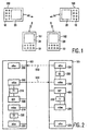
- the upper part of figure 10 illustrates an example of a series of four message frames, in which the SEQ field of successive message frames comprises a sequentially higher number.
- the first message frame 500 comprises the number zero; the second message frame 501 a one; and so on.
- the lower part of figure 10 illustrates an alternative approach in which the SEQ field is subdivided into three sub-fields T, F and L.
- the T field comprises altematingly the number zero or one (toggle bit) for successive message frames of a series. This allows to differentiate between successive message frames. The situation could occur, however, that an even number of successive message frames are not received correctly by a particular apparatus. This apparatus would not be able to detect that.
- the first message frame comprises a length indicator, which indicates the total number of message frames in the series.
- the length indicator could, for instance, be part of the data in the DATA field.
- the SEQ field comprises a sub-field F, of at least one bit, for indicating this.
- the SEQ field comprises a sub-field L, of at least one bit, for indicating that the message frame is the last of a series.
- a simple checksum such as the described length indicator, protects against a limited number of errors. For some systems this level of protection may not be sufficient. For infrared based communication, particularly using portable apparatuses, optical contact can easily be broken. Without precautions this could result in the following scenario: an apparatus A starts transmitting a series of six message frames, with the length being indicated in the first frame. Apparatus B receives the message frames. Apparatus C does not receive the beginning of the series and starts transmitting a series of four message frames (for example, the user only points C towards the other apparatuses when C needs to transmit a message) at the moment when A has only transmitted two message frames. Both apparatus A and B detect the series of message frames transmitted by C.
- a length checksum does not allow B to detect that the series is not correct. If required, more advanced checksums can be used, such as parity-based checksums or cyclic redundancy checks (CRC).
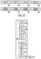
- Figure 11 shows a further embodiment in which apparatus 100 comprises checksum calculation means 410 for calculating a checksum representing a series of frames.
- the checksum could be a CRC calculated over the entire contents of all message frames of the series. It will be appreciated that the checksum may also be simpler and limited to defined fields of the message frame, such as the data field only.
- the message sending means 200 is adapted to use the checksum calculation means 410 to calculate a checksum over the series of message frames, which the message sending means 200 needs to transmit.
- the message sending means 200 then inserts the checksum at a predetermined position in a predetermined message frame. Obviously, many different positions can be chosen, such as the first position of the data field of the first message frame of the series or the last position of the last message frame.
- the series of message frames is received by the message receiving means 210 of one or more other apparatuses.
- the message receiving means 210 is adapted to use the checksum calculation means 410 to calculate a checksum over the received series of message frames.
- the message receiving means 210 also extracts the checksum from the predetermined position in the predetermined message frame.
- the acknowledge sending means 220 is adapted to only transmit an acknowledgement frame for the last message frame of the series if both checksums match. Depending on the choice of the checksum, this may ensure sufficient protection against errors, such as basic transmission errors (resulting in some bits being received wrongly), loss of message frames and concatenation of message frames transmitted by different apparatuses.
- the micro-controller can advantageously be used to calculate the checksum.
Abstract
Description
said sending apparatus comprising message sending means for transmitting a message frame, and acknowledge receiving means for receiving an acknowledgement frame; and
said receiving apparatus comprising message receiving means for receiving a message frame, and acknowledge sending means for transmitting an acknowledgement frame upon said message receiving means correctly receiving a message frame,
each apparatus further comprising:
said acknowledge sending means being adapted to transmit an acknowledgement frame only if said second timer expires prior to said detection means detecting a transmission of another frame.
- A random delay, governed by a second timer, is used before transmitting the acknowledgement frame. The timer is set upon receipt of a message frame. This reduces the chance of a plurality of apparatuses nearly-simultaneously starting the transmission of an acknowledged frame. The random delay has an upper boundary, which is less than the first time, ensuring that the transmission of the acknowledgement frame starts before the transmission of another message frame.
- The apparatuses detect (sense) whether a frame is transmitted during the random delay period. If so (implying that another apparatus had a shorter delay and has already started transmitting an acknowledgement frame), no other acknowledgement frame is transmitted.
in that said message sending means is adapted to divide a long message over a series of message frames and to sequentially transmit said series of message frames; each successive message frame of the series being different from the immediately preceding message frame and a successive message frame being transmitted after an acknowledgement frame for the immediately preceding message frame has been received by said acknowledge receiving means;
in that said message receiving means is adapted to receive a series of message frames and to distinguish between successive message frames of the series; and
in that said acknowledge sending means is adapted to transmit said acknowledgement frame, upon said message receiving means correctly receiving a message frame of said series, only if said message receiving means has correctly received all preceding message frames of said series.
each apparatus comprises checksum calculation means for calculating a checksum representing a series of message frames;
said message sending means is adapted to cause said checksum calculation means to calculate a first checksum representing the series of message frames to be transmitted by said message sending means; said message sending means inserting said first checksum in a predetermined message frame of the series;
said message sending means is further adapted to insert in the last message frame of the series an indication that this message frame is the last message frame of the series;
said message receiving means is adapted to cause said checksum calculation means to calculate a second checksum representing the series of message frames received by said message receiving means;
said acknowledge sending means is adapted to, upon said message receiving means receiving the last message frame of the series, transmit said acknowledgement frame only if said first checksum comprised in said predetermined message frame of the series received by said message receiving means matches said second checksum.
Claims (9)
- A wireless communication system comprising a sending apparatus and a receiving apparatus;
said sending apparatus comprising message sending means (200) for transmitting a message frame (500), and acknowledge receiving means (230) for receiving an acknowledgement frame (510); and
said receiving apparatus comprising message receiving means (210) for receiving a message frame (500), and acknowledge sending means (220) for transmitting an acknowledgement frame (510) upon said message receiving means (210) correctly receiving a message frame (500),
characterized:in that said system comprises at least three apparatuses (100-103); each apparatus (100-103) being a sending apparatus as well as a receiving apparatus,each apparatus (100-103) further comprising:detection means (400) for detecting a transmission of a frame (500, 510),first timing means (310) for setting a first timer at a predetermined first time (T1) upon said detection means (400) detecting the ending of said transmission, andsecond timing means (320) for, upon said message receiving means (210) correctly receiving a message frame (500), setting a second timer at a random time with a predetermined upper boundary (T2); said predetermined upper boundary (T2) being smaller than said first time (T1);said message sending means (200) being adapted to transmit a message frame (500) when said first timer is expired and said detection means (400) detect no transmission of another frame (500, 510); andsaid acknowledge sending means (220) being adapted to transmit an acknowledgement frame (510) only if said second timer expires prior to said detection means (400) detecting a transmission of another frame (500, 510). - A system as claimed in claim 1, characterized in that said first timing means (310) is adapted to set said first timer at a random time (T1) within a time window; said time window being chosen from a plurality of pre-determined, non-overlapping time windows, with the time window, which most closely follows said detection of the ending of a transmission of a frame (500,510), being reserved for transmitting a message frame (500) with highest priority and each successive time window being reserved for transmitting a message frame (500) with a successively lower priority.
- A system as claimed in claim 1 or 2, characterized in that:said sending apparatus further comprises third timing means (330) for setting a third timer at a predetermined third time (T3) after said message sending means (200) has transmitted a message frame (500-503);said message sending means (200) is adapted to retransmit said message frame (500-503) up to a predetermined maximum number of times if said third timer expires prior to said acknowledge receiving means (230) receiving an acknowledgement frame (510);said message sending means (200) is adapted to divide a long message over a series of message frames (500-503) and to sequentially transmit said series of message frames (500-503); each successive message frame of the series being different from the immediately preceding message frame and a successive message frame being transmitted after an acknowledgement frame (510) for the immediately preceding message frame has been received by said acknowledge receiving means (230);said message receiving means (210) is adapted to receive a series of message frames (500-503) and to distinguish between successive message frames of the series; andsaid acknowledge sending means (220) is adapted to transmit said acknowledgement frame (510), upon said message receiving means (210) correctly receiving a message frame of said series (500-503), only if said message receiving means has correctly received all preceding message frames of said series (500-503).
- A system as claimed in claim 3, characterized in that said acknowledge sending means (220) is adapted to transmit said acknowledgement frame (510) only if said acknowledge sending means (220) has transmitted an acknowledgement frame (510) for all preceding message frames of said series (500-503).
- A system as claimed in claim 2 and 3, characterized in that a message frame (500), which is the first of a series of message frames (500-503), is assigned a lower priority than the remaining message frames of the series (501-503).
- A system as claimed in claim 3, 4 or 5, characterized in that message frames of a series of message frames (500-503) comprise a number (SEQ.) which is different for successive message frames of the series (500-503).
- A system as claimed in claim 6, characterized in that successive message frames of the series (500-503) alternatingly comprise the number zero or one.
- A system as claimed in claim 3, 4, 5, 6 or 7, characterized in that:each apparatus (100-103) comprises checksum calculation means (410) for calculating a checksum representing a series of message frames (500-503);said message sending means (200) is adapted to cause said checksum calculation means (410) to calculate a first checksum representing the series of message frames (500-503) to be transmitted by said message sending means (200); said message sending means (200) inserting said first checksum in a predetermined message frame of the series;said message sending means (200) is further adapted to insert in the last message frame (503) of the series (500-503) an indication that this message frame is the last message frame (503) of the series;said message receiving means (210) is adapted to cause said checksum calculation means (410) to calculate a second checksum representing the series of message frames (500-503) received by said message receiving means (210);said acknowledge sending means (220) is adapted to, upon said message receiving means (210) receiving the last message frame (503) of the series (500-503), transmit said acknowledgement frame (510) only if said first checksum comprised in said predetermined message frame of the series (500-503) received by said message receiving means (220) matches said second checksum.
- An apparatus (100-103) for use in a wireless communication system, said apparatus (100-103) comprising:characterized:message sending means (200) for transmitting a message frame (500);acknowledge receiving means (230) for receiving an acknowledgement frame (510);message receiving means (210) for receiving a message frame (500); andacknowledge sending means (220) for transmitting an acknowledgement frame (510) upon said message receiving means (210) correctly receiving a message frame (500),in that said apparatus (100-103) further comprises:detection means (400) for detecting a transmission of a frame (500, 510),first timing means (310) for setting a first timer at a predetermined first time (T1) upon said detection means (400) detecting the ending of said transmission, andsecond timing means (320) for, upon said message receiving means (210) correctly receiving a message frame (500), setting a second timer at a random time with a predetermined upper boundary (T2); said predetermined upper boundary (T2) being smaller than said first time (T1);said message sending means (200) being adapted to transmit a message frame (500) when said first timer is expired and said detection means (400) detect no transmission of another frame (500,510); andsaid acknowledge sending means (220) being adapted to transmit an acknowledgement frame (510) only if said second timer expires prior to said detection means (400) detecting a transmission of another frame (500, 510).
Priority Applications (1)
| Application Number | Priority Date | Filing Date | Title |
|---|---|---|---|
| EP96907614A EP0767945B1 (en) | 1995-04-28 | 1996-04-10 | Wireless communication system for reliable communication between a group of apparatuses |
Applications Claiming Priority (4)
| Application Number | Priority Date | Filing Date | Title |
|---|---|---|---|
| EP95201102 | 1995-04-28 | ||
| EP95201102 | 1995-04-28 | ||
| PCT/IB1996/000305 WO1996034374A2 (en) | 1995-04-28 | 1996-04-10 | Wireless communication system for reliable communication between a group of apparatuses |
| EP96907614A EP0767945B1 (en) | 1995-04-28 | 1996-04-10 | Wireless communication system for reliable communication between a group of apparatuses |
Publications (2)
| Publication Number | Publication Date |
|---|---|
| EP0767945A2 EP0767945A2 (en) | 1997-04-16 |
| EP0767945B1 true EP0767945B1 (en) | 2004-06-30 |
Family
ID=8220232
Family Applications (1)
| Application Number | Title | Priority Date | Filing Date |
|---|---|---|---|
| EP96907614A Expired - Lifetime EP0767945B1 (en) | 1995-04-28 | 1996-04-10 | Wireless communication system for reliable communication between a group of apparatuses |
Country Status (8)
| Country | Link |
|---|---|
| US (1) | US5797085A (en) |
| EP (1) | EP0767945B1 (en) |
| JP (1) | JPH10502789A (en) |
| KR (1) | KR100420885B1 (en) |
| CN (1) | CN1143473C (en) |
| DE (1) | DE69632808T2 (en) |
| TW (1) | TW309676B (en) |
| WO (1) | WO1996034374A2 (en) |
Families Citing this family (205)
| Publication number | Priority date | Publication date | Assignee | Title |
|---|---|---|---|---|
| EP0811216B1 (en) * | 1995-12-22 | 2002-09-04 | Koninklijke Philips Electronics N.V. | System for communicating between a group of apparatuses |
| GB9611146D0 (en) * | 1996-05-29 | 1996-07-31 | Philips Electronics Nv | Method of, and system for, transmitting messages |
| JP3375257B2 (en) * | 1996-10-28 | 2003-02-10 | 株式会社日立製作所 | Information processing device |
| JPH10200934A (en) * | 1997-01-10 | 1998-07-31 | Matsushita Electric Ind Co Ltd | Pager |
| DE69831475T2 (en) * | 1997-04-24 | 2006-06-29 | Sony Computer Entertainment Inc. | MEMORY CARD SETUP, VIDEO TOR SETUP, AND PROGRAMMING MEDIA |
| US6075779A (en) * | 1997-06-09 | 2000-06-13 | Lucent Technologies, Inc. | Random access channel congestion control for broadcast teleservice acknowledgment messages |
| DE19812423A1 (en) * | 1998-03-20 | 1999-09-23 | Moeller Gmbh | Programmable controller with control button as active button is highly reliable, convenient to operate and enables its switching program to be checked for correct operation without outside aids |
| JP2000194726A (en) * | 1998-10-19 | 2000-07-14 | Sony Corp | Device, method and system for processing information and providing medium |
| JP3420953B2 (en) * | 1998-12-11 | 2003-06-30 | 株式会社ソニー・コンピュータエンタテインメント | Entertainment system and recording medium |
| FR2787663B1 (en) * | 1998-12-18 | 2001-03-23 | Canon Kk | DATA ACQUISITION IN A DATA COMMUNICATION SYSTEM |
| KR100323389B1 (en) * | 1999-04-28 | 2002-02-19 | 오정훈 | A hand-held wireless entertainment system and a method thereof |
| US6524189B1 (en) | 1999-07-09 | 2003-02-25 | Nokia Corporation | Multi-player game system using mobile telephone and game unit |
| US6893347B1 (en) * | 1999-07-09 | 2005-05-17 | Nokia Corporation | Method and apparatus for playing games between the clients of entities at different locations |
| US7889052B2 (en) | 2001-07-10 | 2011-02-15 | Xatra Fund Mx, Llc | Authorizing payment subsequent to RF transactions |
| US7837116B2 (en) | 1999-09-07 | 2010-11-23 | American Express Travel Related Services Company, Inc. | Transaction card |
| US7239226B2 (en) | 2001-07-10 | 2007-07-03 | American Express Travel Related Services Company, Inc. | System and method for payment using radio frequency identification in contact and contactless transactions |
| EP1087323A1 (en) * | 1999-09-24 | 2001-03-28 | Nokia Corporation | A wireless system for interacting with a virtual space |
| US6527641B1 (en) | 1999-09-24 | 2003-03-04 | Nokia Corporation | System for profiling mobile station activity in a predictive command wireless game system |
| US6554707B1 (en) | 1999-09-24 | 2003-04-29 | Nokia Corporation | Interactive voice, wireless game system using predictive command input |
| FI19992470A (en) * | 1999-11-17 | 2001-05-18 | Nokia Mobile Phones Ltd | Communication |
| DE19959387A1 (en) * | 1999-12-09 | 2001-06-13 | Philipp Paul Spangenberg | Communicating between electronic computer unit, personal digital assistants involves fitting computer unit and personal digital assistants with ordinary infrared transmission and reception units |
| US6287200B1 (en) * | 1999-12-15 | 2001-09-11 | Nokia Corporation | Relative positioning and virtual objects for mobile devices |
| US6674995B1 (en) * | 1999-12-22 | 2004-01-06 | Nokia Corporation | Electronically augmented multiplayer sporting game with virtual ball passed by infrared apparatus |
| US7172112B2 (en) | 2000-01-21 | 2007-02-06 | American Express Travel Related Services Company, Inc. | Public/private dual card system and method |
| US8543423B2 (en) | 2002-07-16 | 2013-09-24 | American Express Travel Related Services Company, Inc. | Method and apparatus for enrolling with multiple transaction environments |
| US8429041B2 (en) | 2003-05-09 | 2013-04-23 | American Express Travel Related Services Company, Inc. | Systems and methods for managing account information lifecycles |
| FI110352B (en) | 2000-02-24 | 2002-12-31 | Nokia Corp | Method and arrangement to optimize the re-establishment of connections in a cellular radio system that supports real-time and non-real-time communications |
| WO2001067355A2 (en) | 2000-03-07 | 2001-09-13 | American Express Travel Related Services Company, Inc. | System for facilitating a transaction |
| US8876608B2 (en) * | 2000-04-07 | 2014-11-04 | Igt | Virtually tracking un-carded or anonymous patron session data |
| US6676522B2 (en) | 2000-04-07 | 2004-01-13 | Igt | Gaming system including portable game devices |
| US6682421B1 (en) * | 2000-04-07 | 2004-01-27 | Igt | Wireless gaming environment |
| US7927211B2 (en) * | 2002-04-02 | 2011-04-19 | Igt | Gaming environment including portable transaction devices |
| US7883417B2 (en) * | 2000-04-07 | 2011-02-08 | Igt | Gaming machine communicating system |
| ES2211794T3 (en) * | 2000-04-10 | 2004-07-16 | Zensys A/S | RADIO FREQUENCY HOME AUTOMATION SYSTEM WITH CONTROLLERS THAT CAN BE DUPLICATED. |
| JP3661992B2 (en) * | 2000-08-21 | 2005-06-22 | 株式会社ユニレック | Equipment management system |
| US6799035B1 (en) * | 2000-09-12 | 2004-09-28 | Jeffrey Cousins | Apparatus and process for sending a wireless directional signal containing personal information |
| US6875110B1 (en) | 2000-10-17 | 2005-04-05 | Igt | Multi-system gaming terminal communication device |
| US8790181B2 (en) * | 2000-10-17 | 2014-07-29 | Igt | Multi-system gaming terminal communication device |
| US6618683B1 (en) | 2000-12-12 | 2003-09-09 | International Business Machines Corporation | Method and apparatus for calibrating an accelerometer-based navigation system |
| US6879810B2 (en) * | 2000-12-20 | 2005-04-12 | Nokia Corporation | Control of short range RF communication |
| US7107236B2 (en) * | 2001-01-02 | 2006-09-12 | ★Roaming Messenger, Inc. | Self-contained business transaction capsules |
| US6908389B1 (en) * | 2001-03-07 | 2005-06-21 | Nokia Corporation | Predefined messages for wireless multiplayer gaming |
| US7063619B2 (en) * | 2001-03-29 | 2006-06-20 | Interactive Telegames, Llc | Method and apparatus for identifying game players and game moves |
| US7068294B2 (en) | 2001-03-30 | 2006-06-27 | Koninklijke Philips Electronics N.V. | One-to-one direct communication |
| US6682423B2 (en) * | 2001-04-19 | 2004-01-27 | Igt | Open architecture communications in a gaming network |
| US20020174248A1 (en) * | 2001-05-16 | 2002-11-21 | Motorola, Inc. | Method and system for communicating chat and game messages in a wireless network |
| US7650314B1 (en) | 2001-05-25 | 2010-01-19 | American Express Travel Related Services Company, Inc. | System and method for securing a recurrent billing transaction |
| US7725427B2 (en) | 2001-05-25 | 2010-05-25 | Fred Bishop | Recurrent billing maintenance with radio frequency payment devices |
| US20020183118A1 (en) * | 2001-05-30 | 2002-12-05 | Scott Wolinsky | Method and apparatus for simulating game accessories |
| GB2375970B (en) * | 2001-05-31 | 2005-11-23 | Nokia Corp | Electronic gaming |
| CA2450439A1 (en) | 2001-06-15 | 2002-12-27 | Salary.Com | Compensation data prediction |
| US8282475B2 (en) | 2001-06-15 | 2012-10-09 | Igt | Virtual leash for personal gaming device |
| US8087988B2 (en) | 2001-06-15 | 2012-01-03 | Igt | Personal gaming device and method of presenting a game |
| WO2002102484A1 (en) | 2001-06-15 | 2002-12-27 | Walker Digital, Llc | Method and apparatus for planning and customizing a gaming experience |
| US7918728B2 (en) | 2001-06-15 | 2011-04-05 | Igt | Personal gaming device and method of presenting a game |
| WO2003003194A1 (en) | 2001-06-27 | 2003-01-09 | Sony Corporation | Integrated circuit device, information processing device, information recording device memory management method, mobile terminal device, semiconductor integrated circuit device, and communication method using mobile terminal device |
| DE10132472A1 (en) * | 2001-07-04 | 2003-02-06 | Atronic Int Gmbh | Play equipment plant |
| US9024719B1 (en) | 2001-07-10 | 2015-05-05 | Xatra Fund Mx, Llc | RF transaction system and method for storing user personal data |
| US8548927B2 (en) | 2001-07-10 | 2013-10-01 | Xatra Fund Mx, Llc | Biometric registration for facilitating an RF transaction |
| US7249112B2 (en) | 2002-07-09 | 2007-07-24 | American Express Travel Related Services Company, Inc. | System and method for assigning a funding source for a radio frequency identification device |
| US8294552B2 (en) | 2001-07-10 | 2012-10-23 | Xatra Fund Mx, Llc | Facial scan biometrics on a payment device |
| US9031880B2 (en) | 2001-07-10 | 2015-05-12 | Iii Holdings 1, Llc | Systems and methods for non-traditional payment using biometric data |
| US7360689B2 (en) | 2001-07-10 | 2008-04-22 | American Express Travel Related Services Company, Inc. | Method and system for proffering multiple biometrics for use with a FOB |
| US7503480B2 (en) | 2001-07-10 | 2009-03-17 | American Express Travel Related Services Company, Inc. | Method and system for tracking user performance |
| US9454752B2 (en) | 2001-07-10 | 2016-09-27 | Chartoleaux Kg Limited Liability Company | Reload protocol at a transaction processing entity |
| US7762457B2 (en) | 2001-07-10 | 2010-07-27 | American Express Travel Related Services Company, Inc. | System and method for dynamic fob synchronization and personalization |
| US7746215B1 (en) | 2001-07-10 | 2010-06-29 | Fred Bishop | RF transactions using a wireless reader grid |
| US7805378B2 (en) | 2001-07-10 | 2010-09-28 | American Express Travel Related Servicex Company, Inc. | System and method for encoding information in magnetic stripe format for use in radio frequency identification transactions |
| US7925535B2 (en) | 2001-07-10 | 2011-04-12 | American Express Travel Related Services Company, Inc. | System and method for securing RF transactions using a radio frequency identification device including a random number generator |
| US7668750B2 (en) | 2001-07-10 | 2010-02-23 | David S Bonalle | Securing RF transactions using a transactions counter |
| US8279042B2 (en) | 2001-07-10 | 2012-10-02 | Xatra Fund Mx, Llc | Iris scan biometrics on a payment device |
| US7493288B2 (en) | 2001-07-10 | 2009-02-17 | Xatra Fund Mx, Llc | RF payment via a mobile device |
| US8538863B1 (en) | 2001-07-10 | 2013-09-17 | American Express Travel Related Services Company, Inc. | System and method for facilitating a transaction using a revolving use account associated with a primary account |
| US8960535B2 (en) | 2001-07-10 | 2015-02-24 | Iii Holdings 1, Llc | Method and system for resource management and evaluation |
| US7303120B2 (en) | 2001-07-10 | 2007-12-04 | American Express Travel Related Services Company, Inc. | System for biometric security using a FOB |
| US7705732B2 (en) | 2001-07-10 | 2010-04-27 | Fred Bishop | Authenticating an RF transaction using a transaction counter |
| US7827106B2 (en) | 2001-07-10 | 2010-11-02 | American Express Travel Related Services Company, Inc. | System and method for manufacturing a punch-out RFID transaction device |
| US7996324B2 (en) | 2001-07-10 | 2011-08-09 | American Express Travel Related Services Company, Inc. | Systems and methods for managing multiple accounts on a RF transaction device using secondary identification indicia |
| US8001054B1 (en) | 2001-07-10 | 2011-08-16 | American Express Travel Related Services Company, Inc. | System and method for generating an unpredictable number using a seeded algorithm |
| US20040236699A1 (en) | 2001-07-10 | 2004-11-25 | American Express Travel Related Services Company, Inc. | Method and system for hand geometry recognition biometrics on a fob |
| US8635131B1 (en) | 2001-07-10 | 2014-01-21 | American Express Travel Related Services Company, Inc. | System and method for managing a transaction protocol |
| US7119659B2 (en) | 2001-07-10 | 2006-10-10 | American Express Travel Related Services Company, Inc. | Systems and methods for providing a RF transaction device for use in a private label transaction |
| US20030054846A1 (en) * | 2001-09-14 | 2003-03-20 | Cvsht | Apparatus and methods for selectively establishing wireless communications |
| US7611409B2 (en) * | 2001-09-20 | 2009-11-03 | Igt | Method and apparatus for registering a mobile device with a gaming machine |
| US7699703B2 (en) * | 2001-09-20 | 2010-04-20 | Igt | Method and apparatus for registering a mobile device with a gaming machine |
| US6846238B2 (en) * | 2001-09-28 | 2005-01-25 | Igt | Wireless game player |
| FR2835997B1 (en) * | 2002-02-11 | 2004-11-26 | Somfy | METHOD FOR DEFINING A GROUP AMONG BIDIRECTIONAL OBJECTS |
| FR2835982B1 (en) * | 2002-02-11 | 2016-04-29 | Somfy | METHOD FOR MATCHING BIDIRECTIONAL OBJECTS |
| US8221224B2 (en) | 2002-02-28 | 2012-07-17 | Igt | Method for distributing large payouts with minimal interruption of a gaming session |
| US7225280B2 (en) * | 2002-02-28 | 2007-05-29 | Sandisk Il Ltd. | Portable device for one-on-one transfer between another such device wherein device is restricted to data storage and transfer with single interface for data exchange |
| US20030174681A1 (en) * | 2002-03-18 | 2003-09-18 | Philippe Gilberton | Method and apparatus for indicating the presence of a wireless local area network by detecting energy fluctuations |
| CN1447234A (en) * | 2002-03-27 | 2003-10-08 | 株式会社唯红 | Personal authenticator, sale management device |
| US8540562B2 (en) | 2002-03-29 | 2013-09-24 | Igt | Advantage bingo bonus |
| US7785193B2 (en) * | 2002-03-29 | 2010-08-31 | Igt | Cashless bonusing for gaming machines |
| TWI221571B (en) * | 2002-04-26 | 2004-10-01 | Unirec Co Ltd | Content delivering system |
| US20030211888A1 (en) * | 2002-05-13 | 2003-11-13 | Interactive Telegames, Llc | Method and apparatus using insertably-removable auxiliary devices to play games over a communications link |
| US7815507B2 (en) | 2004-06-18 | 2010-10-19 | Igt | Game machine user interface using a non-contact eye motion recognition device |
| US8460103B2 (en) | 2004-06-18 | 2013-06-11 | Igt | Gesture controlled casino gaming system |
| JP3955512B2 (en) * | 2002-08-27 | 2007-08-08 | 富士通株式会社 | Data processing apparatus and packet discrimination method |
| US6805287B2 (en) | 2002-09-12 | 2004-10-19 | American Express Travel Related Services Company, Inc. | System and method for converting a stored value card to a credit card |
| US20040063498A1 (en) * | 2002-09-30 | 2004-04-01 | Sony Corporation | System and method for flexibly implementing a wireless gaming network |
| US7344443B2 (en) * | 2002-10-24 | 2008-03-18 | Unirec Co., Ltd. | Game system using tokens |
| US6898414B2 (en) * | 2002-10-28 | 2005-05-24 | Motorola, Inc. | Method for acknowledging messages in a communication system |
| JP4970933B2 (en) * | 2003-03-05 | 2012-07-11 | コーニンクレッカ フィリップス エレクトロニクス エヌ ヴィ | Acknowledgment timed out frame synchronization in wireless networks |
| US7341522B2 (en) * | 2003-03-21 | 2008-03-11 | Unirec Co., Ltd. | Game system with gaming machine interconnected to a cellular phone |
| US7096006B2 (en) * | 2003-03-24 | 2006-08-22 | Inventec Appliances Corp. | Method of playing instant game on wireless network terminal device |
| US20050003759A1 (en) * | 2003-06-19 | 2005-01-06 | Alley Kenneth A. | Anonymous communication device |
| US8512144B2 (en) | 2003-10-20 | 2013-08-20 | Tipping Point Group, Llc | Method and apparatus for providing secondary gaming machine functionality |
| US20050102701A1 (en) * | 2003-11-12 | 2005-05-12 | Lin Charlie K. | Attention parental switch system of video/audio device |
| DE602004013272T2 (en) * | 2004-02-19 | 2009-07-16 | Alcatel Lucent | Method, server and mobile terminal for establishing connections between subscribers of a telecommunications network |
| US7347781B2 (en) * | 2004-03-03 | 2008-03-25 | Motorola, Inc. | Method and system for reality gaming on wireless devices |
| JP4469653B2 (en) * | 2004-05-06 | 2010-05-26 | 任天堂株式会社 | Game system and game program |
| JP4762504B2 (en) * | 2004-05-07 | 2011-08-31 | 任天堂株式会社 | GAME DEVICE, GAME PROGRAM, GAME CONTROL METHOD, AND GAME SYSTEM |
| US8684839B2 (en) | 2004-06-18 | 2014-04-01 | Igt | Control of wager-based game using gesture recognition |
| US7318550B2 (en) | 2004-07-01 | 2008-01-15 | American Express Travel Related Services Company, Inc. | Biometric safeguard method for use with a smartcard |
| US7942744B2 (en) | 2004-08-19 | 2011-05-17 | Igt | Virtual input system |
| US8049594B1 (en) | 2004-11-30 | 2011-11-01 | Xatra Fund Mx, Llc | Enhanced RFID instrument security |
| US8062121B2 (en) | 2005-03-09 | 2011-11-22 | Igt | Printer interpreter for a gaming machine |
| US7867095B2 (en) * | 2005-06-17 | 2011-01-11 | Igt | Candle radio |
| US8052526B2 (en) * | 2005-09-09 | 2011-11-08 | Igt | Method and apparatus for peer-to-peer wagering game |
| US8992304B2 (en) | 2006-04-13 | 2015-03-31 | Igt | Methods and systems for tracking an event of an externally controlled interface |
| US8784196B2 (en) | 2006-04-13 | 2014-07-22 | Igt | Remote content management and resource sharing on a gaming machine and method of implementing same |
| US9028329B2 (en) | 2006-04-13 | 2015-05-12 | Igt | Integrating remotely-hosted and locally rendered content on a gaming device |
| US10026255B2 (en) | 2006-04-13 | 2018-07-17 | Igt | Presentation of remotely-hosted and locally rendered content for gaming systems |
| US9205329B2 (en) * | 2006-07-25 | 2015-12-08 | Mga Entertainment, Inc. | Virtual world electronic game |
| US8226474B2 (en) | 2006-09-08 | 2012-07-24 | Igt | Mobile gaming devices for use in a gaming network having gaming and non-gaming zones |
| US20090156303A1 (en) | 2006-11-10 | 2009-06-18 | Igt | Bonusing Architectures in a Gaming Environment |
| US9311774B2 (en) | 2006-11-10 | 2016-04-12 | Igt | Gaming machine with externally controlled content display |
| US8362503B2 (en) * | 2007-03-09 | 2013-01-29 | Cree, Inc. | Thick nitride semiconductor structures with interlayer structures |
| JP5116514B2 (en) * | 2008-03-11 | 2013-01-09 | キヤノン株式会社 | Imaging apparatus and display control method |
| US8773336B2 (en) | 2008-09-05 | 2014-07-08 | Ketra, Inc. | Illumination devices and related systems and methods |
| US9509525B2 (en) | 2008-09-05 | 2016-11-29 | Ketra, Inc. | Intelligent illumination device |
| US9276766B2 (en) | 2008-09-05 | 2016-03-01 | Ketra, Inc. | Display calibration systems and related methods |
| US10210750B2 (en) | 2011-09-13 | 2019-02-19 | Lutron Electronics Co., Inc. | System and method of extending the communication range in a visible light communication system |
| US8315930B2 (en) | 2008-12-22 | 2012-11-20 | General Electric Company | Systems and methods for charging an electric vehicle using broadband over powerlines |
| US20100156349A1 (en) * | 2008-12-22 | 2010-06-24 | Nathan Bowman Littrell | System and method for pay as you go charging for electric vehicles |
| US20100161393A1 (en) * | 2008-12-22 | 2010-06-24 | Nathan Bowman Littrell | Systems and methods for charging an electric vehicle within a parking area |
| US9505317B2 (en) * | 2008-12-22 | 2016-11-29 | General Electric Company | System and method for electric vehicle charging and billing using a wireless vehicle communication service |
| US9396462B2 (en) * | 2008-12-22 | 2016-07-19 | General Electric Company | System and method for roaming billing for electric vehicles |
| US9030153B2 (en) * | 2008-12-22 | 2015-05-12 | General Electric Company | Systems and methods for delivering energy to an electric vehicle with parking fee collection |
| US8583551B2 (en) * | 2008-12-22 | 2013-11-12 | General Electric Company | Systems and methods for prepaid electric metering for vehicles |
| US9586139B2 (en) * | 2009-03-03 | 2017-03-07 | Mobilitie, Llc | System and method for game play in a dynamic communication network |
| JP2011018114A (en) * | 2009-07-07 | 2011-01-27 | Canon Inc | Reception apparatus, transmission apparatus, reception method, transmission method, and program |
| US8892138B2 (en) * | 2009-11-27 | 2014-11-18 | Telefonaktiebolaget L M Ericsson (Publ) | Transferring messages in a communications network |
| US8458597B1 (en) * | 2010-02-04 | 2013-06-04 | Adobe Systems Incorporated | Systems and methods that facilitate the sharing of electronic assets |
| US9607505B2 (en) * | 2010-09-22 | 2017-03-28 | Apple Inc. | Closed loop universal remote control |
| US9386668B2 (en) | 2010-09-30 | 2016-07-05 | Ketra, Inc. | Lighting control system |
| USRE49454E1 (en) | 2010-09-30 | 2023-03-07 | Lutron Technology Company Llc | Lighting control system |
| US8753194B2 (en) | 2010-11-11 | 2014-06-17 | Igt | Escrow accounts for use in distributing payouts with minimal interruption to game play |
| US9875607B2 (en) | 2011-07-13 | 2018-01-23 | Igt | Methods and apparatus for providing secure logon to a gaming machine using a mobile device |
| US9367835B2 (en) | 2011-09-09 | 2016-06-14 | Igt | Retrofit devices for providing virtual ticket-in and ticket-out on a gaming machine |
| US8613659B2 (en) | 2011-09-09 | 2013-12-24 | Igt | Virtual ticket-in and ticket-out on a gaming machine |
| US10297105B2 (en) | 2011-09-09 | 2019-05-21 | Igt | Redemption of virtual tickets using a portable electronic device |
| US10121318B2 (en) | 2011-09-09 | 2018-11-06 | Igt | Bill acceptors and printers for providing virtual ticket-in and ticket-out on a gaming machine |
| US20190272704A1 (en) | 2011-09-09 | 2019-09-05 | Igt | Redemption of virtual tickets using a portable electronic device |
| US9524609B2 (en) | 2011-09-30 | 2016-12-20 | Igt | Gaming system, gaming device and method for utilizing mobile devices at a gaming establishment |
| US8613668B2 (en) | 2011-12-22 | 2013-12-24 | Igt | Directional wireless communication |
| US8876596B2 (en) | 2012-02-29 | 2014-11-04 | Igt | Virtualized magnetic player card |
| US9201719B2 (en) | 2012-03-16 | 2015-12-01 | Infineon Technologies Ag | Method and system for timeout monitoring |
| US9311769B2 (en) | 2012-03-28 | 2016-04-12 | Igt | Emailing or texting as communication between mobile device and EGM |
| US9412227B2 (en) | 2012-07-11 | 2016-08-09 | Igt | Method and apparatus for offering a mobile device version of an electronic gaming machine game at the electronic gaming machine |
| US9237620B1 (en) | 2013-08-20 | 2016-01-12 | Ketra, Inc. | Illumination device and temperature compensation method |
| USRE48956E1 (en) | 2013-08-20 | 2022-03-01 | Lutron Technology Company Llc | Interference-resistant compensation for illumination devices using multiple series of measurement intervals |
| US9345097B1 (en) | 2013-08-20 | 2016-05-17 | Ketra, Inc. | Interference-resistant compensation for illumination devices using multiple series of measurement intervals |
| US9578724B1 (en) | 2013-08-20 | 2017-02-21 | Ketra, Inc. | Illumination device and method for avoiding flicker |
| US9155155B1 (en) | 2013-08-20 | 2015-10-06 | Ketra, Inc. | Overlapping measurement sequences for interference-resistant compensation in light emitting diode devices |
| US9247605B1 (en) | 2013-08-20 | 2016-01-26 | Ketra, Inc. | Interference-resistant compensation for illumination devices |
| US9769899B2 (en) | 2014-06-25 | 2017-09-19 | Ketra, Inc. | Illumination device and age compensation method |
| US9332598B1 (en) | 2013-08-20 | 2016-05-03 | Ketra, Inc. | Interference-resistant compensation for illumination devices having multiple emitter modules |
| US9651632B1 (en) | 2013-08-20 | 2017-05-16 | Ketra, Inc. | Illumination device and temperature calibration method |
| US9360174B2 (en) | 2013-12-05 | 2016-06-07 | Ketra, Inc. | Linear LED illumination device with improved color mixing |
| USRE48955E1 (en) | 2013-08-20 | 2022-03-01 | Lutron Technology Company Llc | Interference-resistant compensation for illumination devices having multiple emitter modules |
| US9736895B1 (en) | 2013-10-03 | 2017-08-15 | Ketra, Inc. | Color mixing optics for LED illumination device |
| US9146028B2 (en) | 2013-12-05 | 2015-09-29 | Ketra, Inc. | Linear LED illumination device with improved rotational hinge |
| KR101609922B1 (en) | 2014-05-21 | 2016-04-20 | 삼성에스디에스 주식회사 | Apparatus and method for peer-to-peer based data trasnfer |
| US9736903B2 (en) | 2014-06-25 | 2017-08-15 | Ketra, Inc. | Illumination device and method for calibrating and controlling an illumination device comprising a phosphor converted LED |
| US9557214B2 (en) | 2014-06-25 | 2017-01-31 | Ketra, Inc. | Illumination device and method for calibrating an illumination device over changes in temperature, drive current, and time |
| US9392663B2 (en) | 2014-06-25 | 2016-07-12 | Ketra, Inc. | Illumination device and method for controlling an illumination device over changes in drive current and temperature |
| US10161786B2 (en) | 2014-06-25 | 2018-12-25 | Lutron Ketra, Llc | Emitter module for an LED illumination device |
| US9510416B2 (en) | 2014-08-28 | 2016-11-29 | Ketra, Inc. | LED illumination device and method for accurately controlling the intensity and color point of the illumination device over time |
| US9392660B2 (en) | 2014-08-28 | 2016-07-12 | Ketra, Inc. | LED illumination device and calibration method for accurately characterizing the emission LEDs and photodetector(s) included within the LED illumination device |
| US9237612B1 (en) | 2015-01-26 | 2016-01-12 | Ketra, Inc. | Illumination device and method for determining a target lumens that can be safely produced by an illumination device at a present temperature |
| US9237623B1 (en) | 2015-01-26 | 2016-01-12 | Ketra, Inc. | Illumination device and method for determining a maximum lumens that can be safely produced by the illumination device to achieve a target chromaticity |
| US9485813B1 (en) | 2015-01-26 | 2016-11-01 | Ketra, Inc. | Illumination device and method for avoiding an over-power or over-current condition in a power converter |
| US9916735B2 (en) | 2015-07-22 | 2018-03-13 | Igt | Remote gaming cash voucher printing system |
| US10055930B2 (en) | 2015-08-11 | 2018-08-21 | Igt | Gaming system and method for placing and redeeming sports bets |
| US10417867B2 (en) | 2015-09-25 | 2019-09-17 | Igt | Gaming system and method for automatically transferring funds to a mobile device |
| US20170092054A1 (en) | 2015-09-25 | 2017-03-30 | Igt | Gaming system and method for utilizing a mobile device to fund a gaming session |
| US10217317B2 (en) | 2016-08-09 | 2019-02-26 | Igt | Gaming system and method for providing incentives for transferring funds to and from a mobile device |
| US10916090B2 (en) | 2016-08-23 | 2021-02-09 | Igt | System and method for transferring funds from a financial institution device to a cashless wagering account accessible via a mobile device |
| US10621824B2 (en) | 2016-09-23 | 2020-04-14 | Igt | Gaming system player identification device |
| US10332344B2 (en) | 2017-07-24 | 2019-06-25 | Igt | System and method for controlling electronic gaming machine/electronic gaming machine component bezel lighting to indicate different wireless connection statuses |
| US10380843B2 (en) | 2017-08-03 | 2019-08-13 | Igt | System and method for tracking funds from a plurality of funding sources |
| US10360761B2 (en) | 2017-08-03 | 2019-07-23 | Igt | System and method for providing a gaming establishment account pre-approved access to funds |
| US10373430B2 (en) | 2017-08-03 | 2019-08-06 | Igt | System and method for tracking fund transfers between an electronic gaming machine and a plurality of funding sources |
| US10360763B2 (en) | 2017-08-03 | 2019-07-23 | Igt | System and method for utilizing a mobile device to facilitate fund transfers between a cashless wagering account and a gaming establishment retail account |
| US11341817B2 (en) | 2017-12-18 | 2022-05-24 | Igt | System and method for providing awards for utilizing a mobile device in association with a gaming establishment retail account |
| US10643426B2 (en) | 2017-12-18 | 2020-05-05 | Igt | System and method for providing a gaming establishment account automatic access to funds |
| US11922765B2 (en) | 2017-12-18 | 2024-03-05 | Igt | System and method employing virtual tickets |
| US10950088B2 (en) | 2017-12-21 | 2021-03-16 | Igt | System and method for utilizing virtual ticket vouchers |
| US11043066B2 (en) | 2017-12-21 | 2021-06-22 | Igt | System and method for centralizing funds to a primary gaming establishment account |
| US10970968B2 (en) | 2018-04-18 | 2021-04-06 | Igt | System and method for incentivizing the maintenance of funds in a gaming establishment account |
| US11272599B1 (en) | 2018-06-22 | 2022-03-08 | Lutron Technology Company Llc | Calibration procedure for a light-emitting diode light source |
| US11228996B2 (en) | 2018-09-28 | 2022-01-18 | Qualcomm Incorporated | Delivery time windows for low latency communications |
| CN115298715B (en) * | 2020-03-31 | 2024-01-30 | 三菱电机株式会社 | Communication terminal, communication system, power saving control method, and storage medium |
Family Cites Families (8)
| Publication number | Priority date | Publication date | Assignee | Title |
|---|---|---|---|---|
| JPS508562A (en) * | 1973-05-21 | 1975-01-29 | ||
| US4093920A (en) * | 1976-06-29 | 1978-06-06 | Kaiser Martin L | Delayed response transmitter indicator |
| DE3508562A1 (en) * | 1985-03-11 | 1986-09-11 | Philips Patentverwaltung Gmbh, 2000 Hamburg | Method and arrangement for transmitting information |
| US4941143A (en) * | 1987-11-10 | 1990-07-10 | Echelon Systems Corp. | Protocol for network having a plurality of intelligent cells |
| JPH06101732B2 (en) * | 1987-11-30 | 1994-12-12 | 三菱電機株式会社 | Communication control method |
| JPH04269021A (en) * | 1991-02-25 | 1992-09-25 | Nec Corp | Two-way paging system |
| US5422887A (en) * | 1991-11-27 | 1995-06-06 | Ncr Corporation | Medium access protocol for wireless local area network |
| CA2103134C (en) * | 1993-11-15 | 1999-07-27 | Jeane Shu-Chun Chen | Medium access control protocol for wireless communication |
-
1996
- 1996-04-10 EP EP96907614A patent/EP0767945B1/en not_active Expired - Lifetime
- 1996-04-10 DE DE69632808T patent/DE69632808T2/en not_active Expired - Fee Related
- 1996-04-10 JP JP8532304A patent/JPH10502789A/en not_active Ceased
- 1996-04-10 KR KR1019960707615A patent/KR100420885B1/en not_active IP Right Cessation
- 1996-04-10 WO PCT/IB1996/000305 patent/WO1996034374A2/en active IP Right Grant
- 1996-04-10 CN CNB961906421A patent/CN1143473C/en not_active Expired - Fee Related
- 1996-04-18 TW TW085104651A patent/TW309676B/zh active
- 1996-04-24 US US08/637,256 patent/US5797085A/en not_active Expired - Fee Related
Also Published As
| Publication number | Publication date |
|---|---|
| KR100420885B1 (en) | 2004-06-04 |
| DE69632808T2 (en) | 2005-06-30 |
| DE69632808D1 (en) | 2004-08-05 |
| EP0767945A2 (en) | 1997-04-16 |
| CN1157069A (en) | 1997-08-13 |
| US5797085A (en) | 1998-08-18 |
| JPH10502789A (en) | 1998-03-10 |
| WO1996034374A3 (en) | 1997-01-09 |
| CN1143473C (en) | 2004-03-24 |
| WO1996034374A2 (en) | 1996-10-31 |
| TW309676B (en) | 1997-07-01 |
Similar Documents
| Publication | Publication Date | Title |
|---|---|---|
| EP0767945B1 (en) | Wireless communication system for reliable communication between a group of apparatuses | |
| EP0784837B1 (en) | System for communicating between a dynamic group of apparatuses | |
| US6864778B2 (en) | Method of preventing collision between remote control signals | |
| KR100434054B1 (en) | Polling method of radio link control | |
| US5572546A (en) | Data communications system with multilink protocol | |
| JPH0727600B2 (en) | Error correction method for infrared data communication | |
| JPH0722289B2 (en) | Station device for variable time division communication system | |
| US5378067A (en) | Network interface apparatus and method for reducing conflicts through the use of times | |
| JPH1066165A (en) | Remote control system | |
| US5001705A (en) | Protocol control circuit for data bus system | |
| KR0165440B1 (en) | Polling communication method | |
| JP3110137B2 (en) | Communication method in home wireless communication network | |
| JPH0319441A (en) | Reply timing control type arq system | |
| JP2752742B2 (en) | Packet transmission device | |
| JPS61216542A (en) | Transmission method of resending request signal | |
| JPS6235730A (en) | Resending system for error data | |
| JPH0553089B2 (en) | ||
| JPH02155335A (en) | Radio packet transmission system | |
| JPH08191337A (en) | Device and method for data transmission | |
| JPH0329216B2 (en) | ||
| JPH0837519A (en) | Radio communication method | |
| JPS61100041A (en) | Csma communication system | |
| JPH07264221A (en) | Data transmitter | |
| JPH07221774A (en) | Signal transmission method | |
| JPH0216833A (en) | Data re-transmitting system for station data transfer network |
Legal Events
| Date | Code | Title | Description |
|---|---|---|---|
| PUAI | Public reference made under article 153(3) epc to a published international application that has entered the european phase |
Free format text: ORIGINAL CODE: 0009012 |
|
| PUAK | Availability of information related to the publication of the international search report |
Free format text: ORIGINAL CODE: 0009015 |
|
| AK | Designated contracting states |
Kind code of ref document: A2 Designated state(s): DE FR GB |
|
| AK | Designated contracting states |
Kind code of ref document: A3 Designated state(s): DE FR GB |
|
| RHK1 | Main classification (correction) |
Ipc: H04L 1/16 |
|
| 17P | Request for examination filed |
Effective date: 19970502 |
|
| 17Q | First examination report despatched |
Effective date: 20030610 |
|
| GRAP | Despatch of communication of intention to grant a patent |
Free format text: ORIGINAL CODE: EPIDOSNIGR1 |
|
| GRAS | Grant fee paid |
Free format text: ORIGINAL CODE: EPIDOSNIGR3 |
|
| GRAA | (expected) grant |
Free format text: ORIGINAL CODE: 0009210 |
|
| AK | Designated contracting states |
Kind code of ref document: B1 Designated state(s): DE FR GB |
|
| REG | Reference to a national code |
Ref country code: GB Ref legal event code: FG4D |
|
| REF | Corresponds to: |
Ref document number: 69632808 Country of ref document: DE Date of ref document: 20040805 Kind code of ref document: P |
|
| ET | Fr: translation filed | ||
| PGFP | Annual fee paid to national office [announced via postgrant information from national office to epo] |
Ref country code: GB Payment date: 20050428 Year of fee payment: 10 Ref country code: FR Payment date: 20050428 Year of fee payment: 10 |
|
| PLBE | No opposition filed within time limit |
Free format text: ORIGINAL CODE: 0009261 |
|
| STAA | Information on the status of an ep patent application or granted ep patent |
Free format text: STATUS: NO OPPOSITION FILED WITHIN TIME LIMIT |
|
| PGFP | Annual fee paid to national office [announced via postgrant information from national office to epo] |
Ref country code: DE Payment date: 20050621 Year of fee payment: 10 |
|
| 26N | No opposition filed |
Effective date: 20050331 |
|
| PG25 | Lapsed in a contracting state [announced via postgrant information from national office to epo] |
Ref country code: GB Free format text: LAPSE BECAUSE OF NON-PAYMENT OF DUE FEES Effective date: 20060410 |
|
| PG25 | Lapsed in a contracting state [announced via postgrant information from national office to epo] |
Ref country code: DE Free format text: LAPSE BECAUSE OF NON-PAYMENT OF DUE FEES Effective date: 20061101 |
|
| GBPC | Gb: european patent ceased through non-payment of renewal fee |
Effective date: 20060410 |
|
| REG | Reference to a national code |
Ref country code: FR Ref legal event code: ST Effective date: 20061230 |
|
| PG25 | Lapsed in a contracting state [announced via postgrant information from national office to epo] |
Ref country code: FR Free format text: LAPSE BECAUSE OF NON-PAYMENT OF DUE FEES Effective date: 20060502 |