EP0772046B1 - Magnetfeldsensor und Strom- oder Energiesensor - Google Patents
Magnetfeldsensor und Strom- oder Energiesensor Download PDFInfo
- Publication number
- EP0772046B1 EP0772046B1 EP96116868A EP96116868A EP0772046B1 EP 0772046 B1 EP0772046 B1 EP 0772046B1 EP 96116868 A EP96116868 A EP 96116868A EP 96116868 A EP96116868 A EP 96116868A EP 0772046 B1 EP0772046 B1 EP 0772046B1
- Authority
- EP
- European Patent Office
- Prior art keywords
- magnetic field
- current
- air gap
- sensor
- field sensor
- Prior art date
- Legal status (The legal status is an assumption and is not a legal conclusion. Google has not performed a legal analysis and makes no representation as to the accuracy of the status listed.)
- Expired - Lifetime
Links
Images


Classifications
-
- G—PHYSICS
- G01—MEASURING; TESTING
- G01R—MEASURING ELECTRIC VARIABLES; MEASURING MAGNETIC VARIABLES
- G01R1/00—Details of instruments or arrangements of the types included in groups G01R5/00 - G01R13/00 and G01R31/00
- G01R1/02—General constructional details
- G01R1/06—Measuring leads; Measuring probes
- G01R1/067—Measuring probes
- G01R1/07—Non contact-making probes
-
- G—PHYSICS
- G01—MEASURING; TESTING
- G01R—MEASURING ELECTRIC VARIABLES; MEASURING MAGNETIC VARIABLES
- G01R33/00—Arrangements or instruments for measuring magnetic variables
- G01R33/02—Measuring direction or magnitude of magnetic fields or magnetic flux
- G01R33/06—Measuring direction or magnitude of magnetic fields or magnetic flux using galvano-magnetic devices
- G01R33/07—Hall effect devices
Definitions
- the invention relates to a magnetic field sensor mentioned in the preamble of claim 1 Art.
- a magnetic field sensor of the type mentioned in the preamble of claims 1 and 3 for measuring the energy transported by an electrical conductor is known from the European patent EP 233 988 A.
- the magnetic field sensor has a vertical Hall element and two magnetic flux concentrators.
- the flux concentrators and an external yoke form a magnetic circuit made of ferromagnetic material, in the air gap of which the Hall element is located.
- the flux concentrators are tapered towards the Hall element in order to achieve the highest possible magnetic field in the air gap with respect to the current flowing in the conductor and thus a high sensitivity.
- the geometry of the flux concentrators is optimized in such a way that the magnetic flux outside the air gap, ie the stray field portion, is as small as possible, so that the linearity of the magnetic field sensor is not impaired by the saturation effects of the flux concentrators.
- the minimum possible width of the air gap is limited by the dimensions of the Hall element located therein.
- the invention has for its object a weaker magnetic field sensor for measurement Propose magnetic fields that are highly accurate and not very sensitive against interference fields.
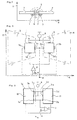
- FIG. 1 which is not true to scale, shows one in cross section in an xy plane Magnetic field sensor, the two horizontal Hall elements 1, 2 and two magnetic flux concentrators 3 and 4 for amplifying a magnetic field B having the direction x includes.
- the two flow concentrators 3 and 4 are separated by an air gap 5.
- the Geometric course of the field lines of the magnetic field B in the area of the air gap 5 is with dashed lines 6, 7 shown.
- the two Hall elements 1 and 2 are outside the air gap 5 arranged.
- the geometric dimensions of the flux concentrators 3, 4 and their the distance defining the air gap 5 are chosen so that the proportion of the not directly through the air gap 5 leading field lines 7 compared to the leading through the air gap 5 Field lines 6 is as large as possible.
- Next are the geometric dimensions of the flux concentrators 3, 4 chosen so that saturation effects due to their magnetic Properties with the greatest possible field strength of the magnetic field B at the location of the Hall elements 1, 2 occur.
- the Hall element 1 is flooded by field lines 7, which go away from the first flux concentrator 3 in the vicinity of the air gap 5, the Hall element 2 is flooded by the field lines 7, which impinge on the second flux concentrator 4 in the vicinity of the air gap 5.
- each field line 7 flows through either both or none of the Hall elements 1 and 2. Since the magnetic permeability of the flux concentrators 3, 4 is selected to be at least a factor 10 3 greater than the permeability of air, the field lines 6, 7 leave the flux concentrators 3 , 4 at an approximately perpendicular angle.
- the field lines 7 flowing through the Hall element 1 accordingly point approximately in the negative y direction (FIG. 1) when the magnetic field B is positive, and the field lines 7 flowing through the Hall element 2 point in the positive y direction.
- the dimensions of the flux concentrators 3, 4 in the xz plane are typically a few tenths of a millimeter, the thickness in the xy plane is typically a few 10 micrometers.
- the air gap 5 measures 50 micrometers, for example. This arrangement allows the air gap 5 to be independent of the dimensions of the Hall element.
- FIG. 2 shows the two Hall elements 1, 2 in an xz plane perpendicular to the xy plane conventional design with two voltage electrodes 1a, 1b or 2a, 2b and two Current electrodes 1c, 1d and 2c, 2d, the two flux concentrators 3, 4 and the electrical Wiring of Hall elements 1, 2.
- the Hall elements 1, 2 shown schematically are electrically connected in parallel and from a common current source 8 with a current fed.
- the voltage electrodes 1a and 2b are the Hall elements 1, 2 virtually connected to ground m.
- the other two voltage electrodes 1b and 2a of the two Hall elements 1, 2 are connected to each other and to an output A. led to which the Hall voltage is present.
- the Hall elements 1, 2 are switched so that the individual Hall voltages in the opposite direction to those flowing through them Add field lines 7 ( Figure 1) of the magnetic field.
- the use of two identical, Hall elements 1, 2 connected in parallel also eliminates z. B. by technology-related Systematic offset voltages generated by asymmetries. Through both Hall elements 1, 2 flows a current l of approximately the same strength and the same z-direction.
- Hall elements can also be used in which three or all four electrodes are arranged on one side of the rectangle.
- Such Hall elements are from the European patent EP 362 493 known.
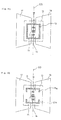
- Figure 3 shows a magnetic field sensor and its electrical wiring with two such Hall elements 10, 11.
- the special on these rectangular Hall elements 10 and 11 is that on one side of the rectangle the three electrodes 1a, 1b and 1c or 2a, 2b and 2c are attached and that the fourth Electrode 1 or 2d along the entire circumference of the three other sides of the rectangle extends.
- the two Hall elements 10, 11 are fused into a single Hall element 12, the two original fourth electrodes 1d and 2d forming a single annular outer electrode 13 and the respectively opposite electrodes 1b and 2a, 1c and 2c and 1a and 2b coincide as inner electrodes 14, 15 and 16.
- the electrodes 13 and 15 serve as current electrodes, the electrodes 14 and 16 as voltage electrodes.
- Hall element 12 can be implemented, for example, in CMOS technology as an n-well in a p-doped subsrate. With a single mask, the electrodes 13 to 16 can be produced as heavily doped n ++ islands which define the effective structure of the Hall element 12. Hall element 12 is therefore characterized by low offset voltages when the geometry and the manufacturing process are carefully selected.
- the Hall element 12 and possibly adjacent surfaces of the chip structured surface parts 17, 18 made of ferromagnetic material, such as Permalloy or Mumetall, coated.
- These surface parts 17, 18 represent flux concentrators represents, technology-related the geometry of the air gap 5 as well as the location of the Air gap 5 very precisely with respect to Hall element 12, i.e. precise to the micrometer, definable is.
- the surface parts 17, 18 have a thickness of a few tenths to a few tens Micrometers and are, for example, by sputtering, vapor deposition and / or galvanic been applied.
- the surface parts 17, 18 are either with the flow concentrators 3, 4 can be combined or they can be standalone flow concentrators.
- the outer electrode 13 is in two electrodes 13a and 13b divided, which are preferably U-shaped and whose side arms extend to about extend to the height of the sensor electrodes 14 and 16, respectively.
- the electrodes 13a and 13b are electrically shorted so that they have a single electrical contact of the Form Hall element 12.
- the electrodes 13a, 14, 15, 16 and 13b are along a fictitious one Straight lines 60 are arranged, which extend along the air gap 5 and perpendicular to the field lines 6 ( Figure 1) of the magnetic field within the air gap 5 extends.
- the stray field is symmetrical with respect the y-axis.
- a further magnetic body 50 which, as in FIGS. 5a and 5b shown below the Hall elements 1, 2 ( Figure 5a) or the Hall element 12 ( Figure 5b) and Is attached symmetrically to the air gap, the Hall elements 1, 2 and that Stray field portion flowing through Hall element 12 in comparison to that directly through the air gap 5 flowing field portion and thus the sensitivity of the magnetic field sensor can be increased.
- the air gaps 51a, 51b formed between the flow concentrators 3, 4 and the body 50 are smaller than the air gap 5, so that the Hall elements 1, 2 and the Hall element 12 magnetic field flowing through in comparison to the magnetic field flowing through the air gap 5 is as large as possible. If the two Hall elements 1, 2 ( Figure 1) on a single chip are included or if the Hall element 12 is used, the back of the Chips or the Hall element 12 coated with ferromagnetic material that the Function of the body 50 takes over.
- FIGS. 6 and 7 show a top view and a cross section of a current sensor 19 which is suitable for measuring comparatively small currents of up to typically 20 A.
- the Current sensor 19 comprises a current conductor 20, a ferromagnetic yoke 21, a lead frame 22, an electronic chip 23 with two horizontal Hall elements 24, 25, one Insulation layer 26 and a plastic housing 27.
- the current conductor 20 is with guide holes 28 provided for self-adjusting production. To increase the magnetic field strength the current conductor 20 is formed in the region of the Hall elements 24, 25 with a taper 29.
- the current conductor 20 also has two holes 30 outside the housing 27, which with Terminals for an electrical conductor are provided, whose current with the Current sensor 19 is to be measured.
- the lead frame is formed with connecting legs 31 which serve the electrical contacting of the chip 23.
- the yoke 21 encloses the current conductor 20 on three sides. On the fourth side of the current conductor 20 are the Insulation layer 26 and the chip 23.
- the Hall elements 24, 25 are on the chip 23 placed according to the dimensions of the current conductor 20 and the yoke 21 so that they are in the range of the maximum strength of the magnetic field B, which is from the Current conductor 20 flowing current I is generated.
- the current sensor 19 is in conventional IC technology. It has the form of an integrated module a plastic case, next to the ones that look like ordinary pins Legs 31 two parts of the plastic housing protruding 27 Current conductor 20 are provided for the direct connection of lead wires.
- the thickness of the conductor 20 is typically a few tenths of a millimeter or a whole Millimeter.
- heat is generated during operation of the current sensor 19 the unrejuvenated part is to be led outside and to the surroundings, so that the Current sensor 19 is not heated above a temperature destroying it.
- the current conductor 20 can also be designed as a lead frame, so that the current sensor 19 with that from the Production of power transistors known 2-leadframe technology can be produced.
- heat sinks connected to the current conductor 20 can be connected to the housing 27 be provided so that the tapered part 29 are kept very narrow and the maximum permitted current in the current conductor 20 generated heat can still be dissipated can without damaging the current sensor 19.
- the yoke 21 advantageously consists of a nickel-iron alloy, e.g. made of Mumetal or Permalloy.
- the current conductor 20 is preferably made of copper.
- the current sensor 19 is insensitive to external magnetic interference fields since the first Hall element 24 and the second Hall element 25 such an interference field with the reverse Record the sign, since they each supply a positive Hall voltage when they flow through them magnetic fields have a different direction. Thanks to this Such a current sensor 19 is particularly suitable for being insensitive to interference fields Measurement of smallest currents.
- the yoke 21 is omitted and the both Hall elements 24 and 25 are replaced by a single Hall element like that in the Figure 5b shown.
- the Hall element can be provided with the flux concentrators or not.
- the dimensions of the current conductor 19 are based on the geometry of the Hall element and possibly the flow concentrators matched.
- Figures 8 and 9 show in plan view and in cross section a larger one for measurement Current sensor 40.
- the current sensor 40 consists of three separately producible parts: a current conductor 41, a ferromagnetic yoke 42 and one Magnetic field sensor 43.
- the magnetic field sensor 43 is of the type of e.g. in Figure 1 shown magnetic field sensor 1. It has the shape of an IC chip, in the next the Hall elements 1, 2 (FIG. 2) and the Hall element 12 (FIG. 4a, FIG. 4b) also the Flow concentrators 3, 4 are integrated.
- the yoke 42 encloses the rectangular one Current conductor 41 on three sides, while the fourth side is covered by the magnetic field sensor 43.
- the yoke 42 is preferably formed with laterally extending feet 44 and with the Magnetic field sensor 43 glued.
- the yoke 42 and those present in the magnetic field sensor 43 Flux concentrators 3, 4 are matched to each other because they have a magnetic circuit form, which leads the magnetic field generated by the current flowing in the conductor 41.
- Flux concentrators 3, 4 are matched to each other because they have a magnetic circuit form, which leads the magnetic field generated by the current flowing in the conductor 41.
- the two air gaps between the yoke 42 and the flux concentrators 3 and 4 respectively dimensioned as small as possible.
- the current sensors 19 and 40 can with the same geometric structure and Corresponding electrical adaptation can also be designed as energy sensors.
Description
Die Flusskonzentratoren sind gegen das Hallelement hin verjüngt ausgebildet, um im Luftspalt in Bezug auf den im Leiter fliessenden Strom ein möglichst hohes Magnetfeld und damit eine hohe Empfindlichkeit zu erreichen. Die Geometrie der Flusskonzentratoren ist dahingehend optimiert, dass der magnetische Fluss ausserhalb des Luftspaltes, d.h. der Streufeldanteil, möglichst gering ist, so dass die Linearität des Magnetfeldsensors nicht durch Sättigungseffekte der Flusskonzentratoren beeinträchtigt ist. Die minimal mögliche Breite des Luftspaltes ist durch die Abmessungen des sich darin befindenden Hallelementes nach unten begrenzt.
- Figur 1
- einen Magnetfeldsensor im Querschnitt,
- Figur 2
- den Magnetfeldsensor in einer ersten Ausführung mit zwei Hallelementen in der Draufsicht,
- Figur 3
- den mit zwei speziellen Hallelementen versehenen Magnetfeldsenor,
- Figur 4a, 4b
- den Magnetfeldsensor in einer zweiten Ausführung mit einem einzigen Hallelement in der Draufsicht,
- Figur 5a, 5b
- weitere Magnetfeldsensoren,
- Figur 6
- einen Stromsensor in der Draufsicht,
- Figur 7
- den Stromsensor im Querschnitt,
- Figur 8
- einen weiteren Stromsensor in der Draufsicht und
- Figur 9
- den weiteren Stromsensor im Querschnitt.
Claims (7)
- Magnetfeldsensor, der zwei Flusskonzentratoren (3, 4) und einen Sensor zur Messung eines Magnetfeldes aufweist, wobei die Flusskonzentratoren (3, 4) durch einen Luftspalt (5) getrennt sind, dadurch gekennzeichnet, dass als Sensor zwei Hallelemente (1, 2) dienen, dass die Hallelemente (1, 2) ausserhalb des Luftspaltes (5) und auf entgegengesetzten Seiten des Luftspaltes (5) in einer parallel zur Ebene der Flusskonzentratoren (3, 4) verlaufenden Ebene angeordnet sind und dass die Hallelemente (1, 2) von Feldlinien (7) des Magnetfeldes durchflutet sind, die vom ersten Flusskonzentrator (3) in der Nähe des Luftspaltes (5) weggehen und in der Nähe des Luftspaltes (5) auf den zweiten Flusskonzentrator (4) auftreffen.
- Magnetfeldsensor nach Anspruch 1, dadurch gekennzeichnet, dass in einer parallel zur Ebene der Flusskonzentratoren (3, 4) verlaufenden Ebene ein Körper (50) aus einem magnetischen Material so angeordnet ist, dass zwischen dem ersten Flusskonzentrator (3) und dem Körper (50) und dass zwischen dem zweiten Flusskonzentrator (4) und dem Körper (50) je ein Luftspalt (51a; 51b) gebildet ist, dass diese Luftspalte (51a; 51b) kleiner als der direkte Luftspalt (5) zwischen den Ftusskonzentratoren (3, 4) sind und dass das erste Hallelement (1) und das zweite Hallelement (2) in diesen Luftspalten (51a; 51b) angeordnet sind.
- Magnetfeldsensor, der zwei Flusskonzentratoren (3, 4) und ein Hallelement (12) zur Messung eines Magnetfeldes aufweist, wobei die Flusskonzentratoren (3, 4) durch einen Luftspalt (5) getrennt sind, dadurch gekennzeichnet, dass das Hallelement (12) ausserhalb des Luftspaltes (5) angeordnet ist und dass ein Teil der vom ersten Flusskonzentrator (3) zum zweiten Flusskonzentrator (4) führenden Feldlinien (7) des Magnetfeldes das Hallelement (12) in annähernd entgegengesetzten Richtungen durchflutet.
- Magnetfeldsensor nach Anspruch 3, dadurch gekennzeichnet, dass die Strom- und Spannungselektroden (13, 14, 15, 16; 13a, 14, 15,16, 13b) des Hallelementes (12) entlang einer fiktiven Geraden (60) angeordnet sind, wobei sich diese Gerade (60) annähernd senkrecht zu den innerhalb des Luftspaltes (5) verlaufenden Feldlinien (6) des Magnetfeldes erstreckt.
- Strom- oder Energiesensor (19) mit einem Magnetfeldsensor nach einem der Ansprüche 1 bis 4, dadurch gekennzeichnet, dass der Strom- bzw. Energiesensor (19) einen Stromleiter (20) mit einer Verjüngung (29) aufweist, dass ein magnetisches Joch (21) den Stromleiter (20) auf drei Seiten umschliesst, dass auf der vierten Seite des Stromleiters (20) der Magnetfeldsensor angeordnet ist und dass Teile des Stromleiters (20), das Joch (21) und der Magnetfeldsensor in ein Kunststoffgehäuse (27) vergossen sind.
- Strom- oder Energiesensor (19) mit einem Magnetfeldsensor nach einem der Ansprüche 1 bis 4, dadurch gekennzeichnet, dass der Strom- bzw. Energiesensor (19) einen Stromleiter (20) mit einer Verjüngung (29) aufweist, dass auf der einen Seite des Stromleiters (20) der Magnetfeldsensor angeordnet ist und dass Teile des Stromleiters (20) und der Magnetfeldsensor in ein Kunststoffgehäuse (27) vergossen sind.
- Strom- oder Energiesensor (40) mit einem Magnetfeldsensor nach einem der Ansprüche 1 bis 4, dadurch gekennzeichnet, dass der Magnetfeldsensor in einem Kunststoffgehäuse (43) vergossen ist, dass das Kunststoffgehäuse (43) und ein magnetisches Joch (42) einen Stromleiter (41) zusammen vollständig umschliessen und dass das Joch (42) und die Flusskonzentratoren (3, 4) des Magnetfeldsensors einen magnetischen Kreis zur Führung des Magnetfeldes bilden, das von dem im Stromleiter (41) fliessenden Strom erzeugt wird.
Applications Claiming Priority (4)
| Application Number | Priority Date | Filing Date | Title |
|---|---|---|---|
| CH306295 | 1995-10-30 | ||
| CH3062/95 | 1995-10-30 | ||
| CH306295 | 1995-10-30 | ||
| US08/734,948 US5942895A (en) | 1995-10-30 | 1996-10-23 | Magnetic field sensor and current and/or energy sensor |
Publications (3)
| Publication Number | Publication Date |
|---|---|
| EP0772046A2 EP0772046A2 (de) | 1997-05-07 |
| EP0772046A3 EP0772046A3 (de) | 1998-02-18 |
| EP0772046B1 true EP0772046B1 (de) | 2002-04-17 |
Family
ID=25692077
Family Applications (1)
| Application Number | Title | Priority Date | Filing Date |
|---|---|---|---|
| EP96116868A Expired - Lifetime EP0772046B1 (de) | 1995-10-30 | 1996-10-21 | Magnetfeldsensor und Strom- oder Energiesensor |
Country Status (2)
| Country | Link |
|---|---|
| US (1) | US6184679B1 (de) |
| EP (1) | EP0772046B1 (de) |
Cited By (1)
| Publication number | Priority date | Publication date | Assignee | Title |
|---|---|---|---|---|
| US9559293B2 (en) | 2007-12-04 | 2017-01-31 | Infineon Technologies Ag | Integrated circuit including sensor having injection molded magnetic material |
Families Citing this family (137)
| Publication number | Priority date | Publication date | Assignee | Title |
|---|---|---|---|---|
| US5910854A (en) | 1993-02-26 | 1999-06-08 | Donnelly Corporation | Electrochromic polymeric solid films, manufacturing electrochromic devices using such solid films, and processes for making such solid films and devices |
| US5668663A (en) | 1994-05-05 | 1997-09-16 | Donnelly Corporation | Electrochromic mirrors and devices |
| US6891563B2 (en) | 1996-05-22 | 2005-05-10 | Donnelly Corporation | Vehicular vision system |
| US6326613B1 (en) | 1998-01-07 | 2001-12-04 | Donnelly Corporation | Vehicle interior mirror assembly adapted for containing a rain sensor |
| US6124886A (en) | 1997-08-25 | 2000-09-26 | Donnelly Corporation | Modular rearview mirror assembly |
| US6172613B1 (en) | 1998-02-18 | 2001-01-09 | Donnelly Corporation | Rearview mirror assembly incorporating vehicle information display |
| US8294975B2 (en) | 1997-08-25 | 2012-10-23 | Donnelly Corporation | Automotive rearview mirror assembly |
| WO1999014605A1 (en) * | 1997-09-15 | 1999-03-25 | Institute Of Quantum Electronics | A current monitor system and a method for manufacturing it |
| US6445287B1 (en) | 2000-02-28 | 2002-09-03 | Donnelly Corporation | Tire inflation assistance monitoring system |
| US8288711B2 (en) | 1998-01-07 | 2012-10-16 | Donnelly Corporation | Interior rearview mirror system with forwardly-viewing camera and a control |
| DE59912726D1 (de) * | 1998-03-30 | 2005-12-08 | Sentron Ag Zug | Magnetfeldsensor |
| US6693517B2 (en) | 2000-04-21 | 2004-02-17 | Donnelly Corporation | Vehicle mirror assembly communicating wirelessly with vehicle accessories and occupants |
| US6477464B2 (en) | 2000-03-09 | 2002-11-05 | Donnelly Corporation | Complete mirror-based global-positioning system (GPS) navigation solution |
| US6329925B1 (en) | 1999-11-24 | 2001-12-11 | Donnelly Corporation | Rearview mirror assembly with added feature modular display |
| EP1031844A3 (de) * | 1999-02-25 | 2009-03-11 | Liaisons Electroniques-Mecaniques Lem S.A. | Verfahren zur Herstellung eines elektrischen Stromsensors |
| EP1050855A1 (de) | 1999-05-06 | 2000-11-08 | Ascom AG | Vorrichtung zum Detektieren einer magnetischen Kennung eines Prüfobjektes |
| WO2007053710A2 (en) | 2005-11-01 | 2007-05-10 | Donnelly Corporation | Interior rearview mirror with display |
| EP1263626A2 (de) | 2000-03-02 | 2002-12-11 | Donnelly Corporation | Video-spiegelsystem mit zusatzmodul |
| US7370983B2 (en) | 2000-03-02 | 2008-05-13 | Donnelly Corporation | Interior mirror assembly with display |
| US7167796B2 (en) | 2000-03-09 | 2007-01-23 | Donnelly Corporation | Vehicle navigation system for use with a telematics system |
| JP4936299B2 (ja) † | 2000-08-21 | 2012-05-23 | メレクシス・テクノロジーズ・ナムローゼフェンノートシャップ | 磁場方向検出センサ |
| ATE363413T1 (de) | 2001-01-23 | 2007-06-15 | Donnelly Corp | Verbessertes fahrzeugbeleuchtungssystem |
| US7581859B2 (en) | 2005-09-14 | 2009-09-01 | Donnelly Corp. | Display device for exterior rearview mirror |
| US7255451B2 (en) | 2002-09-20 | 2007-08-14 | Donnelly Corporation | Electro-optic mirror cell |
| JP4164626B2 (ja) * | 2001-06-15 | 2008-10-15 | サンケン電気株式会社 | ホ−ル素子を備えた電流検出装置 |
| EP1267173A3 (de) * | 2001-06-15 | 2005-03-23 | Sanken Electric Co., Ltd. | Hall-Effektstromdetektor |
| EP1273921A1 (de) * | 2001-07-06 | 2003-01-08 | Sanken Electric Co., Ltd. | Hall-Effekt-Stromdetektor |
| EP1281974B1 (de) * | 2001-07-06 | 2007-04-18 | Sanken Electric Co., Ltd. | Hall-Effekt-Stromdetektor |
| DE02775480T1 (de) | 2001-11-01 | 2005-08-18 | Sentron Ag | Stromsensor und stromsensor herstellungsverfahren |
| US20030111999A1 (en) * | 2001-12-19 | 2003-06-19 | Ertugrul Berkcan | Residential electricity meter |
| EP1498697A4 (de) | 2002-03-22 | 2011-06-29 | Melexis Tessenderlo Nv | Winkelbestimmungsvorrichtung und winkelbestimmungssystem |
| DE10392295T5 (de) * | 2002-04-04 | 2005-05-19 | Hitachi, Ltd. | Stromrichter und damit ausgestatteter Elektroantrieb und damit ausgestattete mobile Vorrichtung |
| US6918674B2 (en) | 2002-05-03 | 2005-07-19 | Donnelly Corporation | Vehicle rearview mirror system |
| WO2003105099A1 (en) | 2002-06-06 | 2003-12-18 | Donnelly Corporation | Interior rearview mirror system with compass |
| US7329013B2 (en) | 2002-06-06 | 2008-02-12 | Donnelly Corporation | Interior rearview mirror system with compass |
| US7310177B2 (en) | 2002-09-20 | 2007-12-18 | Donnelly Corporation | Electro-optic reflective element assembly |
| WO2004103772A2 (en) | 2003-05-19 | 2004-12-02 | Donnelly Corporation | Mirror assembly for vehicle |
| AU2003278863A1 (en) | 2002-09-20 | 2004-04-08 | Donnelly Corporation | Mirror reflective element assembly |
| US6831458B2 (en) * | 2002-10-21 | 2004-12-14 | Honeywell International Inc. | Magnetic differential field sensor using hysteresis field in AMR films |
| US20040251506A1 (en) * | 2003-06-10 | 2004-12-16 | Johnson Mark B. | Hall effect devices, memory devices, and hall effect device readout voltage increasing methods |
| US7446924B2 (en) | 2003-10-02 | 2008-11-04 | Donnelly Corporation | Mirror reflective element assembly including electronic component |
| US7308341B2 (en) | 2003-10-14 | 2007-12-11 | Donnelly Corporation | Vehicle communication system |
| US7095193B2 (en) * | 2004-05-19 | 2006-08-22 | Hr Textron, Inc. | Brushless DC motors with remote Hall sensing and methods of making the same |
| US7205757B2 (en) * | 2004-09-02 | 2007-04-17 | Denso Corporation | High precision current sensor |
| DE102004047784A1 (de) * | 2004-10-01 | 2006-04-06 | Robert Bosch Gmbh | Sensor zur Detektion der Richtung eines Magnetfeldes |
| US7476953B2 (en) * | 2005-02-04 | 2009-01-13 | Allegro Microsystems, Inc. | Integrated sensor having a magnetic flux concentrator |
| ATE517368T1 (de) | 2005-05-16 | 2011-08-15 | Donnelly Corp | Fahrzeugspiegelanordnung mit zeichen am reflektierenden teil |
| JP2007003237A (ja) * | 2005-06-21 | 2007-01-11 | Denso Corp | 電流センサ |
| EP1746426B1 (de) | 2005-07-22 | 2019-03-06 | Melexis Technologies NV | Stromsensor |
| JP4415923B2 (ja) * | 2005-09-30 | 2010-02-17 | Tdk株式会社 | 電流センサ |
| EP1772737A3 (de) * | 2005-10-08 | 2008-02-20 | Melexis Technologies SA | Baugruppe zur Strommessung |
| US20070167741A1 (en) * | 2005-12-30 | 2007-07-19 | Sherman Jason T | Apparatus and method for registering a bone of a patient with a computer assisted orthopaedic surgery system |
| US20070161888A1 (en) * | 2005-12-30 | 2007-07-12 | Sherman Jason T | System and method for registering a bone of a patient with a computer assisted orthopaedic surgery system |
| US7525309B2 (en) | 2005-12-30 | 2009-04-28 | Depuy Products, Inc. | Magnetic sensor array |
| US8862200B2 (en) * | 2005-12-30 | 2014-10-14 | DePuy Synthes Products, LLC | Method for determining a position of a magnetic source |
| EP1811311B1 (de) * | 2006-01-19 | 2016-08-31 | Melexis Technologies NV | Vorrichtung zur Strommessung |
| US7768083B2 (en) | 2006-01-20 | 2010-08-03 | Allegro Microsystems, Inc. | Arrangements for an integrated sensor |
| RS20060511A (en) * | 2006-09-06 | 2008-11-28 | Ametes Ag., | Sensor and procedure for measuring bus bar current with skin effect correction |
| US8068648B2 (en) * | 2006-12-21 | 2011-11-29 | Depuy Products, Inc. | Method and system for registering a bone of a patient with a computer assisted orthopaedic surgery system |
| FR2911690B1 (fr) * | 2007-01-19 | 2009-03-06 | Thales Sa | Dispositif d'amplification magnetique comportant un capteur magnetique a sensibilite longitudinale |
| US8013780B2 (en) | 2007-01-25 | 2011-09-06 | Magna Electronics Inc. | Radar sensing system for vehicle |
| US7816772B2 (en) * | 2007-03-29 | 2010-10-19 | Allegro Microsystems, Inc. | Methods and apparatus for multi-stage molding of integrated circuit package |
| DE102007062633B4 (de) * | 2007-12-22 | 2010-04-15 | Sensitec Gmbh | Anordnung zum potentialfreien Messen von Strömen |
| US9823090B2 (en) | 2014-10-31 | 2017-11-21 | Allegro Microsystems, Llc | Magnetic field sensor for sensing a movement of a target object |
| US8154418B2 (en) | 2008-03-31 | 2012-04-10 | Magna Mirrors Of America, Inc. | Interior rearview mirror system |
| AT506682B1 (de) * | 2008-04-17 | 2014-05-15 | Adaptive Regelsysteme Ges M B H | Strommesseinrichtung und verfahren zur galvanisch getrennten messung von strömen |
| US7816905B2 (en) * | 2008-06-02 | 2010-10-19 | Allegro Microsystems, Inc. | Arrangements for a current sensing circuit and integrated current sensor |
| US9487144B2 (en) | 2008-10-16 | 2016-11-08 | Magna Mirrors Of America, Inc. | Interior mirror assembly with display |
| FR2937722B1 (fr) * | 2008-10-24 | 2010-11-26 | Moving Magnet Tech Mmt | Capteur de position magnetique a mesure de direction de champ et a collecteur de flux |
| ATE552510T1 (de) * | 2008-12-03 | 2012-04-15 | St Microelectronics Srl | Magnetischer sensor mit grossem messbereich und herstellungsprozess für den sensor |
| US8486755B2 (en) * | 2008-12-05 | 2013-07-16 | Allegro Microsystems, Llc | Magnetic field sensors and methods for fabricating the magnetic field sensors |
| US20100188078A1 (en) * | 2009-01-28 | 2010-07-29 | Andrea Foletto | Magnetic sensor with concentrator for increased sensing range |
| JP5680287B2 (ja) * | 2009-05-27 | 2015-03-04 | 新科實業有限公司SAE Magnetics(H.K.)Ltd. | 電流センサ |
| JP5027191B2 (ja) * | 2009-07-31 | 2012-09-19 | 株式会社鷺宮製作所 | 圧力センサ及びその調整方法 |
| WO2012051500A1 (en) | 2010-10-15 | 2012-04-19 | Magna Mirrors Of America, Inc. | Interior rearview mirror assembly |
| US10107875B2 (en) * | 2009-11-30 | 2018-10-23 | Infineon Technologies Ag | GMR sensor within molded magnetic material employing non-magnetic spacer |
| DE102010050356B4 (de) * | 2010-05-20 | 2016-04-21 | Walter Mehnert | Magnetfeldsensor |
| RU2453853C2 (ru) * | 2010-09-27 | 2012-06-20 | Федеральное Государственное Унитарное Предприятие "Государственный научно-производственный ракетно-космический центр "ЦСКБ-Прогресс" (ФГУП "ГНПРКЦ "ЦСКБ-Прогресс") | Способ измерения силы тока в проводнике и устройство для его осуществления |
| CH703903B1 (de) * | 2010-10-01 | 2014-04-30 | Melexis Tessenderlo Nv | Stromsensor. |
| CH705027A1 (de) | 2011-05-30 | 2012-11-30 | Melexis Technologies Nv | Vorrichtung zur Messung eines durch ein elektrisches Kabel fliessenden Stroms. |
| BE1020034A3 (nl) | 2011-06-27 | 2013-04-02 | Psi Control Mechatronics | Inrichting voor het detecteren van een stroom, een voertuig en een werkwijze. |
| US9103868B2 (en) | 2011-09-15 | 2015-08-11 | Infineon Technologies Ag | Vertical hall sensors |
| DE102012216388A1 (de) | 2011-09-16 | 2013-03-21 | Infineon Technologies Ag | Hall-sensoren mit erfassungsknoten mit signaleinprägung |
| US8922207B2 (en) | 2011-11-17 | 2014-12-30 | Infineon Technologies Ag | Electronic device comprising hall effect region with three contacts |
| US8629539B2 (en) | 2012-01-16 | 2014-01-14 | Allegro Microsystems, Llc | Methods and apparatus for magnetic sensor having non-conductive die paddle |
| US9812588B2 (en) | 2012-03-20 | 2017-11-07 | Allegro Microsystems, Llc | Magnetic field sensor integrated circuit with integral ferromagnetic material |
| US9494660B2 (en) | 2012-03-20 | 2016-11-15 | Allegro Microsystems, Llc | Integrated circuit package having a split lead frame |
| US10234513B2 (en) | 2012-03-20 | 2019-03-19 | Allegro Microsystems, Llc | Magnetic field sensor integrated circuit with integral ferromagnetic material |
| US9666788B2 (en) | 2012-03-20 | 2017-05-30 | Allegro Microsystems, Llc | Integrated circuit package having a split lead frame |
| JP6256819B2 (ja) * | 2012-03-29 | 2018-01-10 | マレクシス テクノロジーズ エヌヴィー | 電流センサ及び電流測定装置 |
| US10215550B2 (en) | 2012-05-01 | 2019-02-26 | Allegro Microsystems, Llc | Methods and apparatus for magnetic sensors having highly uniform magnetic fields |
| US9817078B2 (en) | 2012-05-10 | 2017-11-14 | Allegro Microsystems Llc | Methods and apparatus for magnetic sensor having integrated coil |
| US9018948B2 (en) | 2012-07-26 | 2015-04-28 | Infineon Technologies Ag | Hall sensors and sensing methods |
| US9170307B2 (en) | 2012-09-26 | 2015-10-27 | Infineon Technologies Ag | Hall sensors and sensing methods |
| CH707687B1 (de) * | 2013-03-08 | 2016-09-15 | Melexis Technologies Nv | Stromsensor. |
| US10725100B2 (en) | 2013-03-15 | 2020-07-28 | Allegro Microsystems, Llc | Methods and apparatus for magnetic sensor having an externally accessible coil |
| US9411025B2 (en) | 2013-04-26 | 2016-08-09 | Allegro Microsystems, Llc | Integrated circuit package having a split lead frame and a magnet |
| CH708052B1 (de) | 2013-05-07 | 2016-09-15 | Melexis Technologies Nv | Vorrichtung zur Strommessung. |
| CN103439749A (zh) * | 2013-07-10 | 2013-12-11 | 中北大学 | 一种应用于微型磁传感器的磁集聚放大导向结构 |
| US10145908B2 (en) | 2013-07-19 | 2018-12-04 | Allegro Microsystems, Llc | Method and apparatus for magnetic sensor producing a changing magnetic field |
| US9810519B2 (en) | 2013-07-19 | 2017-11-07 | Allegro Microsystems, Llc | Arrangements for magnetic field sensors that act as tooth detectors |
| US10495699B2 (en) | 2013-07-19 | 2019-12-03 | Allegro Microsystems, Llc | Methods and apparatus for magnetic sensor having an integrated coil or magnet to detect a non-ferromagnetic target |
| US9316705B2 (en) | 2014-05-09 | 2016-04-19 | Infineon Technologies Ag | Vertical hall effect-device |
| US9425385B2 (en) | 2014-05-09 | 2016-08-23 | Infineon Technologies Ag | Vertical hall effect device |
| US10712403B2 (en) | 2014-10-31 | 2020-07-14 | Allegro Microsystems, Llc | Magnetic field sensor and electronic circuit that pass amplifier current through a magnetoresistance element |
| US9823092B2 (en) | 2014-10-31 | 2017-11-21 | Allegro Microsystems, Llc | Magnetic field sensor providing a movement detector |
| US9720054B2 (en) | 2014-10-31 | 2017-08-01 | Allegro Microsystems, Llc | Magnetic field sensor and electronic circuit that pass amplifier current through a magnetoresistance element |
| US9719806B2 (en) | 2014-10-31 | 2017-08-01 | Allegro Microsystems, Llc | Magnetic field sensor for sensing a movement of a ferromagnetic target object |
| EP3093672B1 (de) * | 2015-05-09 | 2020-08-12 | LEM International SA | Stromwandler mit integrierter primärer leiterschiene |
| CH712525A1 (de) | 2016-06-06 | 2017-12-15 | Melexis Tech Sa | Magnetfeldsensor mit integrierten Magnetfeldkonzentratoren. |
| US10260905B2 (en) | 2016-06-08 | 2019-04-16 | Allegro Microsystems, Llc | Arrangements for magnetic field sensors to cancel offset variations |
| US10041810B2 (en) | 2016-06-08 | 2018-08-07 | Allegro Microsystems, Llc | Arrangements for magnetic field sensors that act as movement detectors |
| US10012518B2 (en) | 2016-06-08 | 2018-07-03 | Allegro Microsystems, Llc | Magnetic field sensor for sensing a proximity of an object |
| JP2018013391A (ja) | 2016-07-20 | 2018-01-25 | メレキシス テクノロジーズ エス エー | 変位検出装置 |
| US10324141B2 (en) | 2017-05-26 | 2019-06-18 | Allegro Microsystems, Llc | Packages for coil actuated position sensors |
| US10837943B2 (en) | 2017-05-26 | 2020-11-17 | Allegro Microsystems, Llc | Magnetic field sensor with error calculation |
| US11428755B2 (en) | 2017-05-26 | 2022-08-30 | Allegro Microsystems, Llc | Coil actuated sensor with sensitivity detection |
| US10996289B2 (en) | 2017-05-26 | 2021-05-04 | Allegro Microsystems, Llc | Coil actuated position sensor with reflected magnetic field |
| US10310028B2 (en) | 2017-05-26 | 2019-06-04 | Allegro Microsystems, Llc | Coil actuated pressure sensor |
| US10641842B2 (en) | 2017-05-26 | 2020-05-05 | Allegro Microsystems, Llc | Targets for coil actuated position sensors |
| US10866117B2 (en) | 2018-03-01 | 2020-12-15 | Allegro Microsystems, Llc | Magnetic field influence during rotation movement of magnetic target |
| US11255700B2 (en) | 2018-08-06 | 2022-02-22 | Allegro Microsystems, Llc | Magnetic field sensor |
| US10921391B2 (en) | 2018-08-06 | 2021-02-16 | Allegro Microsystems, Llc | Magnetic field sensor with spacer |
| US10935612B2 (en) | 2018-08-20 | 2021-03-02 | Allegro Microsystems, Llc | Current sensor having multiple sensitivity ranges |
| US10823586B2 (en) | 2018-12-26 | 2020-11-03 | Allegro Microsystems, Llc | Magnetic field sensor having unequally spaced magnetic field sensing elements |
| US11061084B2 (en) | 2019-03-07 | 2021-07-13 | Allegro Microsystems, Llc | Coil actuated pressure sensor and deflectable substrate |
| US10955306B2 (en) | 2019-04-22 | 2021-03-23 | Allegro Microsystems, Llc | Coil actuated pressure sensor and deformable substrate |
| DE102019207499A1 (de) * | 2019-05-22 | 2020-11-26 | Zf Friedrichshafen Ag | Wechselrichter für einen elektrifizierten Antriebsstrang |
| US10991644B2 (en) | 2019-08-22 | 2021-04-27 | Allegro Microsystems, Llc | Integrated circuit package having a low profile |
| US11237020B2 (en) | 2019-11-14 | 2022-02-01 | Allegro Microsystems, Llc | Magnetic field sensor having two rows of magnetic field sensing elements for measuring an angle of rotation of a magnet |
| US11280637B2 (en) | 2019-11-14 | 2022-03-22 | Allegro Microsystems, Llc | High performance magnetic angle sensor |
| DE102019132593B4 (de) * | 2019-12-02 | 2021-07-22 | Schaeffler Technologies AG & Co. KG | Stromsensor |
| US11262422B2 (en) | 2020-05-08 | 2022-03-01 | Allegro Microsystems, Llc | Stray-field-immune coil-activated position sensor |
| EP3992652A1 (de) * | 2020-11-03 | 2022-05-04 | Melexis Technologies SA | Magnetsensorvorrichtung |
| US11493361B2 (en) | 2021-02-26 | 2022-11-08 | Allegro Microsystems, Llc | Stray field immune coil-activated sensor |
| US11567108B2 (en) | 2021-03-31 | 2023-01-31 | Allegro Microsystems, Llc | Multi-gain channels for multi-range sensor |
| US11578997B1 (en) | 2021-08-24 | 2023-02-14 | Allegro Microsystems, Llc | Angle sensor using eddy currents |
Family Cites Families (12)
| Publication number | Priority date | Publication date | Assignee | Title |
|---|---|---|---|---|
| DE1170537B (de) * | 1955-07-14 | 1964-05-21 | Siemens Ag | Strommessgeraet unter Ausnutzung des Halleffekts |
| JPS5145426B1 (de) * | 1971-05-12 | 1976-12-03 | ||
| GB2154744B (en) * | 1984-02-25 | 1987-10-07 | Standard Telephones Cables Ltd | Magnetic field sensor |
| CH670004A5 (de) * | 1986-02-10 | 1989-04-28 | Landis & Gyr Ag | |
| US4765345A (en) * | 1987-02-18 | 1988-08-23 | Myo-Tronics Research, Inc. | Magnetic sensor for jaw tracking device |
| US5041780A (en) * | 1988-09-13 | 1991-08-20 | California Institute Of Technology | Integrable current sensors |
| ATE96248T1 (de) | 1988-09-21 | 1993-11-15 | Landis & Gyr Business Support | Hallelement. |
| EP0537419A1 (de) * | 1991-10-09 | 1993-04-21 | Landis & Gyr Business Support AG | Anordnung mit einem integrierten Magnetfeldsensor sowie einem ferromagnetischen ersten und zweiten Magnetfluss-Konzentrator und Verfahren zum Einbau einer Vielzahl von Anordnungen in je einem Kunststoffgehäuse |
| EP0595553B1 (de) * | 1992-10-29 | 1996-12-27 | Rolls-Royce And Associates Limited | Verbesserung in Weggebern |
| US5483161A (en) * | 1992-12-11 | 1996-01-09 | The United States Of America As Represented By The Secretary Of Commerce | Faraday effect continuous circuit flux concentrating magnetic field sensor |
| US5719496A (en) * | 1995-06-07 | 1998-02-17 | Durakool Incorporated | Dual-element proximity sensor for sensing the direction of rotation of a ferrous target wheel |
| US5874848A (en) * | 1997-07-09 | 1999-02-23 | Bell Technologies, Inc. | Electric current sensor utilizing a compensating trace configuration |
-
1996
- 1996-10-21 EP EP96116868A patent/EP0772046B1/de not_active Expired - Lifetime
-
1999
- 1999-05-10 US US09/307,694 patent/US6184679B1/en not_active Expired - Lifetime
Cited By (1)
| Publication number | Priority date | Publication date | Assignee | Title |
|---|---|---|---|---|
| US9559293B2 (en) | 2007-12-04 | 2017-01-31 | Infineon Technologies Ag | Integrated circuit including sensor having injection molded magnetic material |
Also Published As
| Publication number | Publication date |
|---|---|
| EP0772046A2 (de) | 1997-05-07 |
| EP0772046A3 (de) | 1998-02-18 |
| US6184679B1 (en) | 2001-02-06 |
Similar Documents
| Publication | Publication Date | Title |
|---|---|---|
| EP0772046B1 (de) | Magnetfeldsensor und Strom- oder Energiesensor | |
| DE10392748B4 (de) | Strommessverfahren und Strommessvorrichtung | |
| DE102005047414B4 (de) | Magnetoresistives Sensormodul und Verfahren zum Herstellen desselben | |
| DE102009054892B4 (de) | Magnetfeldstromsensoren und Verfahren | |
| EP1395844B1 (de) | Magnetfeldsensor | |
| DE102008039568B4 (de) | Stromerfassungsvorrichtung | |
| DE112013005763B4 (de) | Stromsensor und Verfahren zum Herstellen von Stromsensor | |
| EP1110094B1 (de) | Vorrichtung und verfahren zur bildung eines oder mehrerer magnetfeldgradienten durch einen geraden leiter | |
| DE19744050C2 (de) | Magnetischer Sensor | |
| DE102004010126B4 (de) | Magnetfeldsensor und Verfahren zur Herstellung desselben | |
| DE4031560C2 (de) | Stromsensor mit magnetfeldempfindlichen Bauelementen und Verwendung | |
| DE60027257T2 (de) | Stromdetektor mit einer Hall-Effekt-Anordnung | |
| DE60219561T2 (de) | Hall-Effekt-Stromdetektor | |
| EP2801832B1 (de) | Vorrichtung zur Strommessung | |
| EP1772737A2 (de) | Baugruppe zur Strommessung | |
| DE112015005195T5 (de) | Magnetsensor, Herstellungsverfahren dafür, und ihn verwendender Stromdetektor | |
| DE102005047482A1 (de) | Magnetoresistives Sensormodul und Verfahren zum Herstellen desselben | |
| DE19943128A1 (de) | Hall-Sensoranordnung zur Offset-kompensierten Magnetfeldmessung | |
| EP1746426B1 (de) | Stromsensor | |
| DE102018111011A1 (de) | Magnetfeldsensorvorrichtung | |
| DE10108640A1 (de) | Sensoranordnung zur kontaktlosen Strommessung | |
| DE112018000561T5 (de) | Element-einheit mit magnetoresistivem effekt und vorrichtung mit element-einheit mit magnetoresistivem effekt | |
| DE19903585B4 (de) | Halbleitersensor und Halbleitersensorchip und Halbleitersensorgehäuse | |
| DE102018113005B4 (de) | Magnetischer stromsensor | |
| DE112016006631B4 (de) | Magnetsensor |
Legal Events
| Date | Code | Title | Description |
|---|---|---|---|
| PUAI | Public reference made under article 153(3) epc to a published international application that has entered the european phase |
Free format text: ORIGINAL CODE: 0009012 |
|
| AK | Designated contracting states |
Kind code of ref document: A2 Designated state(s): CH DE FR GB IT LI |
|
| PUAL | Search report despatched |
Free format text: ORIGINAL CODE: 0009013 |
|
| AK | Designated contracting states |
Kind code of ref document: A3 Designated state(s): CH DE FR GB IT LI |
|
| 17P | Request for examination filed |
Effective date: 19980327 |
|
| 17Q | First examination report despatched |
Effective date: 20000919 |
|
| GRAG | Despatch of communication of intention to grant |
Free format text: ORIGINAL CODE: EPIDOS AGRA |
|
| GRAG | Despatch of communication of intention to grant |
Free format text: ORIGINAL CODE: EPIDOS AGRA |
|
| RTI1 | Title (correction) |
Free format text: MAGNETIC FIELD PROBE AND CURRENT OR ENERGY PROBE |
|
| GRAG | Despatch of communication of intention to grant |
Free format text: ORIGINAL CODE: EPIDOS AGRA |
|
| GRAH | Despatch of communication of intention to grant a patent |
Free format text: ORIGINAL CODE: EPIDOS IGRA |
|
| REG | Reference to a national code |
Ref country code: GB Ref legal event code: IF02 |
|
| GRAH | Despatch of communication of intention to grant a patent |
Free format text: ORIGINAL CODE: EPIDOS IGRA |
|
| GRAA | (expected) grant |
Free format text: ORIGINAL CODE: 0009210 |
|
| AK | Designated contracting states |
Kind code of ref document: B1 Designated state(s): CH DE FR GB IT LI |
|
| REG | Reference to a national code |
Ref country code: CH Ref legal event code: EP |
|
| REF | Corresponds to: |
Ref document number: 59609089 Country of ref document: DE Date of ref document: 20020523 |
|
| GBT | Gb: translation of ep patent filed (gb section 77(6)(a)/1977) |
Effective date: 20020710 |
|
| ET | Fr: translation filed | ||
| REG | Reference to a national code |
Ref country code: CH Ref legal event code: NV Representative=s name: PATENTANWALTSBUERO DR. URS FALK |
|
| PLBE | No opposition filed within time limit |
Free format text: ORIGINAL CODE: 0009261 |
|
| STAA | Information on the status of an ep patent application or granted ep patent |
Free format text: STATUS: NO OPPOSITION FILED WITHIN TIME LIMIT |
|
| 26N | No opposition filed |
Effective date: 20030120 |
|
| REG | Reference to a national code |
Ref country code: GB Ref legal event code: 732E |
|
| REG | Reference to a national code |
Ref country code: CH Ref legal event code: PLI Owner name: LEM HOLDINGS SA Free format text: SENTRON AG#BAARERSTRASSE 73#6300 ZUG (CH) -TRANSFER TO- LEM HOLDINGS SA#8 CHEMIN DES AULX#1228 PLAN-LES-QUATES (CH) |
|
| REG | Reference to a national code |
Ref country code: FR Ref legal event code: CL |
|
| REG | Reference to a national code |
Ref country code: CH Ref legal event code: PUE Owner name: MELEXIS TECHNOLOGIES SA Free format text: SENTRON AG#BAARERSTRASSE 73#6300 ZUG (CH) -TRANSFER TO- MELEXIS TECHNOLOGIES SA#CHEMIN DE BUCHAUX 38#2022 BEVAIX (CH) |
|
| REG | Reference to a national code |
Ref country code: GB Ref legal event code: 732E |
|
| REG | Reference to a national code |
Ref country code: FR Ref legal event code: TP |
|
| REG | Reference to a national code |
Ref country code: CH Ref legal event code: PUE Owner name: MELEXIS TESSENDERLO NV Free format text: MELEXIS TECHNOLOGIES SA#CHEMIN DE BUCHAUX 38#2022 BEVAIX (CH) -TRANSFER TO- MELEXIS TESSENDERLO NV#TRANSPORTSTRAAT 1#3980 TESSENDERLO (BE) |
|
| REG | Reference to a national code |
Ref country code: GB Ref legal event code: 732E Free format text: REGISTERED BETWEEN 20100805 AND 20100811 |
|
| REG | Reference to a national code |
Ref country code: FR Ref legal event code: TP |
|
| REG | Reference to a national code |
Ref country code: FR Ref legal event code: PLFP Year of fee payment: 20 |
|
| PGFP | Annual fee paid to national office [announced via postgrant information from national office to epo] |
Ref country code: CH Payment date: 20151130 Year of fee payment: 20 Ref country code: DE Payment date: 20151021 Year of fee payment: 20 Ref country code: IT Payment date: 20151030 Year of fee payment: 20 Ref country code: GB Payment date: 20151022 Year of fee payment: 20 |
|
| PGFP | Annual fee paid to national office [announced via postgrant information from national office to epo] |
Ref country code: FR Payment date: 20151022 Year of fee payment: 20 |
|
| REG | Reference to a national code |
Ref country code: DE Ref legal event code: R071 Ref document number: 59609089 Country of ref document: DE |
|
| REG | Reference to a national code |
Ref country code: CH Ref legal event code: PL |
|
| REG | Reference to a national code |
Ref country code: GB Ref legal event code: PE20 Expiry date: 20161020 |
|
| PG25 | Lapsed in a contracting state [announced via postgrant information from national office to epo] |
Ref country code: GB Free format text: LAPSE BECAUSE OF EXPIRATION OF PROTECTION Effective date: 20161020 |