EP0772147B1 - Optical scanner having enhanced item side coverage - Google Patents
Optical scanner having enhanced item side coverage Download PDFInfo
- Publication number
- EP0772147B1 EP0772147B1 EP96307661A EP96307661A EP0772147B1 EP 0772147 B1 EP0772147 B1 EP 0772147B1 EP 96307661 A EP96307661 A EP 96307661A EP 96307661 A EP96307661 A EP 96307661A EP 0772147 B1 EP0772147 B1 EP 0772147B1
- Authority
- EP
- European Patent Office
- Prior art keywords
- scanning
- scanning system
- beams
- mirrors
- window
- Prior art date
- Legal status (The legal status is an assumption and is not a legal conclusion. Google has not performed a legal analysis and makes no representation as to the accuracy of the status listed.)
- Expired - Lifetime
Links
Images


Classifications
-
- G—PHYSICS
- G06—COMPUTING; CALCULATING OR COUNTING
- G06K—GRAPHICAL DATA READING; PRESENTATION OF DATA; RECORD CARRIERS; HANDLING RECORD CARRIERS
- G06K7/00—Methods or arrangements for sensing record carriers, e.g. for reading patterns
- G06K7/10—Methods or arrangements for sensing record carriers, e.g. for reading patterns by electromagnetic radiation, e.g. optical sensing; by corpuscular radiation
- G06K7/10544—Methods or arrangements for sensing record carriers, e.g. for reading patterns by electromagnetic radiation, e.g. optical sensing; by corpuscular radiation by scanning of the records by radiation in the optical part of the electromagnetic spectrum
- G06K7/10821—Methods or arrangements for sensing record carriers, e.g. for reading patterns by electromagnetic radiation, e.g. optical sensing; by corpuscular radiation by scanning of the records by radiation in the optical part of the electromagnetic spectrum further details of bar or optical code scanning devices
- G06K7/1096—Methods or arrangements for sensing record carriers, e.g. for reading patterns by electromagnetic radiation, e.g. optical sensing; by corpuscular radiation by scanning of the records by radiation in the optical part of the electromagnetic spectrum further details of bar or optical code scanning devices the scanner having more than one scanning window, e.g. two substantially orthogonally placed scanning windows for integration into a check-out counter of a super-market
-
- G—PHYSICS
- G06—COMPUTING; CALCULATING OR COUNTING
- G06K—GRAPHICAL DATA READING; PRESENTATION OF DATA; RECORD CARRIERS; HANDLING RECORD CARRIERS
- G06K7/00—Methods or arrangements for sensing record carriers, e.g. for reading patterns
- G06K7/10—Methods or arrangements for sensing record carriers, e.g. for reading patterns by electromagnetic radiation, e.g. optical sensing; by corpuscular radiation
- G06K7/10544—Methods or arrangements for sensing record carriers, e.g. for reading patterns by electromagnetic radiation, e.g. optical sensing; by corpuscular radiation by scanning of the records by radiation in the optical part of the electromagnetic spectrum
- G06K7/10554—Moving beam scanning
- G06K7/10594—Beam path
- G06K7/10683—Arrangement of fixed elements
- G06K7/10693—Arrangement of fixed elements for omnidirectional scanning
-
- G—PHYSICS
- G06—COMPUTING; CALCULATING OR COUNTING
- G06K—GRAPHICAL DATA READING; PRESENTATION OF DATA; RECORD CARRIERS; HANDLING RECORD CARRIERS
- G06K7/00—Methods or arrangements for sensing record carriers, e.g. for reading patterns
- G06K7/10—Methods or arrangements for sensing record carriers, e.g. for reading patterns by electromagnetic radiation, e.g. optical sensing; by corpuscular radiation
- G06K2007/10504—Data fields affixed to objects or articles
- G06K2007/10514—Randomly orientated data fields
Description
- The present invention relates to optical scanners and more specifically to an optical scanner having enhanced item side coverage.
- U.S. Patent No. 5,229,588 to Detwiler et al. discloses a dual aperture optical scanner which includes horizontal and vertical apertures. The scanning light beams from a single laser diode pass through these apertures to provide coverage for up to four sides of a scanned item: the side facing the vertical aperture (front), the side facing the horizontal aperture (bottom), and the left and right sides.
- While this scanner requires much less item orientation than a single aperture scanner, it is not capable of scanning the top and rear sides of scanning items. It is an object of the invention to provide an optical scanner which is capable of scanning as many as five sides of a typical merchandise item.
- United Kingdom Patent Application GB 2284086 describes a multiple plane scanning system ( Figure 20) which permits scanning of five sides of a typical merchandise item, but this is a complex arrangement having three separate apertures at different angles to one another. It is a further object of the present invention to provide a simplified scanner which is capable of scanning as many as five sides of a typical merchandise item.
- In accordance with the invention there is provided a bar code scanning system comprising a housing having first and second windows arranged generally orthogonally to one another, a laser source, a rotatable mirror polygon, and first, second and third sets of plane pattern mirrors arranged to provide scanning beams which illuminate an object to be scanned with a plurality of intersecting lines, the three sets of pattern mirrors being arranged to provide two groups of scanning beams (I,II) which pass through the first window and a further group of scanning beams (III) which passes through the second window, characterized in that the three groups of scanning beams together illuminate the object from angles corresponding to five of the six sides of a cube.
- Preferably the three groups of scanning beams together illuminate the object from angles corresponding to five of the six codes of a cube.
- The invention will now be described by way of example only with reference to the accompanying drawings, in which:
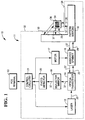
- Fig. 1 is a block diagram of the optical scanner having enhanced item side coverage of the present invention;
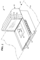
- Fig. 2 is an exterior perspective view of the scanner of the present invention, including a reference coordinate system for the group of pattern mirrors within the scanner of the present invention;
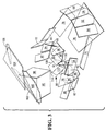
- Fig. 3 is an interior perspective view of the scanner of the present invention;
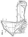
- Fig. 4 is a sectional view of the scanner of the present invention along lines 4-4 of Fig. 3;
- Fig. 5 is a reference coordinate system for determining one-suitable orientation for the group of pattern mirrors within the scanner of the present invention;
- Fig. 6 is a plan view of the scan pattern emanating upwardly from a horizontal aperture;
- Fig. 7 is a plan view of a first scan pattern emanating outwardly from a vertical aperture;
- Fig. 8 is a plan view of a second scan pattern emanating outwardly from the vertical aperture;
- Fig. 9 is a plan view of the combined first and second scan patterns of Figs. 7 and 8; and
- Fig. 10 is a perspective view of a laser assembly showing two lasers.
-
- Referring now to Fig. 1, a point-of-service (POS)
system 10 includesoptical scanner 11 andPOS terminal 13. -
POS terminal 13 receives transaction data, for example, in the form of SKU numbers fromscanner 11 and completes a transaction by finding price data for the SKU numbers in a price-lookup data file. -
Scanner 11 of the present invention includeslaser 12,optical transceiver 14, mirroredspinner 16,pattern mirrors 18,deflector mirror 19,photodetector 20, andcontrol circuit 21. Laser 12 includes a laser diode or other suitable laser source. - A focusing lens or lenses and a collimating aperture are also preferably used to produce a focused and collimated
laser beam 22. In the preferred embodiment, the laser diode emits visible light within a wavelength range of 670-690nm and the collimating aperture and focusing lens produce abeam 22 having a beam waist of 220 microns in the center of the read zone. Other wavelengths and beam waists may be suitably employed. -
Beam 22 passes throughoptical transceiver 14, which includes a mirrored collecting surface and an aperture forpassing beam 22. The mirrored collecting surface preferably has an ellipsoidal or other curved surface. - Beam 22 contacts mirrored
spinner 16, which preferably has four planoreflective mirrored facets 108-114 for producing scanning beams 24 (Fig. 3). Four facets were chosen as an optimal compromise between the increased line length created by using three facets and the increased rastering provided by spinners having more than four facets. -
Scanning beams 24impact pattern mirrors 18, which produce a plurality ofscan lines 26. In the preferred embodiment,pattern mirrors 18 are preferably flat and produce fortyscan lines 26 for each complete revolution of mirroredspinner 16. Advantageously, all fortyscan lines 26 are preferably produced by only onelaser 12 andmotor 17. Use of a greater or lesser number of scan lines and pattern mirrors will be apparent to those skilled in the art. - Some
scan lines 26 pass through a substantiallyhorizontal aperture 28 and some pass through a substantiallyvertical aperture 30 inscanner housing 32 on their way to barcode label 34 onmerchandise item 36. Substantiallyvertical aperture 30 is preferably oriented at 5¾ degrees from a vertical plane. The choice of angle is chosen to optimize the scan volume and line length of the scan lines. It is desirable to achieve a ratio of the minimum length of the longest scan line to the maximum length of the shortest scan line as close as possible to one. At about ten degrees, scanning is adversely impacted for the configuration ofpattern mirrors 18 illustrated herein. - According to the present invention,
scan lines 26 are divided into three groups. Scan lines within a first group (Group I) emanate outwardly and downwardly fromvertical aperture 30 to illuminate the top and customer sides of an item. - Scan lines within a second group (Group II) emanate outwardly from
aperture 30 as three sub-groups to illuminate the customer side (Sub-group IIa), the customer and leading sides (Sub-group IIb), and customer and trailing sides (Sub-group IIc). - Scan lines from the third group (Group III) emanate upwardly from
horizontal aperture 28 as three sub-groups to illuminate the bottom (Sub-group IIIa), leading side (Sub-group IIIb), and trailing side (Sub-group IIIc). - Reflected
light 37 is redirected bypattern mirrors 18 towardsspinner 16, which further directs it towardsoptical transceiver 14.Optical transceiver 14 directs and focuses reflectedlight 37 atdeflector mirror 19, which further directs reflectedlight 37 towardsphotodetector 20.Photodetector 20 generates electrical signals representing the intensity of reflectedlight 37. -
Control circuitry 21 decodesbar code label 34 and controls power tolaser 12 andmotor 17.Control circuitry 21 may remove power fromlaser 12 andmotor 17 to increase the longevity oflaser 12 andmotor 17. Whenscanner 11 is equipped with two lasers (Fig. 10),control circuitry 21 alternates power removal fromlasers control circuitry 21 may remove power fromlaser 140 during one complete revolution ofspinner 16, and remove power fromlaser 142 during the following revolution. - Turning now to Fig. 2,
scanner 11 is shown in perspective.Horizontal aperture 28 is located within substantiallyhorizontal surface 38 ofhousing 32.Vertical aperture 30 is located within substantiallyvertical surface 40. - Preferably,
scanner 11 may be easily adapted to fit in atypical checkout counter 42. Standard dimensions for apertures in checkout counters likecheckout counter 42 are about eleven inches in length (i.e., in the direction of item flow), twenty inches in width (i.e., in the direction across the direction of item flow), and five inches deep. Thus, despite its improved scan coverage,scanner 11 easily fits within standard apertures. This is due to the optimal size and arrangement of components withinscanner 11. - It is envisioned that
top surface 38 be made substantially flush with the top surface 44 ofcounter 42, and also include ascale 43.Scanner 11 is installed withincheckout counter 42 so that substantiallyvertical aperture 30 faces a store employee. - Referring now to Figs. 3 and 4, the presently preferred arrangement of scanner components is shown in more detail.
Laser 12 is preferably oriented at thirtyfive degrees from the horizontal or X-axis as shown in Fig. 2.Laser 12 is mounted within abracket 15 which attaches to the lower wall ofscanner 11.Beam 22 contacts planoreflective surfaces 108-114 of mirrored spinner 16 (Fig. 4). Spinner axis 116 is preferably oriented at twenty-two and a half degrees from a vertical or Z-axis. Facets 108-114 are preferably oriented at two and half degrees, four degrees, seven degrees, and eight and a half degrees, respectively, from spinner axis 116. These angles causespinner 16 to generate four different sets of scan lines (Table III below) and are chosen to balancespinner 16 as much as possible consistent with the goal of generating four different sets of scan lines. - Pattern mirrors 18 are all preferably flat mirrors. Scanning beams 24 from
spinner 16 impact a first set of mirrors 50-72 and reflect therefrom to a second set of mirrors 74-98. Mirrors 80-98 within the second set furtherdirect beams 24 to a third set of mirrors 100-106. - The reference coordinate system for mirrors 50106 is shown in Figs. 2 and 5, and includes X, Y, and Z axes, with the Z-axis being out of the page. Coordinates Xm, Ym, and Zm are measured in inches, and angles Xr and Yr, are measured in degrees, with positive angles being measured in a counter-clockwise direction. Pattern mirrors 18 are positioned or located with respect to this coordinate system as described below. Each mirror is first oriented parallel to the X-Y plane through a point (Xm, Ym, Zm). Each mirror is rotated through an angle Xr about a line X' parallel to the X-axis and containing the point (Xm, Ym, Zm). Each mirror is rotated through an angle Yr about a line Y' parallel to the Y-axis and containing the point (Xm, Ym, Zm). Thus, these five variables uniquely define planes for mirrors 50-106 and are shown in Table I. Presently preferred values are shown.
- Origin O is defined such that:
- X=0 is on the centerline of the scanner;
- Z=0 is on the centerline of the scanner; and
- Y=0 is on the substantially
horizontal surface 38. -
- Table II shows orientation and location data for the laser, spinner, and photodetector:
Component Xm Ym Zm Laser -4.050 -3.940 +0.000 Spinner -6.875 -2.175 +0.000 Photodetector -4.645 -4.580 +0.000 - In operation,
laser beam 22 strikes each facet of mirroredspinner 16 in sequence. Table III summarizes the facet and mirrors involved in generating the forty scan lines (Figs. 6-9) during one revolution ofspinner 16. The forty scan lines are arranged in the sequence in which they are generated asspinner 16 rotates in a counter-clockwise direction as viewed from above.Scan Line Facet Primary Mirror Secondary Mirror Tertiary Mirror Group Sub-group H1 108 70 82 104 I O1 108 62 96 102 II IIa L1 108 64 86 104 I E1 108 50 76 III IIIa D1 108 52 76 III IIIa B1 108 54 76 III IIIa C1 108 56 76 III IIIa N1 108 66 88 104 I P1 108 68 98 102 II IIa I1 108 72 94 104 I G1 112 70 80 100 II IIb F2 112 58 78 III IIIc K1 112 64 84 104 I E3 112 50 76 III IIIa D3 112 52 76 III IIIa B3 112 54 76 III IIIa C3 112 56 76 III IIIa M1 112 66 90 104 I A2 112 60 74 III IIIb J1 112 72 92 106 II IIc H2 110 70 82 104 I 02 110 62 96 102 II IIa L2 110 64 86 104 I E2 110 50 76 III IIIa D2 110 52 76 III IIIa B2 110 54 76 III IIIa C2 110 56 76 III IIIa N2 110 66 88 104 I P2 110 68 98 102 II IIa I2 110 72 94 104 I G2 114 70 80 100 II IIb F1 114 58 78 III IIIc K2 114 64 84 104 I E4 114 50 76 III IIIa D4 114 52 76 III IIIa B4 114 54 76 III IIIa C4 114 56 76 III IIIa M2 114 66 90 104 I A1 114 60 74 III IIIb J2 114 72 92 106 II IIc - Referring now to Figs. 6-9,
horizontal scan pattern 120,vertical scan pattern 122, and top-down scan pattern 124 are shown. Some ofscan lines 26 appear to be curved. This is because scan beams 24 fromspinner 16 do not lie in a flat plane; they lie on the surface of a shallow cone. The curvature ofscan lines 26 represents the intersection of that cone and a particular intersecting plane (e.g., an aperture). The amount of curvature depends on the relative angle between the projected cone and this plane. Since the cone of light projects at different angles for thevarious scan lines 26,scan lines 26 may appear to have different curvatures. - Horizontal scan pattern produces Group III scan lines which emanate from
horizontal aperture 28. Scan lines within Sub-group IIIa include B1-B4, C1-C4, D1-D4, and E1-E4. Scan lines within Sub-group IIIb include A1-A2. Scan lines within Sub-group IIIc include F1-F2.Side 130 ofaperture 28 is the operator side. - Vertical scan pattern 122 (Fig. 7) produces Group II scan lines which emanate from
vertical aperture 30. Scan lines within Sub-group IIa include O1-O2 and P1-P2. Scan lines within Sub-group IIb include G1-G2. Scan lines within Sub-group IIc include J1-J2.Side 132 ofaperture 30 is the top side. - Top-down scan pattern 124 (Fig. 8) produces Group I scan lines which emanate from
vertical aperture 30 and include scan lines H1-H2, I1-I2, K1-K2, L1-L2, M1M2, and N1-N2. - Fig. 9 illustrates the combined scan lines emanating from
vertical aperture 30. - Turning now to Fig. 10,
bracket 15 may contain twolasers Lasers transparent window 144 with one partiallyreflective side 146.Window 144 is mounted on a support member and placed in front oflaser 140 so that its beam strikeswindow 144 at a forty-five degree incidence angle.Laser 142 is oriented so that its beam is orthogonal to the beam oflaser 140 and has a forty-five degree incidence angle withwindow 146. The resulting co-linear beams of bothlasers laser 12 in the single-laser embodiment. - Additional lasers may be easily incorporated by adding additional windows.
Bracket 15 may be easily modified to accommodate three or more lasers. - Preferably,
lasers scanner 11. Alternatively, the foci oflasers scanner 11 to read bar codes of various spatial frequencies.
| Mirror | Xm | Ym | Zm | Xr | Yr |
| 50 | +3.375 | -0.825 | +3.200 | +19.50 | -108.50 |
| 52 | +4.200 | -0.825 | +0.010 | +24.00 | -100.00 |
| 54 | +4.200 | -0.825 | -0.010 | +24.00 | -80.00 |
| 56 | +3.375 | -0.825 | -3.200 | +19.50 | -71.50 |
| 58 | -3.400 | -2.010 | +4.345 | +14.00 | -168.25 |
| 60 | -3.400 | -2.010 | -4.345 | +14.00 | -11.75 |
| 62 | -3.905 | -1.635 | +3.850 | -11.00 | -125.00 |
| 64 | -2.950 | -3.410 | +1.030 | +21.50 | -85.00 |
| 66 | -2.950 | -3.410 | -1.030 | +21.50 | -95.00 |
| 68 | -3.905 | -1.635 | -3.850 | -11.00 | -55.00 |
| 70 | -5.430 | -0.050 | +4.720 | +30.00 | -132.50 |
| 72 | -5.430 | -0.050 | -4.720 | +30.00 | -47.50 |
| 74 | -1.315 | -2.300 | +4.585 | -30.00 | -167.25 |
| 76 | +4.900 | -4.725 | +0.000 | -77.50 | +90.00 |
| 78 | -1.315 | -2.300 | -4.585 | -30.00 | -12.75 |
| 80 | -5.185 | -3.095 | +3.795 | -60.00 | +77.50 |
| 82 | -4.880 | -2.910 | +3.685 | -66.00 | +102.50 |
| 84 | -4.600 | -3.155 | +4.040 | -52.25 | +136.25 |
| 86 | -4.600 | -3.165 | +4.040 | -58.75 | +149.00 |
| 88 | -4.600 | -3.165 | -4.040 | -58.75 | +31.00 |
| 90 | -4.600 | -3.155 | -4.040 | -52.25 | +43.75 |
| 92 | -5.185 | -3.095 | -3.795 | -60.00 | +102.50 |
| 94 | -4.880 | -2.910 | -3.685 | -66.00 | +77.50 |
| 96 | -7.515 | +0.485 | +0.060 | -37.00 | +67.50 |
| 98 | -7.515 | +0.485 | -0.060 | -37.00 | +112.50 |
| 100 | -3.745 | +6.250 | +2.610 | +50.00 | +137.50 |
| 102 | -6.420 | +4.900 | +0.000 | +38.25 | +90.00 |
| 104 | -3.165 | +6.275 | +0.000 | +69.25 | +90.00 |
| 106 | -3.745 | +6.250 | -2.610 | +50.00 | +42.50 |
Claims (9)
- A bar code scanning system comprising a housing having first and second windows (30, 28) arranged generally orthogonally to one another, a laser source, (12), a rotatable mirror polygon (16), and first, second and third sets of plane pattern mirrors (50-72; 74-98; 100-106) arranged to provide scanning beans which illuminate an object to be scanned (36) with a plurality of intersecting lines, the three sets of scanning mirrors being arranged to provide two groups of scanning beams (I, II) which pass through the first window (30) and a further group of scanning beams (III) which passes through the second window (28), characterized in that the three groups of scanning beams together illuminate the object (36) from angles corresponding to five of the six sides of a cube.
- A scanning system according to claim 1 characterized in that the first window is substantially vertical and the second window is substantially horizontal.
- a scanning system according go claim 1 or claim 2, characterized in that the first set of scanning beams (I) is directed obliquely downwards on the object (36) to illuminate its upper side and the side adjacent the first window (30); the second set of scanning beams (II) is directed on the object (36) to illuminate its side adjacent the first window and the leading and trailing sides in the direction of scan; and the third set of scanning beams (III) is directed upwards on the object to illuminate its lower side and the leading and trailing sides in the direction of scan.
- A scanning system according to any preceding claim, characterized in that the first set of mirrors (50-72) receives light reflected from the rotatable polygon (16); the second set of mirrors (74-98) receives light reflected from the first set; and the third set of mirrors (100-106) receives light reflected from the second set.
- A scanning system according to any proceeding claim, characterized in that the rotatable mirror polygon (16) has four plane reflecting surfaces (108-114) each arranged at a different angle to the axis of rotation (116) of the polygon.
- A scanning system according to claim 5, characterized in that the axis of rotation (116) of the spinner (16) is orientated at an angle to the vertical.
- A scanning system according to any preceding claim, characterized by further comprising an optical transceiver (14) arranged to receive light reflected by the scanned object (36), and light sensitive means (20) arranged to generate signals representing the intensity of light reflected from a bar code (34) on the object.
- A scanning system according to any preceding claim, characterized by first and second laser sources (140,142) arranged to provide coincident beams, and to have offset foci whereby the effective depth of field of the scanning system is increased.
- A scanning system according to any one of claims 1 to 7, characterized by first and second laser sources (140,142) arranged to provide coincident beams, and to have different foci, whereby bar codes of different spatial frequencies can be read.
Applications Claiming Priority (2)
| Application Number | Priority Date | Filing Date | Title |
|---|---|---|---|
| US550150 | 1995-10-30 | ||
| US08/550,150 US5684289A (en) | 1995-10-30 | 1995-10-30 | Optical scanner having enhanced item side coverage |
Publications (3)
| Publication Number | Publication Date |
|---|---|
| EP0772147A2 EP0772147A2 (en) | 1997-05-07 |
| EP0772147A3 EP0772147A3 (en) | 1998-03-25 |
| EP0772147B1 true EP0772147B1 (en) | 2000-05-03 |
Family
ID=24195954
Family Applications (1)
| Application Number | Title | Priority Date | Filing Date |
|---|---|---|---|
| EP96307661A Expired - Lifetime EP0772147B1 (en) | 1995-10-30 | 1996-10-23 | Optical scanner having enhanced item side coverage |
Country Status (4)
| Country | Link |
|---|---|
| US (2) | US5684289A (en) |
| EP (1) | EP0772147B1 (en) |
| JP (1) | JPH09167197A (en) |
| DE (1) | DE69608069T2 (en) |
Families Citing this family (37)
| Publication number | Priority date | Publication date | Assignee | Title |
|---|---|---|---|---|
| US5491328A (en) | 1991-09-24 | 1996-02-13 | Spectra-Physics Scanning Systems, Inc. | Checkout counter scanner having multiple scanning surfaces |
| US5475207A (en) * | 1992-07-14 | 1995-12-12 | Spectra-Physics Scanning Systems, Inc. | Multiple plane scanning system for data reading applications |
| US6758402B1 (en) | 1994-08-17 | 2004-07-06 | Metrologic Instruments, Inc. | Bioptical holographic laser scanning system |
| US7051922B2 (en) | 1994-08-17 | 2006-05-30 | Metrologic Instruments, Inc. | Compact bioptical laser scanning system |
| JP3441580B2 (en) * | 1995-12-14 | 2003-09-02 | 富士通株式会社 | Reader |
| US6575368B1 (en) | 1996-01-31 | 2003-06-10 | Psc Scanning, Inc. | Multiple aperture data reader for multi-mode operation |
| US5886336A (en) * | 1996-12-12 | 1999-03-23 | Ncr Corporation | Multiside coverage optical scanner |
| JP3280892B2 (en) | 1997-09-30 | 2002-05-13 | 富士通株式会社 | Optical scanning device |
| US5967264A (en) | 1998-05-01 | 1999-10-19 | Ncr Corporation | Method of monitoring item shuffling in a post-scan area of a self-service checkout terminal |
| US6045046A (en) * | 1998-08-27 | 2000-04-04 | Ncr Corporation | Full coverage barcode scanner |
| JP3881792B2 (en) * | 1998-10-21 | 2007-02-14 | 富士通株式会社 | Optical scanning device, code reading device, and bar code reading device |
| US6286758B1 (en) * | 1999-02-17 | 2001-09-11 | Ncr Corporation | Reconfigurable checkout system |
| JP4352505B2 (en) | 1999-04-26 | 2009-10-28 | 富士通株式会社 | Optical scanning device |
| US6213395B1 (en) | 1999-11-02 | 2001-04-10 | Ncr Corporation | Apparatus and method for operating a checkout system having a scanner which is rotatable between an assisted scanner position and a self-service scanner position |
| US6296185B1 (en) | 1999-11-02 | 2001-10-02 | Ncr Corporation | Apparatus and method for operating a checkout system having a display monitor which displays both transaction information and customer-specific messages during a checkout transaction |
| US6918540B2 (en) * | 2000-04-18 | 2005-07-19 | Metrologic Instruments, Inc. | Bioptical point-of-sale (pos) scanning system employing dual polygon-based laser scanning platforms disposed beneath horizontal and vertical scanning windows for 360° omni-directional bar code scanning |
| US7100832B2 (en) * | 2000-04-18 | 2006-09-05 | Metrologic Instruments, Inc. | Bioptical laser scanning system providing 360° of omnidirectional bar code symbol scanning coverage at point of sale station |
| US20030132291A1 (en) * | 2002-01-11 | 2003-07-17 | Metrologic Instruments, Inc. | Point of sale (POS) station having bar code reading system with integrated internet-enabled customer-kiosk terminal |
| JP4330762B2 (en) | 2000-04-21 | 2009-09-16 | 富士フイルム株式会社 | Multi-beam exposure system |
| US6502753B2 (en) | 2001-02-26 | 2003-01-07 | Ncr Corporation | Compact dual aperture scanner |
| US6631845B2 (en) * | 2001-04-03 | 2003-10-14 | Symbol Technologies, Inc. | Two window optical scanner |
| US6588549B2 (en) | 2001-07-06 | 2003-07-08 | Ncr Corporation | Checkout system convertible between assisted and non-assisted configurations |
| US20060038009A1 (en) | 2002-01-11 | 2006-02-23 | Metrologic Instruments, Inc. | Point of sale (POS) based bar code reading and cash register systems with integrated internet-enabled customer-kiosk terminals |
| US7296748B2 (en) * | 2002-01-11 | 2007-11-20 | Metrologic Instruments, Inc. | Bioptical laser scanning system providing 360° of omnidirectional bar code symbol scanning coverage at point of sale station |
| US6874690B2 (en) * | 2002-01-11 | 2005-04-05 | Metrologic Instruments, Inc. | Modular omnidirectional bar code symbol scanning system with at least one service port for removable installation of scan module insert |
| US7083102B2 (en) * | 2002-01-11 | 2006-08-01 | Metrologic Instruments, Inc. | Bioptical laser scanner for six-sided 360° Pos-based scanning |
| US6866197B1 (en) * | 2003-10-17 | 2005-03-15 | Ncr Corporation | Optical scanner having enhanced item side coverage |
| US7367499B2 (en) * | 2004-12-21 | 2008-05-06 | Symbol Technologies, Inc. | Scanner with vertical plate force detection and compensation |
| US7552874B2 (en) * | 2005-10-31 | 2009-06-30 | Ncr Corporation | Optical scanner |
| US20080067252A1 (en) * | 2006-09-20 | 2008-03-20 | Detwiler Paul O | Optical scanner including optics engine |
| US8430318B2 (en) * | 2010-01-08 | 2013-04-30 | Datalogic ADC, Inc. | System and method for data reading with low profile arrangement |
| USD631478S1 (en) * | 2010-01-11 | 2011-01-25 | Datalogic Scanning, Inc. | Weigh platter or cover for a data reader |
| US8678285B2 (en) * | 2011-09-20 | 2014-03-25 | Metrologic Instruments, Inc. | Method of and apparatus for multiplying raster scanning lines by modulating a multi-cavity laser diode |
| US8523076B2 (en) | 2012-01-10 | 2013-09-03 | Metrologic Instruments, Inc. | Omnidirectional laser scanning bar code symbol reader generating a laser scanning pattern with a highly non-uniform scan density with respect to line orientation |
| USD723560S1 (en) | 2013-07-03 | 2015-03-03 | Hand Held Products, Inc. | Scanner |
| US11126809B2 (en) * | 2019-11-08 | 2021-09-21 | Zebra Technologies Corporation | Bioptic barcode readers |
| US11210481B1 (en) * | 2020-09-10 | 2021-12-28 | Zebra Technologies Corporation | Bioptic barcode reader |
Family Cites Families (15)
| Publication number | Priority date | Publication date | Assignee | Title |
|---|---|---|---|---|
| US4097729A (en) * | 1975-05-27 | 1978-06-27 | Data General Corporation | Scanning system and method |
| US4652732A (en) * | 1985-09-17 | 1987-03-24 | National Semiconductor Corporation | Low-profile bar code scanner |
| US4713532A (en) * | 1985-11-21 | 1987-12-15 | Metrologic Instruments, Inc. | Compact omnidirectional laser scanner |
| US4960985A (en) * | 1985-11-21 | 1990-10-02 | Metrologic Instruments, Inc. | Compact omnidirectional laser scanner |
| US4861973A (en) * | 1987-06-18 | 1989-08-29 | Spectra-Physics, Inc. | Optical scan pattern generating arrangement for a laser scanner |
| US4939355A (en) * | 1988-01-22 | 1990-07-03 | Spectra-Physics, Inc. | Automatic package label scanner |
| US5028772A (en) * | 1988-08-26 | 1991-07-02 | Accu-Sort Systems, Inc. | Scanner to combine partial fragments of a complete code |
| US5019694A (en) * | 1989-09-29 | 1991-05-28 | Ncr Corporation | Overhead scanning terminal |
| US5206491A (en) * | 1990-03-02 | 1993-04-27 | Fujitsu Limited | Plural beam, plural window multi-direction bar code reading device |
| US5132524A (en) * | 1990-05-21 | 1992-07-21 | Lazerdata Corporation | Multi directional laser scanner |
| US5148009A (en) * | 1990-12-10 | 1992-09-15 | Ncr Corporation | Bar code scanning apparatus |
| US5229588A (en) * | 1991-09-30 | 1993-07-20 | Ncr Corporation | Dual aperture optical scanner |
| WO1994001835A1 (en) | 1992-07-14 | 1994-01-20 | Spectra-Physics Scanning Systems, Inc. | Multiple plane scanning system for data reading applications |
| US5475207A (en) * | 1992-07-14 | 1995-12-12 | Spectra-Physics Scanning Systems, Inc. | Multiple plane scanning system for data reading applications |
| IT1264733B1 (en) * | 1993-11-04 | 1996-10-04 | Datalogic Spa | LASER READING DEVICE OR SCANNER FOR READING CHARACTERS HAVING A DIFFERENT DEGREE OF REFLECTENCE, IN PARTICULAR OF CODES A |
-
1995
- 1995-10-30 US US08/550,150 patent/US5684289A/en not_active Expired - Lifetime
-
1996
- 1996-10-23 DE DE69608069T patent/DE69608069T2/en not_active Expired - Lifetime
- 1996-10-23 EP EP96307661A patent/EP0772147B1/en not_active Expired - Lifetime
- 1996-10-29 JP JP8286465A patent/JPH09167197A/en active Pending
-
2001
- 2001-03-23 US US09/815,882 patent/USRE42651E1/en not_active Expired - Lifetime
Also Published As
| Publication number | Publication date |
|---|---|
| USRE42651E1 (en) | 2011-08-30 |
| EP0772147A3 (en) | 1998-03-25 |
| US5684289A (en) | 1997-11-04 |
| DE69608069D1 (en) | 2000-06-08 |
| JPH09167197A (en) | 1997-06-24 |
| EP0772147A2 (en) | 1997-05-07 |
| DE69608069T2 (en) | 2000-12-14 |
Similar Documents
| Publication | Publication Date | Title |
|---|---|---|
| EP0772147B1 (en) | Optical scanner having enhanced item side coverage | |
| US7780087B2 (en) | Multiple plane scanning system for data reading applications | |
| US6059189A (en) | Dual aperture optical scanner | |
| US5886336A (en) | Multiside coverage optical scanner | |
| US5073702A (en) | Multiple beam bar code scanner | |
| US4647143A (en) | Light-beam scanning apparatus | |
| CA2170934C (en) | Optical scanners having dual surface optical elements for dual working ranges | |
| EP1049040B1 (en) | Optical scanning apparatus | |
| JPS62121583A (en) | Laser scanner | |
| US6502753B2 (en) | Compact dual aperture scanner | |
| US5892214A (en) | Low profile planar scanner | |
| US7552874B2 (en) | Optical scanner | |
| US5192857A (en) | Compact optical scanner rotatable between horizontal and vertical positions | |
| JPS6448017A (en) | Optical reader | |
| EP1526475A2 (en) | Optical scanner having enhanced item side coverage | |
| US6948662B2 (en) | Two-dimensional optical code scanner with scanning pattern having region of greater apparent brightness for assisting alignment of scanning pattern | |
| EP0533383A2 (en) | Optical scanner apparatus | |
| EP0539054A1 (en) | Optical scanner apparatus | |
| US6905070B1 (en) | Bar code scanner | |
| JPH11110474A (en) | Bar code reading device |
Legal Events
| Date | Code | Title | Description |
|---|---|---|---|
| PUAI | Public reference made under article 153(3) epc to a published international application that has entered the european phase |
Free format text: ORIGINAL CODE: 0009012 |
|
| AK | Designated contracting states |
Kind code of ref document: A2 Designated state(s): DE FR GB |
|
| PUAL | Search report despatched |
Free format text: ORIGINAL CODE: 0009013 |
|
| AK | Designated contracting states |
Kind code of ref document: A3 Designated state(s): DE FR GB |
|
| 17P | Request for examination filed |
Effective date: 19980925 |
|
| 17Q | First examination report despatched |
Effective date: 19981030 |
|
| GRAG | Despatch of communication of intention to grant |
Free format text: ORIGINAL CODE: EPIDOS AGRA |
|
| GRAG | Despatch of communication of intention to grant |
Free format text: ORIGINAL CODE: EPIDOS AGRA |
|
| GRAH | Despatch of communication of intention to grant a patent |
Free format text: ORIGINAL CODE: EPIDOS IGRA |
|
| GRAH | Despatch of communication of intention to grant a patent |
Free format text: ORIGINAL CODE: EPIDOS IGRA |
|
| GRAA | (expected) grant |
Free format text: ORIGINAL CODE: 0009210 |
|
| AK | Designated contracting states |
Kind code of ref document: B1 Designated state(s): DE FR GB |
|
| REF | Corresponds to: |
Ref document number: 69608069 Country of ref document: DE Date of ref document: 20000608 |
|
| ET | Fr: translation filed | ||
| PLBE | No opposition filed within time limit |
Free format text: ORIGINAL CODE: 0009261 |
|
| STAA | Information on the status of an ep patent application or granted ep patent |
Free format text: STATUS: NO OPPOSITION FILED WITHIN TIME LIMIT |
|
| 26N | No opposition filed | ||
| REG | Reference to a national code |
Ref country code: GB Ref legal event code: IF02 |
|
| REG | Reference to a national code |
Ref country code: GB Ref legal event code: 746 Effective date: 20091113 |
|
| REG | Reference to a national code |
Ref country code: FR Ref legal event code: PLFP Year of fee payment: 20 |
|
| PGFP | Annual fee paid to national office [announced via postgrant information from national office to epo] |
Ref country code: GB Payment date: 20151027 Year of fee payment: 20 Ref country code: DE Payment date: 20151028 Year of fee payment: 20 |
|
| PGFP | Annual fee paid to national office [announced via postgrant information from national office to epo] |
Ref country code: FR Payment date: 20151019 Year of fee payment: 20 |
|
| REG | Reference to a national code |
Ref country code: DE Ref legal event code: R071 Ref document number: 69608069 Country of ref document: DE |
|
| REG | Reference to a national code |
Ref country code: GB Ref legal event code: PE20 Expiry date: 20161022 |
|
| PG25 | Lapsed in a contracting state [announced via postgrant information from national office to epo] |
Ref country code: GB Free format text: LAPSE BECAUSE OF EXPIRATION OF PROTECTION Effective date: 20161022 |