EP0773006A2 - Self-expanding stent - Google Patents
Self-expanding stent Download PDFInfo
- Publication number
- EP0773006A2 EP0773006A2 EP96118066A EP96118066A EP0773006A2 EP 0773006 A2 EP0773006 A2 EP 0773006A2 EP 96118066 A EP96118066 A EP 96118066A EP 96118066 A EP96118066 A EP 96118066A EP 0773006 A2 EP0773006 A2 EP 0773006A2
- Authority
- EP
- European Patent Office
- Prior art keywords
- radial
- band
- radial band
- locking
- self
- Prior art date
- Legal status (The legal status is an assumption and is not a legal conclusion. Google has not performed a legal analysis and makes no representation as to the accuracy of the status listed.)
- Granted
Links
Images


Classifications
-
- A—HUMAN NECESSITIES
- A61—MEDICAL OR VETERINARY SCIENCE; HYGIENE
- A61F—FILTERS IMPLANTABLE INTO BLOOD VESSELS; PROSTHESES; DEVICES PROVIDING PATENCY TO, OR PREVENTING COLLAPSING OF, TUBULAR STRUCTURES OF THE BODY, e.g. STENTS; ORTHOPAEDIC, NURSING OR CONTRACEPTIVE DEVICES; FOMENTATION; TREATMENT OR PROTECTION OF EYES OR EARS; BANDAGES, DRESSINGS OR ABSORBENT PADS; FIRST-AID KITS
- A61F2/00—Filters implantable into blood vessels; Prostheses, i.e. artificial substitutes or replacements for parts of the body; Appliances for connecting them with the body; Devices providing patency to, or preventing collapsing of, tubular structures of the body, e.g. stents
- A61F2/82—Devices providing patency to, or preventing collapsing of, tubular structures of the body, e.g. stents
- A61F2/92—Stents in the form of a rolled-up sheet expanding after insertion into the vessel, e.g. with a spiral shape in cross-section
-
- A—HUMAN NECESSITIES
- A61—MEDICAL OR VETERINARY SCIENCE; HYGIENE
- A61F—FILTERS IMPLANTABLE INTO BLOOD VESSELS; PROSTHESES; DEVICES PROVIDING PATENCY TO, OR PREVENTING COLLAPSING OF, TUBULAR STRUCTURES OF THE BODY, e.g. STENTS; ORTHOPAEDIC, NURSING OR CONTRACEPTIVE DEVICES; FOMENTATION; TREATMENT OR PROTECTION OF EYES OR EARS; BANDAGES, DRESSINGS OR ABSORBENT PADS; FIRST-AID KITS
- A61F2/00—Filters implantable into blood vessels; Prostheses, i.e. artificial substitutes or replacements for parts of the body; Appliances for connecting them with the body; Devices providing patency to, or preventing collapsing of, tubular structures of the body, e.g. stents
- A61F2/95—Instruments specially adapted for placement or removal of stents or stent-grafts
- A61F2/958—Inflatable balloons for placing stents or stent-grafts
Definitions
- the present invention pertains generally to devices which are used for treatment of weakened or clogged arteries and other internal vessels. More specifically, the present invention pertains to devices which can be expanded within an artery or other vessel to prevent occlusion of the vessel.
- the present invention is particularly, but not exclusively, useful as a self-expandable stent for insertion into an artery or vessel to support the vessel wall.
- stents within vessels, such as arterial vessels, are well known.
- devices of this type are inserted into a vessel to support the vessel wall, and thus prevent the wall from collapsing and occluding the vessel.
- stents may be inserted into a weakened portion of a vessel to prevent internal pressure within the vessel from causing the vessel wall to rupture. Stents may, therefore, be useful whenever a vessel wall has become weakened (such as by disease) or when the vessel becomes clogged (such as by the buildup of plaque), or whenever surrounding tissue (such as a tumor) is applying pressure to the outside of a vessel which may cause the vessel to collapse.
- stents have resulted, not surprisingly, in the increased use of stents to treat an ever increasing number of maladies.
- differing stent designs have been developed, each of which may be more, or less, appropriate for the treatment of a particular condition.
- a contributing factor to the proliferation of differing stent types has been the problematic conditions faced as part of the design and fabrication of a beneficial stent.
- the operational environment into which a stent is to be placed may vary widely from the idealized conditions of a laboratory. Specifically, the vessel into which the stent is to be placed may be curved or otherwise tortuous.
- Tapered vessels present another aspect of stent design which can be of concern. Tapered vessels, are of course, not uncommon and may even occur in combination with the curved vessel discussed in the preceding section. In cases which tapered vessels, the use of a stent which cannot conform to the changing diameter of the vessel may be problematic. Once again, the use of a series of shorter stents is possible, but this necessarily complicates the course of treatment.
- the particular treatment site may also subject the stent to a relatively large compressive load. In such cases the use of a stent which recoils under the load would be inappropriate.
- the solution for many cases of this type is the utilization of a stronger, or more robust, stent. The use of a stronger stent may not be possible, however, if the stent is required to provide a high degree of flexibility such as when placement within a curved or tapered vessel is required.
- stents are designed to be delivered in an unexpanded state and then expanded, in-situ, to support the vessel at the target site.
- small vessels generally those with a diameter of less than three millimeters
- the use of smaller stents is possible, but may in itself be difficult if the stent is not strong enough to support the intended compressive load.
- a vascular stent which can be inserted into a vessel to support the vessel wall.
- Another object of the present invention is to provide a vascular stent with can withstand a relatively large compressive load without recoiling.
- Another object of the present invention is to provide a vascular stent with can be inserted into relatively small vessels.
- Still another object of the present invention is to provide a vascular stent which expands iso-concentrically to more nearly replicate the original lumen of a vessel.
- Yet another object of the present invention is to provide a vascular stent which can be utilized in a curved or tapered vascular segment.
- Still another object of the present invention is to provide a vascular stent which is relatively easy to manufacture, simple to operate and comparatively cost effective.
- the present invention provides a self-expanding stent for placement into an artery or other vessel within a patient.
- the present invention includes a series of radial bands which are each formed from a resilient and biocompatible material, such as stainless steel.
- Each radial band is formed to have a first radial edge and a second radial edge. Between these first and second radial edges, each radial band is formed with an inner surface and an outer surface.
- each radial band is formed to be non-continuous, but to still establish a substantially circular shape.
- each radial band has a first end and a second end which partially overlap each other so that a portion of the inner surface of each radial band overlays and contiguously contacts a portion of the outer surface of the same radial band.
- the first end of the radial band is free to move along a path over the outer surface of the radial band which is substantially concentric with the path of the second end of the radial band as it moves over the inner surface of the radial band.
- the movements of the first end and second end of the radial band along their respective concentric paths create an overlap region between them which is able to increase or decrease.
- each radial band moves iso-concentrically between a contracted configuration having a first diameter and an expanded configuration having a second diameter.
- the resilient material used to form each radial band biases the iso-concentric movement of the bands. More specifically, it may be appreciated that, absent some restraint, each band will iso-concentrically self-expand until the band has nearly reached the expanded configuration.
- some of the radial bands are formed as locking radial bands.
- One such locking radial band being a distal band which is formed with a first tab and a second tab. Both the first tab and the second tab of the distal band are positioned to project from its first radial edge. Further, the first tab is positioned to be adjacent to the first end of the locking radial band and the second tab is positioned to be adjacent to the second end of the distal locking radial band. The first tab is then folded radially inward and under the inner surface to form a clasp which holds the first end of the distal locking radial hand against its own outer surface. This connection establishes the substantially circular shape of the locking radial band.
- the second tab at the second end of the distal band is folded radially outward and over the outer surface of the distal locking radial band.
- This connection also forms a clasp.
- This clasp holds the second end of the distal locking radial band against its own inner surface.
- the clasps formed by the first tab and the second tab maintain the ability of the first end and the second end of the locking radial band to move along their respective concentric paths. In this fashion, the ability of the locking radial band to move iso-concentrically between a contracted configuration and an expanded configuration, by changing the overlap region between the first end and second end of the locking radial band, is preserved.
- a structure and cooperation of structure similar to the distal locking radial band is established for another of the locking bands which is at the opposite end of the stent from the distal locking radial band.
- This other locking radial band is therefore, referred to as the proximal locking radial band.
- the first tab of both the distal and proximal locking radial bands is formed with a protrusion.
- the protrusion is positioned to face the inner surface of the respective locking radial band when the first tab is folded radially inward and under the inner surface.
- the present invention includes a series of detents which are formed in the inner surface of the distal and proximal locking radial bands. The detents are shaped to receive the protrusion included on the first tab and are positioned at a predetermined radial position on the inner surface.
- the protrusion of the first tab sequentially engages each of the detents that are formed on the inner surface of the band.
- the engagement between the protrusion of the first tab and each of the detents formed on the inner surface provides a locking mechanism which allows the locking radial band to expand (by sequentially engaging each successive detent).
- This locking mechanism tends to prevent subsequent contraction of the stent.
- the detents included on the inner surface of the respective distal and proximal locking radial bands are positioned to provide the locking mechanism only as the locking radial band nears and reaches the fully expanded configuration.
- the second tab that is included on both the distal and proximal locking radial bands is also preferably formed with a protrusion.
- the protrusion on the second tab is positioned to face the outer surface of the locking radial band when the second tab is folded radially outward and over the outer surface.
- at least one detent is formed in the outer surface of each of the locking radial bands. The detent that is included in the outer surface is shaped to receive the protrusion on the second tab and is positioned at a predetermined radial position on the outer surface.
- the radial position of the detent on the outer surface brings the protrusion on the second tab into engagement with the detent as the locking radial band reaches the contracted configuration.
- the engagement between the protrusion of the second tab and the detent formed on the outer surface provides a locking mechanism which holds the locking radial band in the contracted configuration until an adequate force is applied to release the locking mechanism which then permits the stent to expand.
- the proximal and distal radial bands, together with each of the radial bands that are positioned therebetween, are distributed along a common axis in a substantially parallel array.
- this array of radial bands forms an elongated cylinder having an inner surface (corresponding to the inner surface of each radial band) and an outer surface (corresponding to the outer surface of each radial band).
- the number of radial bands used to form the cylinder, as well as the spacing between the radial bands within the cylinder may be varied to produce stents of varying dimensions.
- the present invention preferably includes five or ten radial bands. In cases for the longer stents where as many as ten radial bands can be included between the distal radial band and the proximal radial band, an additional locking radial band may also be included at the center of the cylinder.
- the present invention also includes a first elongated strip and a second elongated strip.
- the first elongated strip and second elongated strip are positioned to span the elongated cylinder with the first strip being connected to the first end of each radial band and the second strip being connected to the second end of each radial band.
- the first and second elongated strips provide an interconnection between the series of radial bands which help to maintain the position of each radial band within the elongated cylinder.
- each the radial bands vary iso-concentrically in diameter, by changing the overlap between the first end and second end of the radial bands, allows the cylinder to move between contracted configuration having a first diameter and an expanded configuration having a second diameter. More specifically, it may be appreciated that a compressive force of sufficient magnitude applied to the outer surface of the elongated cylinder will cause each of the radial bands to compress by increasing the overlap between the first end and second end of the radial band. Once the compressive force is released, however, the resilient nature of each of radial bands causes the cylinder to expand, decreasing the overlap between the first end and second end of each radial band.
- the first strip and second strip are in close proximity to each other.
- the close proximity of the first strip and second strips allows the cylinder to easily bend, or flex, along an axis defined by the first and second strips.
- the flexibility of the elongated cylinder allows the device to be advanced through curving or otherwise tortuous vessels. Additionally, the flexibility of the elongated cylinder allows the device to be expanded to support curved vessels.
- the stent of the present invention is first positioned to surround a portion of an inflatable balloon catheter.
- the stent, with the balloon catheter inside, is then compressed until each of the radial bands has reached the contracted configuration.
- the protrusion included in the second tab of each locking radial band engages the detent formed in the locking radial band's outer surface to lock the locking radial bands in their contracted configuration.
- This also locks the stent over the balloon catheter.
- a placement catheter is then inserted into the patient's body.
- the placement catheter is formed with a lumen and the stent and balloon are inserted into the lumen and advanced into the patient's body.
- the stent and balloon catheter are advanced distally out of the placement catheter.
- the stent and balloon catheter are then advanced until the target site has been reached.
- the balloon is first partially inflated. This initial partial inflation of the balloon applies an expansive force to the inner surface of each of the radial bands. Additionally, this initial partial inflation overcomes the locking action provided by interaction of the protrusion on the second tab of each locking radial band with the detent formed in the locking radial band's outer surface.
- the resilient material which form each of the radial bands causes the radial bands to undergo an initial expansion. The initial expansion causes each of the radial bands to expand until the expanded configuration is nearly reached.
- each of the distal and proximal locking radial bands will generally be expanded until the protrusion on the first tab of the locking radial band has engaged with one of the detents that are formed in the inner surface of the locking radial band.
- the stent will assume either a partially or a fully expanded configuration.
- the balloon may be deflated and removed or reinflated to further expand specific partially expanded locking radial bands within the stent.
- differential expansion of the locking radial bands allow the stent to adapt to tapered or otherwise irregular vessels. In all cases, with the expanded stent positioned to support the vessel wall at the target site, the balloon is deflated and the balloon and placement catheter are withdrawn from the vessel to complete the procedure.
- a self-expanding stent for structurally supporting the wall of a vessel in accordance with the present invention is shown and generally designated 10.
- the device 10 is shown operationally positioned after being advanced through the femoral artery and toward the heart 14 of the patient 12. It is to be appreciated, however, that the device 10 is useful in vessels throughout the vascular system of patient 12 and may be introduced into the vessel wherever it is most convenient to do so.
- the device 10 is formed as an elongated cylinder 16 having an inner surface 18 and an outer surface 20.
- the cylinder 16 is formed from a series of radial bands which include distal radial band 22a, intermediate radial bands 22b and proximal radial band 22c.
- Each radial band 22 is interconnected by a first elongated strip 24 and a second elongated strip 26.
- the elongated cylinder 16 may be covered with thin substrates, such as Rayon fabric, without departing from the present invention.
- proximal radial band 22c is formed to have a substantially circular shape with a first radial edge 28 and a second radial edge 30. Between the first radial edge 28 and the second radial edge 30, each radial band 22 is formed with an inner surface 32 and an outer surface 34. Each radial band 22 is formed to be non-continuous. As a result, each radial band 22 has a first end 36 and a second end 38.
- each radial band 22 partially overlap each other so that a portion of the inner surface 32 of each radial band 22 overlays and contiguously contacts the a portion of the outer surface 34 of the same radial band 22.
- the first end 36 of the radial band 22 is moveable over the outer surface 34 of the radial band 22.
- the second end 38 of the radial band 22 is moveable over the inner surface 32 of the radial band 22.
- the movement of the first end 36 and second end 38 allows the overlap region 40 between the first end 36 of the radial band 22 and the second end 38 of the radial band 22 to increase or decrease.
- Increasing or decreasing the overlap region 40 of the radial band 22 causes a corresponding increase or decrease in the diameter 42 of the radial band 22.
- each radial band 22 biases the iso-concentric movement of the radial bands 22. More specifically, it may be appreciated that, absent some restraint, each radial band 22 will iso-concentrically self-expand until the radial band 22 has nearly reached the expanded configuration of Figure 3.
- proximal radial band 22c is formed to have a first tab 52 and a second tab 54.
- first tab 52 and second tab 54 identify proximal radial band 22c as a locking radial band 56.
- any number of the radial bands 22 included in the cylinder 16 may be configured as locking radial bands, like locking radial band 56.
- First tab 52 and second tab 54 are both positioned to project from the first radial edge 28 of the locking radial band 56.
- First tab 52 is located to be substantially adjacent to the first end 36 of locking radial band 56 and second tab 54 is located to be substantially adjacent to the second end 38 of locking radial band 56.
- Both first tab 52 and second tab 54 are folded, with first tab 52 folded radially inward and under inner surface 32 and second tab 54 folded radially outward and over outer surface 34.
- first tab 52 functions as a clasp which holds the first end 36 of locking radial band 56 against the outer surface 34 of locking radial band 56.
- second tab 54 functions as a clasp which holds the second end 38 of locking radial band 56 against the inner surface 32 of locking radial band 56.
- the clasps formed by the first tab 52 and the second tab 54 maintain the ability of the first end 36 and the second end 38 of locking radial band 56 to move over the locking radial band 56. In this fashion, the ability of locking radial band 56 to move iso-concentrically between the contracted configuration of Figure 5 and the expanded configuration of Figure 3, by changing the overlap region 40, is maintained.
- the structural details of the locking radial band 56 may be more fully appreciated by reference to Figure 6 where a representative radial locking band 56 is shown in an unrolled configuration.
- Figure 6 it may be seen that the first tab 52 included in locking radial band 56 is formed with a protrusion 58.
- the protrusion 58 is positioned to face the inner surface 32 of locking radial band 56 when the first tab 52 is folded radially inward and under the inner surface 32.
- the present invention includes a series of detents 60a, 60b and 60c formed in the inner surface 32 of the locking radial band 56.
- the detents 60a, 60b and 60c are shaped to receive the protrusion 58 and are positioned at predetermined radial positions on the inner surface 32. As a result, as the first end 36 of the locking radial band 56 moves over the outer surface 34 to expand the locking radial band 56, the protrusion 58 sequentially engages each of the detents 60a, 60b and 60c.
- the engagement between the protrusion 58 and each of the detents 60a, 60b and 60c provides a locking mechanism which allows locking radial band 56 to expand (by sequentially engaging each successive detent 60a, 60b and 60c) but tends to prevent subsequent contraction.
- the detents 60a, 60b and 60c are positioned to provide the locking mechanism only as the locking radial band 56 nears and reaches the fully expanded configuration of Figure 3.
- protrusion 58 and detents 60a, 60b, 60c provide a locking mechanism for holding locking radial band 56 in the expanded configuration or near expanded configuration. It may be appreciated however, that the use of protrusions, like protrusion 58 and detents, like detents 60a, 60b, 60c to form locking mechanisms is not limited to the locking radial bands 56 and similar detents and protrusions may be included in any of the radial bands 22.
- the second tab 54 included in locking radial band 56 is also preferably formed with a protrusion 62.
- the protrusion 62 is positioned to face the outer surface 34 of the locking radial band 56 when the second tab 54 is folded radially outward and over the outer surface 34.
- the present invention includes at least one detent 64 formed in the outer surface 34 of the locking radial band 56.
- the detent 64, included in the outer surface 34 is shaped to receive the protrusion 62 included on the second tab 54 and is positioned at a predetermined radial position on the outer surface 34.
- the radial position of the detent 64 included on the outer surface 34 brings the protrusion 62 and the detent 64 into engagement as the locking radial band 56 reaches the contracted configuration of Figure 5.
- the engagement between the protrusion 62 and the detent 64 provides a locking mechanism which holds the locking radial band 56 in the contracted configuration of Figure 5 until an adequate force is applied to release the locking mechanism and allow expansion of the locking radial band 56.
- each radial band 22 is distributed along a common axis to form the elongated cylinder 16.
- each first end 36 of each radial band 22 is interconnected by the first elongated strip 24.
- each second end 38 of each radial band 22 is interconnected by the second elongated strip 26.
- first elongated strip 24 is positioned to be relatively close to second elongated strip 26.
- the elongated cylinder 16 is free to flex along an axis defined by first elongated strip 24 and second elongated strip 26.
- first elongated strip 24 and second elongated strip 26 allow the device 10 to be inserted through curved or winding vessels. Additionally, the ability of the elongated cylinder 16 to flex along the axis defined by first elongated strip 24 and second elongated strip 26 allows the device 10 to be expanded to support curved or winding vessels.
- the device 10 of the present invention may be preferably fabricated within a range of diameters and overall lengths. Specifically devices which range in diameter from 1.0 to 3.0 millimeters and range in length from ten to forty millimeters have been found to be preferable.
- the diameter of a given device 10 is determined, of course, by the length between the first end 36 and the second end 38 of each band 22.
- the overall length depends on the number of radial bands 22, the width between the first radial edge 30 and the second radial edge 32 of each band 22, and the spacing between the radial bands 22. Generally, shorter devices may be fabricated using fewer radial bands 22.
- a first preferred embodiment of the present invention include a sequence of seven radial bands 22 of which two, the distal radial band 22a and the proximal radial band 22c are configured as locking radial hands 56.
- a second, longer, preferred embodiment of the present invention includes a sequence of thirteen radial bands 22 of which two, the distal radial band 22a and the proximal radial band 22c are configured as locking radial bands 56. It will be appreciated that even longer embodiments with additional radial bands 22 are envisioned by the present invention. Structurally, longer sequences of radial bands may require additional support.
- one of more of the radial bands may be desirable to configure one of more of the radial bands to have an increased width between the first radial edge 30 and the second radial edge 32.
- the radial band 22 positioned at the center of the device 10 of Figure 2 features an increased width of this nature. It may also be desirable to provide additional interconnections between one or more of the radial bands 22 when long sequences are utilized.
- the device 10 of the present invention In general, many methods may be utilized for the construction of the device 10 of the present invention. Practice has shown however, that it is highly practical to fabricate the device 10 by photo-chemical milling of a flat sheet of stainless steel. The photo-chemical milling may be used to produce the combination of radial bands 22, first elongated strip 24 and second elongated strip 26 in an unrolled configuration. The unrolled sheet is then rolled to form the elongated cylinder 16 of the present invention.
- Insertion of the device 10 into the vascular system begins, as shown in Figure 7, by placement of the device 10 over an inflatable balloon catheter 70.
- a compressive force is applied to each of the radial bands 22.
- the compressive force causes each of the radial bands 22 to move iso-concentrically to adopt the contracted configuration of Figure 5.
- the protrusion 62 of each locking radial band 56 engages the detent 64 included in the same locking radial band 56, locking the locking radial band 56 in the contracted configuration of Figure 5.
- the locking action of the locking radial bands 56 holds the device in position over the inflatable balloon 70 in a manner as best seen in Figure 7.
- a placement catheter (such as the placement catheter 72, shown in Figure 1) is inserted into a vessel where the device 10 is to be deployed.
- the device 10 and balloon 70 are then advanced through the placement catheter and into the vessel and towards the target site.
- the balloon 70 is partially inflated. The partial inflation of the balloon unlocks each of the locking radial bands 56 by removing the protrusion 62 from the detent 64 of the locking radial band 56.
- each radial band 22 may be expanded until the protrusion 58 engages detent 60a, 60b or 60c.
- each radial band 22 may be individually expanded to reach an individual degree of expansion. In this fashion, the device 10 may be adapted to support tapered or otherwise irregular vessels.
- the present invention may be reconfigured to provide a reinforcing stent adding a thin layer of material, such as Rayon, over the elongated cylinder 16. Insertion of the modified device generally follows the operational sequence outlined in the preceding paragraphs.
Abstract
Description
- The present invention pertains generally to devices which are used for treatment of weakened or clogged arteries and other internal vessels. More specifically, the present invention pertains to devices which can be expanded within an artery or other vessel to prevent occlusion of the vessel. The present invention is particularly, but not exclusively, useful as a self-expandable stent for insertion into an artery or vessel to support the vessel wall.
- The use of stents within vessels, such as arterial vessels, is well known. Generally, devices of this type are inserted into a vessel to support the vessel wall, and thus prevent the wall from collapsing and occluding the vessel. Alternatively, in a procedure commonly referred to as vascular repaving, stents may be inserted into a weakened portion of a vessel to prevent internal pressure within the vessel from causing the vessel wall to rupture. Stents may, therefore, be useful whenever a vessel wall has become weakened (such as by disease) or when the vessel becomes clogged (such as by the buildup of plaque), or whenever surrounding tissue (such as a tumor) is applying pressure to the outside of a vessel which may cause the vessel to collapse.
- The benefits associated with the use of stents has resulted, not surprisingly, in the increased use of stents to treat an ever increasing number of maladies. As a result, a wide variety of differing stent designs have been developed, each of which may be more, or less, appropriate for the treatment of a particular condition. A contributing factor to the proliferation of differing stent types has been the problematic conditions faced as part of the design and fabrication of a beneficial stent. For example, it is readily appreciated that the operational environment into which a stent is to be placed may vary widely from the idealized conditions of a laboratory. Specifically, the vessel into which the stent is to be placed may be curved or otherwise tortuous. In such cases, insertion of an inflexible stent may be undesirable or even impossible. This particular difficulty is often avoided by the use of a shorter stent, or even a series of shorter stents. In either case, however, the treatment may be complicated or the efficacy of the treatment may be reduced.
- Tapered vessels present another aspect of stent design which can be of concern. Tapered vessels, are of course, not uncommon and may even occur in combination with the curved vessel discussed in the preceding section. In cases which tapered vessels, the use of a stent which cannot conform to the changing diameter of the vessel may be problematic. Once again, the use of a series of shorter stents is possible, but this necessarily complicates the course of treatment.
- The particular treatment site may also subject the stent to a relatively large compressive load. In such cases the use of a stent which recoils under the load would be inappropriate. The solution for many cases of this type is the utilization of a stronger, or more robust, stent. The use of a stronger stent may not be possible, however, if the stent is required to provide a high degree of flexibility such as when placement within a curved or tapered vessel is required.
- Practice has also shown that the use and placement of stents in small vessels is particularly difficult. More specifically, at present, most stents are designed to be delivered in an unexpanded state and then expanded, in-situ, to support the vessel at the target site. In small vessels (generally those with a diameter of less than three millimeters), there may not be adequate room to allow passage of the stent. This may be so even with the stent in its unexpanded state. The use of smaller stents is possible, but may in itself be difficult if the stent is not strong enough to support the intended compressive load.
- In light of the above, it is an object of the present invention to provide a vascular stent which can be inserted into a vessel to support the vessel wall. Another object of the present invention is to provide a vascular stent with can withstand a relatively large compressive load without recoiling. Another object of the present invention is to provide a vascular stent with can be inserted into relatively small vessels. Still another object of the present invention is to provide a vascular stent which expands iso-concentrically to more nearly replicate the original lumen of a vessel. Yet another object of the present invention is to provide a vascular stent which can be utilized in a curved or tapered vascular segment. Still another object of the present invention is to provide a vascular stent which is relatively easy to manufacture, simple to operate and comparatively cost effective.
- The present invention provides a self-expanding stent for placement into an artery or other vessel within a patient. Structurally, the present invention includes a series of radial bands which are each formed from a resilient and biocompatible material, such as stainless steel. Each radial band is formed to have a first radial edge and a second radial edge. Between these first and second radial edges, each radial band is formed with an inner surface and an outer surface.
- Importantly, each radial band is formed to be non-continuous, but to still establish a substantially circular shape. To do this, each radial band has a first end and a second end which partially overlap each other so that a portion of the inner surface of each radial band overlays and contiguously contacts a portion of the outer surface of the same radial band. Thus, the first end of the radial band is free to move along a path over the outer surface of the radial band which is substantially concentric with the path of the second end of the radial band as it moves over the inner surface of the radial band. The movements of the first end and second end of the radial band along their respective concentric paths create an overlap region between them which is able to increase or decrease. Functionally, this allows the radial band to move iso-concentrically between a contracted configuration having a first diameter and an expanded configuration having a second diameter. The resilient material used to form each radial band biases the iso-concentric movement of the bands. More specifically, it may be appreciated that, absent some restraint, each band will iso-concentrically self-expand until the band has nearly reached the expanded configuration.
- For the purposes of the present invention, some of the radial bands are formed as locking radial bands. One such locking radial band being a distal band which is formed with a first tab and a second tab. Both the first tab and the second tab of the distal band are positioned to project from its first radial edge. Further, the first tab is positioned to be adjacent to the first end of the locking radial band and the second tab is positioned to be adjacent to the second end of the distal locking radial band. The first tab is then folded radially inward and under the inner surface to form a clasp which holds the first end of the distal locking radial hand against its own outer surface. This connection establishes the substantially circular shape of the locking radial band. In a similar fashion, the second tab at the second end of the distal band is folded radially outward and over the outer surface of the distal locking radial band. This connection also forms a clasp. This clasp, however, holds the second end of the distal locking radial band against its own inner surface. Importantly, the clasps formed by the first tab and the second tab maintain the ability of the first end and the second end of the locking radial band to move along their respective concentric paths. In this fashion, the ability of the locking radial band to move iso-concentrically between a contracted configuration and an expanded configuration, by changing the overlap region between the first end and second end of the locking radial band, is preserved.
- A structure and cooperation of structure similar to the distal locking radial band is established for another of the locking bands which is at the opposite end of the stent from the distal locking radial band. This other locking radial band is therefore, referred to as the proximal locking radial band.
- For a preferred embodiment of the present invention, the first tab of both the distal and proximal locking radial bands is formed with a protrusion. The protrusion is positioned to face the inner surface of the respective locking radial band when the first tab is folded radially inward and under the inner surface. In cooperation with the protrusion on the first tab, the present invention includes a series of detents which are formed in the inner surface of the distal and proximal locking radial bands. The detents are shaped to receive the protrusion included on the first tab and are positioned at a predetermined radial position on the inner surface. As a result, as the first end of the respective locking radial bands moves concentrically over the outer surface of the locking radial band to expand the locking radial band, the protrusion of the first tab sequentially engages each of the detents that are formed on the inner surface of the band. The engagement between the protrusion of the first tab and each of the detents formed on the inner surface provides a locking mechanism which allows the locking radial band to expand (by sequentially engaging each successive detent). This locking mechanism, however, tends to prevent subsequent contraction of the stent. Preferably, the detents included on the inner surface of the respective distal and proximal locking radial bands are positioned to provide the locking mechanism only as the locking radial band nears and reaches the fully expanded configuration.
- In a similar fashion, the second tab that is included on both the distal and proximal locking radial bands is also preferably formed with a protrusion. Specifically, the protrusion on the second tab is positioned to face the outer surface of the locking radial band when the second tab is folded radially outward and over the outer surface. In cooperation with the protrusion included on the second tab, at least one detent is formed in the outer surface of each of the locking radial bands. The detent that is included in the outer surface is shaped to receive the protrusion on the second tab and is positioned at a predetermined radial position on the outer surface. Specifically, the radial position of the detent on the outer surface brings the protrusion on the second tab into engagement with the detent as the locking radial band reaches the contracted configuration. Thus, the engagement between the protrusion of the second tab and the detent formed on the outer surface provides a locking mechanism which holds the locking radial band in the contracted configuration until an adequate force is applied to release the locking mechanism which then permits the stent to expand.
- The proximal and distal radial bands, together with each of the radial bands that are positioned therebetween, are distributed along a common axis in a substantially parallel array. In effect, this array of radial bands forms an elongated cylinder having an inner surface (corresponding to the inner surface of each radial band) and an outer surface (corresponding to the outer surface of each radial band). Generally, for the purposes of the present invention, the number of radial bands used to form the cylinder, as well as the spacing between the radial bands within the cylinder, may be varied to produce stents of varying dimensions. Between the distal radial band and the proximal radial band, the present invention preferably includes five or ten radial bands. In cases for the longer stents where as many as ten radial bands can be included between the distal radial band and the proximal radial band, an additional locking radial band may also be included at the center of the cylinder.
- The present invention also includes a first elongated strip and a second elongated strip. The first elongated strip and second elongated strip are positioned to span the elongated cylinder with the first strip being connected to the first end of each radial band and the second strip being connected to the second end of each radial band. Structurally, the first and second elongated strips provide an interconnection between the series of radial bands which help to maintain the position of each radial band within the elongated cylinder.
- The ability of each the radial bands to vary iso-concentrically in diameter, by changing the overlap between the first end and second end of the radial bands, allows the cylinder to move between contracted configuration having a first diameter and an expanded configuration having a second diameter. More specifically, it may be appreciated that a compressive force of sufficient magnitude applied to the outer surface of the elongated cylinder will cause each of the radial bands to compress by increasing the overlap between the first end and second end of the radial band. Once the compressive force is released, however, the resilient nature of each of radial bands causes the cylinder to expand, decreasing the overlap between the first end and second end of each radial band. Importantly, when each of the radial bands is configured at, or near, the contracted or expanded configurations, the first strip and second strip are in close proximity to each other. The close proximity of the first strip and second strips allows the cylinder to easily bend, or flex, along an axis defined by the first and second strips. Importantly, the flexibility of the elongated cylinder allows the device to be advanced through curving or otherwise tortuous vessels. Additionally, the flexibility of the elongated cylinder allows the device to be expanded to support curved vessels.
- Operationally, the stent of the present invention is first positioned to surround a portion of an inflatable balloon catheter. The stent, with the balloon catheter inside, is then compressed until each of the radial bands has reached the contracted configuration. At this diameter, the protrusion included in the second tab of each locking radial band engages the detent formed in the locking radial band's outer surface to lock the locking radial bands in their contracted configuration. This also locks the stent over the balloon catheter. A placement catheter is then inserted into the patient's body. The placement catheter is formed with a lumen and the stent and balloon are inserted into the lumen and advanced into the patient's body.
- Inside of the patient's body, the stent and balloon catheter are advanced distally out of the placement catheter. The stent and balloon catheter are then advanced until the target site has been reached. With the stent positioned at the target site, the balloon is first partially inflated. This initial partial inflation of the balloon applies an expansive force to the inner surface of each of the radial bands. Additionally, this initial partial inflation overcomes the locking action provided by interaction of the protrusion on the second tab of each locking radial band with the detent formed in the locking radial band's outer surface. When freed from this locking action, the resilient material which form each of the radial bands causes the radial bands to undergo an initial expansion. The initial expansion causes each of the radial bands to expand until the expanded configuration is nearly reached. Once the initial expansion is complete, the balloon can be further inflated to further expand each of the radial bands. In particular, each of the distal and proximal locking radial bands will generally be expanded until the protrusion on the first tab of the locking radial band has engaged with one of the detents that are formed in the inner surface of the locking radial band. As indicated above, depending on which detent is engaged, the stent will assume either a partially or a fully expanded configuration. Subsequently, the balloon may be deflated and removed or reinflated to further expand specific partially expanded locking radial bands within the stent. As can be easily appreciated, differential expansion of the locking radial bands allow the stent to adapt to tapered or otherwise irregular vessels. In all cases, with the expanded stent positioned to support the vessel wall at the target site, the balloon is deflated and the balloon and placement catheter are withdrawn from the vessel to complete the procedure.
- The novel features of this invention, as well as the invention itself, both as to its structure and its operation, will be best understood from the accompanying drawings, taken in conjunction with the accompanying description, in which similar reference characters refer to similar parts, and in which:
- Figure 1 is a pictorial representation of the stent of the present invention operationally positioned within the vascular system of a patient;
- Figure 2 is an isometric view of the stent of the present invention;
- Figure 3 is an isometric detail of a segment of the stent of the present invention shown with the stent configured in an expanded configuration;
- Figure 3A is an enlarged detail of the overlap region of Figure 4;
- Figure 4 is an isometric detail of a segment of the stent of the present invention shown with the stent configured in an intermediate configuration;
- Figure 5 is an isometric detail of a segment of the stent of the present invention shown with the stent configured in the contracted configuration;
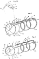
- Figure 6 is a plan view of the locking radial band of the present invention showing the protrusions and detents of the present invention; and
- Figure 7 is an isometric detail of a segment of the stent of the present invention shown positioned over a segment of an inflatable balloon catheter with the balloon shown in a deflated configuration.
- Referring initially to Figure 1, a self-expanding stent for structurally supporting the wall of a vessel in accordance with the present invention is shown and generally designated 10. For purposes of illustration, the
device 10 is shown operationally positioned after being advanced through the femoral artery and toward the heart 14 of thepatient 12. It is to be appreciated, however, that thedevice 10 is useful in vessels throughout the vascular system ofpatient 12 and may be introduced into the vessel wherever it is most convenient to do so. - Referring now to Figure 2, it may be seen that the
device 10 is formed as anelongated cylinder 16 having aninner surface 18 and anouter surface 20. Thecylinder 16 is formed from a series of radial bands which include distalradial band 22a, intermediate radial bands 22b and proximalradial band 22c. Each radial band 22 is interconnected by a firstelongated strip 24 and a secondelongated strip 26. It may be appreciated that theelongated cylinder 16 may be covered with thin substrates, such as Rayon fabric, without departing from the present invention. - The structural details of the present invention may be better appreciated by reference to Figure 3 where it may be seen that proximal
radial band 22c is formed to have a substantially circular shape with a firstradial edge 28 and a secondradial edge 30. Between the firstradial edge 28 and the secondradial edge 30, each radial band 22 is formed with aninner surface 32 and anouter surface 34. Each radial band 22 is formed to be non-continuous. As a result, each radial band 22 has afirst end 36 and asecond end 38. Thefirst end 36 andsecond end 38 of each radial band 22 partially overlap each other so that a portion of theinner surface 32 of each radial band 22 overlays and contiguously contacts the a portion of theouter surface 34 of the same radial band 22. Importantly, thefirst end 36 of the radial band 22 is moveable over theouter surface 34 of the radial band 22. Similarly, thesecond end 38 of the radial band 22 is moveable over theinner surface 32 of the radial band 22. The movement of thefirst end 36 andsecond end 38 allows theoverlap region 40 between thefirst end 36 of the radial band 22 and thesecond end 38 of the radial band 22 to increase or decrease. Increasing or decreasing theoverlap region 40 of the radial band 22 causes a corresponding increase or decrease in thediameter 42 of the radial band 22. - The relationship between the
overlap region 40 and thediameter 42 of the radial band 22 may be more easily appreciated by comparison between Figure 3, where the radial band 22 is shown with in an expanded configuration, Figure 4, where the radial band 22 is shown in an intermediate configuration, and Figure 5, where the radial band 22 is shown in a contracted configuration. Specifically, it may be seen that theoverlap region 40 of Figure 3 increases to theoverlap region 44 of Figure 4 and increases still further to the overlap region 46 of Figure 5. It may also he seen that thediameter 42 of Figure 3, decreases to diameter 48 in Figure 4 and decreases still further todiameter 50 of Figure 5. As the preceding discussion demonstrates, movement of thefirst end 36 andsecond end 38 allows theoverlap region 40 to be varied and allows the radial band 22 to move between the expanded configuration shown in Figure 3 and the contracted configuration shown in Figure 5. The resiliant material used to form each radial band 22 biases the iso-concentric movement of the radial bands 22. More specifically, it may be appreciated that, absent some restraint, each radial band 22 will iso-concentrically self-expand until the radial band 22 has nearly reached the expanded configuration of Figure 3. - Returning to Figure 3, it may be seen that the proximal
radial band 22c is formed to have afirst tab 52 and asecond tab 54. The inclusion offirst tab 52 andsecond tab 54 on proximalradial band 22c, identify proximalradial band 22c as a lockingradial band 56. For the purposes of the present invention, any number of the radial bands 22 included in thecylinder 16 may be configured as locking radial bands, like lockingradial band 56. -
First tab 52 andsecond tab 54 are both positioned to project from the firstradial edge 28 of the lockingradial band 56.First tab 52 is located to be substantially adjacent to thefirst end 36 of lockingradial band 56 andsecond tab 54 is located to be substantially adjacent to thesecond end 38 of lockingradial band 56. Bothfirst tab 52 andsecond tab 54 are folded, withfirst tab 52 folded radially inward and underinner surface 32 andsecond tab 54 folded radially outward and overouter surface 34. Functionally,first tab 52 functions as a clasp which holds thefirst end 36 of lockingradial band 56 against theouter surface 34 of lockingradial band 56. Similarly,second tab 54 functions as a clasp which holds thesecond end 38 of lockingradial band 56 against theinner surface 32 of lockingradial band 56. Importantly, the clasps formed by thefirst tab 52 and thesecond tab 54 maintain the ability of thefirst end 36 and thesecond end 38 of lockingradial band 56 to move over the lockingradial band 56. In this fashion, the ability of lockingradial band 56 to move iso-concentrically between the contracted configuration of Figure 5 and the expanded configuration of Figure 3, by changing theoverlap region 40, is maintained. - The structural details of the locking
radial band 56 may be more fully appreciated by reference to Figure 6 where a representativeradial locking band 56 is shown in an unrolled configuration. In Figure 6, it may be seen that thefirst tab 52 included in lockingradial band 56 is formed with aprotrusion 58. Theprotrusion 58 is positioned to face theinner surface 32 of lockingradial band 56 when thefirst tab 52 is folded radially inward and under theinner surface 32. In cooperation with theprotrusion 58, the present invention includes a series of detents 60a, 60b and 60c formed in theinner surface 32 of the lockingradial band 56. The detents 60a, 60b and 60c are shaped to receive theprotrusion 58 and are positioned at predetermined radial positions on theinner surface 32. As a result, as thefirst end 36 of the lockingradial band 56 moves over theouter surface 34 to expand the lockingradial band 56, theprotrusion 58 sequentially engages each of the detents 60a, 60b and 60c. The engagement between theprotrusion 58 and each of the detents 60a, 60b and 60c provides a locking mechanism which allows lockingradial band 56 to expand (by sequentially engaging each successive detent 60a, 60b and 60c) but tends to prevent subsequent contraction. Preferably, the detents 60a, 60b and 60c are positioned to provide the locking mechanism only as the lockingradial band 56 nears and reaches the fully expanded configuration of Figure 3. - As discussed in the preceding paragraphs, the combination of
protrusion 58 and detents 60a, 60b, 60c provide a locking mechanism for holding lockingradial band 56 in the expanded configuration or near expanded configuration. It may be appreciated however, that the use of protrusions, likeprotrusion 58 and detents, like detents 60a, 60b, 60c to form locking mechanisms is not limited to the lockingradial bands 56 and similar detents and protrusions may be included in any of the radial bands 22. - For the purposes of the present invention, the
second tab 54 included in lockingradial band 56 is also preferably formed with aprotrusion 62. Theprotrusion 62 is positioned to face theouter surface 34 of the lockingradial band 56 when thesecond tab 54 is folded radially outward and over theouter surface 34. In cooperation with theprotrusion 62, the present invention includes at least onedetent 64 formed in theouter surface 34 of the lockingradial band 56. Thedetent 64, included in theouter surface 34, is shaped to receive theprotrusion 62 included on thesecond tab 54 and is positioned at a predetermined radial position on theouter surface 34. The radial position of thedetent 64 included on theouter surface 34 brings theprotrusion 62 and thedetent 64 into engagement as the lockingradial band 56 reaches the contracted configuration of Figure 5. The engagement between theprotrusion 62 and thedetent 64 provides a locking mechanism which holds the lockingradial band 56 in the contracted configuration of Figure 5 until an adequate force is applied to release the locking mechanism and allow expansion of the lockingradial band 56. - Returning to Figure 3, it may be seen that each radial band 22 is distributed along a common axis to form the
elongated cylinder 16. Within theelongated cylinder 16, eachfirst end 36 of each radial band 22 is interconnected by the firstelongated strip 24. Additionally, eachsecond end 38 of each radial band 22 is interconnected by the secondelongated strip 26. Importantly, when thedevice 10 is configured into the expanded configuration shown in Figure 3 or the conntracted configuration shown in Figure 5, firstelongated strip 24 is positioned to be relatively close to secondelongated strip 26. As a result, theelongated cylinder 16 is free to flex along an axis defined by firstelongated strip 24 and secondelongated strip 26. The ability of theelongated cylinder 16 to flex along the axis defined by firstelongated strip 24 and secondelongated strip 26 allows thedevice 10 to be inserted through curved or winding vessels. Additionally, the ability of theelongated cylinder 16 to flex along the axis defined by firstelongated strip 24 and secondelongated strip 26 allows thedevice 10 to be expanded to support curved or winding vessels. - The
device 10 of the present invention may be preferably fabricated within a range of diameters and overall lengths. Specifically devices which range in diameter from 1.0 to 3.0 millimeters and range in length from ten to forty millimeters have been found to be preferable. The diameter of a givendevice 10 is determined, of course, by the length between thefirst end 36 and thesecond end 38 of each band 22. The overall length, however, depends on the number of radial bands 22, the width between the firstradial edge 30 and the secondradial edge 32 of each band 22, and the spacing between the radial bands 22. Generally, shorter devices may be fabricated using fewer radial bands 22. For instance, a first preferred embodiment of the present invention include a sequence of seven radial bands 22 of which two, the distalradial band 22a and the proximalradial band 22c are configured as lockingradial hands 56. Alternatively a second, longer, preferred embodiment of the present invention includes a sequence of thirteen radial bands 22 of which two, the distalradial band 22a and the proximalradial band 22c are configured as lockingradial bands 56. It will be appreciated that even longer embodiments with additional radial bands 22 are envisioned by the present invention. Structurally, longer sequences of radial bands may require additional support. Therefore, in cases where longer sequences of radial bands 22 are included, it may be desirable to configure one of more of the radial bands to have an increased width between the firstradial edge 30 and the secondradial edge 32. For instance, the radial band 22 positioned at the center of thedevice 10 of Figure 2 features an increased width of this nature. It may also be desirable to provide additional interconnections between one or more of the radial bands 22 when long sequences are utilized. - In general, many methods may be utilized for the construction of the
device 10 of the present invention. Practice has shown however, that it is highly practical to fabricate thedevice 10 by photo-chemical milling of a flat sheet of stainless steel. The photo-chemical milling may be used to produce the combination of radial bands 22, firstelongated strip 24 and secondelongated strip 26 in an unrolled configuration. The unrolled sheet is then rolled to form theelongated cylinder 16 of the present invention. - Insertion of the
device 10 into the vascular system (or other part of the body) begins, as shown in Figure 7, by placement of thedevice 10 over an inflatable balloon catheter 70. Once the device is positioned over the inflatable balloon 70, a compressive force is applied to each of the radial bands 22. The compressive force causes each of the radial bands 22 to move iso-concentrically to adopt the contracted configuration of Figure 5. As the radial bands 22 adopt the contracted configuration of Figure 5, theprotrusion 62 of each lockingradial band 56 engages thedetent 64 included in the same lockingradial band 56, locking the lockingradial band 56 in the contracted configuration of Figure 5. The locking action of the lockingradial bands 56 holds the device in position over the inflatable balloon 70 in a manner as best seen in Figure 7. - Once the
device 10 has been configured in the contracted configuration of Figure 5, and locked around the inflatable balloon 70, a placement catheter (such as theplacement catheter 72, shown in Figure 1) is inserted into a vessel where thedevice 10 is to be deployed. Thedevice 10 and balloon 70 are then advanced through the placement catheter and into the vessel and towards the target site. Once the target site has been reached, the balloon 70 is partially inflated. The partial inflation of the balloon unlocks each of the lockingradial bands 56 by removing theprotrusion 62 from thedetent 64 of the lockingradial band 56. - Once the locking
radial bands 56 are unlocked, the resilient material of the radial bands 22 causes the radial bands 22 to self-expand from the contracted configuration of Figure 5 to reach a nearly expanded configuration, such as the intermediate configuration shown in Figure 4. The balloon 70 may then be more fully inflated to further expand each of the radial bands 22. In particular, each radial band 22 may be expanded until theprotrusion 58 engages detent 60a, 60b or 60c. Importantly, each radial band 22 may be individually expanded to reach an individual degree of expansion. In this fashion, thedevice 10 may be adapted to support tapered or otherwise irregular vessels. Once thedevice 10 has been properly expanded, the balloon 70 may be deflated and the balloon 70 and placement catheter may be removed, completing the procedure. - In some cases, internal pressure within a vessel may exceed the strength of a particular vascular segment. In such cases, the present invention may be reconfigured to provide a reinforcing stent adding a thin layer of material, such as Rayon, over the
elongated cylinder 16. Insertion of the modified device generally follows the operational sequence outlined in the preceding paragraphs. - While the particular expandable stent as herein shown and disclosed in detail is fully capable of obtaining the objects and providing the advantages herein before stated, it is to be understood that it is merely illustrative of the presently preferred embodiments of the invention and that no limitations are intended to the details of construction or design herein shown other than as described in the appended claims.
Claims (23)
- A self-expanding stent for placement in a vessel which comprises:a plurality of radial bands, one of said bands being a proximal radial band and one of said bands being a distal radial band, each said band having a first radial edge and a second radial edge, with an inner surface and an outer surface between said edges, each said band also having a first end and a second end with said first end overlapping said second end to create an overlap region, said first end being moveable relative to said second end to iso-concentrically reconfigure each band between a contracted configuration having a first diameter and an expanded configuration having a second diameter;at least one tab projecting from said first radial edge of said proximal radial band for folding said tab over said proximal radial band to hold said first end and said second end of said proximal radial band against said proximal radial band in said overlap region;at least one tab projecting from said second radial edge of said distal radial band for folding said tab over said distal radial band to hold said first end and said second end of said distal radial band against said distal radial band in said overlap region;a first elongated strip, said elongated strip interconnecting said first end of each said radial band; anda second elongated strip, said elongated strip interconnecting said second end of each said radial band.
- A self-expanding stent as recited in claim 1 wherein said stent is fabricated as a single piece of stainless steel.
- A self-expanding stent as recited in claim 1 wherein each said tab projecting from said distal radial band is formed with a protrusion, said protrusion oriented to face said distal radial band when said tab is folded over said distal radial band.
- A self-expanding stent as recited in claim 3 wherein said distal radial band is formed with a first detent, said first detent being positioned to engage one said protrusion when said distal radial band is configured in said contracted configuration.
- A self-expanding stent as recited in claim 3 wherein said distal radial band is formed with a second detent, said second detent being positioned to engage one said protrusion when said distal radial band is configured in said expanded configuration.
- A self-expanding stent as recited in claim 3 wherein said distal radial band is formed with at least one additional detent, said additional detent being positioned to engage one said protrusion when said distal radial band is configured between said contracted configuration and said expanded configuration.
- A self-expanding stent as recited in claim 1 wherein each said tab projecting from said proximal radial band is formed with a protrusion, said protrusion oriented to face said proximal radial band when said tab is folded over said proximal radial band.
- A self-expanding stent as recited in claim 3 wherein said proximal radial band is formed with a first detent, said first detent being positioned to engage one said protrusion when said proximal radial band is configured in said contracted configuration.
- A self-expanding stent as recited in claim 3 wherein said proximal radial band is formed with a second detent, said second detent being positioned to engage one said protrusion when said proximal radial band is configured in said expanded configuration.
- A self-expanding stent as recited in claim 3 wherein said proximal radial band is formed with at least one additional detent, said additional detent being positioned to engage one said protrusion when said proximal radial band is configured between said contracted configuration and said expanded configuration.
- A self-expanding stent as recited in claim 1 wherein said second diameter of said expanded configuration is in the range of 1.0 to 3.0 millimeters.
- A self-expanding stent as recited in claim 1 wherein said expandable stent has an overall length in the range of ten to forty millimeters.
- A self-expanding stent for placement in a vessel which comprises:a plurality of radial bands, at least one of said bands being a locking radial band, each said band having a first radial edge and a second radial edge, each said band also having a first end and a second end, said first end overlapping said second end to create an overlap region, said first end being moveable relative to said second end to iso-concentrically reconfigure each band between a contracted configuration having a first diameter and an expanded configuration having a second diameter;at least one tab projecting from said first radial edge of each said locking radial band for folding said tab over said locking radial band to hold said first end and said second end of said locking radial band against said locking radial band in said overlap region;means for interconnecting said first end of each said radial band;means for interconnecting said second end of each said radial band; andmeans for selectively locking said locking radial band in said contracted configuration and said expanded configuration.
- A self-expanding stent as recited in claim 13 wherein said locking means includes a protrusion attached to each said tab, said protrusion oriented to face said locking radial band when said tab is folded over said locking radial band.
- A self-expanding stent as recited in claim 14 wherein said locking radial band is formed with a first detent, said first detent being positioned to engage said protrusion when said locking radial band is configured in said contracted configuration.
- A self-expanding stent as recited in claim 14 wherein said locking radial band is formed with a second detent, said second detent being positioned to engage said protrusion when said locking radial band is configured in said expanded configuration.
- A self-expanding stent as recited in claim 14 wherein said locking radial band is formed with at least one additional detent, said additional detent being positioned to engage said protrusion when said locking radial band is configured between said contracted configuration and said expanded configuration.
- A self-expanding stent as recited in claim 13 further comprising a thin, permeable substrate, said substrate applied to substantially cover said outer surface of said elongated cylinder.
- A self-expanding stent as recited in claim 11 wherein said second diameter of said expanded configuration is in the range of 1.0 to 3.0 millimeters.
- A self-expanding stent as recited in claim 11 wherein said expandable stent has an overall length in the range of ten to forty millimeters.
- A method for placing a self-expanding stent at a target site in a vessel of a patient which comprises the steps of:providing a self-expanding stent which comprises a plurality of radial bands, at least one of said bands being a locking radial band, each said band having a first radial edge and a second radial edge, each said band also having a first end and a second end, said first end overlapping said second end to create an overlap region, said first end being moveable relative to said second end to iso-concentrically reconfigure each band between a contracted configuration having a first diameter and an expanded configuration having a second diameter, at least one tab projecting from said first radial edge of each said locking radial band for folding said tab over said locking radial band to hold said first end and said second end of said locking radial band against said locking radial band in said overlap region, means for interconnecting said first end of each said radial band, means interconnecting said second end of each said radial band, and means for selectively locking said locking radial band in said contracted configuration and said expanded configuration;providing an inflatable balloon catheter;providing a placement catheter;positioning said stent over said inflatable balloon catheter;configuring said stent to a contracted configuration;inserting said expandable stent and said inflatable balloon in said placement catheter;inserting said placement catheter into said vessel;advancing said expandable stent and said inflatable balloon distally out of said placement catheter;advancing said expandable stent and said inflatable balloon to said target site;partially inflating said balloon to unlock said radial bands and allow said radial bands to resiliently self-expand.
- A method as recited in claim 21 which further comprises the step of further inflating said balloon to further expand said radial bands.
- A method as recited in claim 22 which further comprises the steps of:deflating said balloon;repositioning said balloon;reinflating said balloon to further expand a particular band within said plurality of bands.
Applications Claiming Priority (2)
| Application Number | Priority Date | Filing Date | Title |
|---|---|---|---|
| US557725 | 1995-11-13 | ||
| US08/557,725 US5643314A (en) | 1995-11-13 | 1995-11-13 | Self-expanding stent |
Publications (3)
| Publication Number | Publication Date |
|---|---|
| EP0773006A2 true EP0773006A2 (en) | 1997-05-14 |
| EP0773006A3 EP0773006A3 (en) | 1997-12-29 |
| EP0773006B1 EP0773006B1 (en) | 2003-03-12 |
Family
ID=24226647
Family Applications (1)
| Application Number | Title | Priority Date | Filing Date |
|---|---|---|---|
| EP96118066A Expired - Lifetime EP0773006B1 (en) | 1995-11-13 | 1996-11-11 | Self-expanding stent |
Country Status (5)
| Country | Link |
|---|---|
| US (1) | US5643314A (en) |
| EP (1) | EP0773006B1 (en) |
| JP (1) | JP3143595B2 (en) |
| CA (1) | CA2189463C (en) |
| DE (1) | DE69626600T2 (en) |
Cited By (3)
| Publication number | Priority date | Publication date | Assignee | Title |
|---|---|---|---|---|
| WO1999018890A1 (en) * | 1997-10-15 | 1999-04-22 | Navius Corporation | Stent and method for making a stent |
| WO1999040874A1 (en) * | 1998-02-17 | 1999-08-19 | Steinke Thomas A | Expandable stent |
| WO2000025701A1 (en) * | 1998-11-04 | 2000-05-11 | Alain Fouere | Endovascular prosthesis made of several elements for intracranial aneurysms |
Families Citing this family (54)
| Publication number | Priority date | Publication date | Assignee | Title |
|---|---|---|---|---|
| US5836964A (en) * | 1996-10-30 | 1998-11-17 | Medinol Ltd. | Stent fabrication method |
| CA2258732C (en) * | 1996-06-20 | 2006-04-04 | Sulzer Vascutek Ltd. | Prosthetic repair of body passages |
| US5868781A (en) * | 1996-10-22 | 1999-02-09 | Scimed Life Systems, Inc. | Locking stent |
| US7959664B2 (en) * | 1996-12-26 | 2011-06-14 | Medinol, Ltd. | Flat process of drug coating for stents |
| US8663311B2 (en) | 1997-01-24 | 2014-03-04 | Celonova Stent, Inc. | Device comprising biodegradable bistable or multistable cells and methods of use |
| US8353948B2 (en) * | 1997-01-24 | 2013-01-15 | Celonova Stent, Inc. | Fracture-resistant helical stent incorporating bistable cells and methods of use |
| IL131063A (en) | 1997-01-24 | 2005-07-25 | Kentucky Oil N V | Bistable spring construction for a stent and other medical apparatus |
| US5954765A (en) * | 1997-11-03 | 1999-09-21 | Ruiz; Carlos E. | Self-adjusting prosthesis for treating constrictions in growing vessels |
| US6623521B2 (en) | 1998-02-17 | 2003-09-23 | Md3, Inc. | Expandable stent with sliding and locking radial elements |
| US6224626B1 (en) | 1998-02-17 | 2001-05-01 | Md3, Inc. | Ultra-thin expandable stent |
| US20040254635A1 (en) | 1998-03-30 | 2004-12-16 | Shanley John F. | Expandable medical device for delivery of beneficial agent |
| US7208010B2 (en) | 2000-10-16 | 2007-04-24 | Conor Medsystems, Inc. | Expandable medical device for delivery of beneficial agent |
| US7208011B2 (en) | 2001-08-20 | 2007-04-24 | Conor Medsystems, Inc. | Implantable medical device with drug filled holes |
| US6241762B1 (en) | 1998-03-30 | 2001-06-05 | Conor Medsystems, Inc. | Expandable medical device with ductile hinges |
| US6293967B1 (en) | 1998-10-29 | 2001-09-25 | Conor Medsystems, Inc. | Expandable medical device with ductile hinges |
| NL1011903C2 (en) * | 1999-02-05 | 2000-08-08 | Surgical Innovations Vof | Removable stent. |
| US6231597B1 (en) | 1999-02-16 | 2001-05-15 | Mark E. Deem | Apparatus and methods for selectively stenting a portion of a vessel wall |
| US6162237A (en) * | 1999-04-19 | 2000-12-19 | Chan; Winston Kam Yew | Temporary intravascular stent for use in retrohepatic IVC or hepatic vein injury |
| US6245101B1 (en) | 1999-05-03 | 2001-06-12 | William J. Drasler | Intravascular hinge stent |
| US8016873B1 (en) | 1999-05-03 | 2011-09-13 | Drasler William J | Intravascular hinge stent |
| US6290673B1 (en) * | 1999-05-20 | 2001-09-18 | Conor Medsystems, Inc. | Expandable medical device delivery system and method |
| AU775465B2 (en) * | 1999-10-20 | 2004-08-05 | Warsaw Orthopedic, Inc. | Impacted orthopedic bone support implant |
| ES2262642T3 (en) * | 2000-04-05 | 2006-12-01 | Kyphon Inc. | DEVICE FOR THE TREATMENT OF FRACTURED AND / OR SICK BONES. |
| US6799637B2 (en) | 2000-10-20 | 2004-10-05 | Schlumberger Technology Corporation | Expandable tubing and method |
| US6764507B2 (en) | 2000-10-16 | 2004-07-20 | Conor Medsystems, Inc. | Expandable medical device with improved spatial distribution |
| DE20122506U1 (en) | 2000-10-16 | 2005-12-08 | Conor Medsystems, Inc., Menlo Park | Expandable medical device for delivering a beneficial agent |
| US20020103526A1 (en) * | 2000-12-15 | 2002-08-01 | Tom Steinke | Protective coating for stent |
| NO335594B1 (en) | 2001-01-16 | 2015-01-12 | Halliburton Energy Serv Inc | Expandable devices and methods thereof |
| US6964680B2 (en) * | 2001-02-05 | 2005-11-15 | Conor Medsystems, Inc. | Expandable medical device with tapered hinge |
| US20040073294A1 (en) | 2002-09-20 | 2004-04-15 | Conor Medsystems, Inc. | Method and apparatus for loading a beneficial agent into an expandable medical device |
| US7056338B2 (en) | 2003-03-28 | 2006-06-06 | Conor Medsystems, Inc. | Therapeutic agent delivery device with controlled therapeutic agent release rates |
| US6589286B1 (en) * | 2001-09-12 | 2003-07-08 | Jason Litner | Eustachian tube stent |
| US20040127976A1 (en) * | 2002-09-20 | 2004-07-01 | Conor Medsystems, Inc. | Method and apparatus for loading a beneficial agent into an expandable medical device |
| EP1610823B1 (en) | 2003-03-28 | 2011-09-28 | Innovational Holdings, LLC | Implantable medical device with continuous agent concentration gradient |
| US7169179B2 (en) | 2003-06-05 | 2007-01-30 | Conor Medsystems, Inc. | Drug delivery device and method for bi-directional drug delivery |
| US7785653B2 (en) | 2003-09-22 | 2010-08-31 | Innovational Holdings Llc | Method and apparatus for loading a beneficial agent into an expandable medical device |
| US7763065B2 (en) | 2004-07-21 | 2010-07-27 | Reva Medical, Inc. | Balloon expandable crush-recoverable stent device |
| US8292944B2 (en) | 2004-12-17 | 2012-10-23 | Reva Medical, Inc. | Slide-and-lock stent |
| US9149378B2 (en) | 2005-08-02 | 2015-10-06 | Reva Medical, Inc. | Axially nested slide and lock expandable device |
| US7914574B2 (en) | 2005-08-02 | 2011-03-29 | Reva Medical, Inc. | Axially nested slide and lock expandable device |
| US8828077B2 (en) | 2006-03-15 | 2014-09-09 | Medinol Ltd. | Flat process of preparing drug eluting stents |
| US8652192B2 (en) * | 2006-03-31 | 2014-02-18 | St. Jude Medical, Cardiology Division, Inc. | Stent and system and method for deploying a stent |
| US7704275B2 (en) | 2007-01-26 | 2010-04-27 | Reva Medical, Inc. | Circumferentially nested expandable device |
| US9017395B2 (en) * | 2007-03-09 | 2015-04-28 | Novostent Corporation | Vascular prosthesis and methods of use |
| US8974514B2 (en) | 2007-03-13 | 2015-03-10 | Abbott Cardiovascular Systems Inc. | Intravascular stent with integrated link and ring strut |
| US20090105806A1 (en) * | 2007-10-23 | 2009-04-23 | Endologix, Inc | Stent |
| EP2211773A4 (en) | 2007-11-30 | 2015-07-29 | Reva Medical Inc | Axially-radially nested expandable device |
| CN102245127B (en) * | 2008-10-10 | 2014-06-11 | 雷瓦医药公司 | Expandable slide and lock stent |
| CA2759817A1 (en) | 2009-06-05 | 2010-12-09 | Entrigue Surgical, Inc. | Systems and devices for providing therapy of an anatomical structure |
| US20110112623A1 (en) * | 2009-11-10 | 2011-05-12 | Schatz Richard A | System and Method for Placing a Coronary Stent at the Ostium of a Blood Vessel |
| CN102843997B (en) | 2010-04-10 | 2015-02-25 | 雷瓦医药公司 | Expandable slide and lock stent |
| AU2011305256A1 (en) | 2010-09-24 | 2013-04-11 | Entrigue Surgical, Inc. | Systems, devices, and methods for providing therapy to an anatomical structure using high frequency pressure waves and/or cryogenic temperatures |
| US9408732B2 (en) | 2013-03-14 | 2016-08-09 | Reva Medical, Inc. | Reduced-profile slide and lock stent |
| CN104127268A (en) * | 2014-06-16 | 2014-11-05 | 苏州固基电子科技有限公司 | Vascular stent firm in supporting |
Citations (5)
| Publication number | Priority date | Publication date | Assignee | Title |
|---|---|---|---|---|
| EP0382014A1 (en) * | 1989-01-26 | 1990-08-16 | Advanced Cardiovascular Systems, Inc. | Intravascular endoprothesis |
| WO1991017789A1 (en) * | 1990-05-18 | 1991-11-28 | Stack Richard S | Bioabsorbable stent |
| US5100429A (en) * | 1989-04-28 | 1992-03-31 | C. R. Bard, Inc. | Endovascular stent and delivery system |
| WO1994021196A2 (en) * | 1993-03-18 | 1994-09-29 | C.R. Bard, Inc. | Endovascular stents |
| EP0621017A1 (en) * | 1993-04-23 | 1994-10-26 | Advanced Cardiovascular Systems, Inc. | Ratcheting stent |
Family Cites Families (23)
| Publication number | Priority date | Publication date | Assignee | Title |
|---|---|---|---|---|
| US3278176A (en) * | 1964-10-05 | 1966-10-11 | Abolins Andrew | Split compression spring for radial assembly |
| US3842441A (en) * | 1972-10-12 | 1974-10-22 | A Kaiser | A temporary implant and method for tendon surgery |
| SE424045B (en) * | 1979-01-12 | 1982-06-28 | Tesi Ab | CATHETER |
| US4214587A (en) * | 1979-02-12 | 1980-07-29 | Sakura Chester Y Jr | Anastomosis device and method |
| AT392733B (en) * | 1981-09-16 | 1991-05-27 | Medinvent Sa | DEVICE FOR TREATING BLOOD VESSELS OR THE LIKE. |
| US4512338A (en) * | 1983-01-25 | 1985-04-23 | Balko Alexander B | Process for restoring patency to body vessels |
| ES8705239A1 (en) * | 1984-12-05 | 1987-05-01 | Medinvent Sa | A device for implantation and a method of implantation in a vessel using such device. |
| US4733665C2 (en) * | 1985-11-07 | 2002-01-29 | Expandable Grafts Partnership | Expandable intraluminal graft and method and apparatus for implanting an expandable intraluminal graft |
| US4878906A (en) * | 1986-03-25 | 1989-11-07 | Servetus Partnership | Endoprosthesis for repairing a damaged vessel |
| US4740207A (en) * | 1986-09-10 | 1988-04-26 | Kreamer Jeffry W | Intralumenal graft |
| US4793348A (en) * | 1986-11-15 | 1988-12-27 | Palmaz Julio C | Balloon expandable vena cava filter to prevent migration of lower extremity venous clots into the pulmonary circulation |
| US4907336A (en) * | 1987-03-13 | 1990-03-13 | Cook Incorporated | Method of making an endovascular stent and delivery system |
| US4800882A (en) * | 1987-03-13 | 1989-01-31 | Cook Incorporated | Endovascular stent and delivery system |
| US4969458A (en) * | 1987-07-06 | 1990-11-13 | Medtronic, Inc. | Intracoronary stent and method of simultaneous angioplasty and stent implant |
| US4886062A (en) * | 1987-10-19 | 1989-12-12 | Medtronic, Inc. | Intravascular radially expandable stent and method of implant |
| JP2720187B2 (en) * | 1988-03-11 | 1998-02-25 | 日本ゼオン株式会社 | Medical shape memory alloy members and cartels |
| US5019090A (en) * | 1988-09-01 | 1991-05-28 | Corvita Corporation | Radially expandable endoprosthesis and the like |
| US4913141A (en) * | 1988-10-25 | 1990-04-03 | Cordis Corporation | Apparatus and method for placement of a stent within a subject vessel |
| US4856516A (en) * | 1989-01-09 | 1989-08-15 | Cordis Corporation | Endovascular stent apparatus and method |
| JP2772665B2 (en) * | 1989-03-29 | 1998-07-02 | 日本ゼオン株式会社 | Living organ dilator and living organ dilator |
| US5344426A (en) * | 1990-04-25 | 1994-09-06 | Advanced Cardiovascular Systems, Inc. | Method and system for stent delivery |
| FR2683449A1 (en) * | 1991-11-08 | 1993-05-14 | Cardon Alain | ENDOPROTHESIS FOR TRANSLUMINAL IMPLANTATION. |
| US5449373A (en) * | 1994-03-17 | 1995-09-12 | Medinol Ltd. | Articulated stent |
-
1995
- 1995-11-13 US US08/557,725 patent/US5643314A/en not_active Expired - Lifetime
-
1996
- 1996-11-01 CA CA002189463A patent/CA2189463C/en not_active Expired - Fee Related
- 1996-11-11 EP EP96118066A patent/EP0773006B1/en not_active Expired - Lifetime
- 1996-11-11 DE DE69626600T patent/DE69626600T2/en not_active Expired - Lifetime
- 1996-11-12 JP JP30058196A patent/JP3143595B2/en not_active Expired - Lifetime
Patent Citations (5)
| Publication number | Priority date | Publication date | Assignee | Title |
|---|---|---|---|---|
| EP0382014A1 (en) * | 1989-01-26 | 1990-08-16 | Advanced Cardiovascular Systems, Inc. | Intravascular endoprothesis |
| US5100429A (en) * | 1989-04-28 | 1992-03-31 | C. R. Bard, Inc. | Endovascular stent and delivery system |
| WO1991017789A1 (en) * | 1990-05-18 | 1991-11-28 | Stack Richard S | Bioabsorbable stent |
| WO1994021196A2 (en) * | 1993-03-18 | 1994-09-29 | C.R. Bard, Inc. | Endovascular stents |
| EP0621017A1 (en) * | 1993-04-23 | 1994-10-26 | Advanced Cardiovascular Systems, Inc. | Ratcheting stent |
Cited By (3)
| Publication number | Priority date | Publication date | Assignee | Title |
|---|---|---|---|---|
| WO1999018890A1 (en) * | 1997-10-15 | 1999-04-22 | Navius Corporation | Stent and method for making a stent |
| WO1999040874A1 (en) * | 1998-02-17 | 1999-08-19 | Steinke Thomas A | Expandable stent |
| WO2000025701A1 (en) * | 1998-11-04 | 2000-05-11 | Alain Fouere | Endovascular prosthesis made of several elements for intracranial aneurysms |
Also Published As
| Publication number | Publication date |
|---|---|
| DE69626600T2 (en) | 2004-03-11 |
| CA2189463A1 (en) | 1997-05-14 |
| EP0773006A3 (en) | 1997-12-29 |
| JP3143595B2 (en) | 2001-03-07 |
| JPH09192234A (en) | 1997-07-29 |
| EP0773006B1 (en) | 2003-03-12 |
| US5643314A (en) | 1997-07-01 |
| CA2189463C (en) | 2000-01-11 |
| DE69626600D1 (en) | 2003-04-17 |
Similar Documents
| Publication | Publication Date | Title |
|---|---|---|
| US5643314A (en) | Self-expanding stent | |
| US11911304B2 (en) | Apparatus and methods for delivering stents | |
| US5443500A (en) | Intravascular stent | |
| AU751389B2 (en) | Deformable scaffolding multicellular stent | |
| JP4294858B2 (en) | Stent and method for manufacturing stent | |
| US5735872A (en) | Stent | |
| EP1326555B1 (en) | Selectively thinned coiled-sheet stents and methods for making them | |
| US6322585B1 (en) | Coiled-sheet stent-graft with slidable exo-skeleton | |
| CA1330186C (en) | Expandable intraluminal graft | |
| US7223284B2 (en) | Coiled-sheet stent-graft with slidable exo-skeleton | |
| US6491719B1 (en) | Tubular endoluminar prosthesis having oblique ends | |
| JPH11221288A (en) | Prosthesis with multiple bridge type joint part for endoscopic operation and operation thereof | |
| US20080208317A1 (en) | Anchoring Device for Stent | |
| JPH0572820B2 (en) | ||
| EP1194079B1 (en) | Flexible, stretchable coiled-sheet stent | |
| EP1488762B1 (en) | Coiled-sheet stent with flexible mesh design | |
| MXPA97003845A (en) | Endoprotesis of interlocking resistant to crush, of expansion with gl |
Legal Events
| Date | Code | Title | Description |
|---|---|---|---|
| PUAI | Public reference made under article 153(3) epc to a published international application that has entered the european phase |
Free format text: ORIGINAL CODE: 0009012 |
|
| AK | Designated contracting states |
Kind code of ref document: A2 Designated state(s): DE FR IT NL |
|
| PUAL | Search report despatched |
Free format text: ORIGINAL CODE: 0009013 |
|
| AK | Designated contracting states |
Kind code of ref document: A3 Designated state(s): DE FR IT NL |
|
| 17P | Request for examination filed |
Effective date: 19980116 |
|
| RAP1 | Party data changed (applicant data changed or rights of an application transferred) |
Owner name: ENDOSONICS CORPORATION |
|
| 17Q | First examination report despatched |
Effective date: 20010314 |
|
| GRAG | Despatch of communication of intention to grant |
Free format text: ORIGINAL CODE: EPIDOS AGRA |
|
| GRAG | Despatch of communication of intention to grant |
Free format text: ORIGINAL CODE: EPIDOS AGRA |
|
| GRAH | Despatch of communication of intention to grant a patent |
Free format text: ORIGINAL CODE: EPIDOS IGRA |
|
| RAP1 | Party data changed (applicant data changed or rights of an application transferred) |
Owner name: JOMED INC., |
|
| GRAH | Despatch of communication of intention to grant a patent |
Free format text: ORIGINAL CODE: EPIDOS IGRA |
|
| GRAA | (expected) grant |
Free format text: ORIGINAL CODE: 0009210 |
|
| RIN1 | Information on inventor provided before grant (corrected) |
Inventor name: JUNG, EUGENE J., JR Inventor name: ROUCHER, LEO R., JR Inventor name: CARPENTER, KENNETH W. |
|
| AK | Designated contracting states |
Designated state(s): DE FR IT NL |
|
| PG25 | Lapsed in a contracting state [announced via postgrant information from national office to epo] |
Ref country code: NL Free format text: LAPSE BECAUSE OF FAILURE TO SUBMIT A TRANSLATION OF THE DESCRIPTION OR TO PAY THE FEE WITHIN THE PRESCRIBED TIME-LIMIT Effective date: 20030312 Ref country code: IT Free format text: LAPSE BECAUSE OF FAILURE TO SUBMIT A TRANSLATION OF THE DESCRIPTION OR TO PAY THE FEE WITHIN THE PRESCRIBED TIME-LIMIT;WARNING: LAPSES OF ITALIAN PATENTS WITH EFFECTIVE DATE BEFORE 2007 MAY HAVE OCCURRED AT ANY TIME BEFORE 2007. THE CORRECT EFFECTIVE DATE MAY BE DIFFERENT FROM THE ONE RECORDED. Effective date: 20030312 |
|
| REF | Corresponds to: |
Ref document number: 69626600 Country of ref document: DE Date of ref document: 20030417 Kind code of ref document: P |
|
| NLV1 | Nl: lapsed or annulled due to failure to fulfill the requirements of art. 29p and 29m of the patents act | ||
| ET | Fr: translation filed | ||
| PLBE | No opposition filed within time limit |
Free format text: ORIGINAL CODE: 0009261 |
|
| STAA | Information on the status of an ep patent application or granted ep patent |
Free format text: STATUS: NO OPPOSITION FILED WITHIN TIME LIMIT |
|
| 26N | No opposition filed |
Effective date: 20031215 |
|
| REG | Reference to a national code |
Ref country code: FR Ref legal event code: TP |
|
| REG | Reference to a national code |
Ref country code: FR Ref legal event code: PLFP Year of fee payment: 20 |
|
| PGFP | Annual fee paid to national office [announced via postgrant information from national office to epo] |
Ref country code: DE Payment date: 20151130 Year of fee payment: 20 |
|
| PGFP | Annual fee paid to national office [announced via postgrant information from national office to epo] |
Ref country code: FR Payment date: 20151027 Year of fee payment: 20 |
|
| REG | Reference to a national code |
Ref country code: DE Ref legal event code: R071 Ref document number: 69626600 Country of ref document: DE |