EP0773166A1 - Carbon film-coated plastic container - Google Patents
Carbon film-coated plastic container Download PDFInfo
- Publication number
- EP0773166A1 EP0773166A1 EP95927996A EP95927996A EP0773166A1 EP 0773166 A1 EP0773166 A1 EP 0773166A1 EP 95927996 A EP95927996 A EP 95927996A EP 95927996 A EP95927996 A EP 95927996A EP 0773166 A1 EP0773166 A1 EP 0773166A1
- Authority
- EP
- European Patent Office
- Prior art keywords
- resin
- container
- film
- plastic
- carbon film
- Prior art date
- Legal status (The legal status is an assumption and is not a legal conclusion. Google has not performed a legal analysis and makes no representation as to the accuracy of the status listed.)
- Granted
Links
Images


Classifications
-
- C—CHEMISTRY; METALLURGY
- C23—COATING METALLIC MATERIAL; COATING MATERIAL WITH METALLIC MATERIAL; CHEMICAL SURFACE TREATMENT; DIFFUSION TREATMENT OF METALLIC MATERIAL; COATING BY VACUUM EVAPORATION, BY SPUTTERING, BY ION IMPLANTATION OR BY CHEMICAL VAPOUR DEPOSITION, IN GENERAL; INHIBITING CORROSION OF METALLIC MATERIAL OR INCRUSTATION IN GENERAL
- C23C—COATING METALLIC MATERIAL; COATING MATERIAL WITH METALLIC MATERIAL; SURFACE TREATMENT OF METALLIC MATERIAL BY DIFFUSION INTO THE SURFACE, BY CHEMICAL CONVERSION OR SUBSTITUTION; COATING BY VACUUM EVAPORATION, BY SPUTTERING, BY ION IMPLANTATION OR BY CHEMICAL VAPOUR DEPOSITION, IN GENERAL
- C23C16/00—Chemical coating by decomposition of gaseous compounds, without leaving reaction products of surface material in the coating, i.e. chemical vapour deposition [CVD] processes
-
- B—PERFORMING OPERATIONS; TRANSPORTING
- B65—CONVEYING; PACKING; STORING; HANDLING THIN OR FILAMENTARY MATERIAL
- B65D—CONTAINERS FOR STORAGE OR TRANSPORT OF ARTICLES OR MATERIALS, e.g. BAGS, BARRELS, BOTTLES, BOXES, CANS, CARTONS, CRATES, DRUMS, JARS, TANKS, HOPPERS, FORWARDING CONTAINERS; ACCESSORIES, CLOSURES, OR FITTINGS THEREFOR; PACKAGING ELEMENTS; PACKAGES
- B65D1/00—Containers having bodies formed in one piece, e.g. by casting metallic material, by moulding plastics, by blowing vitreous material, by throwing ceramic material, by moulding pulped fibrous material, by deep-drawing operations performed on sheet material
- B65D1/02—Bottles or similar containers with necks or like restricted apertures, designed for pouring contents
- B65D1/0207—Bottles or similar containers with necks or like restricted apertures, designed for pouring contents characterised by material, e.g. composition, physical features
- B65D1/0215—Bottles or similar containers with necks or like restricted apertures, designed for pouring contents characterised by material, e.g. composition, physical features multilayered
-
- B—PERFORMING OPERATIONS; TRANSPORTING
- B65—CONVEYING; PACKING; STORING; HANDLING THIN OR FILAMENTARY MATERIAL
- B65D—CONTAINERS FOR STORAGE OR TRANSPORT OF ARTICLES OR MATERIALS, e.g. BAGS, BARRELS, BOTTLES, BOXES, CANS, CARTONS, CRATES, DRUMS, JARS, TANKS, HOPPERS, FORWARDING CONTAINERS; ACCESSORIES, CLOSURES, OR FITTINGS THEREFOR; PACKAGING ELEMENTS; PACKAGES
- B65D23/00—Details of bottles or jars not otherwise provided for
- B65D23/02—Linings or internal coatings
-
- C—CHEMISTRY; METALLURGY
- C23—COATING METALLIC MATERIAL; COATING MATERIAL WITH METALLIC MATERIAL; CHEMICAL SURFACE TREATMENT; DIFFUSION TREATMENT OF METALLIC MATERIAL; COATING BY VACUUM EVAPORATION, BY SPUTTERING, BY ION IMPLANTATION OR BY CHEMICAL VAPOUR DEPOSITION, IN GENERAL; INHIBITING CORROSION OF METALLIC MATERIAL OR INCRUSTATION IN GENERAL
- C23C—COATING METALLIC MATERIAL; COATING MATERIAL WITH METALLIC MATERIAL; SURFACE TREATMENT OF METALLIC MATERIAL BY DIFFUSION INTO THE SURFACE, BY CHEMICAL CONVERSION OR SUBSTITUTION; COATING BY VACUUM EVAPORATION, BY SPUTTERING, BY ION IMPLANTATION OR BY CHEMICAL VAPOUR DEPOSITION, IN GENERAL
- C23C16/00—Chemical coating by decomposition of gaseous compounds, without leaving reaction products of surface material in the coating, i.e. chemical vapour deposition [CVD] processes
- C23C16/04—Coating on selected surface areas, e.g. using masks
- C23C16/045—Coating cavities or hollow spaces, e.g. interior of tubes; Infiltration of porous substrates
-
- C—CHEMISTRY; METALLURGY
- C23—COATING METALLIC MATERIAL; COATING MATERIAL WITH METALLIC MATERIAL; CHEMICAL SURFACE TREATMENT; DIFFUSION TREATMENT OF METALLIC MATERIAL; COATING BY VACUUM EVAPORATION, BY SPUTTERING, BY ION IMPLANTATION OR BY CHEMICAL VAPOUR DEPOSITION, IN GENERAL; INHIBITING CORROSION OF METALLIC MATERIAL OR INCRUSTATION IN GENERAL
- C23C—COATING METALLIC MATERIAL; COATING MATERIAL WITH METALLIC MATERIAL; SURFACE TREATMENT OF METALLIC MATERIAL BY DIFFUSION INTO THE SURFACE, BY CHEMICAL CONVERSION OR SUBSTITUTION; COATING BY VACUUM EVAPORATION, BY SPUTTERING, BY ION IMPLANTATION OR BY CHEMICAL VAPOUR DEPOSITION, IN GENERAL
- C23C16/00—Chemical coating by decomposition of gaseous compounds, without leaving reaction products of surface material in the coating, i.e. chemical vapour deposition [CVD] processes
- C23C16/22—Chemical coating by decomposition of gaseous compounds, without leaving reaction products of surface material in the coating, i.e. chemical vapour deposition [CVD] processes characterised by the deposition of inorganic material, other than metallic material
- C23C16/26—Deposition of carbon only
-
- C—CHEMISTRY; METALLURGY
- C23—COATING METALLIC MATERIAL; COATING MATERIAL WITH METALLIC MATERIAL; CHEMICAL SURFACE TREATMENT; DIFFUSION TREATMENT OF METALLIC MATERIAL; COATING BY VACUUM EVAPORATION, BY SPUTTERING, BY ION IMPLANTATION OR BY CHEMICAL VAPOUR DEPOSITION, IN GENERAL; INHIBITING CORROSION OF METALLIC MATERIAL OR INCRUSTATION IN GENERAL
- C23C—COATING METALLIC MATERIAL; COATING MATERIAL WITH METALLIC MATERIAL; SURFACE TREATMENT OF METALLIC MATERIAL BY DIFFUSION INTO THE SURFACE, BY CHEMICAL CONVERSION OR SUBSTITUTION; COATING BY VACUUM EVAPORATION, BY SPUTTERING, BY ION IMPLANTATION OR BY CHEMICAL VAPOUR DEPOSITION, IN GENERAL
- C23C16/00—Chemical coating by decomposition of gaseous compounds, without leaving reaction products of surface material in the coating, i.e. chemical vapour deposition [CVD] processes
- C23C16/44—Chemical coating by decomposition of gaseous compounds, without leaving reaction products of surface material in the coating, i.e. chemical vapour deposition [CVD] processes characterised by the method of coating
- C23C16/455—Chemical coating by decomposition of gaseous compounds, without leaving reaction products of surface material in the coating, i.e. chemical vapour deposition [CVD] processes characterised by the method of coating characterised by the method used for introducing gases into reaction chamber or for modifying gas flows in reaction chamber
- C23C16/45563—Gas nozzles
- C23C16/45578—Elongated nozzles, tubes with holes
-
- Y—GENERAL TAGGING OF NEW TECHNOLOGICAL DEVELOPMENTS; GENERAL TAGGING OF CROSS-SECTIONAL TECHNOLOGIES SPANNING OVER SEVERAL SECTIONS OF THE IPC; TECHNICAL SUBJECTS COVERED BY FORMER USPC CROSS-REFERENCE ART COLLECTIONS [XRACs] AND DIGESTS
- Y10—TECHNICAL SUBJECTS COVERED BY FORMER USPC
- Y10T—TECHNICAL SUBJECTS COVERED BY FORMER US CLASSIFICATION
- Y10T428/00—Stock material or miscellaneous articles
- Y10T428/13—Hollow or container type article [e.g., tube, vase, etc.]
- Y10T428/1352—Polymer or resin containing [i.e., natural or synthetic]
- Y10T428/1379—Contains vapor or gas barrier, polymer derived from vinyl chloride or vinylidene chloride, or polymer containing a vinyl alcohol unit
-
- Y—GENERAL TAGGING OF NEW TECHNOLOGICAL DEVELOPMENTS; GENERAL TAGGING OF CROSS-SECTIONAL TECHNOLOGIES SPANNING OVER SEVERAL SECTIONS OF THE IPC; TECHNICAL SUBJECTS COVERED BY FORMER USPC CROSS-REFERENCE ART COLLECTIONS [XRACs] AND DIGESTS
- Y10—TECHNICAL SUBJECTS COVERED BY FORMER USPC
- Y10T—TECHNICAL SUBJECTS COVERED BY FORMER US CLASSIFICATION
- Y10T428/00—Stock material or miscellaneous articles
- Y10T428/24—Structurally defined web or sheet [e.g., overall dimension, etc.]
- Y10T428/24942—Structurally defined web or sheet [e.g., overall dimension, etc.] including components having same physical characteristic in differing degree
- Y10T428/2495—Thickness [relative or absolute]
- Y10T428/24967—Absolute thicknesses specified
- Y10T428/24975—No layer or component greater than 5 mils thick
-
- Y—GENERAL TAGGING OF NEW TECHNOLOGICAL DEVELOPMENTS; GENERAL TAGGING OF CROSS-SECTIONAL TECHNOLOGIES SPANNING OVER SEVERAL SECTIONS OF THE IPC; TECHNICAL SUBJECTS COVERED BY FORMER USPC CROSS-REFERENCE ART COLLECTIONS [XRACs] AND DIGESTS
- Y10—TECHNICAL SUBJECTS COVERED BY FORMER USPC
- Y10T—TECHNICAL SUBJECTS COVERED BY FORMER US CLASSIFICATION
- Y10T428/00—Stock material or miscellaneous articles
- Y10T428/24—Structurally defined web or sheet [e.g., overall dimension, etc.]
- Y10T428/24942—Structurally defined web or sheet [e.g., overall dimension, etc.] including components having same physical characteristic in differing degree
- Y10T428/24992—Density or compression of components
-
- Y—GENERAL TAGGING OF NEW TECHNOLOGICAL DEVELOPMENTS; GENERAL TAGGING OF CROSS-SECTIONAL TECHNOLOGIES SPANNING OVER SEVERAL SECTIONS OF THE IPC; TECHNICAL SUBJECTS COVERED BY FORMER USPC CROSS-REFERENCE ART COLLECTIONS [XRACs] AND DIGESTS
- Y10—TECHNICAL SUBJECTS COVERED BY FORMER USPC
- Y10T—TECHNICAL SUBJECTS COVERED BY FORMER US CLASSIFICATION
- Y10T428/00—Stock material or miscellaneous articles
- Y10T428/26—Web or sheet containing structurally defined element or component, the element or component having a specified physical dimension
- Y10T428/263—Coating layer not in excess of 5 mils thick or equivalent
- Y10T428/264—Up to 3 mils
- Y10T428/265—1 mil or less
-
- Y—GENERAL TAGGING OF NEW TECHNOLOGICAL DEVELOPMENTS; GENERAL TAGGING OF CROSS-SECTIONAL TECHNOLOGIES SPANNING OVER SEVERAL SECTIONS OF THE IPC; TECHNICAL SUBJECTS COVERED BY FORMER USPC CROSS-REFERENCE ART COLLECTIONS [XRACs] AND DIGESTS
- Y10—TECHNICAL SUBJECTS COVERED BY FORMER USPC
- Y10T—TECHNICAL SUBJECTS COVERED BY FORMER US CLASSIFICATION
- Y10T428/00—Stock material or miscellaneous articles
- Y10T428/30—Self-sustaining carbon mass or layer with impregnant or other layer
-
- Y—GENERAL TAGGING OF NEW TECHNOLOGICAL DEVELOPMENTS; GENERAL TAGGING OF CROSS-SECTIONAL TECHNOLOGIES SPANNING OVER SEVERAL SECTIONS OF THE IPC; TECHNICAL SUBJECTS COVERED BY FORMER USPC CROSS-REFERENCE ART COLLECTIONS [XRACs] AND DIGESTS
- Y10—TECHNICAL SUBJECTS COVERED BY FORMER USPC
- Y10T—TECHNICAL SUBJECTS COVERED BY FORMER US CLASSIFICATION
- Y10T428/00—Stock material or miscellaneous articles
- Y10T428/31504—Composite [nonstructural laminate]
- Y10T428/3154—Of fluorinated addition polymer from unsaturated monomers
-
- Y—GENERAL TAGGING OF NEW TECHNOLOGICAL DEVELOPMENTS; GENERAL TAGGING OF CROSS-SECTIONAL TECHNOLOGIES SPANNING OVER SEVERAL SECTIONS OF THE IPC; TECHNICAL SUBJECTS COVERED BY FORMER USPC CROSS-REFERENCE ART COLLECTIONS [XRACs] AND DIGESTS
- Y10—TECHNICAL SUBJECTS COVERED BY FORMER USPC
- Y10T—TECHNICAL SUBJECTS COVERED BY FORMER US CLASSIFICATION
- Y10T428/00—Stock material or miscellaneous articles
- Y10T428/31504—Composite [nonstructural laminate]
- Y10T428/31678—Of metal
- Y10T428/31681—Next to polyester, polyamide or polyimide [e.g., alkyd, glue, or nylon, etc.]
-
- Y—GENERAL TAGGING OF NEW TECHNOLOGICAL DEVELOPMENTS; GENERAL TAGGING OF CROSS-SECTIONAL TECHNOLOGIES SPANNING OVER SEVERAL SECTIONS OF THE IPC; TECHNICAL SUBJECTS COVERED BY FORMER USPC CROSS-REFERENCE ART COLLECTIONS [XRACs] AND DIGESTS
- Y10—TECHNICAL SUBJECTS COVERED BY FORMER USPC
- Y10T—TECHNICAL SUBJECTS COVERED BY FORMER US CLASSIFICATION
- Y10T428/00—Stock material or miscellaneous articles
- Y10T428/31504—Composite [nonstructural laminate]
- Y10T428/31725—Of polyamide
-
- Y—GENERAL TAGGING OF NEW TECHNOLOGICAL DEVELOPMENTS; GENERAL TAGGING OF CROSS-SECTIONAL TECHNOLOGIES SPANNING OVER SEVERAL SECTIONS OF THE IPC; TECHNICAL SUBJECTS COVERED BY FORMER USPC CROSS-REFERENCE ART COLLECTIONS [XRACs] AND DIGESTS
- Y10—TECHNICAL SUBJECTS COVERED BY FORMER USPC
- Y10T—TECHNICAL SUBJECTS COVERED BY FORMER US CLASSIFICATION
- Y10T428/00—Stock material or miscellaneous articles
- Y10T428/31504—Composite [nonstructural laminate]
- Y10T428/31786—Of polyester [e.g., alkyd, etc.]
-
- Y—GENERAL TAGGING OF NEW TECHNOLOGICAL DEVELOPMENTS; GENERAL TAGGING OF CROSS-SECTIONAL TECHNOLOGIES SPANNING OVER SEVERAL SECTIONS OF THE IPC; TECHNICAL SUBJECTS COVERED BY FORMER USPC CROSS-REFERENCE ART COLLECTIONS [XRACs] AND DIGESTS
- Y10—TECHNICAL SUBJECTS COVERED BY FORMER USPC
- Y10T—TECHNICAL SUBJECTS COVERED BY FORMER US CLASSIFICATION
- Y10T428/00—Stock material or miscellaneous articles
- Y10T428/31504—Composite [nonstructural laminate]
- Y10T428/31855—Of addition polymer from unsaturated monomers
-
- Y—GENERAL TAGGING OF NEW TECHNOLOGICAL DEVELOPMENTS; GENERAL TAGGING OF CROSS-SECTIONAL TECHNOLOGIES SPANNING OVER SEVERAL SECTIONS OF THE IPC; TECHNICAL SUBJECTS COVERED BY FORMER USPC CROSS-REFERENCE ART COLLECTIONS [XRACs] AND DIGESTS
- Y10—TECHNICAL SUBJECTS COVERED BY FORMER USPC
- Y10T—TECHNICAL SUBJECTS COVERED BY FORMER US CLASSIFICATION
- Y10T428/00—Stock material or miscellaneous articles
- Y10T428/31504—Composite [nonstructural laminate]
- Y10T428/31942—Of aldehyde or ketone condensation product
Abstract
Description
- This invention relates to a plastic container, the inner surface of which is coated with a hard carbon film.
- In general, plastic containers are widely used as packaging materials in various kinds of fields such as a food field and a medicine field because plastic containers have various benefits which are easy to mold, light in weight and low in cost. However, as is well known, plastic permits low molecular gas, such as oxygen and carbon dioxide, to permeate therethrough, and furthermore, plastic sorbs (i.e., both of absorption and adsorption occur simultaneously) inside therein low molecular organic compound, namely, low molecular organic compound infiltrates into the plastic composition and diffuses therein in such a manner that the low molecular organic compound is absorbed inside the plastic. Therefore, plastic containers are restricted in many aspects to specific objects and forms in use in comparison with other containers such as a glass container.
- For example, in case that a carbonated beverage such as beer is filled into a plastic container, oxygen in the atmosphere permeates the wall of the plastic container to reach inside the plastic container, thus gradually oxidizing and deteriorating the beverage contained therein. In addition, carbon dioxide gas in the carbonated beverage permeates, in reverse, the wall of the plastic container and is released off toward outside, thus the carbonated beverage loses its savor.
- Further, in case that beverages having aroma component such as orange juice are filled into a plastic container, aroma component (such as limonene in the case of the orange juice) which is a low molecular organic compound is sorbed inside the plastic. Consequently, chemical composition of the aroma components in the beverages may lose its balance to deteriorate the beverages in quality.
- In addition, a plastic container may have a problem that low molecular compound contained in the plastic container dissolves in a liquid content contained in the container. More specifically, in case that content (especially, liquid) requiring a high purity is filled into the container, plasticizer, residual monomer or other additives dissolves out of the container into the liquid content, thus deteriorating purity of the content.
- Furthermore, at present, how the large numbers of the used containers are to be treated has become a social issue, and collecting the used containers for the sake of recycling of the resources is in progress. However, when the used plastic containers are to be used as the recycled containers, if the used plastic containers are left in the environment before being collected, various low molecular organic compounds such as mold odor is sorbed in the plastic container, unlike glass containers. The low molecular organic compound thus sorbed in the container remains in the plastic even after being washed. Therefore, thus sorbed low molecular organic compound gradually dissolves out of the plastic into the content in the plastic container as impurity, thereby deteriorating the content in quality and causing a hygienic problem. This results in that the plastic containers can be hardly used as returnable containers, namely, the containers collected to be reused.
- In order to suppress the above-mentioned features of the plastic, namely, the feature of permitting low molecular gas to permeate therethrough or the feature of sorbing low molecular organic compound therein, crystals in the plastic have been oriented to enhance crystallinity or thin sheets of plastic having a lower sorption or thin films of aluminum have been laminated. In either methods, however, problems of gas barrier property and the sorption of low molecular organic compound cannot be perfectly solved while maintaining the basic properties of the plastic container.
- Recently, there has appeared a thin film forming technology for a DLC (Diamond like carbon) film and it is known that laboratory tools such as beakers and flasks are coated with the DLC film. The DLC film comprises amorphous carbon including mainly SP3 bond between carbons. The DLC film is a hard carbon film which is very hard, and has a good insulation, a high index of refraction and a smooth morphology.
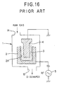
- Japanese Patent Provisional Publication No. 2-70059 discloses an example in which the PLC film forming technology is applied to laboratory tools for coating thereof. An apparatus for forming the DLC film disclosed in the above publication comprises the followings. As shown in FIG. 16, a
cathode 2 is disposed in areaction chamber 1 having aninlet 1A for carbon resource gas which generates carbon or is converted to carbon and anoutlet 1B, and alaboratory tool 3 such as a beaker is accommodated in aspace 2A formed in thecathode 2. Thereaction chamber 1 is decompressed by discharging air from theoutlet 1B after anearthed anode 4 is inserted into an inner space of thelaboratory tool 3. After the carbon resource gas is led into thereaction chamber 1 from theinlet 1A, a high frequency is impressed on thecathode 2 from a highfrequency power source 5 to excite the carbon resource gas, thus generating plasma to form the DLC film on the surfaces of thelaboratory tool 3. - However, in the above DLC film forming apparatus, the
reaction chamber 1 accommodates thecathode 2 and theanode 4, so that the volume of thereaction chamber 1 is remarkably large in comparison with that of thelaboratory tool 3 to be coated. Therefore, it causes wastes of time and energy for a vacuum operation of the reaction chamber. Furthermore, since the film forming speed (rate) in the above DLC film forming apparatus is 10 to 1000Å per minute, which speed is slow, there is a problem in which it is difficult to continuously form the film at a low cost. - The conventional DLC film forming apparatus described above is applied to laboratory tools such as beakers and flasks so as to mainly further increase their qualities, so that the manufacturing cost and time thereof is not much considered. However, containers used for beverages such as beer and orange juice must be manufactured in large quantities at low cost. Accordingly, the DLC film forming apparatus cannot be applied to the containers used for beverages.
- In the above DLC film forming apparatus, since the carbon resource gas moves into the space between the inner surface of the
cathode 2 and the outer surface of thelaboratory tool 3 to be coated, it is impossible to coat only the inner surface of thelaboratory tool 3. - Containers for beverages are often collided and weared with each other in a manufacturing process in a factory or a selling process in a selling route, unlike the laboratory tool such as a beaker and a flask. Therefore, in case that the DLC film is formed on the outer surface of a container for beverages, the DLC film itself is damaged to decrease the value of merchandise of containers because the film is thin and hard. Accordingly, it is required that the DLC film is formed only on the inner surface of the container.
- It is an object of this invention to provide a plastic container coated with carbon film which can solve the problems of gas barrier property and sorption inherently owned by the plastic while maintaining basic properties of plastic, which can be returnably used to extend the fields and the forms in which plastic containers can be used, which can be continuously manufactured at a low cost, and which is not damaged during handling of the containers.
- In order to attain the above object, a plastic container of this invention comprises [a container made of a plastic material with a hard carbon film formed on an inner surface thereof]. In addition, the hard carbon film comprises a diamond like carbon film.
- According to the above plastic container of the invention, permeability of the container against low molecular inorganic gas such as oxygen and carbon dioxide can be remarkably lowered, and furthermore, the sorption in the plastic of various low molecular organic compounds having a smell can be completely suppressed. The formation of the hard carbon film does not deteriorate the transparency of the plastic container.
- The hard carbon film preferably comprises a diamond like carbon film. The diamond like carbon film is a kind of hard carbon film which is called i-carbon film or hydrogenated amorphous carbon film, and is amorphous carbon film mainly including SP3 bond.
- Furthermore, the thickness of the diamond like carbon film is preferably within a range of 0.05-5 µm. With the thickness of the diamond like carbon film limited to the above range, adhesive property of the film to plastic material, the durability and transparency and the like of the container can be obtained, and in addition, the sorption in the plastic of low molecular organic compound can be effectively suppressed and gas barrier property of the container can be improved.
- The following resins are used as plastic material for containers. Polyethylene resin, polypropylene resin, polystyrene resin, cycloolefine copolymer resin, polyethylene terephthalate resin, polyethylene naphthalate resin, ethylene-(vinyl alcohol) copolymer resin, poly-4-methyl pentene-1 resin, poly (methyl methacrylate) resin, acrylonitrile resin, polyvinyl chloride resin, polyvinylidene chloride resin, styrene-acrylonitrile resin, acrylonitrile-butadien-styrene resin, polyamide resin, polyamideimide resin, polyacetal resin, polycarbonate resin, polybutylene terephthalate resin, ionomer resin, polysulfone resin and polytetra fluoroethylene resin.
- When the plastic container with a hard carbon film formed on an inner surface thereof is applied to a bottle for beverages, the plastic container can be returnably used in place of a conventional glass container.
- As described above, the plastic container coated with a hard carbon film of the invention has an excellent gas barrier property and can completely suppress the sorption in the plastic of low molecular organic compound such as odor component, thus making it possible that the container is extensively used as a packaging container in various many fields and as a returnable container capable of refilling therein. Furthermore, since the hard carbon film is formed only on the inner surface of the container in the invention, there is no concern over the damage of the formed hard carbon film during handling of the container.
- In case that the hard carbon film formed on the inner surface of the container comprises a diamond like carbon film, the above-mentioned effects become more remarkable.
-
- FIG. 1 is a longitudinally sectional view showing an embodiment of a manufacturing apparatus for manufacturing a plastic container coated with carbon film according to this invention;
- FIG. 2 is a partially enlarged sectional view of the above embodiment;
- FIG. 3 is a plan view of an insulating plate of the above embodiment;
- FIG. 4 is a longitudinally sectional view showing an embodiment of a plastic container coated with carbon film according to this invention;
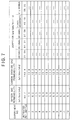
- FIG. 5 is a table showing conditions for forming hard carbon film;
- FIG. 6 is a table showing results evaluating thickness of film and the like of hard carbon film formed under the conditions shown in FIG. 5;
- FIG. 7 is a table showing results evaluating oxygen permeability and the like of the hard carbon film formed under the conditions shown in FIG. 5;
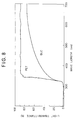
- FIG. 8 is a graph showing transmitted light spectrum in the ultraviolet and visible region of the plastic container with the hard carbon film formed thereon under the conditions shown in FIG. 5;
- FIG. 9 is a graph showing Raman spectrum of the hard carbon film formed under the conditions shown in FIG. 5;
- FIG. 10 is a table showing other conditions for forming the hard carbon film;
- FIG. 11 is a table showing results evaluating thickness and the like of hard carbon film formed under the conditions shown in FIG. 10;
- FIG. 12 is a table showing results evaluating oxygen permeability and the like of the hard carbon film under the conditions shown in FIG. 10;
- FIG. 13 is a table showing further other conditions for forming the hard carbon film;
- FIG. 14 is a table showing results evaluating thickness and the like of the hard carbon film formed under the conditions shown in FIG. 13;
- FIG. 15 is a table showing results evaluating permeability and the like of the hard carbon film formed under the conditions shown in FIG. 13; and
- FIG. 16 is a longitudinally sectional view showing a prior art.
- Embodiments of the invention is explained with reference to drawings.
- FIG. 1 shows a manufacturing apparatus for manufacturing a plastic container coated with carbon film according to the invention. The manufacturing apparatus has a ceramic insulating
plate 11 fixed on abase 10, on which insulating plate anexternal electrode 12 is mounted. Theexternal electrode 12 itself serves at the same time as a vacuum chamber for forming a DLC film, inside of which external electrode a space is formed for accommodating acontainer 20 to be coated. The space formed in theexternal electrode 12 is slightly larger than thecontainer 20 accommodated therein. In this embodiment, thecontainer 20 is a bottle for beverage, however, the container may be used for other objects. - The
external electrode 12 comprises amain body 12A and acover 12B provided detachably on themain body 12A so as to tightly close the interior of themain body 12A. A highfrequency power source 14 is connected to the lower portion of theexternal electrode 12 through amatching device 13 and connectingmembers base 10. Furthermore, a dischargingpipe 15 is communicated as shown in FIG.1 with the space formed in theexternal electrode 12 so as to discharge air in the space by a vacuum pump not shown. - An
internal electrode 16 is inserted into the space of theexternal electrode 12 so as to be disposed at the center portion of the space. The dischargingpipe 15 terminates at the upper surface of the base 10 so as to be opened to acircular space 11B formed at the center portion of the insulatingplate 11. Theinternal electrode 16 is so formed that theelectrode 16 can be inserted into thecontainer 20 through themouth 20A of thecontainer 20, and the external shape of theinternal electrode 16 is approximately similar figures to the internal shape of thecontainer 20. It is preferable that the distance between theexternal electrode 12 and theinternal electrode 16 is kept approximately even at every position of thecontainer 20 within the range of 10 - 150 mm. - A
feed pipe 17 for feeding raw gas is connected with theinternal electrode 16. A raw gas is fed through a gas flow rate controller (not shown) from thefeed pipe 17 for feeding raw gas into theinternal electrode 16. The raw gas thus fed into theinternal electrode 16 blows off from a plurality of blowingopenings 16A formed on theinternal electrode 16. A plurality of blowing openings are preferably formed on the side portion of theinternal electrode 16 as shown in FIG.1 in order to evenly diffuse the blown raw gas. However, in case that the raw gas is evenly diffused immediately after being blown off from theinternal electrode 16, one blowing opening may be formed on the top of theinternal electrode 16. Theinternal electrode 16 is earthed through thefeed pipe 17 for the raw gas. - The insulating
plate 11 comprises a short cylindrical body having an outer circumferential surface and an inner circumferential surface, and has a plurality ofgrooves 11A (four grooves in this embodiment) as enlargedly shown in FIGs. 2 and 3. Each of thegrooves 11A is disposed at an angular interval of 90 ° and the bottom surface of eachgroove 11A is slanted downwardly from an abutting point P (FIG. 2) to the inner circumferential surface of the insulatingplate 11, at which abutting point an inner circumferential surface of theexternal electrode 12 is abutted on the insulatingplate 11. As shown in FIG. 2, anexternal space 21A formed between the inner surface of theexternal electrode 12 and the outer surface of thecontainer 20 is communicated with the dischargingpipe 15 through thegrooves 11A in a state wherein thecontainer 20 is accommodated in theexternal electrode 12 with themouth 20A of thecontainer 20 abutted against the insulatingplate 11. - Then, a method for forming a DLC film by the above manufacturing apparatus is explained.
- The
plastic container 20 is inserted from the upper opening of themain body 12A into theexternal electrode 12 with thecover 12B detached from themain body 12A. At this time, theinternal electrode 16 is inserted into thecontainer 20 through themouth 20A of thecontainer 20. Then, themouth 20A is abutted against the insulatingplate 11 in such manner that theplastic container 20 is placed in an appropriate position in theexternal electrode 12, and thecover 12B then closes the upper opening of themain body 12A so that theexternal electrode 12 is tightly sealed. At this time, the distance between the inner surface of theexternal electrode 12 and the outer surface of thecontainer 20 is maintained approximately even while the distance between the inner surface of thecontainer 20 and the outer surface of theinternal electrode 16 is maintained approximately even. - Thereafter, air in the
external electrode 12 is discharged through the dischargingpipe 15 by a vacuum pump so that the inside of theexternal electrode 12 becomes vacuum. More specifically, theinternal space 21B as well as theexternal space 21A between the outer surface of thecontainer 20 and the inner surface of theexternal electrode 12 becomes vacuum by means of thegrooves 11A formed in the insulatingplate 11. This is because unless theexternal space 21A is vacuum, the temperature in theexternal space 21A becomes remarkably high upon generating plasma, thus affecting the plastic material of thecontainer 20. - The degree of vacuum is preferably within a range from 10-2 to 10-5 torr. With a lower degree of vacuum of over 10-2 torr, impurities in the container are much increased, on the other hand, with a higher degree of vacuum under 10-5 torr, a long time and a large energy are needed to discharge the air in the
container 20. - Then, the raw gas as carbon resource is supplied to the
feed pipe 17 through the gas flow rate controller not shown in the drawing, and then thus supplied raw gas is blown off through theblow openings 16A into theinternal space 21B in the state of vacuum between the outer surface of theinternal electrode 16 and the inner surface of thecontainer 20. The flow rate of the raw gas is preferably within a range from 1 to 100 ml/min, by which flow rate of the raw gas the pressure in theinternal space 21B is adjusted within the range from 0.5 to 0.001 torr. - Since the air in the
external space 21A is discharged through thegrooves 11A, the pressure in theexternal space 21A becomes lower slightly later than the pressure in theinternal space 21B becomes lower. Therefore, when the discharge of the air is just started, the pressure in theexternal space 21A is slightly higher than the pressure in theinternal space 21B. Accordingly, in the case that the supply of the raw gas get started immediately after the discharge of the air in the container is over, the raw gas blown into theinternal space 21B does not get into theexternal space 21A. - Aliphatic hydrocarbons, aromatic hydrocarbons, oxygen containing hydrocarbons, nitrogen containing hydrocarbons, etc., in gaseous or liquid state at a room temperature are used as the raw gas. Especially, benzene, toluene, o-xylene, m-xylene, p-xylene and cyclohexane each having six or more than six carbons are preferable. These raw gases may be used per se, however, mixture of two or more than two kinds of raw gases may be used. Furthermore, these gases may be used in the state of dilution with inert gas such as argon and helium.
- After the supply of the raw gas into the container, electric power is impressed to the
external electrode 12, via thematching device 13, from the high frequencyelectric source 14. The impression of the electric power generates plasma between theexternal electrode 12 andinternal electrode 16. At this moment, theinternal electrode 16 is earthed, however, theexternal electrode 12 is insulated by the insulatingplate 11. Therefore, negative self-bias is generated at theexternal electrode 12. This causes a DLC film to be uniformly formed on the inner surface of thecontainer 20. - More specifically, the formation of the DLC film on the inner surface of the
container 20 is performed by means of an improved plasma CVD method. In case that a low temperature plasma is used in the plasma CVD method, the temperature upon forming the DLC film can be set relatively low. Therefore, the low temperature plasma is suitable in case that an article having a low thermal resistance such as plastic is used as a substrate, and furthermore, the low temperature plasma enables the DLC film to be formed on a wide area at a relatively low cost. - The low temperature plasma is a plasma in the non-equilibrium state in which electron temperature is high in the plasma and temperatures of ion and neutral molecule are remarkably low in comparison with the temperature of the electron in case that the interior of the reaction chamber is maintained at a low pressure.
- When the plasma is generated between the
external electrode 12 and theinternal electrode 16, electrons are accumulated on the inner surface of the insulatedexternal electrode 12 to electrify negatively theexternal electrode 12, namely, to generate negative self-bias on theexternal electrode 12. At theexternal electrode 12, a voltage drop occurs at a range from 500 to 1,000V because of the accumulated electrons. At this time, carbon dioxide as the carbon resource exists in the plasma, and positively ionized carbon resource gas is selectively collided with the inner surface of thecontainer 20 which is disposed along theexternal electrode 12, and, then, carbons close to each other are bonded together thereby to form hard carbon film comprising remarkably dense DLC film on the inner surface of thecontainer 20. The hard carbon film of the DLC film is also called as i-carbon film or hydrogenated amorphous carbon film (a-C:H) and is an amorphous carbon film including mainly SP3 bond. - The thickness of DLC film is varied by an output of high frequency, a pressure of the raw gas in the
container 20, a gas flow rate for feeding, period of time during which plasma is generated, self-bias and kind of raw material and the like. However, the thickness of DLC film is preferably within a range from 0.05 to 5µm to obtain the effective suppression of the sorption of the low molecular organic compound and the improved gas barrier property, in addition to an excellent adhesion to plastic, a good durability and a good transparency. Quality of the DLC film is varied by output of the high frequency, the pressure of the raw gas in thecontainer 20, the gas flow rate, the period of time during which plasma is generated, the self-bias and the kind of raw material in the same manner. Increase of the output of high frequency, decrease of the pressure of the raw gas in thecontainer 20, decrease of the flow rate of the supplied gas, increase of the self-bias, decrease of the carbon number of the raw material and the like cause hardening of the DLC film, increase of the density thereof, increase of the compressive stress thereof and increase of the fragility thereof. Therefore, in order to obtain the maximum sorption suppressing effect to low molecular organic compound and the maximum gas barrier effect while maintaining an excellent adhesion and durability, it is preferable that the output of high frequency is set within a range from 50 to 1,000 W, the pressure of raw gas in thecontainer 20 is set within a range from 0.2 to 0.01 torr, the flow rate of supplied gas is set within a range from 10 to 50 ml/min, the self-bias is set within a range from -200 to -1,000V, and the carbon number is set within a range from 1 to 8. - In order to enhance adhesion between the DLC film and the plastic material, the inner surface of the
container 20 may be activated by plasma treatment with inorganic gas such as argon and oxygen before DLC film is formed. - FIG. 4 shows a longitudinal section of plastic container on which the DLC film is formed in the above manner. In FIG. 4,
numeral numbers plastic material 20a, respectively. In this manner, the plastic container whose inner surface is coated with theDLC film 20b can remarkably decrease permeability of low molecular inorganic gas such as oxygen and carbon dioxide, and simultaneously can completely suppress the sorption of various low molecular organic compounds having odor. Formation of the DLC film does not deteriorate transparency of the plastic container. - The following resins are used as plastic materials for containers 20: polyethylene resin, polypropylene resin, polystyrene resin, cycloolefine copolymer resin, polyethylene terephthalate resin, polyethylene naphthalate resin, ethylene-(vinyl alcohol) copolymer resin, poly-4-methylpentene-1 resin, poly (methyl methacrylate) resin, acrylonitrile resin, polyvinyl chloride resin, polyvinylidene chloride resin, styrene-acrylo nitrile resin, acrylonitrile-butadien-styrene resin, polyamide resin, polyamideimide resin, polyacetal resin, polycarbonate resin, polybutylene terephthalate resin, ionomer resin, polysulfone resin, polytetra fluoroethylene resin and the like.
- With respect to the container coated with carbon film manufactured by the above manufacturing apparatus and method, (1) Thickness of DLC film, (2) Density of DLC film, (3)
Adhesion 1, (4)Adhesion 2, (5) Alkali resistance, (6) Carbon dioxide gas barrier property, (7) Oxygen gas barrier property and (8) Sorption of low molecular organic compound (aroma component) were evaluated in the following manners. The results were as follows: - Masking was previously made by Magic Marker (trade mark) on the inner surface of the container, and the DLC film was then formed. Thereafter, the masking was removed by diethyl ether, and thickness of the DLC film was measured by a surface shape measuring device (DECTACK 3) made by Vecco Company.
- Difference in weight between containers without the DLC film and with the DLC film was measured, and the density of DLC film was calculated with the use of the thickness of the DLC film obtained in item (1).
- Adhesion of the DLC film formed on the side surface of the container was measured in accordance with cross-cut tape test (JIS K 5400) under the following conditions.
- 1. Distance between scratches: 1 mm
- 2. Number of checkers (lattices): 100
- Adhesion of the DLC film formed on the side surface of the container was measured by a continuously weighting type scratch tester (HEIDON 22) made by SHINTO KAGAKU company under the following conditions. Degree of adhesion was indicated by normal load exerted on a scratching needle when the film was started to be peeled off.
- 1. Material and shape of the scratching needle: diamond, 50µR
- 2. Rate of loading: 100g/min
- 3. Table speed: 1,000 mm/min
- Alkali solution including sodium hydroxide of 10 wt% was filled into the container which was then immersed in a water bath at a temperature of 75 °C for 24 hours. Then, change of shape of the DLC film and existence of peeling of the DLC film were investigated. "Excellence" in the table shows that shape of DLC film was not changed and peeling thereof did not occur after the immersion for over 24 hours.
- Volume of carbon dioxide permeating the DLC film was measured by a PERMA TRANC - 4 type machine made by MODERN CONTROL Company at a temperature of 25°C.
- Volume of oxygen permeating the DLC film was measured by an OXTRANTWIN machine made by MODERN CONTROL Company at a temperature of 40°C.
- Low molecular organic compound (aroma component) having odor was used as a kind of environmental material to test the sorption with reference to a method by MATSUI et al. (J. Agri. Food. Chem., 1992, 40, 1902 - 1905) in the following manner.
- 1. Model-flavor solution was prepared in such a manner that each aroma component (n-octane, n-octanal, n-octanol, ethyl hexanoate, and d-limonene) of 100 ppm was added to sugar ester solution to obtain 0.3% sugar ester solution.
- 2. The model flavor solution of 700 ml was poured into the container, the container was left at a temperature of 20 °C for one month after the mouth of the container was closed with the cover.
- 3. One month later, the model flavor solution was removed from the container to dry the interior of the container after the interior thereof was washed with distilled water of 60°C.
- 4. Diethyl ether was poured into the container to extract aroma component sorbed in the container.
- 5. The diethyl ether was taken out of the container to dehydrate the diethyl ether by adding sodium sulfuric anhydride thereto.
- 6. Quantitative analysis was performed by the gas chromatography in which amylbenzene was used as internal standard. In case that solution including aroma component of 1 ppm exists in the container, amount of the aroma component sorbed in the container is indicated by µg. Therefore, unit isµg/ppm/bottle.
- A plastic container having a volume of 700 ml and made of polyethylene terephthalate resin (PET resin, Type L125 made by MITSUI PET RESIN COMPANY LIMITED) was accommodated in the
external electrode 12 as shown in FIG. 1 to be fixed thereto. - Then, the vacuum pump was operated to make the inside of the
external electrode 12 vacuum (back pressure) of lower than 10-4 torr, and, thereafter, for preliminary treatment, argon was supplied into the plastic container at a flow rate of 30 ml/min to obtain a pressure of 0.04 torr in the container, and Rf power of 300W was supplied to perform plasma treatment on the inner surface of the container. Thereafter, raw gas such as toluene, cyclohexane, benzene or p-xylene was supplied into the interior of the container with using argon as auxiliary gas to uniformly form the DLC film on the inner surface of the container under the conditions shown in FIG. 5. - FIG. 6 shows the results of the evaluation with respect to thickness of film, film forming velocity, density of film,
adhesion 1 of film,adhesion 2 of film and alkali resistance of film. The density of each film exceeded 2.00 g/cm3, and the formed film was remarkably dense. - According to the cross-cut test, the adhesion to polyethylene terephthalate resin was good, and it was verified that the container was sufficient to be of practical use. Furthermore, it was found that alkali resistance was good, and the DLC film was stable enough to completely protect the polyethylene terephthalate resin.
- The results of oxygen permeability, carbon dioxide permeability and degree of the sorption of each aroma component are shown in FIG. 7. Dense DLC film completely suppressed the sorption of aroma component, and simultaneously, effectively suppressed permeation of oxygen and carbon dioxide.
- In addition, FIG. 8 shows the transmitted light spectrum in ultraviolet and visible region at the barrel portion of the plastic container, the inner surface of which was coated with the DLC film.
- Light transmittance rate was abruptly decreased in a region from approximately 500 nm of wave length to the ultraviolet region. This suggests that the coating with the use of the DLC film is effective enough to suppress the deterioration of contents by ultraviolet.
- FIG. 9 shows Raman spectrum of the thin film formed on the barrel portion of the plastic container under the conditions of
Test 1. - The DLC film was formed on the inner surface of the container in the same manner as
Test 1 except that a plastic container, having a volume of 700 ml made of styrene-acrylonitrile copolymer resin (made by Mitsubishi Monsant Kasei Company: PAN resin, type L700) was used. The conditions for forming the DLC film are shown in FIG. 10. In the same manner asTest 1, tests were performed in connection with the DLC film, namely, thickness, density,adhesion 1,adhesion 2, alkali resistance, carbon dioxide barrier property, oxygen gas barrier property and sorption of low molecular organic compound. - The results of the test in connection with the DLC film, namely, thickness of film, film forming velocity, density of film,
adhesion 1 of film,adhesion 2 of film and alkali resistance of film were shown in FIG. 11. The thickness of the film and the density thereof were good in the same way asTest 1. It was found that theadhesions Test 1 and the adhesion between the DLC film and the styrene-acrylonitrile copolymer was of practical use in the same way as that between DLC film and polyethylene terephthalate resin. - FIG. 12 shows oxygen permeability, carbon dioxide permeability and degree of sorption of each aroma component. More specifically, it was found that stylene-acrylonitrile copolymer resin was inherently excellent in gas barrier property, and further, the permeating amount of each of oxygen and carbon dioxide with respect to stylene-acrylonitrile copolymer resin was remarkably decreased to an extremely lower level by the formation of the DLC film. Amount of the sorption of each aroma component was smaller than the detectable limit, and there was no problem in sensory test in the same way as
Test 1. - The DLC film was formed on the inner surface of the container in the same manner as
Test 1 except that a plastic container having a volume of 700 ml made of cycloolefine copolymer resin (made by MITSUI PETROCHEMICAL COMPANY LIMITED: COC resin, type APL 6015) was used. The conditions for forming the DLC film are shown in FIG. 13. In the same manner asTest 1, tests were performed in connection with the DLC film, namely, thickness of film, density of film,adhesion 1 of film,adhesion 2 of film, alkali resistance of film, carbon dioxide barrier property of film, oxygen gas barrier property of film and sorption of film to low molecular organic compound. - The results of each test in connection with the DLC film, namely, thickness of film, film forming velocity, density of film,
adhesion 1 of film,adhesion 2 of film, alkali resistance of film are shown in FIG. 14. In the same manner as Tests 1 and 2, there was no problem with respect to all testing items, and, in particular, the adhesion between the DLC film and the plastic container was remarkably excellent. - FIG. 15 shows results of the oxygen permeability of the DLC film, the carbon dioxide permeability thereof and the sorption of each aroma component. Cycloolefine copolymer resin has comparatively large oxygen permeability, carbon dioxide permeability and sorption of aroma components because it is olefine type resin. However, it was found that the formation of the DLC film on the container could considerably suppress the oxygen permeability, the carbon dioxide permeability and the sorption of aroma components.
- The plastic container coated with carbon film of the invention can be used as a returnable container such as a bottle for beer, sake as well as beverage.
Claims (5)
- A container made of a plastic material with a hard carbon film formed on an inner surface thereof.
- A plastic container according to claim 1, wherein said hard carbon film comprises a diamond like carbon film.
- A plastic container according to claim 2, wherein said diamond like carbon film has a thickness of 0.05 to 5µm.
- A plastic container according to claim 1, wherein plastic material forming said container comprises at least one member selected from the group comprising polyethylene resin, polypropylene resin, polystyrene resin, cycloolefine copolymer resin, polyethylene terephthalate resin, polyethylene naphthalate resin, ethylene-(vinyl alcohol) copolymer resin, poly-4-methylpentene-1 resin, poly(methyl methacrylate) resin, acrylonitrile resin, polyvinyl chloride resin, polyvinylidene chloride resin, styrene-acrylonitrile resin, acrylonitrile-butadien-styrene resin, polyamide resin, polyamideimide resin, polyacetal resin, polycarbonate resin, polybutylene terephthalate resin, ionomer resin, polysulfone resin and polytetrafluoroethylene resin.
- A plastic container according to claim 1, wherein said container is a bottle for beverage.
Priority Applications (1)
| Application Number | Priority Date | Filing Date | Title |
|---|---|---|---|
| EP02012807A EP1254845A3 (en) | 1994-08-11 | 1995-08-09 | Plastic container coated with carbon film |
Applications Claiming Priority (4)
| Application Number | Priority Date | Filing Date | Title |
|---|---|---|---|
| JP189223/94 | 1994-08-11 | ||
| JP18922394 | 1994-08-11 | ||
| JP6189223A JPH0853116A (en) | 1994-08-11 | 1994-08-11 | Plastic container coated with carbon film |
| PCT/JP1995/001582 WO1996005111A1 (en) | 1994-08-11 | 1995-08-09 | Carbon film-coated plastic container |
Related Child Applications (1)
| Application Number | Title | Priority Date | Filing Date |
|---|---|---|---|
| EP02012807A Division EP1254845A3 (en) | 1994-08-11 | 1995-08-09 | Plastic container coated with carbon film |
Publications (3)
| Publication Number | Publication Date |
|---|---|
| EP0773166A1 true EP0773166A1 (en) | 1997-05-14 |
| EP0773166A4 EP0773166A4 (en) | 1999-08-25 |
| EP0773166B1 EP0773166B1 (en) | 2002-11-27 |
Family
ID=16237641
Family Applications (2)
| Application Number | Title | Priority Date | Filing Date |
|---|---|---|---|
| EP95927996A Expired - Lifetime EP0773166B1 (en) | 1994-08-11 | 1995-08-09 | Diamond-like carbon film-coated plastic container |
| EP02012807A Withdrawn EP1254845A3 (en) | 1994-08-11 | 1995-08-09 | Plastic container coated with carbon film |
Family Applications After (1)
| Application Number | Title | Priority Date | Filing Date |
|---|---|---|---|
| EP02012807A Withdrawn EP1254845A3 (en) | 1994-08-11 | 1995-08-09 | Plastic container coated with carbon film |
Country Status (11)
| Country | Link |
|---|---|
| US (3) | US6589619B1 (en) |
| EP (2) | EP0773166B1 (en) |
| JP (2) | JPH0853116A (en) |
| KR (1) | KR100398742B1 (en) |
| AT (1) | ATE228462T1 (en) |
| CA (1) | CA2196888C (en) |
| DE (1) | DE69528982T2 (en) |
| DK (1) | DK0773166T3 (en) |
| MY (1) | MY155224A (en) |
| TW (1) | TW316929B (en) |
| WO (1) | WO1996005111A1 (en) |
Cited By (18)
| Publication number | Priority date | Publication date | Assignee | Title |
|---|---|---|---|---|
| US5853833A (en) * | 1996-05-20 | 1998-12-29 | Daikyo Seiko, Ltd. | Sanitary container and production process thereof |
| FR2776540A1 (en) * | 1998-03-27 | 1999-10-01 | Sidel Sa | BARRIER-EFFECT CONTAINER AND PROCESS AND APPARATUS FOR ITS MANUFACTURING |
| EP1124729A1 (en) * | 1999-08-06 | 2001-08-22 | Plastipak Packaging, Inc. | Plastic container having a carbon-treated internal surface |
| EP1220281A2 (en) * | 2000-12-25 | 2002-07-03 | Toyo Seikan Kaisya, Ltd. | Method of treatment with a microwave plasma |
| EP1229068A1 (en) * | 2001-02-06 | 2002-08-07 | Shibuya Kogyo Co., Ltd. | Method and apparatus for modifying the inner surface of containers made of polymeric compound |
| US6461699B1 (en) | 2000-10-06 | 2002-10-08 | Plastipak Packaging, Inc. | Plastic container having a carbon-treated internal surface for non-carbonated food products |
| US6495226B1 (en) | 1999-08-06 | 2002-12-17 | Plastipak Packaging, Inc. | Plastic container having a carbon-treated internal surface |
| DE10129951A1 (en) * | 2001-06-21 | 2003-01-09 | Fleming Claudia | Manufacture of diffusion-resistant plastic hose, especially for air conditioning systems on vehicles, involves filling it with ignitable gas and igniting it with a corona discharge |
| WO2004012999A2 (en) | 2002-08-02 | 2004-02-12 | Plastipak Packaging, Inc. | Ultraviolet bottle coating thickness measurement |
| EP1438444A2 (en) * | 2001-10-25 | 2004-07-21 | NTTF GmbH | Mechanically and thermodynamically stable amorphous carbon layers for temperature-sensitive surfaces |
| US6822391B2 (en) | 2001-02-21 | 2004-11-23 | Semiconductor Energy Laboratory Co., Ltd. | Light emitting device, electronic equipment, and method of manufacturing thereof |
| AT413109B (en) * | 2004-05-28 | 2005-11-15 | Gruber Karl Dipl Ing Dr | DIAMOND ELECTRODE ON PLASTIC BASE |
| US7005671B2 (en) | 2001-10-01 | 2006-02-28 | Semiconductor Energy Laboratory Co., Ltd. | Light emitting device, electronic equipment, and organic polarizing film |
| US7067976B2 (en) | 2001-07-03 | 2006-06-27 | Semiconductor Energy Laboratory Co., Ltd. | Light-emitting device, method of manufacturing a light-emitting device, and electronic equipment |
| WO2007035741A2 (en) * | 2005-09-20 | 2007-03-29 | Dow Global Technologies Inc. | Process for plasma assisted coating a nanocomposite object |
| US7465482B2 (en) | 2001-10-10 | 2008-12-16 | Semiconductor Energy Laboratory Co., Ltd. | Film, packaging material, container, lens, window, spectacles, recording medium, and deposition apparatus |
| AT414338B1 (en) * | 2004-05-28 | 2010-03-15 | Gruber Karl Dr | ELECTROLYTE CLEANING METHOD WITH BIPOLAR PLASTIC DIAMOND ELECTRODES |
| WO2010095011A1 (en) * | 2009-02-18 | 2010-08-26 | Council Of Scientific & Industrial Research | Process to deposit diamond like carbon as protective coating on inner surface of a shaped object. |
Families Citing this family (49)
| Publication number | Priority date | Publication date | Assignee | Title |
|---|---|---|---|---|
| JPH0853116A (en) * | 1994-08-11 | 1996-02-27 | Kirin Brewery Co Ltd | Plastic container coated with carbon film |
| JP3637687B2 (en) * | 1996-07-13 | 2005-04-13 | 日新電機株式会社 | Manufacturing method of diaphragm for automobile |
| US6893720B1 (en) | 1997-06-27 | 2005-05-17 | Nissin Electric Co., Ltd. | Object coated with carbon film and method of manufacturing the same |
| JP3024751B2 (en) | 1998-04-22 | 2000-03-21 | 日本電気株式会社 | Frame offset setting system, setting method, and setting program recording medium |
| EP1197581B1 (en) | 1999-05-19 | 2006-10-25 | Mitsubishi Shoji Plastics Corporation | Dlc film, dlc-coated plastic container, and method and apparatus for manufacturing dlc-coated plastic container |
| JP2001139075A (en) * | 1999-11-15 | 2001-05-22 | Hokkai Can Co Ltd | Aerosol container |
| AU2403001A (en) * | 1999-12-27 | 2001-07-09 | Mitsubishi Shoji Plastics Corporation | Pet container for foods and drinks containing recycled resin and having dlc coating film formed on surface thereof |
| JP4492985B2 (en) | 2000-02-24 | 2010-06-30 | 三菱商事プラスチック株式会社 | Liquid medicine plastic container and liquid medicine storage and recovery method |
| JP2001240115A (en) * | 2000-02-24 | 2001-09-04 | Mitsubishi Shoji Plast Kk | Plastic container for dry solid food |
| JP2001240034A (en) * | 2000-02-24 | 2001-09-04 | Mitsubishi Shoji Plast Kk | Plastic container for liquid containing volatile organic substance |
| JP3952695B2 (en) * | 2000-05-26 | 2007-08-01 | 学校法人金沢工業大学 | Method and apparatus for surface modification of polymer compound container |
| JP2002002649A (en) * | 2000-06-27 | 2002-01-09 | Hokkai Can Co Ltd | Polyethylene terephthalate resin container |
| FR2812665B1 (en) * | 2000-08-01 | 2003-08-08 | Sidel Sa | PLASMA COATING DEPOSITION METHOD, DEVICE FOR IMPLEMENTING THE METHOD AND COATING OBTAINED BY SUCH A PROCESS |
| JP3993971B2 (en) * | 2000-08-09 | 2007-10-17 | 北海製罐株式会社 | Plastic container having gas barrier coating layer and method for producing the same |
| WO2002085717A1 (en) * | 2001-04-19 | 2002-10-31 | Nissei Asb Machine Co., Ltd. | Gas-barrier synthetic resin vessel, device for producing the same, and article-received gas-barrier synthetic resin vessel |
| JP2003104386A (en) * | 2001-09-28 | 2003-04-09 | Toppan Printing Co Ltd | Plastic container coated with ceramic |
| WO2003086878A1 (en) * | 2002-04-15 | 2003-10-23 | Mitsubishi Shoji Plastics Corporation | System and method for forming dlc film on inner surface of plastic container |
| WO2003091121A1 (en) * | 2002-04-26 | 2003-11-06 | Hokkai Can Co., Ltd. | Plastic containers coated on the inner surface and process for production thereof |
| ATE506270T1 (en) * | 2002-05-28 | 2011-05-15 | Kirin Brewery | DEVICE FOR COATING A PLASTIC CONTAINER WITH A DIAMOND-LIKE CARBON LAYER |
| JP3699474B2 (en) * | 2003-02-28 | 2005-09-28 | 鹿毛 剛 | Gas barrier property measurement method for plastic moldings |
| JP4437647B2 (en) * | 2003-07-17 | 2010-03-24 | 三菱商事プラスチック株式会社 | Method for producing gas container coated plastic container |
| JP3826933B2 (en) | 2003-10-24 | 2006-09-27 | 東洋インキ製造株式会社 | Colorant for thermoplastic resin and use thereof |
| FR2872148B1 (en) * | 2004-06-24 | 2006-09-22 | Sidel Sas | BOTTLE PROCESSING MACHINE EQUIPPED WITH AN INTERCHANGEABLE CONNECTION CARTRIDGE |
| JP2006064416A (en) * | 2004-08-24 | 2006-03-09 | Takeshi Kage | Method and apparatus for measuring gas barrier property of plastic molded body |
| JP2006089073A (en) * | 2004-09-22 | 2006-04-06 | Hokkai Can Co Ltd | Internally coated plastic container and method for manufacturing the same |
| JP4171452B2 (en) | 2004-10-18 | 2008-10-22 | 三菱重工食品包装機械株式会社 | Barrier film forming internal electrode and film forming apparatus |
| JP4725093B2 (en) * | 2004-12-10 | 2011-07-13 | 東洋製罐株式会社 | Microwave processing equipment |
| US7352584B1 (en) | 2005-05-10 | 2008-04-01 | Chien-Min Sung | Diamond-like carbon coated devices |
| JP4883590B2 (en) * | 2006-03-17 | 2012-02-22 | 独立行政法人産業技術総合研究所 | Laminated body and carbon film deposition method |
| US20100211180A1 (en) * | 2006-03-21 | 2010-08-19 | Jet Engineering, Inc. | Tetrahedral Amorphous Carbon Coated Medical Devices |
| KR101414420B1 (en) | 2006-11-22 | 2014-07-01 | 엔테그리스, 아이엔씨. | Diamond like carbon coating of substrate housing |
| EP2094466B1 (en) * | 2006-12-21 | 2011-05-25 | Alpla-Werke Alwin Lehner GmbH und Co.KG | Formulation, preform produced thereof, and method for the production of stretch blow-molded opaque plastic containers |
| US20080202414A1 (en) * | 2007-02-23 | 2008-08-28 | General Electric Company | Methods and devices for coating an interior surface of a plastic container |
| JP5355860B2 (en) | 2007-03-16 | 2013-11-27 | 三菱重工食品包装機械株式会社 | Barrier film forming apparatus, barrier film forming method, and barrier film coating container |
| CN101678920B (en) * | 2007-06-06 | 2011-05-11 | 东洋制罐株式会社 | Biodegradable resin bottle and process for producing the same |
| US8950614B2 (en) * | 2007-08-14 | 2015-02-10 | Toyo Seikan Kaisha, Ltd. | Biodegradable resin container with a vacuum-evaporated film and method of forming a vacuum-evaporated film |
| JP2009127059A (en) * | 2007-11-20 | 2009-06-11 | Tokyo Denki Univ | Method for forming diamond-like carbon film |
| JP5735744B2 (en) * | 2008-01-31 | 2015-06-17 | 日本山村硝子株式会社 | Cap and container equipped with the cap |
| WO2009119549A1 (en) * | 2008-03-27 | 2009-10-01 | 東洋製罐株式会社 | Stretched foam plastic container and process for producing the stretched foam plastic container |
| JP5122386B2 (en) * | 2008-07-09 | 2013-01-16 | 株式会社ダン・タクマ | Case for semiconductor |
| US20110001103A1 (en) * | 2009-07-01 | 2011-01-06 | Chi-Kuang Chen | Elevating mechanism for measuring concentrations of medicines |
| SG191213A1 (en) | 2010-12-28 | 2013-07-31 | Kirin Brewery | Gas-barrier plastic molded product and manufacturing process therefor |
| JP5610536B2 (en) * | 2011-03-17 | 2014-10-22 | 麒麟麦酒株式会社 | Coated plastic molded body and method for producing the same |
| US9404334B2 (en) | 2012-08-31 | 2016-08-02 | Baker Hughes Incorporated | Downhole elastomeric components including barrier coatings |
| EP3114250B1 (en) * | 2014-03-03 | 2024-05-01 | Picosun Oy | Protecting an interior of a gas container with an ald coating |
| JP6394050B2 (en) * | 2014-05-07 | 2018-09-26 | 凸版印刷株式会社 | Packaging container with function to prevent odor residue |
| JP6819119B2 (en) * | 2016-07-26 | 2021-01-27 | 三菱ケミカル株式会社 | A container made of polyethylene terephthalate with a gas barrier membrane |
| US10894625B1 (en) | 2020-07-29 | 2021-01-19 | Verre Vert, Inc. | Lightweight polymer bottle for wine and spirits |
| CN115384033A (en) * | 2022-09-20 | 2022-11-25 | 湖南千山制药机械股份有限公司 | Plastic container internal plating module, injection blow-plating all-in-one machine and injection blow-plating encapsulation all-in-one machine |
Citations (8)
| Publication number | Priority date | Publication date | Assignee | Title |
|---|---|---|---|---|
| WO1984001352A1 (en) * | 1982-09-29 | 1984-04-12 | Nat Can Corp | Multiwalled container and method of making same |
| US4699809A (en) * | 1981-11-05 | 1987-10-13 | Toyo Seikan Kaisha, Ltd. | Process for preparation of coated oriented plastic container |
| US4809876A (en) * | 1987-08-27 | 1989-03-07 | Aluminum Company Of America | Container body having improved gas barrier properties |
| US5255783A (en) * | 1991-12-20 | 1993-10-26 | Fluoroware, Inc. | Evacuated wafer container |
| WO1993024243A1 (en) * | 1992-05-28 | 1993-12-09 | Polar Materials, Inc. | Methods and apparatus for depositing barrier coatings |
| WO1994000247A1 (en) * | 1992-06-26 | 1994-01-06 | Polar Materials, Inc. | Methods and apparatus for externally treating a container with application of internal bias gas |
| EP0580094A1 (en) * | 1992-07-22 | 1994-01-26 | Becton, Dickinson and Company | Blood collection assembly |
| WO1994011544A1 (en) * | 1992-11-13 | 1994-05-26 | Energy Conversion Devices, Inc. | Microwave apparatus for depositing thin films |
Family Cites Families (33)
| Publication number | Priority date | Publication date | Assignee | Title |
|---|---|---|---|---|
| JPS5981126A (en) | 1983-08-24 | 1984-05-10 | Hitachi Ltd | Manufacture of resin mold product |
| JPS60228250A (en) * | 1984-04-24 | 1985-11-13 | テルモ株式会社 | Vessel made of synthetic resin and manufacture thereof |
| FR2592874B1 (en) * | 1986-01-14 | 1990-08-03 | Centre Nat Rech Scient | PROCESS FOR DIPPING A GLASS OR VITREOUS OBJECT AND OBJECT THUS DIPPED |
| US4725464A (en) * | 1986-05-30 | 1988-02-16 | Continental Pet Technologies, Inc. | Refillable polyester beverage bottle and preform for forming same |
| US4756964A (en) * | 1986-09-29 | 1988-07-12 | The Dow Chemical Company | Barrier films having an amorphous carbon coating and methods of making |
| JPH0676666B2 (en) * | 1987-02-10 | 1994-09-28 | 株式会社半導体エネルギ−研究所 | Carbon film production method |
| JPH01100277A (en) * | 1987-10-12 | 1989-04-18 | Idemitsu Petrochem Co Ltd | Curved plate stuck with rigid carbonaceous film, manufacture and manufacturing device thereof |
| JPH0270059A (en) * | 1987-12-02 | 1990-03-08 | Idemitsu Petrochem Co Ltd | Appliance and its production |
| JPH0627342B2 (en) * | 1988-02-05 | 1994-04-13 | 株式会社半導体エネルギー研究所 | Carbon film formation method |
| JPH02138469A (en) * | 1988-11-16 | 1990-05-28 | Hitachi Ltd | Material for vacuum having diamond surface, surface treatment of this material for vacuum production, of diamond film surface, vacuum vessel and its parts formed by using material for vacuum, in-vacuum driving mechanism, electron release source, in-vacuum heater and vessel of vapor deposition source |
| JPH02144574A (en) * | 1988-11-25 | 1990-06-04 | Toshiba Corp | Electrophotographic system printer device |
| JPH0744623Y2 (en) | 1989-05-08 | 1995-10-11 | 石塚硝子株式会社 | Bottle container with antibacterial properties |
| JPH03130363A (en) * | 1989-10-16 | 1991-06-04 | Nikon Corp | Plastic articles coated with diamond-like carbon film |
| JPH04304373A (en) * | 1991-03-29 | 1992-10-27 | Shimadzu Corp | Formation of hard carbon film |
| JPH04331917A (en) * | 1991-05-07 | 1992-11-19 | Ricoh Co Ltd | Liquid crystal display device |
| JPH0535660A (en) | 1991-07-31 | 1993-02-12 | Toshiba Corp | Signal processor |
| JP2579128Y2 (en) * | 1991-10-17 | 1998-08-20 | 共同印刷株式会社 | Small plastic containers |
| JP3017602B2 (en) * | 1992-05-27 | 2000-03-13 | 日精エー・エス・ビー機械株式会社 | Refillable plastic container |
| US5628957A (en) * | 1992-07-07 | 1997-05-13 | Continental Pet Technologies, Inc. | Method of forming multilayer container with polyethylene naphthalalte (pen) |
| JPH0644558A (en) * | 1992-07-24 | 1994-02-18 | Matsushita Electric Ind Co Ltd | Magnetic recording medium |
| US5346600A (en) * | 1992-08-14 | 1994-09-13 | Hughes Aircraft Company | Plasma-enhanced magnetron-sputtered deposition of materials |
| US5318806A (en) * | 1992-10-02 | 1994-06-07 | Becton, Dickinson And Company | Tube having regions of different surface chemistry and method therefor |
| JPH0853116A (en) * | 1994-08-11 | 1996-02-27 | Kirin Brewery Co Ltd | Plastic container coated with carbon film |
| JP2788412B2 (en) * | 1994-08-11 | 1998-08-20 | 麒麟麦酒株式会社 | Apparatus and method for producing carbon film-coated plastic container |
| US5521351A (en) * | 1994-08-30 | 1996-05-28 | Wisconsin Alumni Research Foundation | Method and apparatus for plasma surface treatment of the interior of hollow forms |
| US5529815A (en) * | 1994-11-03 | 1996-06-25 | Lemelson; Jerome H. | Apparatus and method for forming diamond coating |
| US5693376A (en) * | 1995-06-23 | 1997-12-02 | Wisconsin Alumni Research Foundation | Method for plasma source ion implantation and deposition for cylindrical surfaces |
| US5702770A (en) * | 1996-01-30 | 1997-12-30 | Becton, Dickinson And Company | Method for plasma processing |
| JP3176558B2 (en) * | 1996-02-09 | 2001-06-18 | 麒麟麦酒株式会社 | Coating film and method for producing the same |
| US5707691A (en) * | 1996-08-27 | 1998-01-13 | The Coca-Cola Company | Coating hollow containers by in-situ polymerization of monomers in bi-axially orientated form |
| EP1010773A4 (en) * | 1997-02-19 | 2004-08-25 | Kirin Brewery | Method and apparatus for producing plastic container having carbon film coating |
| JP2000015770A (en) * | 1998-06-30 | 2000-01-18 | Think Laboratory Co Ltd | Method for reusing printing plate |
| WO2002085717A1 (en) * | 2001-04-19 | 2002-10-31 | Nissei Asb Machine Co., Ltd. | Gas-barrier synthetic resin vessel, device for producing the same, and article-received gas-barrier synthetic resin vessel |
-
1994
- 1994-08-11 JP JP6189223A patent/JPH0853116A/en active Pending
-
1995
- 1995-07-11 KR KR1019950020268A patent/KR100398742B1/en not_active IP Right Cessation
- 1995-07-15 TW TW084107388A patent/TW316929B/zh not_active IP Right Cessation
- 1995-08-09 DK DK95927996T patent/DK0773166T3/en active
- 1995-08-09 CA CA002196888A patent/CA2196888C/en not_active Expired - Fee Related
- 1995-08-09 US US08/776,702 patent/US6589619B1/en not_active Expired - Fee Related
- 1995-08-09 AT AT95927996T patent/ATE228462T1/en active
- 1995-08-09 EP EP95927996A patent/EP0773166B1/en not_active Expired - Lifetime
- 1995-08-09 DE DE69528982T patent/DE69528982T2/en not_active Expired - Lifetime
- 1995-08-09 WO PCT/JP1995/001582 patent/WO1996005111A1/en active IP Right Grant
- 1995-08-09 EP EP02012807A patent/EP1254845A3/en not_active Withdrawn
- 1995-08-11 MY MYPI95002346A patent/MY155224A/en unknown
-
2000
- 2000-03-13 JP JP2000073951A patent/JP3545305B2/en not_active Expired - Lifetime
-
2003
- 2003-06-03 US US10/452,213 patent/US6805931B2/en not_active Expired - Fee Related
- 2003-06-03 US US10/452,208 patent/US20030207115A1/en not_active Abandoned
Patent Citations (8)
| Publication number | Priority date | Publication date | Assignee | Title |
|---|---|---|---|---|
| US4699809A (en) * | 1981-11-05 | 1987-10-13 | Toyo Seikan Kaisha, Ltd. | Process for preparation of coated oriented plastic container |
| WO1984001352A1 (en) * | 1982-09-29 | 1984-04-12 | Nat Can Corp | Multiwalled container and method of making same |
| US4809876A (en) * | 1987-08-27 | 1989-03-07 | Aluminum Company Of America | Container body having improved gas barrier properties |
| US5255783A (en) * | 1991-12-20 | 1993-10-26 | Fluoroware, Inc. | Evacuated wafer container |
| WO1993024243A1 (en) * | 1992-05-28 | 1993-12-09 | Polar Materials, Inc. | Methods and apparatus for depositing barrier coatings |
| WO1994000247A1 (en) * | 1992-06-26 | 1994-01-06 | Polar Materials, Inc. | Methods and apparatus for externally treating a container with application of internal bias gas |
| EP0580094A1 (en) * | 1992-07-22 | 1994-01-26 | Becton, Dickinson and Company | Blood collection assembly |
| WO1994011544A1 (en) * | 1992-11-13 | 1994-05-26 | Energy Conversion Devices, Inc. | Microwave apparatus for depositing thin films |
Non-Patent Citations (2)
| Title |
|---|
| PATENT ABSTRACTS OF JAPAN vol. 014, no. 254 (C-0724), 31 May 1990 & JP 02 070059 A (IDEMITSU PETROCHEM CO LTD), 8 March 1990 * |
| See also references of WO9605111A1 * |
Cited By (39)
| Publication number | Priority date | Publication date | Assignee | Title |
|---|---|---|---|---|
| US5853833A (en) * | 1996-05-20 | 1998-12-29 | Daikyo Seiko, Ltd. | Sanitary container and production process thereof |
| FR2776540A1 (en) * | 1998-03-27 | 1999-10-01 | Sidel Sa | BARRIER-EFFECT CONTAINER AND PROCESS AND APPARATUS FOR ITS MANUFACTURING |
| WO1999049991A1 (en) * | 1998-03-27 | 1999-10-07 | Sidel | Container with material coating having barrier effect and method and apparatus for making same |
| FR2783667A1 (en) * | 1998-03-27 | 2000-03-24 | Sidel Sa | Plasma deposition equipment coats PET bottle with internal carbon layer from gaseous precursor in microwave field, overcoming numerous shortcomings of known barrier layer alternatives |
| CZ299306B6 (en) * | 1998-03-27 | 2008-06-11 | Sidel | Container with a coating of barrier effect material, and process and apparatus for manufacturing the same |
| US6919114B1 (en) | 1998-03-27 | 2005-07-19 | Sidel | Container with material coating having barrier effect and method and apparatus for making same |
| US6827972B2 (en) | 1998-03-27 | 2004-12-07 | Sidel | Container with a coating of barrier effect material, and method and apparatus for manufacturing the same |
| CN1796005B (en) * | 1999-08-06 | 2010-09-15 | 普拉斯蒂派克包装公司 | Plastic container having a carbon-treated internal surface |
| EP1124729A1 (en) * | 1999-08-06 | 2001-08-22 | Plastipak Packaging, Inc. | Plastic container having a carbon-treated internal surface |
| US6495226B1 (en) | 1999-08-06 | 2002-12-17 | Plastipak Packaging, Inc. | Plastic container having a carbon-treated internal surface |
| EP1124729A4 (en) * | 1999-08-06 | 2004-12-01 | Plastipak Packaging Inc | Plastic container having a carbon-treated internal surface |
| US6592956B2 (en) | 1999-08-06 | 2003-07-15 | Plastipak Packaging, Inc. | Plastic container having a carbon-treated internal surface |
| EP1324876A1 (en) * | 2000-10-06 | 2003-07-09 | Plastipak Packaging, Inc. | Plastic container having a carbon-treated internal surface for non-carbonated food products |
| US6461699B1 (en) | 2000-10-06 | 2002-10-08 | Plastipak Packaging, Inc. | Plastic container having a carbon-treated internal surface for non-carbonated food products |
| EP1324876A4 (en) * | 2000-10-06 | 2004-12-08 | Plastipak Packaging Inc | Plastic container having a carbon-treated internal surface for non-carbonated food products |
| EP1220281B1 (en) * | 2000-12-25 | 2012-02-01 | Toyo Seikan Kaisha, Ltd. | Method of treatment with a microwave plasma |
| EP1220281A2 (en) * | 2000-12-25 | 2002-07-03 | Toyo Seikan Kaisya, Ltd. | Method of treatment with a microwave plasma |
| EP1229068A1 (en) * | 2001-02-06 | 2002-08-07 | Shibuya Kogyo Co., Ltd. | Method and apparatus for modifying the inner surface of containers made of polymeric compound |
| US6822391B2 (en) | 2001-02-21 | 2004-11-23 | Semiconductor Energy Laboratory Co., Ltd. | Light emitting device, electronic equipment, and method of manufacturing thereof |
| US7443097B2 (en) | 2001-02-21 | 2008-10-28 | Semiconductor Energy Laboratory Co., Ltd. | Light emitting device and electronic equipment |
| US6956325B2 (en) | 2001-02-21 | 2005-10-18 | Semiconductor Energy Laboratory Co., Ltd. | Light-emitting device, electronic equipment, and method of manufacturing thereof |
| DE10129951A1 (en) * | 2001-06-21 | 2003-01-09 | Fleming Claudia | Manufacture of diffusion-resistant plastic hose, especially for air conditioning systems on vehicles, involves filling it with ignitable gas and igniting it with a corona discharge |
| US7372200B2 (en) | 2001-07-03 | 2008-05-13 | Semiconductor Energy Laboratory Co., Ltd. | Light-emitting device, method of manufacturing a light-emitting device, and electronic equipment |
| US7067976B2 (en) | 2001-07-03 | 2006-06-27 | Semiconductor Energy Laboratory Co., Ltd. | Light-emitting device, method of manufacturing a light-emitting device, and electronic equipment |
| US7129102B2 (en) | 2001-07-03 | 2006-10-31 | Semiconductor Energy Laboratory Co., Ltd. | Light-emitting device, method of manufacturing a light-emitting device, and electronic equipment |
| US7800099B2 (en) | 2001-10-01 | 2010-09-21 | Semiconductor Energy Laboratory Co., Ltd. | Light emitting device, electronic equipment, and organic polarizing film |
| US7005671B2 (en) | 2001-10-01 | 2006-02-28 | Semiconductor Energy Laboratory Co., Ltd. | Light emitting device, electronic equipment, and organic polarizing film |
| US7465482B2 (en) | 2001-10-10 | 2008-12-16 | Semiconductor Energy Laboratory Co., Ltd. | Film, packaging material, container, lens, window, spectacles, recording medium, and deposition apparatus |
| EP1438444A2 (en) * | 2001-10-25 | 2004-07-21 | NTTF GmbH | Mechanically and thermodynamically stable amorphous carbon layers for temperature-sensitive surfaces |
| EP1542905A4 (en) * | 2002-08-02 | 2008-05-21 | Plastipak Packaging Inc | Process and apparatus for testing bottles |
| WO2004012999A2 (en) | 2002-08-02 | 2004-02-12 | Plastipak Packaging, Inc. | Ultraviolet bottle coating thickness measurement |
| EP1542905A2 (en) * | 2002-08-02 | 2005-06-22 | Plastipak Packaging, Inc. | Process and apparatus for testing bottles |
| AT414338B1 (en) * | 2004-05-28 | 2010-03-15 | Gruber Karl Dr | ELECTROLYTE CLEANING METHOD WITH BIPOLAR PLASTIC DIAMOND ELECTRODES |
| AT413109B (en) * | 2004-05-28 | 2005-11-15 | Gruber Karl Dipl Ing Dr | DIAMOND ELECTRODE ON PLASTIC BASE |
| WO2007035741A3 (en) * | 2005-09-20 | 2007-05-24 | Dow Global Technologies Inc | Process for plasma assisted coating a nanocomposite object |
| WO2007035741A2 (en) * | 2005-09-20 | 2007-03-29 | Dow Global Technologies Inc. | Process for plasma assisted coating a nanocomposite object |
| WO2010095011A1 (en) * | 2009-02-18 | 2010-08-26 | Council Of Scientific & Industrial Research | Process to deposit diamond like carbon as protective coating on inner surface of a shaped object. |
| EP2589680A1 (en) * | 2009-02-18 | 2013-05-08 | Council of Scientific & Industrial Research | Apparatus for the deposition of diamondlike carbon as protective coating on an inner surface of a shaped object |
| US9260781B2 (en) | 2009-02-18 | 2016-02-16 | Council Of Scientific And Industrial Research | Process to deposit diamond like carbon as surface of a shaped object |
Also Published As
| Publication number | Publication date |
|---|---|
| CA2196888C (en) | 2005-06-07 |
| JP3545305B2 (en) | 2004-07-21 |
| DE69528982T2 (en) | 2003-08-28 |
| DK0773166T3 (en) | 2003-03-17 |
| CA2196888A1 (en) | 1996-02-22 |
| WO1996005111A1 (en) | 1996-02-22 |
| EP0773166B1 (en) | 2002-11-27 |
| US6589619B1 (en) | 2003-07-08 |
| ATE228462T1 (en) | 2002-12-15 |
| US6805931B2 (en) | 2004-10-19 |
| JP2000309324A (en) | 2000-11-07 |
| JPH0853116A (en) | 1996-02-27 |
| US20030203143A1 (en) | 2003-10-30 |
| MY155224A (en) | 2015-09-30 |
| TW316929B (en) | 1997-10-01 |
| KR960007662A (en) | 1996-03-22 |
| US20030207115A1 (en) | 2003-11-06 |
| EP1254845A3 (en) | 2006-02-15 |
| EP0773166A4 (en) | 1999-08-25 |
| KR100398742B1 (en) | 2003-12-11 |
| EP1254845A2 (en) | 2002-11-06 |
| DE69528982D1 (en) | 2003-01-09 |
Similar Documents
| Publication | Publication Date | Title |
|---|---|---|
| CA2196888C (en) | Plastic container coated with carbon film | |
| EP0773167B1 (en) | Carbon film-coated plastic container manufacturing apparatus and method | |
| US20020006487A1 (en) | Transmission barrier layer for polymers and containers | |
| US5919328A (en) | Blood collection tube assembly | |
| EP0051443B1 (en) | Laminated plastic container and process for preparation thereof | |
| US20030215652A1 (en) | Transmission barrier layer for polymers and containers | |
| JP2004504938A (en) | Plasma-deposited barrier coating with a boundary layer, method for obtaining such a coating, and a container thus obtained | |
| EP0787825A1 (en) | Blood collection tube assembly | |
| EP0794007A1 (en) | Blood collection tube assembly | |
| KR100457637B1 (en) | Coating film and its manufacturing method | |
| GB2151262A (en) | Methods for improving the gas barrier properties of polymeric containers | |
| EP1197581A1 (en) | Dlc film, dlc-coated plastic container, and method and apparatus for manufacturing dlc-coated plastic container | |
| EP1542905A2 (en) | Process and apparatus for testing bottles | |
| JPH11348171A (en) | Transparent barrier film and laminated body using same | |
| JP4050649B2 (en) | How to use bottles for carbon film coating beverages | |
| JP2008069407A (en) | Method for producing polylactic acid molding | |
| JP4050648B2 (en) | Carbon film coated beverage bottle | |
| JP2001158415A (en) | Plastic bottle for atmospheric low temperature plasma treatment and its manufacturing method | |
| JP2003327248A (en) | Manufacturing method of beverage bottle coated with carbon film | |
| JPH11105189A (en) | Transparent barrier nylon film, and laminated body and container for package using it | |
| JP2004168325A (en) | Plastic container with barrier property | |
| JP3864126B2 (en) | Inner coated polyester resin container |
Legal Events
| Date | Code | Title | Description |
|---|---|---|---|
| PUAI | Public reference made under article 153(3) epc to a published international application that has entered the european phase |
Free format text: ORIGINAL CODE: 0009012 |
|
| 17P | Request for examination filed |
Effective date: 19970303 |
|
| AK | Designated contracting states |
Kind code of ref document: A1 Designated state(s): AT BE CH DE DK FR GB IT LI NL SE |
|
| A4 | Supplementary search report drawn up and despatched |
Effective date: 19990713 |
|
| AK | Designated contracting states |
Kind code of ref document: A4 Designated state(s): AT BE CH DE DK FR GB IT LI NL SE |
|
| RIC1 | Information provided on ipc code assigned before grant |
Free format text: 6B 65D 1/00 A, 6B 65D 23/02 B, 6C 23C 16/04 B, 6C 23C 16/26 B |
|
| 17Q | First examination report despatched |
Effective date: 19991129 |
|
| RTI1 | Title (correction) |
Free format text: DIAMOND-LIKE CARBON FILM-COATED PLASTIC CONTAINER |
|
| GRAG | Despatch of communication of intention to grant |
Free format text: ORIGINAL CODE: EPIDOS AGRA |
|
| RTI1 | Title (correction) |
Free format text: DIAMOND-LIKE CARBON FILM-COATED PLASTIC CONTAINER |
|
| GRAG | Despatch of communication of intention to grant |
Free format text: ORIGINAL CODE: EPIDOS AGRA |
|
| GRAH | Despatch of communication of intention to grant a patent |
Free format text: ORIGINAL CODE: EPIDOS IGRA |
|
| GRAH | Despatch of communication of intention to grant a patent |
Free format text: ORIGINAL CODE: EPIDOS IGRA |
|
| GRAA | (expected) grant |
Free format text: ORIGINAL CODE: 0009210 |
|
| AK | Designated contracting states |
Kind code of ref document: B1 Designated state(s): AT BE CH DE DK FR GB IT LI NL SE |
|
| REF | Corresponds to: |
Ref document number: 228462 Country of ref document: AT Date of ref document: 20021215 Kind code of ref document: T |
|
| REG | Reference to a national code |
Ref country code: GB Ref legal event code: FG4D |
|
| REG | Reference to a national code |
Ref country code: CH Ref legal event code: EP |
|
| REF | Corresponds to: |
Ref document number: 69528982 Country of ref document: DE Date of ref document: 20030109 |
|
| REG | Reference to a national code |
Ref country code: DK Ref legal event code: T3 |
|
| ET | Fr: translation filed | ||
| PLBE | No opposition filed within time limit |
Free format text: ORIGINAL CODE: 0009261 |
|
| STAA | Information on the status of an ep patent application or granted ep patent |
Free format text: STATUS: NO OPPOSITION FILED WITHIN TIME LIMIT |
|
| 26N | No opposition filed |
Effective date: 20030828 |
|
| REG | Reference to a national code |
Ref country code: CH Ref legal event code: PFA Owner name: KIRIN HOLDINGS KABUSHIKI KAISHA Free format text: KIRIN BEER KABUSHIKI KAISHA#10-1, SHINKAWA 2-CHOME#CHUO-KU, TOKYO 104 (JP) -TRANSFER TO- KIRIN HOLDINGS KABUSHIKI KAISHA#10-1, SHINKAWA 2-CHOME, CHUO-KU#TOKYO (JP) |
|
| NLS | Nl: assignments of ep-patents |
Owner name: KIRIN BEER KABUSHIKI KAISHA Effective date: 20080212 |
|
| NLT1 | Nl: modifications of names registered in virtue of documents presented to the patent office pursuant to art. 16 a, paragraph 1 |
Owner name: KIRIN HOLDINGS KABUSHIKI KAISHA |
|
| REG | Reference to a national code |
Ref country code: CH Ref legal event code: PUE Owner name: KIRIN BEER KABUSHIKI KAISHA Free format text: KIRIN HOLDINGS KABUSHIKI KAISHA#10-1, SHINKAWA 2-CHOME, CHUO-KU#TOKYO (JP) -TRANSFER TO- KIRIN BEER KABUSHIKI KAISHA#10-1, SHINKAWA 2-CHOME CHUO-KU#TOKYO-TO (JP) |
|
| REG | Reference to a national code |
Ref country code: GB Ref legal event code: 732E |
|
| REG | Reference to a national code |
Ref country code: FR Ref legal event code: CD |
|
| REG | Reference to a national code |
Ref country code: FR Ref legal event code: TP |
|
| PGFP | Annual fee paid to national office [announced via postgrant information from national office to epo] |
Ref country code: NL Payment date: 20100814 Year of fee payment: 16 Ref country code: CH Payment date: 20100812 Year of fee payment: 16 |
|
| PGFP | Annual fee paid to national office [announced via postgrant information from national office to epo] |
Ref country code: SE Payment date: 20100812 Year of fee payment: 16 Ref country code: IT Payment date: 20100814 Year of fee payment: 16 Ref country code: AT Payment date: 20100812 Year of fee payment: 16 |
|
| PGFP | Annual fee paid to national office [announced via postgrant information from national office to epo] |
Ref country code: GB Payment date: 20100811 Year of fee payment: 16 |
|
| PGFP | Annual fee paid to national office [announced via postgrant information from national office to epo] |
Ref country code: DK Payment date: 20100812 Year of fee payment: 16 |
|
| PGFP | Annual fee paid to national office [announced via postgrant information from national office to epo] |
Ref country code: BE Payment date: 20100714 Year of fee payment: 16 |
|
| BERE | Be: lapsed |
Owner name: KIRIN BEER K.K. Effective date: 20110831 |
|
| REG | Reference to a national code |
Ref country code: NL Ref legal event code: V1 Effective date: 20120301 |
|
| REG | Reference to a national code |
Ref country code: CH Ref legal event code: PL |
|
| REG | Reference to a national code |
Ref country code: SE Ref legal event code: EUG |
|
| GBPC | Gb: european patent ceased through non-payment of renewal fee |
Effective date: 20110809 |
|
| PG25 | Lapsed in a contracting state [announced via postgrant information from national office to epo] |
Ref country code: LI Free format text: LAPSE BECAUSE OF NON-PAYMENT OF DUE FEES Effective date: 20110831 Ref country code: CH Free format text: LAPSE BECAUSE OF NON-PAYMENT OF DUE FEES Effective date: 20110831 |
|
| REG | Reference to a national code |
Ref country code: DK Ref legal event code: EBP |
|
| PG25 | Lapsed in a contracting state [announced via postgrant information from national office to epo] |
Ref country code: NL Free format text: LAPSE BECAUSE OF NON-PAYMENT OF DUE FEES Effective date: 20120301 Ref country code: IT Free format text: LAPSE BECAUSE OF NON-PAYMENT OF DUE FEES Effective date: 20110809 Ref country code: BE Free format text: LAPSE BECAUSE OF NON-PAYMENT OF DUE FEES Effective date: 20110831 |
|
| PG25 | Lapsed in a contracting state [announced via postgrant information from national office to epo] |
Ref country code: DK Free format text: LAPSE BECAUSE OF NON-PAYMENT OF DUE FEES Effective date: 20110831 |
|
| PG25 | Lapsed in a contracting state [announced via postgrant information from national office to epo] |
Ref country code: GB Free format text: LAPSE BECAUSE OF NON-PAYMENT OF DUE FEES Effective date: 20110809 |
|
| REG | Reference to a national code |
Ref country code: AT Ref legal event code: MM01 Ref document number: 228462 Country of ref document: AT Kind code of ref document: T Effective date: 20110809 |
|
| PGFP | Annual fee paid to national office [announced via postgrant information from national office to epo] |
Ref country code: DE Payment date: 20120731 Year of fee payment: 18 Ref country code: FR Payment date: 20120823 Year of fee payment: 18 |
|
| PG25 | Lapsed in a contracting state [announced via postgrant information from national office to epo] |
Ref country code: AT Free format text: LAPSE BECAUSE OF NON-PAYMENT OF DUE FEES Effective date: 20110809 |
|
| PG25 | Lapsed in a contracting state [announced via postgrant information from national office to epo] |
Ref country code: SE Free format text: LAPSE BECAUSE OF NON-PAYMENT OF DUE FEES Effective date: 20110810 |
|
| PG25 | Lapsed in a contracting state [announced via postgrant information from national office to epo] |
Ref country code: DE Free format text: LAPSE BECAUSE OF NON-PAYMENT OF DUE FEES Effective date: 20140301 |
|
| REG | Reference to a national code |
Ref country code: DE Ref legal event code: R119 Ref document number: 69528982 Country of ref document: DE Effective date: 20140301 |
|
| REG | Reference to a national code |
Ref country code: FR Ref legal event code: ST Effective date: 20140430 |
|
| PG25 | Lapsed in a contracting state [announced via postgrant information from national office to epo] |
Ref country code: FR Free format text: LAPSE BECAUSE OF NON-PAYMENT OF DUE FEES Effective date: 20130902 |