EP0778221A1 - Pharmaceutical container with two seperate substances, with a mixing device, dosed application and assembly process thereof - Google Patents
Pharmaceutical container with two seperate substances, with a mixing device, dosed application and assembly process thereof Download PDFInfo
- Publication number
- EP0778221A1 EP0778221A1 EP95203629A EP95203629A EP0778221A1 EP 0778221 A1 EP0778221 A1 EP 0778221A1 EP 95203629 A EP95203629 A EP 95203629A EP 95203629 A EP95203629 A EP 95203629A EP 0778221 A1 EP0778221 A1 EP 0778221A1
- Authority
- EP
- European Patent Office
- Prior art keywords
- container
- cap
- mixing device
- shaped
- seal
- Prior art date
- Legal status (The legal status is an assumption and is not a legal conclusion. Google has not performed a legal analysis and makes no representation as to the accuracy of the status listed.)
- Granted
Links
Images


Classifications
-
- B—PERFORMING OPERATIONS; TRANSPORTING
- B65—CONVEYING; PACKING; STORING; HANDLING THIN OR FILAMENTARY MATERIAL
- B65D—CONTAINERS FOR STORAGE OR TRANSPORT OF ARTICLES OR MATERIALS, e.g. BAGS, BARRELS, BOTTLES, BOXES, CANS, CARTONS, CRATES, DRUMS, JARS, TANKS, HOPPERS, FORWARDING CONTAINERS; ACCESSORIES, CLOSURES, OR FITTINGS THEREFOR; PACKAGING ELEMENTS; PACKAGES
- B65D51/00—Closures not otherwise provided for
- B65D51/24—Closures not otherwise provided for combined or co-operating with auxiliary devices for non-closing purposes
- B65D51/28—Closures not otherwise provided for combined or co-operating with auxiliary devices for non-closing purposes with auxiliary containers for additional articles or materials
- B65D51/2807—Closures not otherwise provided for combined or co-operating with auxiliary devices for non-closing purposes with auxiliary containers for additional articles or materials the closure presenting means for placing the additional articles or materials in contact with the main contents by acting on a part of the closure without removing the closure, e.g. by pushing down, pulling up, rotating or turning a part of the closure, or upon initial opening of the container
- B65D51/2814—Closures not otherwise provided for combined or co-operating with auxiliary devices for non-closing purposes with auxiliary containers for additional articles or materials the closure presenting means for placing the additional articles or materials in contact with the main contents by acting on a part of the closure without removing the closure, e.g. by pushing down, pulling up, rotating or turning a part of the closure, or upon initial opening of the container the additional article or materials being released by piercing, cutting or tearing an element enclosing it
- B65D51/2842—Closures not otherwise provided for combined or co-operating with auxiliary devices for non-closing purposes with auxiliary containers for additional articles or materials the closure presenting means for placing the additional articles or materials in contact with the main contents by acting on a part of the closure without removing the closure, e.g. by pushing down, pulling up, rotating or turning a part of the closure, or upon initial opening of the container the additional article or materials being released by piercing, cutting or tearing an element enclosing it said element being provided with a preformed weakened line
- B65D51/285—Closures not otherwise provided for combined or co-operating with auxiliary devices for non-closing purposes with auxiliary containers for additional articles or materials the closure presenting means for placing the additional articles or materials in contact with the main contents by acting on a part of the closure without removing the closure, e.g. by pushing down, pulling up, rotating or turning a part of the closure, or upon initial opening of the container the additional article or materials being released by piercing, cutting or tearing an element enclosing it said element being provided with a preformed weakened line ruptured by a sharp element, e.g. a cutter or a piercer
-
- B—PERFORMING OPERATIONS; TRANSPORTING
- B65—CONVEYING; PACKING; STORING; HANDLING THIN OR FILAMENTARY MATERIAL
- B65D—CONTAINERS FOR STORAGE OR TRANSPORT OF ARTICLES OR MATERIALS, e.g. BAGS, BARRELS, BOTTLES, BOXES, CANS, CARTONS, CRATES, DRUMS, JARS, TANKS, HOPPERS, FORWARDING CONTAINERS; ACCESSORIES, CLOSURES, OR FITTINGS THEREFOR; PACKAGING ELEMENTS; PACKAGES
- B65D41/00—Caps, e.g. crown caps or crown seals, i.e. members having parts arranged for engagement with the external periphery of a neck or wall defining a pouring opening or discharge aperture; Protective cap-like covers for closure members, e.g. decorative covers of metal foil or paper
- B65D41/32—Caps or cap-like covers with lines of weakness, tearing-strips, tags, or like opening or removal devices, e.g. to facilitate formation of pouring openings
- B65D41/34—Threaded or like caps or cap-like covers provided with tamper elements formed in, or attached to, the closure skirt
- B65D41/3404—Threaded or like caps or cap-like covers provided with tamper elements formed in, or attached to, the closure skirt with ratchet-and-pawl mechanism between the container and the closure skirt or the tamper element
- B65D41/3409—Threaded or like caps or cap-like covers provided with tamper elements formed in, or attached to, the closure skirt with ratchet-and-pawl mechanism between the container and the closure skirt or the tamper element the tamper element being integrally connected to the closure by means of bridges
-
- B—PERFORMING OPERATIONS; TRANSPORTING
- B65—CONVEYING; PACKING; STORING; HANDLING THIN OR FILAMENTARY MATERIAL
- B65D—CONTAINERS FOR STORAGE OR TRANSPORT OF ARTICLES OR MATERIALS, e.g. BAGS, BARRELS, BOTTLES, BOXES, CANS, CARTONS, CRATES, DRUMS, JARS, TANKS, HOPPERS, FORWARDING CONTAINERS; ACCESSORIES, CLOSURES, OR FITTINGS THEREFOR; PACKAGING ELEMENTS; PACKAGES
- B65D2251/00—Details relating to container closures
- B65D2251/04—Orienting or positioning means
-
- B—PERFORMING OPERATIONS; TRANSPORTING
- B65—CONVEYING; PACKING; STORING; HANDLING THIN OR FILAMENTARY MATERIAL
- B65D—CONTAINERS FOR STORAGE OR TRANSPORT OF ARTICLES OR MATERIALS, e.g. BAGS, BARRELS, BOTTLES, BOXES, CANS, CARTONS, CRATES, DRUMS, JARS, TANKS, HOPPERS, FORWARDING CONTAINERS; ACCESSORIES, CLOSURES, OR FITTINGS THEREFOR; PACKAGING ELEMENTS; PACKAGES
- B65D2401/00—Tamper-indicating means
- B65D2401/15—Tearable part of the closure
- B65D2401/25—Non-metallic tear-off strips
Definitions
- the invention that we are now dealing with refers to a pharmaceutical container with two separate substances, and a mixing device and dosed application of the type that permit the mixing of two different substances, for which purpose it has a bottom container to house one of the products or substances, and a top container to contain the second product, the top container being retained over the bottom one, for which purpose the latter is provided in its mouth with an edge that is retained by means of a ring-shaped rib placed on the inside surface of the flap provided in the top container, which houses inside it, with the possibility of movement, a tubular sleeve whose top edge is finished with a wing after which there is a truncated-cone-shaped portion that is a medicine dropper, that is sealed by a safety seal cap that screws on the top container until the seal stops against the flap, in such a way that when the safety seal is broken, the cap continues to screw on in whose downward movement the tubular sleeve is pushed, this partially breaking the bottom of the top container, for which purpose said bottom is provided with
- Another object of the invention consists of providing to the tubular sleeve some means that provide for gentler cutting, facilitating the handling by the user at the same time that it prevents the effect of compacting of the powder when the product is of a powder type and the effect of the ejecting piston of the product contained in the top container is a liquid.
- Another object of the invention is to provide the coupling of this type of container in medicine droppers or correctors used in medicine to apply a product directly in the patient's vein, or in any other medical tool that has this type of connection, such as for example in eye surgery that requires the use of intra-ocular irrigations, application in sterile solutions, etc.
- the application permits coupling and application of the container in different medical tools.
- the invention has the object of facilitating automatic assembly of the different elements that comprise the container.
- the invention improves the unit defined by the cap and the safety seal, obtaining a more effective and ergnomic coupling with the top container.
- the described container allows during the assembly process that two weighings can be done, which since the weight of each one of the two elements that comprise the container is known, it is possible to determine if the filling of the bottom and top containers has been done correctly.
- Another problem that the cited patent of invention has consists of that inside the bottom container there is a connection area of the neck with the container that includes a projection that upon dosing can prevent the entire content of the bottom container from coming out.
- tubular sleeve of said patent of invention is characterized in that the cutting area is defined by a longitudinal appendix, the remaining perimeter being flat, which can cause fastening and the cutting is not done suitably.
- Another feature of the patent of invention consists of the outlet hole of the medine dropper provided in the tubular sleeve, having a diameter, that though it is not described, is sealed by a needle that is included in the cap.
- This needle has to be thin, and has to be able to move rotating at the same time that pressure is exerted on the walls of the hole, which can cause it to break and to remain trapped in the hole sealing it and preventing it from operating correctly.
- Another characteristic of the indicated invention consists of the top container having some sawteeth that are complemented with some solid sawteeth of the cap, with the same structure and in the same number as the previous ones, which represents the inconvenience that upon placing the cap on the top container, there may be deformations in the sealing ring, it being necessary to have a significant sealing stress which in some cases could cause the locking of the teeth of the cap in those of the seal, or the breaking of the seal when screwing on or screwing off takes place, thus resulting in inadequate sealing or screwing or or screwing off.
- Another feature of the cited invention consists of that in the movement of the tubular shirt,in order to effect the cutting of the bottom of the top container, it is done by the pushing of the cap on the top part of the eye dropper that can cause the locking between both pieces, and breaking by twisting the above cited needle, which prevents the correct use thereof.
- the container of the cited patent has the inconvenience that it cannot be coupled directly to any medical tool of those that are provided with a "LUER LOK" type connection, which consists of a cylindrical projection that has an outside thread from which the cited coupling is made possible.
- the invention is characterized in that the inside surface of the flap of the top container has at least two ring-shaped ribs and a radial stria that is complemened with both ring-shaped edges located in the bottom container, that are likewise provided with a stria.
- This structure determines that upon coupling both containers, an airtight coupling is achieved at the same time that the possibility of one of the containers being able to rotate with regard to the other being prevented, which establishes obtainment of greater damage-proofness in view of possible mishandling.
- the ring-shaped edges of the bottom container are slightly conical to facilitate the entry of the top container and impeding removal thereof in the event of mishandling.
- said ring-shaped edges carry out the self-centering and guiding in the assembly process of the top container on the bottom container.
- the stria has a triangular section and the number striae of the top container does not have to coincide with that of the bottom container.
- the bottom container is provided with a perimetric shoulder placed in the top part thereof that can act as the stop of the top container and define a self-centering means of the latter in the assembly process.
- the base of the bottom container has a flat perimetric area that makes the container more stable.
- the inside surface of the neck of the bottom container includes a plurality of sealing rings that achieve greater airtightness in the coupling of the bottom container on the top one.
- the inside surface of the bottom container, in the connection area with the neck, is curved which makes it easier for all the product to come out.
- the bottom edge of the tubular sleeve is helicoidal with a bevel-edge, except a small horizontal section that constitutes the non-cutting area from which the partial cutting of the bottom of the top container is provided, in such a way that a gentler cutting is achieved, preventing the forming of particles at the same times that handling by the user is easier.
- this structure of the tubular sleeve prevents the compacting effect of the powder and the effect of the ejecting piston, if the product contained in the top container is a liquid.
- the outside surface of the tubular sleeve includes a plurality of rings that ensures the sweeping of the powder that comprises the product contained in the toip cotainer and in turn they improve the airtightness and damage-proofness between both elements.
- the small reduction of the diameter facilitates unmolding of the tubular sleeve that is done in the manufacturing process.
- the top container is provided in the inner contour of its mouth a curved bevel that facilitates the entry of the tubular sleeve. This characteristic together with that of the smaller diameter of the bottom part of the tubular sleeve, determine greater quality of the unit, since it is not necessary to confront in an entirely exact manner the two parts for the assembly thereof, thus preventing that an alignment that is not exact from causing deformation of one of the containers, upon the tolerance being greater to insert the end of the tubular sleeve in the top container.
- the outlet hole of the truncated-cone-shaped portion that comprises the medicine dropper has a widening slightly reversed truncated-cone-shaped wherein the hollow cylindrical center pin provided for in the cap is inserted, that provides the sealing all along with widening, with the advantage that the hollow cylinder can bend in the operation of screwing on and screwing off the cap, whereby the rubbing against the inside walls of the slightly truncated-cone-shaped hole is less, achieving that the hollow cylinder neither breaks not becomes locked in said hole.
- the characteristic that the hole is slightly reversed truncated-cone shaped facilitates the control of the volume of the drop.
- the teeth the comprise the sealing means that are located in the top container are placed in a connection area of the flap, instead of being high up with regard to this point, in such a way that the maximum path and the appearance is improved avoiding dirty areas at the same time that it closes more easily.
- the safety seal of the cap has a plurality of oblique flexible wings whose number does not have to coincide with that of the teeth in the seal of the top container in such a way that said wings can bend thus the seal is not deformed when the sealing takes place, preventing the fact that a stress must be exerted on the sealing that in some cases can cause locking between the seal and the cap, in such a way that it prevents unsuitable sealing or inadequate screwing on or off.
- connection of the cap to the safety seal is done by means of some teeth provided for in the bottom edge of the cap, that widen in the bottom part thereof and are connected to the seal by means of a side pin, in such a way that upon screwing on or off the cap together with the safety seal in order to assemble the container, the teeth stop against the projection in which there are the teeth of the top container.
- the flexible wings of the safety seal extend beyond the top edge of the latter, in such a way that they rest on the edge of the cap and are preferably located after the teeth of the bottom edge of the cap, acting as nonrotating points and stopping columns, increasing the stopping stress and allowing the bending of the connecting points of the seal to ensure correct screwing on and screwing off.
- the gripping means to effect the breaking of the seal is defined buy an axial wing that close to its free end has a point of connection to the seal in such a way that it determines a pre-seal that increases safety and prevents snagging of the handling machinery in the assembly process.
- the gripping means to effect the breaking of the seal can be determined by a radial wing.
- the cap has a ring-shaped support provided on the inside with the contact that finishes the tubular sleeve determining the pushing means of the tubular sleeve after breaking the seal and screwing on/off the cap, preventing the stop from taking place only on the tip of the medicine dropper and on the hollow cylinder, which prevents wear and malfunctioning of the unit.
- the outside surface of the cap where it is gripped by the user has a slight curve and narrower stria that facilitates the ergonomy of the same.
- the wing that finishes the tubular sleeve has a hollow cylindrical extension placed outside and coaxially to the truncated-cone shaped portion, in whose inside walls there is a helicoidal thread that determines a thread for coupling to the medicine dropper or another tool of those conventionally used in medicine.
- the outlet hole of the truncated-cone-shaped portion that comprises the medicine dropper does not have a slighly truncated-cone-shaped widening, as in the patent of invention cited in the prior art, then instead of using a hollow center pin provided in the top part of the cap, there is a cylindrical extension that finishes at the bottom according to a ring-shaped edge that upon screwing the cap on the container, the mouth of the hole of the truncated-cone-shaped body is located inside the ring-shaped edge, which upon sealing the cap, remaining airtight the inside of the container with the product to be applied.
- a ring-shaped channel in which the edge of the truncated-cone-shaped body fits may be included, ensuring the airtight sealing.
- the described container allows assembly thereof to be done by filling first of all the bottom container and closing it with the top one in order to subsequently weight the same, in such a way it can be determined if the filling has been done correctly. Afterwards the other elements in the top container is added and it tends to be a small amount of powder, and the unit is weighed again, which allows one to know whether or not the filling has been correct. Then, the tubular sleeve is assembled and the cap is screwed on with the seal.
- the second weighing can be done at any time during the assembly process after having deposited the element of the top container, since the different weights that each one of the parts that make up the container are known a priori, but it is not advisable as it may impede discarding thereof.
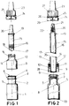
- Figure 1 is an exploded view of all of the elements that comprise the container object of the invention.
- Figure 2 is a view equivalent to the previous one in which a longitudinal section of all the elements except the cap has been made.
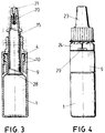
- Figure 3 is a view according to a longitudinal section of the container of the invention wherein the elements are assembled, with the exception of the cap that has been represented by a dash line for the purpose of clarifying the previous arrangement prior to use thereof.
- Figure 4 is a view equivalent to the above figure without sectioning.
- Figure 5 is a section view similar to that of figure 3, but in its arrangement for use, this after the seal has been removed and the the bottom of the top container has been broken by screwing of the cap, which is not shown in this figure.
- Figure 6 is a raised view that is not sectioned of the previous figure including the cap.
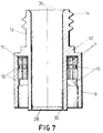
- Figure 7 is a sectioned view of the top container that coprises one of the elements of the container of the invention.
- Figure 8 is a view according to a longitudinal section of the cap and a partial sectioned view of the tubular sleeve, for the purpose of clarifying the arrangement of the cap with regard to the same.
- Figure 9 shows a plan view of the safety seal after having been separated from the cap, for the purpose of clearly showing the arrangement of the flexible wings.
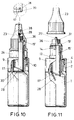
- Figure 10 is a partially sectioned view with the container totally assembled, of a possible embodiment, which includes in the wing that finishes the tubular sleeve, a hollow cylindrical extension placed outside and coaxially constituting the means that allows the coupling of the container to different medical tools.
- a hollow cylindrical extension placed outside and coaxially constituting the means that allows the coupling of the container to different medical tools.
- the way of sealing the end of the truncated-cone-shaped elements with the cap has been varied.
- Figure 11 shows a partially sectioned view of the embodiment of the above figure, but with the tearable bottom broken and the cap removed.
- the invention is comprised from a bottom container (1) in which one of the products to be mixed is inserted and that has a neck (2) which includes both ring-shaped edges (3) and (4).
- the top edge (4) is provided in the mouth of the neck (2) and just like the edge (3) it has a bevel that establishes a conicity that facilitates the automatic assembly of the top container.
- edges (3) and (4) carry out the self-centering and guiding of the top container in the assembly process.
- Edge (3) as well as edge (4) have a stria (6).
- Container (1) is provided whith a shoulder (5) whose function will be described hereinafter.
- the inside surface of the container (1), in the area of connection with the neck (2), is defined by a curved surface (8) that facilitates the outflow of the entire contents of the bottom container.
- Another characteristic of the bottom container is defined in that inside it and in the area of the neck there is a plurality of rings (7) that increase the airtightness with regard to the top container.
- the bottom container has in its base and on its edge a flat projection (33) that improves the stability of the base of said container, and therefore the stability of the entire container.
- the top container is comprised of a flap (9) that half surrounds the neck (2) and which includes on its inside surface two ring-shaped ribs (10) that are conmplemented with the ring-shaped edges (3) and (4) of the bottom container (1).
- the stria of the flap (9) as well as that of the edges (3) and (4) have a triangular section and the number of striae in either of them does not have to coincide.
- the top container has a top extension defined by a neck (13) in which there are helicoidal threads (14) that allow the cap (23) to be screwed on or screwed off, just as it will be described hereinafter.
- the top container has a bottom (28) that is tearable, for which purpose it has a perforated line (30).
- This structure allows another second product that must be mixed with the product in the bottom container (1) to be placed in the top container.
- the top container is placed over the bottom one, inserting in the neck (2) pressing on the sealing rings (7) to then locate the edge (4) in the top part of the flap (9), the edges (3) and (4) remaining retained by the action of the ring-shaped ribs.
- the stria (6) of the bottom container and the stria (11) of the top container are complemented in such a way that total axial locking of the top container and the bottom container is achieved, thus preventing that one can turn with regard to the other.
- the shoulder (5) of the bottom container Upon assembling the top container on the bottom container, the shoulder (5) of the bottom container carries out the functions of self-centering and the flap (9) can stop against it.
- a tubular sleeve (15) that is provided close to its bottom edge with a plurality of sealing rings (16) that ensure the sweeping of the powder of the product contained in the top container and at the same time they improve and guarantee the airtightness between both elements, is assembled.
- the bottom edge of the tubular sleeve (15) is defined by a helicoidal edge (17) with a bevel edge, with the exception of a small horizontal section (18) whose function will be explained hereinafter.
- the tubular sleeve (15) is finished at the top by a wing (19) from which it continues according to a truncated-cone-shaped portion (20) that comprises the medicine dropper itself, wherein inside there is a channel (22) that opens up into a slightly reversed truncated-cone-shaped hole (21), that constitutes the outlet of the drop to be applied.
- the tubular sleeve (15) has a diameter slightly smaller than in the section beween the bottom edge thereof and the first sealing ring (16), which facilitates the insertion of the tubular sleeve over the top container, achieving that the insertion stress is small and on the contrary that the removal stress is very great, which is reinforced by the convex shape that said rings (16) have.
- the insertion of the tubular sleeve in the top container is facilitated by the inclusion of a curved bevel (35) in the inner contour of the mouth of the top container.
- a ring-shaped base (34) that comprises the support means of the wing (19), just as it will be described hereinafter.
- the edge of the cap has a plurality of teeth (25) that have a widening in the bottom part thereof sideways to which the safety seal (24) is connected by a point.
- the safety seal (24) On its part the safety seal (24) is provided with a plurality of flelxible wings (26) that remain in an oblique position, and which extend beyond the top edge of the safety seal (24), in such a way that they contact with the bottom edge of the cap (25).
- the safety seal is provided with an axial wing (29) that is arranged on its surface of a furrow or stria to improve grasping by the user and whose end hs a connecting point (31), that has to be broken to remove the seal, in such a way that it comprises a safety pre-seal that also prevents snagging in the assembly machine.
- the tubular sleeve (15) facilitates the assembly of the cap (23) screwing it on the thread (14) of the top container, a circumstance that obliges the flexible wings (26) to bend upon the sawteeth (12) located in the top container, which prevents the deformation of the safety seal in the sealing, preventing locking from taking place, in such a way that it ensures the perfect sealing of the container. Screwing of the cap (23) is done until the bottom edge of the safety seal (24) rests on the flap (9), a circumstance in which the flexible wings (26) act as stopping columns, upon contacting with the edge of the cap, helping the safety seal to achieve this effect, thus increasing the stopping stress.
- the ring-shaped base (34) rests on the wing (19) of the tubular sleeve (15), pushing the tubular sleeve until it stops as cited above. Or previously the wing (19) has been located in the required position.
- the hollow cylinder (32) is inserted in the slightly truncated-cone-shaped hole (21) of the medicine dropper (20), in such a way that in the processing of screwing the hollow cylinder absorbs the radial deformation, permitting the effect of rotating and pushing the tubular sleeve without there being any problem of it being locked in the center thereof.
- the point (31) is broken by pulling on the wing (29), a circumstance that allows breakage of the connection points (35) and the points that connect the safety seal with the teeth (25), doing this breaking in a simple manner.
- the outside geometric shape of the cap (23) in the gripping area is cylindrical to prevent sliding and/or the coming loose of the cap upon screwing with the automatic screwer, besides this area has a narrow and depp striae with different curvature to improve the user's comfort and quality of the product.
- the container of the invention contemplates, consists of varying the wing (19) of the tubular sleeve (15) to obtain a wing (19') in which the inclusion of a hollow cylinder (36) that remains placed coaxially to the truncated-cone-shaped body (20) by means of which dosing takes place, is made possible.
- the hollow cylinder (36) has on its inside surface a helicoidal thread (37) in such a way that this unit allows coupling of the container to the different medical tools that are provided with a cylindrical connector that includes outside a helicoidal thread ("LUER LOK" connection) that is complemented with the helicoidal thread (37) of the hollow cylinder (36), which allows screwing on and coupling between both elements.
- a helicoidal thread (“LUER LOK" connection) that is complemented with the helicoidal thread (37) of the hollow cylinder (36), which allows screwing on and coupling between both elements.
- the truncated-cone shaped body (20) is of the conventional type, such as the one referred to as (20'), which does not include the slightly reversed truncated-cone-shaped widening (21), circumstance which makes it necessary to modify the sealing of the cap, for which purpose instead of using a hollow cylinder (32) in the cap, in the center there is a cylindrical projection (38) that is finished at the bottom with a ring-shaped edge (39), in such a way that upon screwing the cap (23) the mouth of the truncated-cone-shaped body (20') is located inside the ring-shaped edge, achieving the sealing and thus preventing the mouth of the hole of the medicine dropper from undergoing any damage or deformation.
- the bottom container is filled with the corresponding product (normally a liquid). Then it is closed with the top container and the unit is weighed, in such a way that since the weight of both containers is known one determines if the filling has b een done correctly or not. Then the top container is filled (normally with a small amount of powder) and the unit is weighed again, knowing if the filling has been correct or not. Then the tubular sleeve is assembled on the top container and the cap with the seal is screwed on, the container remaining capped and sealed.
- the second weighing can be done in any step of the assembly process after having filled the top container, since the weight of each one of the elements that comprise the container is known.
Abstract

Description
- The invention that we are now dealing with refers to a pharmaceutical container with two separate substances, and a mixing device and dosed application of the type that permit the mixing of two different substances, for which purpose it has a bottom container to house one of the products or substances, and a top container to contain the second product, the top container being retained over the bottom one, for which purpose the latter is provided in its mouth with an edge that is retained by means of a ring-shaped rib placed on the inside surface of the flap provided in the top container, which houses inside it, with the possibility of movement, a tubular sleeve whose top edge is finished with a wing after which there is a truncated-cone-shaped portion that is a medicine dropper, that is sealed by a safety seal cap that screws on the top container until the seal stops against the flap, in such a way that when the safety seal is broken, the cap continues to screw on in whose downward movement the tubular sleeve is pushed, this partially breaking the bottom of the top container, for which purpose said bottom is provided with a perforated line upon which the bottom edge of the tubular sleeve presses; the object of the invention being to achieve coupling between the bottom and top container by means of perfectly airtight sealing and without the possibility of one of the containers being able to turn over the other, obtaining greater damage-proofness of the container.
- Another object of the invention consists of providing to the tubular sleeve some means that provide for gentler cutting, facilitating the handling by the user at the same time that it prevents the effect of compacting of the powder when the product is of a powder type and the effect of the ejecting piston of the product contained in the top container is a liquid.
- Another object of the invention is to provide the coupling of this type of container in medicine droppers or correctors used in medicine to apply a product directly in the patient's vein, or in any other medical tool that has this type of connection, such as for example in eye surgery that requires the use of intra-ocular irrigations, application in sterile solutions, etc. In other words, the application permits coupling and application of the container in different medical tools.
- Besides, the invention has the object of facilitating automatic assembly of the different elements that comprise the container.
- On the other hand, the invention improves the unit defined by the cap and the safety seal, obtaining a more effective and ergnomic coupling with the top container.
- It should be indicated that the described container, allows during the assembly process that two weighings can be done, which since the weight of each one of the two elements that comprise the container is known, it is possible to determine if the filling of the bottom and top containers has been done correctly.
- The prior art closest to the invention is Spanish patent of invention no. P-9300651 of the same owner, which consists of a container of the type described above, which has the inconvenience that the bottom container can turn with regard to the top one and vice-versa, which determines an airtightness and damage-proofness that can be improved.
- Another problem that the cited patent of invention has consists of that inside the bottom container there is a connection area of the neck with the container that includes a projection that upon dosing can prevent the entire content of the bottom container from coming out.
- Besides, the tubular sleeve of said patent of invention is characterized in that the cutting area is defined by a longitudinal appendix, the remaining perimeter being flat, which can cause fastening and the cutting is not done suitably.
- Another feature of the patent of invention consists of the outlet hole of the medine dropper provided in the tubular sleeve, having a diameter, that though it is not described, is sealed by a needle that is included in the cap. This needle has to be thin, and has to be able to move rotating at the same time that pressure is exerted on the walls of the hole, which can cause it to break and to remain trapped in the hole sealing it and preventing it from operating correctly.
- Another characteristic of the indicated invention, consists of the top container having some sawteeth that are complemented with some solid sawteeth of the cap, with the same structure and in the same number as the previous ones, which represents the inconvenience that upon placing the cap on the top container, there may be deformations in the sealing ring, it being necessary to have a significant sealing stress which in some cases could cause the locking of the teeth of the cap in those of the seal, or the breaking of the seal when screwing on or screwing off takes place, thus resulting in inadequate sealing or screwing or or screwing off.
- Another feature of the cited invention, consists of that in the movement of the tubular shirt,in order to effect the cutting of the bottom of the top container, it is done by the pushing of the cap on the top part of the eye dropper that can cause the locking between both pieces, and breaking by twisting the above cited needle, which prevents the correct use thereof.
- Besides, the container of the cited patent, has the inconvenience that it cannot be coupled directly to any medical tool of those that are provided with a "LUER LOK" type connection, which consists of a cylindrical projection that has an outside thread from which the cited coupling is made possible.
- In order to solve the above cited inconveniences, the invention is characterized in that the inside surface of the flap of the top container has at least two ring-shaped ribs and a radial stria that is complemened with both ring-shaped edges located in the bottom container, that are likewise provided with a stria. This structure determines that upon coupling both containers, an airtight coupling is achieved at the same time that the possibility of one of the containers being able to rotate with regard to the other being prevented, which establishes obtainment of greater damage-proofness in view of possible mishandling.
- The ring-shaped edges of the bottom container are slightly conical to facilitate the entry of the top container and impeding removal thereof in the event of mishandling.
- Besides, said ring-shaped edges carry out the self-centering and guiding in the assembly process of the top container on the bottom container.
- The stria has a triangular section and the number striae of the top container does not have to coincide with that of the bottom container.
- The bottom container is provided with a perimetric shoulder placed in the top part thereof that can act as the stop of the top container and define a self-centering means of the latter in the assembly process.
- The base of the bottom container has a flat perimetric area that makes the container more stable.
- The inside surface of the neck of the bottom container includes a plurality of sealing rings that achieve greater airtightness in the coupling of the bottom container on the top one.
- The inside surface of the bottom container, in the connection area with the neck, is curved which makes it easier for all the product to come out.
- The bottom edge of the tubular sleeve is helicoidal with a bevel-edge, except a small horizontal section that constitutes the non-cutting area from which the partial cutting of the bottom of the top container is provided, in such a way that a gentler cutting is achieved, preventing the forming of particles at the same times that handling by the user is easier. Besides this structure of the tubular sleeve prevents the compacting effect of the powder and the effect of the ejecting piston, if the product contained in the top container is a liquid.
- The outside surface of the tubular sleeve includes a plurality of rings that ensures the sweeping of the powder that comprises the product contained in the toip cotainer and in turn they improve the airtightness and damage-proofness between both elements.
- Below the last ring provided for in the tubular sleeve, this has a diameter slightly smaller than the rest of the body, in such a way that thanks to this characteristic and to that of the rings, the stress of inserting the tubular sleeve in the top container is very small and on the contrary that of the removal is very great, preventing mishandling and that the tightening of the bottom container for dosing causes the tubular sleeve to come loose.
- Besides, the small reduction of the diameter facilitates unmolding of the tubular sleeve that is done in the manufacturing process.
- The top container is provided in the inner contour of its mouth a curved bevel that facilitates the entry of the tubular sleeve. This characteristic together with that of the smaller diameter of the bottom part of the tubular sleeve, determine greater quality of the unit, since it is not necessary to confront in an entirely exact manner the two parts for the assembly thereof, thus preventing that an alignment that is not exact from causing deformation of one of the containers, upon the tolerance being greater to insert the end of the tubular sleeve in the top container.
- The outlet hole of the truncated-cone-shaped portion that comprises the medicine dropper has a widening slightly reversed truncated-cone-shaped wherein the hollow cylindrical center pin provided for in the cap is inserted, that provides the sealing all along with widening, with the advantage that the hollow cylinder can bend in the operation of screwing on and screwing off the cap, whereby the rubbing against the inside walls of the slightly truncated-cone-shaped hole is less, achieving that the hollow cylinder neither breaks not becomes locked in said hole.
- The characteristic that the hole is slightly reversed truncated-cone shaped facilitates the control of the volume of the drop.
- The teeth the comprise the sealing means that are located in the top container are placed in a connection area of the flap, instead of being high up with regard to this point, in such a way that the maximum path and the appearance is improved avoiding dirty areas at the same time that it closes more easily.
- Besides, the safety seal of the cap has a plurality of oblique flexible wings whose number does not have to coincide with that of the teeth in the seal of the top container in such a way that said wings can bend thus the seal is not deformed when the sealing takes place, preventing the fact that a stress must be exerted on the sealing that in some cases can cause locking between the seal and the cap, in such a way that it prevents unsuitable sealing or inadequate screwing on or off.
- The connection of the cap to the safety seal is done by means of some teeth provided for in the bottom edge of the cap, that widen in the bottom part thereof and are connected to the seal by means of a side pin, in such a way that upon screwing on or off the cap together with the safety seal in order to assemble the container, the teeth stop against the projection in which there are the teeth of the top container.
- The flexible wings of the safety seal extend beyond the top edge of the latter, in such a way that they rest on the edge of the cap and are preferably located after the teeth of the bottom edge of the cap, acting as nonrotating points and stopping columns, increasing the stopping stress and allowing the bending of the connecting points of the seal to ensure correct screwing on and screwing off.
- The gripping means to effect the breaking of the seal is defined buy an axial wing that close to its free end has a point of connection to the seal in such a way that it determines a pre-seal that increases safety and prevents snagging of the handling machinery in the assembly process.
- The gripping means to effect the breaking of the seal can be determined by a radial wing.
- The cap has a ring-shaped support provided on the inside with the contact that finishes the tubular sleeve determining the pushing means of the tubular sleeve after breaking the seal and screwing on/off the cap, preventing the stop from taking place only on the tip of the medicine dropper and on the hollow cylinder, which prevents wear and malfunctioning of the unit.
- The outside surface of the cap where it is gripped by the user has a slight curve and narrower stria that facilitates the ergonomy of the same.
- According to a variant of the invention, the wing that finishes the tubular sleeve has a hollow cylindrical extension placed outside and coaxially to the truncated-cone shaped portion, in whose inside walls there is a helicoidal thread that determines a thread for coupling to the medicine dropper or another tool of those conventionally used in medicine.
- In the event that the outlet hole of the truncated-cone-shaped portion that comprises the medicine dropper does not have a slighly truncated-cone-shaped widening, as in the patent of invention cited in the prior art, then instead of using a hollow center pin provided in the top part of the cap, there is a cylindrical extension that finishes at the bottom according to a ring-shaped edge that upon screwing the cap on the container, the mouth of the hole of the truncated-cone-shaped body is located inside the ring-shaped edge, which upon sealing the cap, remaining airtight the inside of the container with the product to be applied.
- Besides, in the base of the cylindrical extension of the cap and bordering with the ring-shaped edge, a ring-shaped channel in which the edge of the truncated-cone-shaped body fits may be included, ensuring the airtight sealing.
- Besides, it should be indicated that the described container, allows assembly thereof to be done by filling first of all the bottom container and closing it with the top one in order to subsequently weight the same, in such a way it can be determined if the filling has been done correctly. Afterwards the other elements in the top container is added and it tends to be a small amount of powder, and the unit is weighed again, which allows one to know whether or not the filling has been correct. Then, the tubular sleeve is assembled and the cap is screwed on with the seal. Obviously, to know if the filling of the top container has been correct, the second weighing can be done at any time during the assembly process after having deposited the element of the top container, since the different weights that each one of the parts that make up the container are known a priori, but it is not advisable as it may impede discarding thereof.
- Hereinafter to provide a better understanding of this specification and forming an integral part of the same, a series of figures in which the object of the invention has been represented in an illustrative and non-restrictive manner are attached hereto.
- Figure 1 is an exploded view of all of the elements that comprise the container object of the invention.
- Figure 2 is a view equivalent to the previous one in which a longitudinal section of all the elements except the cap has been made.
- Figure 3 is a view according to a longitudinal section of the container of the invention wherein the elements are assembled, with the exception of the cap that has been represented by a dash line for the purpose of clarifying the previous arrangement prior to use thereof.
- Figure 4 is a view equivalent to the above figure without sectioning.
- Figure 5 is a section view similar to that of figure 3, but in its arrangement for use, this after the seal has been removed and the the bottom of the top container has been broken by screwing of the cap, which is not shown in this figure.
- Figure 6 is a raised view that is not sectioned of the previous figure including the cap.
- Figure 7 is a sectioned view of the top container that coprises one of the elements of the container of the invention.
- Figure 8 is a view according to a longitudinal section of the cap and a partial sectioned view of the tubular sleeve, for the purpose of clarifying the arrangement of the cap with regard to the same.
- Figure 9 shows a plan view of the safety seal after having been separated from the cap, for the purpose of clearly showing the arrangement of the flexible wings.
- Figure 10 is a partially sectioned view with the container totally assembled, of a possible embodiment, which includes in the wing that finishes the tubular sleeve, a hollow cylindrical extension placed outside and coaxially constituting the means that allows the coupling of the container to different medical tools. In this embodiment, the way of sealing the end of the truncated-cone-shaped elements with the cap has been varied.
- Figure 11 shows a partially sectioned view of the embodiment of the above figure, but with the tearable bottom broken and the cap removed.
- Hereinafter a description is made of the invention referring to the figures commented on in the previous section.
- The invention is comprised from a bottom container (1) in which one of the products to be mixed is inserted and that has a neck (2) which includes both ring-shaped edges (3) and (4).
- The top edge (4) is provided in the mouth of the neck (2) and just like the edge (3) it has a bevel that establishes a conicity that facilitates the automatic assembly of the top container.
- This conicity facilitates the entry of the top container and on the contrary impedes its removal in the event that the user mishandles it upon trying to disassemble them.
- Besides, said edges (3) and (4) carry out the self-centering and guiding of the top container in the assembly process.
- Edge (3) as well as edge (4) have a stria (6).
- Container (1) is provided whith a shoulder (5) whose function will be described hereinafter.
- The inside surface of the container (1), in the area of connection with the neck (2), is defined by a curved surface (8) that facilitates the outflow of the entire contents of the bottom container.
- Another characteristic of the bottom container is defined in that inside it and in the area of the neck there is a plurality of rings (7) that increase the airtightness with regard to the top container.
- Bessides, the bottom container has in its base and on its edge a flat projection (33) that improves the stability of the base of said container, and therefore the stability of the entire container.
- The top container is comprised of a flap (9) that half surrounds the neck (2) and which includes on its inside surface two ring-shaped ribs (10) that are conmplemented with the ring-shaped edges (3) and (4) of the bottom container (1).
- From the bottom ring-shaped rib (10) and along the inside surface of the flap, there is a stria that runs vertically along the wall, and that extends at the top horizontal wall (this circumstance is not visible in the figures).
- The stria of the flap (9) as well as that of the edges (3) and (4) have a triangular section and the number of striae in either of them does not have to coincide.
- The top container has a top extension defined by a neck (13) in which there are helicoidal threads (14) that allow the cap (23) to be screwed on or screwed off, just as it will be described hereinafter.
- In the connection area of the flap (9) to the neck (13) there are some teeth (12), preferably sawteeth, that comprise the fastening means of the safety seal (24) of the cap (23), just as it will be described hereinafter.
- The top container has a bottom (28) that is tearable, for which purpose it has a perforated line (30).
- This structure allows another second product that must be mixed with the product in the bottom container (1) to be placed in the top container.
- By means of the described structures of the bottom container and of the top container, it is easily understood that the top container is placed over the bottom one, inserting in the neck (2) pressing on the sealing rings (7) to then locate the edge (4) in the top part of the flap (9), the edges (3) and (4) remaining retained by the action of the ring-shaped ribs. In this arrangement, the stria (6) of the bottom container and the stria (11) of the top container are complemented in such a way that total axial locking of the top container and the bottom container is achieved, thus preventing that one can turn with regard to the other.
- Upon assembling the top container on the bottom container, the shoulder (5) of the bottom container carries out the functions of self-centering and the flap (9) can stop against it.
- Through the neck (13) of the top container a tubular sleeve (15) that is provided close to its bottom edge with a plurality of sealing rings (16) that ensure the sweeping of the powder of the product contained in the top container and at the same time they improve and guarantee the airtightness between both elements, is assembled.
- The bottom edge of the tubular sleeve (15) is defined by a helicoidal edge (17) with a bevel edge, with the exception of a small horizontal section (18) whose function will be explained hereinafter.
- The tubular sleeve (15) is finished at the top by a wing (19) from which it continues according to a truncated-cone-shaped portion (20) that comprises the medicine dropper itself, wherein inside there is a channel (22) that opens up into a slightly reversed truncated-cone-shaped hole (21), that constitutes the outlet of the drop to be applied.
- After assembling the tubular sleeve, its wing (19) remains separated a certain distance from the mouth of the top container, which facilitates that along with the truncated-cone-shaped portion (20) a self-centering means is provided upon assemblying the cap, ensuring a correct screwing on and screwing off.
- The tubular sleeve (15) has a diameter slightly smaller than in the section beween the bottom edge thereof and the first sealing ring (16), which facilitates the insertion of the tubular sleeve over the top container, achieving that the insertion stress is small and on the contrary that the removal stress is very great, which is reinforced by the convex shape that said rings (16) have.
- Besides, the insertion of the tubular sleeve in the top container is facilitated by the inclusion of a curved bevel (35) in the inner contour of the mouth of the top container.
- In the inside of the cap there is a ring-shaped base (34) that comprises the support means of the wing (19), just as it will be described hereinafter.
- Besides, the edge of the cap has a plurality of teeth (25) that have a widening in the bottom part thereof sideways to which the safety seal (24) is connected by a point.
- On its part the safety seal (24) is provided with a plurality of flelxible wings (26) that remain in an oblique position, and which extend beyond the top edge of the safety seal (24), in such a way that they contact with the bottom edge of the cap (25).
- Besides, the safety seal is provided with an axial wing (29) that is arranged on its surface of a furrow or stria to improve grasping by the user and whose end hs a connecting point (31), that has to be broken to remove the seal, in such a way that it comprises a safety pre-seal that also prevents snagging in the assembly machine.
- It should be pointed out that in the inside top part of the cap there is a hollow cylinder (32) that comprises the sealing means of the hole (21) of the medicine dropper (20), just as it is described hereinafter.
- Once the tubular sleeve (15) has been assembled on the top container, just it was already described, it facilitates the assembly of the cap (23) screwing it on the thread (14) of the top container, a circumstance that obliges the flexible wings (26) to bend upon the sawteeth (12) located in the top container, which prevents the deformation of the safety seal in the sealing, preventing locking from taking place, in such a way that it ensures the perfect sealing of the container. Screwing of the cap (23) is done until the bottom edge of the safety seal (24) rests on the flap (9), a circumstance in which the flexible wings (26) act as stopping columns, upon contacting with the edge of the cap, helping the safety seal to achieve this effect, thus increasing the stopping stress.
- In the process of screwing the cap, the ring-shaped base (34) rests on the wing (19) of the tubular sleeve (15), pushing the tubular sleeve until it stops as cited above. Or previously the wing (19) has been located in the required position.
- Besides, in this situation, the hollow cylinder (32) is inserted in the slightly truncated-cone-shaped hole (21) of the medicine dropper (20), in such a way that in the processing of screwing the hollow cylinder absorbs the radial deformation, permitting the effect of rotating and pushing the tubular sleeve without there being any problem of it being locked in the center thereof.
- Once the different elements that comprise the container of the invention have been assembled and sealed, in order to begin to use the container, the point (31) is broken by pulling on the wing (29), a circumstance that allows breakage of the connection points (35) and the points that connect the safety seal with the teeth (25), doing this breaking in a simple manner.
- In this circumstance, one can continue to screw the cap (23) on the thread (14) of the top container, a circumstance that determines that the ring-shaped base (34) presses on the wing (19) forcing the tubular sleeve (15) to move axially. In the movement thereof, its helicoidal edge (17) presses on the tearable bottom that defines a gentle cutting that prevents the forming of particles and facilitates handling by the user, said tearing being done all along the helicoidal surface, with the exception of the horizontal point (18), commented on above, whereby the tearable bottom (28) does not come loose and it remains connected to the top container, just as it is shown in figure 5.
- The operations of screwing on and screwing off the cap are made easier by the arrangment of the striae (6) and (11) that prevent the top and bottom containers from turning with regard to each other, as it has b een commented on above.
- It is important to point out that the number of flexible wings (26) does not have to coincide in number or position with the sawteeth (12) provided for in the top container, which prevents locking.
- It is obvious that said flexible wings (26), though they have been described with an oblique shape, they may be likewise radial.
- The outside geometric shape of the cap (23) in the gripping area is cylindrical to prevent sliding and/or the coming loose of the cap upon screwing with the automatic screwer, besides this area has a narrow and depp striae with different curvature to improve the user's comfort and quality of the product.
- Another possibility that the container of the invention contemplates, consists of varying the wing (19) of the tubular sleeve (15) to obtain a wing (19') in which the inclusion of a hollow cylinder (36) that remains placed coaxially to the truncated-cone-shaped body (20) by means of which dosing takes place, is made possible.
- The hollow cylinder (36) has on its inside surface a helicoidal thread (37) in such a way that this unit allows coupling of the container to the different medical tools that are provided with a cylindrical connector that includes outside a helicoidal thread ("LUER LOK" connection) that is complemented with the helicoidal thread (37) of the hollow cylinder (36), which allows screwing on and coupling between both elements.
- There is the possiblity that the truncated-cone shaped body (20) is of the conventional type, such as the one referred to as (20'), which does not include the slightly reversed truncated-cone-shaped widening (21), circumstance which makes it necessary to modify the sealing of the cap, for which purpose instead of using a hollow cylinder (32) in the cap, in the center there is a cylindrical projection (38) that is finished at the bottom with a ring-shaped edge (39), in such a way that upon screwing the cap (23) the mouth of the truncated-cone-shaped body (20') is located inside the ring-shaped edge, achieving the sealing and thus preventing the mouth of the hole of the medicine dropper from undergoing any damage or deformation.
- There are truncated-cone-shaped portions (20') in whose mouth there is a perimetric edge, for which purpose the base of the cylindric body (38) and then the ring-shaped edge (39) include a ring-shaped channel (40) wherein the said perimetric edge of the truncated-cone-shaped body (20') is located, achieving the perfect sealing of the container.
- Therefore, by means of the structure described, a container with a greater airtightness and damage-proofness against undesired actions is achieved, at the same time that it has a superior ergonomy and its assembly is made easier as done in the process that is described hereinafter.
- First of all, the bottom container is filled with the corresponding product (normally a liquid). Then it is closed with the top container and the unit is weighed, in such a way that since the weight of both containers is known one determines if the filling has b een done correctly or not. Then the top container is filled (normally with a small amount of powder) and the unit is weighed again, knowing if the filling has been correct or not. Then the tubular sleeve is assembled on the top container and the cap with the seal is screwed on, the container remaining capped and sealed.
- It is obvious that the second weighing can be done in any step of the assembly process after having filled the top container, since the weight of each one of the elements that comprise the container is known.
Claims (28)
- Pharmaceutical container with two separate substances and a mixing device and dosed application, of the type that have a bottom container (1) to house a first product and a top container to container a second product, retaining the top container over the bottom one, for which purpose the latter is provided on its mouth with a endge(4) that is retained by means of a ring-shaped rib placed on the inside surface of a flap (9) provided on the top container; it being provided for that inside the top container there is, with the possibility of movement, a tubular sleeve (15) whose top edge is finished with a wing (19) after which there is a truncated-cone-shaped portion (20) as a medicine dropper, that is sealed by a cap (23) with a safety seal (24) that is screwed on the top container in such a way that upon acting on the gripping means of the safety seal (24) breaking it, one can continue screwing on the cap (23) in whose downward movement the tubular sleeve (15) is pushed and the sleeve partially breaks the bottom (28) of the top container, for which purpose said bottom is provided with a perforated line (30) on which presses the bottom edge (17) of the tubular sleeve which is beveled; the locking of the safety seal (24) taking place in the sealing, upon some sawteeth (12) placed on the neck (13) of the top container; is characterized in that the inside surface of the flap (9) of the top container has two ring-shaped ribs (10) and with a stria (11) that is complemented with both ring-shjaped edges (3) and 4) located in the bottom container (1), which likewise have a stria (6); all in order so that upon both containers coupling there is an airtight connection and preventing incorrect use without the possibility of one of the containers turning on the other achieving easier use.
- Pharmaceutical container with two separate substances and a mixing device and dosed application, according to claim 1, characterized in that the top container has a perimetric shoulder (5) that comprises a self-centering means and a safety stop of the edge of the flap of the top container in the assembly process.
- Pharmaceutical container with two separate substances and a mixing device and dosed application, according to claim 1, characterized in that the ring-shaped edges (3) and (4) of the bottom container have a bevel that facilitates automatic assembly of the containers.
- Pharmaceutical container with two separate substances, and a mixing device and dosed application, according to claim 1, characterized in that the ring-shaped edges (3) and (4) of the bottom container constitute a self-centering means upon assembling the top container.
- Pharmaceutical container with two separate substances and a mixing device and dosed application, according to claim 1, characterized in that the base of the bottom container (1) has a flat perimetric area (33) acheiving greater stability.
- Pharmaceutical container with separate substances, and a mixing device and dosed application, according to claim 1, characterized in that the inside surface of the neck of the bottom container (1) includes a plurality of sealing rings (7).
- Pharmaceutical container with two separate substances, and a mixing device and dosed application, according to claim 1, characterized in that the bottom container (1) in the connection area with the neck, has a curvature (8) that facilitates the outflow of all the product.
- Pharmaceutical container with two separate substances, and a mixing device and dosed application, according to claim 1, characterized in that the bottom edge (17) of the tubular sleeve (15) is helicoidal with a bevel edge, with the exception of a small horizontal section (18) that constitutes the non-cutting area that provides the partial cutting of the tearable bottom (28) of the top container.
- Pharmaceutical container with two separate substances, and a mixing device and dosed application, according to claim 1, characterized in that the outside surface of the tubular sleeve (15) includes a plurality of sealing rings (16) that facilitate the swepping of the product contained in the top container and impedes removal thereof from the top container.
- Pharmaceutical container with two separate substances, and a mixing device and dosed application, according to claims 1 and 9, characterized in that the sectin below the last sealing ring (16) of the tubular sleeve (15) has a diameter slightly smaller than the rest of the body, facilitating its assembly on the top container.
- Pharmaceutical container with two separate substances, and a mixing device and dosed application, according to claim 1, characterized in that the inner contour of the mouth of the top container has a curved bevel (36) that facilitates insertion of the tubular sleeve (15).
- Pharmaceutical container with two spearate substances, and a mixing device and dosed application, according to claim 1, characterized in that the outlet hole of the medicine dropper (20) has a slightly reversed truncated-cone-shaped widening (21) in which a hollow cylindrical center pin (32) provided for in the cap, is located, that provides sealing and facilitates the turning of the cap (23.)
- Pharmaceutical container with two separate substances, and a mixing device and dosed application, according to claim 1, characterized in that the teeth of the seal (12) located in the neck (13) of the top container are placed in the area of connection with the flap (9).
- Pharmaceutical container of two separate substances, and a mixing device and dosed application, according to claims 1 and 13, characterized in that the safety seal of the cap has a series of oblique flexible wings whose number does not have to cincide with that of the teeth (12) of the seal of the top container; all in order to prevent the safety seal (24) of the cap from being deformed when sealing takes place.
- Pharmaceutical container with two separate substances, according to claim 14, characterized in that the flexible wings may be radial.
- Pharmaceutical container with two separate substances and a mixing device and dosed application, according to claims 1 and 13, characterized in that the connection of the cap (23) to the safety seal (24) is done by means of some teeth (259 provided for in the bottom edge of the cap, that widen in the bottom part thereof and connect to the safety seal by means of a side point, so that upon removing the seal the teeth may be the stopping means upon the projection in which there are teeth (12) of the seal of the top container.
- Pharmaceutical container with two separate substances, and a mixing device and dosed application, according to claims 14, 15 and 16, characterized int aht the flexible wings (26) of the safety seal (24) project beyond the top edge of the latter, in such a way that they rest on the edge of the cap and they are preferably located after the teeth (25) of the bottom edge of the cap, acting as non-rotation points and stopping columns increasing the stopping stress upon effecting the sealing; the connection points being able to bend to absorb the manufacturing and assembly tolerances.
- Pharmaceutical container with two separate substances, and a mixing device and dosed application, according to claim 1, characterized in that the gripping means to effect the breaking opf the safety seal (24) is defined by an axial wing (29) which close to its free end has a point for connection (31) to the seal, defining a pre-seal that increases the safety and prevents snagging in the handling and assembly machinery of the container.
- Pharmaceutical container with two separate substances and a mixing device and dosed application, accrding to claim 18, characterized in that the gripping means to effect the breaking of the safety seal (24) is defined by an axial wing.
- Pharmaceutical container with two substances, and a mixing device and dosed application, according to claims 18 and 19, characterized in that the grasping means has on its surface a furrow that facilitates gripping by the user.
- Pharmaceutical container with two separate substances and a mixing device and dosed application, according to claim 1, characterized in that the cap has a ring-shaped support (34) that contacts with the wing (19) that ends the tubular sleeve (15), detgermining the pushing means of the tubular sleeve, aftr breaking the safety seal (24) and screwing the cap (23) on the top container.
- Pharmaceutical container with two separate substances, and a mixing device and dosed application, according to claim 1, characterized in that the cap has an outside geometric shaped on its cylindric gripping point and in it there is a narrow deep striawith a different durvature, that facilitates screwing on during the assembly process.
- Pharmaceutical container with two substances and a mixing device and dosed application, according to claim 1, characterized that in the area of connection of the tubular sleeve (15) with the truncated-cone-shaped portion (20), there is a wing (19') wherein there is a hollow cylindric extension (36) provide outside and coaxialy to the truncated-cone-shaped portion (20), in whose inside walls there is a helicoidal thread (37) that defines a thread for coupling to a medicine dropper or another tool used conventionally in medicine that has a cylindrical extension in whose outside walls there is a thread in which the hollow cylinder (36) is retained.
- Pharmaceutical container with two substances and a mixing device and dosed application, according to claim 1, characterized in that the element placed on the cap (23) that seals the outlet of the truncated-cone-shaped body (20') is defined by a cylindrical body (38) that ends at the bottom with a ring-shaped edge (39), in such a way that upon closing and/or sealing, the mouth of the truncated-cone-shaped body (20') remains located in the inside of the ring-shaped edge (39).
- Pharmaceutical container with two separate substances, and a mixing device and dosed applicatin, according to claims 1 and 24, characterized in that in the ev ent that the truncated-cone-shaped body is finished at the top by a perimetric edge the base of the cylindric body (38) and after the ring-shaped edge (39), includes a ring-shaped channel (40), in such a way that upon closing and/or sealing, the perimetric edge of the truncated-cone-shaped body (20') remains located in the ring-shaped channel (40).
- Assembly process of a container of application to the container of the previous claims, characterized in that the bottom container is filled, it is closed with the top container and the unit is weighed, determining if the filling has been correct, then the top container is filled and the unit is weighed again, determining if the filling has been correct; then the tubular sleeve is assembled on the top container and the cap with the seal is screwed on.
- Assembly process of a container of the above claim, characterized in that the second weighing is done after assembling the tubular sleeve.
- Assembly process of a container, according to claim 24, characterized in that the second weighing is done after the cap is assembled.
Applications Claiming Priority (2)
| Application Number | Priority Date | Filing Date | Title |
|---|---|---|---|
| ES009502392A ES2128220B1 (en) | 1995-12-04 | 1995-12-04 | PHARMACEUTICAL CONTAINER OF TWO SEPARATE SUBSTANCES, WITH MIXING DEVICE, DOSAGE APPLICATION AND ITS ASSEMBLY PROCESS. |
| ES9502392 | 1995-12-04 |
Publications (2)
| Publication Number | Publication Date |
|---|---|
| EP0778221A1 true EP0778221A1 (en) | 1997-06-11 |
| EP0778221B1 EP0778221B1 (en) | 2000-03-22 |
Family
ID=8292388
Family Applications (1)
| Application Number | Title | Priority Date | Filing Date |
|---|---|---|---|
| EP95203629A Expired - Lifetime EP0778221B1 (en) | 1995-12-04 | 1995-12-27 | Pharmaceutical container with two seperate substances, with means for mixing and for the dosed application of the substances, and assembly process thereof |
Country Status (17)
| Country | Link |
|---|---|
| US (1) | US5782345A (en) |
| EP (1) | EP0778221B1 (en) |
| JP (1) | JP4058119B2 (en) |
| CN (1) | CN1127332C (en) |
| AT (1) | ATE190946T1 (en) |
| AU (1) | AU711119B2 (en) |
| CA (1) | CA2166224C (en) |
| DE (1) | DE69515885T2 (en) |
| DK (1) | DK0778221T3 (en) |
| ES (1) | ES2128220B1 (en) |
| FI (1) | FI112914B (en) |
| GR (1) | GR3033650T3 (en) |
| HK (1) | HK1011961A1 (en) |
| IN (1) | IN192810B (en) |
| MX (1) | MX9600026A (en) |
| PT (1) | PT778221E (en) |
| RU (1) | RU2157682C2 (en) |
Cited By (25)
| Publication number | Priority date | Publication date | Assignee | Title |
|---|---|---|---|---|
| WO2000019961A1 (en) * | 1998-10-02 | 2000-04-13 | Giuseppe Santoro | Container for two phases injectable drugs |
| WO2000023037A1 (en) * | 1998-10-17 | 2000-04-27 | Boehringer Ingelheim Pharma Kg | Two chamber cartridge for atomizers |
| WO2001046035A1 (en) * | 1999-12-20 | 2001-06-28 | Alcon Universal Ltd. | Container with two compartments and a mixing device |
| EP1122186A1 (en) * | 1999-12-20 | 2001-08-08 | Alcon Universal, Ltd. | Pharmaceutical container with two seperate, unstable substances |
| WO2003059774A2 (en) * | 2002-01-17 | 2003-07-24 | Prof. Birkmayer Gesundheitsprodukte Gmbh | Rotating closure for a container |
| WO2003059773A2 (en) * | 2002-01-17 | 2003-07-24 | Prof. Birkmayer Gesundheitsprodukte Gmbh | Closing device for a container |
| FR2867761A1 (en) * | 2004-03-19 | 2005-09-23 | Mt Packaging | RECHARCHE FOR COSMETIC PRODUCT DISTRIBUTOR |
| US7210575B2 (en) | 2002-09-26 | 2007-05-01 | Boehringer Ingelheim International Gmbh | Two-component packaging unit |
| EP2003068A1 (en) * | 2007-06-11 | 2008-12-17 | GIULIANI S.p.A. | Dispenser group of a substance soluble in water applicable to a mouth of a liquid container |
| EP2049432A1 (en) * | 2006-07-31 | 2009-04-22 | Liqui-Box Canada Inc. | A piercing fitment assembly |
| US9545487B2 (en) | 2012-04-13 | 2017-01-17 | Boehringer Ingelheim International Gmbh | Dispenser with encoding means |
| US9682202B2 (en) | 2009-05-18 | 2017-06-20 | Boehringer Ingelheim International Gmbh | Adapter, inhalation device, and atomizer |
| US9724482B2 (en) | 2009-11-25 | 2017-08-08 | Boehringer Ingelheim International Gmbh | Nebulizer |
| US9744313B2 (en) | 2013-08-09 | 2017-08-29 | Boehringer Ingelheim International Gmbh | Nebulizer |
| US9757750B2 (en) | 2011-04-01 | 2017-09-12 | Boehringer Ingelheim International Gmbh | Medicinal device with container |
| US9827384B2 (en) | 2011-05-23 | 2017-11-28 | Boehringer Ingelheim International Gmbh | Nebulizer |
| US9943654B2 (en) | 2010-06-24 | 2018-04-17 | Boehringer Ingelheim International Gmbh | Nebulizer |
| US10004857B2 (en) | 2013-08-09 | 2018-06-26 | Boehringer Ingelheim International Gmbh | Nebulizer |
| US10011906B2 (en) | 2009-03-31 | 2018-07-03 | Beohringer Ingelheim International Gmbh | Method for coating a surface of a component |
| US10016568B2 (en) | 2009-11-25 | 2018-07-10 | Boehringer Ingelheim International Gmbh | Nebulizer |
| US10099022B2 (en) | 2014-05-07 | 2018-10-16 | Boehringer Ingelheim International Gmbh | Nebulizer |
| US10124129B2 (en) | 2008-01-02 | 2018-11-13 | Boehringer Ingelheim International Gmbh | Dispensing device, storage device and method for dispensing a formulation |
| US10124125B2 (en) | 2009-11-25 | 2018-11-13 | Boehringer Ingelheim International Gmbh | Nebulizer |
| US10195374B2 (en) | 2014-05-07 | 2019-02-05 | Boehringer Ingelheim International Gmbh | Container, nebulizer and use |
| US10722666B2 (en) | 2014-05-07 | 2020-07-28 | Boehringer Ingelheim International Gmbh | Nebulizer with axially movable and lockable container and indicator |
Families Citing this family (81)
| Publication number | Priority date | Publication date | Assignee | Title |
|---|---|---|---|---|
| US9452870B1 (en) | 1987-01-20 | 2016-09-27 | Michael Anderson | Two-piece double-sealed dispensing capsule with button blast and drink through feature |
| DE19615422A1 (en) | 1996-04-19 | 1997-11-20 | Boehringer Ingelheim Kg | Two-chamber cartridge for propellant-free MDIs |
| WO1998040289A1 (en) * | 1997-03-12 | 1998-09-17 | Fredrick Michael Coory | Discharge cap with releasable tablet basket |
| US5927549A (en) * | 1998-03-20 | 1999-07-27 | Aptargroup, Inc. | Dispensing structure with frangible membrane for separating two products |
| USD421495S (en) * | 1998-03-25 | 2000-03-07 | Abbott Laboratories | Pharmaceutical container |
| DE19831235C1 (en) * | 1998-07-11 | 2000-03-16 | Fresenius Ag | Sterile connector for containers containing medical liquids |
| SE9902610D0 (en) * | 1999-07-07 | 1999-07-07 | Astra Ab | Sealing device at medical container |
| US6164495A (en) * | 1999-11-02 | 2000-12-26 | Manesis; Nick J. | Metered dispensing device |
| JP2003514722A (en) | 1999-11-17 | 2003-04-22 | マイケル クーリ フレドリック | Penetration cap for container |
| GB2366288B (en) * | 2000-08-31 | 2004-03-10 | Inge Spa | Sealing device for a container of substances to be kept separate up to their dispensing |
| FR2814155B1 (en) * | 2000-09-15 | 2003-02-21 | Oreal | CONTAINER WITH AT LEAST TWO COMPARTMENTS AND MIXER EQUIPPED WITH SUCH A CONTAINER |
| US6533113B2 (en) | 2000-12-01 | 2003-03-18 | Brett Moscovitz | System, devices and methods for storing and mixing substances |
| US6527110B2 (en) | 2000-12-01 | 2003-03-04 | Brett Moscovitz | Device for storing and dispensing a substance by mating with a container and associated methods |
| US6543612B2 (en) * | 2001-05-21 | 2003-04-08 | 3M Innovative Properties Company | Container for compositions made of two or more components |
| BR0210493A (en) * | 2001-07-03 | 2004-06-22 | Alcon Inc | Composition and method for removing human wax |
| KR200266847Y1 (en) * | 2001-12-05 | 2002-03-04 | (주)연우 | dispenser |
| US7219796B2 (en) * | 2002-05-24 | 2007-05-22 | Vision International Production, Inc. | Dispensing capsule for a liquid container |
| AU2002951977A0 (en) | 2002-10-10 | 2002-10-24 | Leo Engineering Pty Ltd | Improvements to two-part vessels |
| US6910573B2 (en) * | 2003-04-24 | 2005-06-28 | David M. Deans | Dual container bottle |
| AU2003204438B1 (en) * | 2003-05-30 | 2004-02-05 | Sailnote Pty Ltd. | Hair colourant applicator |
| RU2369545C2 (en) * | 2003-09-09 | 2009-10-10 | Арон Жозеф КЛАРКСОН | Dispensing cover |
| WO2005056402A1 (en) * | 2003-12-09 | 2005-06-23 | Martin Bochtler | System for combining liquids |
| US8215481B1 (en) | 2004-02-18 | 2012-07-10 | Knickerbocker Michael G | Container closure for retaining an additive material |
| EP2298664B1 (en) * | 2004-09-29 | 2012-03-21 | Yoshino Kogyosho Co., Ltd. | Container for mixing two liquids and the like |
| JP4684611B2 (en) * | 2004-09-30 | 2011-05-18 | 株式会社吉野工業所 | Two kinds of contents mixing container |
| JP4580726B2 (en) * | 2004-10-08 | 2010-11-17 | 日本高圧電気株式会社 | Beverage container cap structure |
| KR100634354B1 (en) * | 2004-11-23 | 2006-10-16 | 조영국 | Double cap for adding addition in use |
| KR100597217B1 (en) * | 2004-11-23 | 2006-07-06 | 조영국 | Double cap for adding addition in use |
| BRPI0518891A2 (en) * | 2004-12-10 | 2008-12-16 | Alcon Inc | topically atypical pharmaceutical composition |
| US20100236952A1 (en) * | 2004-12-24 | 2010-09-23 | Berry Plastics Corporation | Solute-dispensing closure |
| US20060006077A1 (en) * | 2004-12-24 | 2006-01-12 | Erie County Plastics Corporation | Dispensing closure with integral piercing unit |
| US7308915B2 (en) * | 2005-04-21 | 2007-12-18 | Jpro Dairy International, Inc. | Packaging system for storing and mixing separate ingredient components |
| US7607555B2 (en) * | 2006-03-01 | 2009-10-27 | Ds Smith Plastics Limited | Puncturable cap and piercer |
| US8771711B2 (en) | 2006-04-21 | 2014-07-08 | Toko Yakuhin Kogyo Kabushiki Kaisha | Sprayable gel-type skin/mucosa-adhesive preparation and administration system using the preparation |
| KR101370721B1 (en) * | 2006-04-21 | 2014-03-06 | 신코 케미칼 가부시키가이샤 | Fluid container and airless fluid dispensing system |
| US7635012B2 (en) * | 2006-06-12 | 2009-12-22 | Jpro Dairy International, Inc. | Sealed storage container with a coupling assembly |
| US7607460B2 (en) * | 2006-06-12 | 2009-10-27 | Jpro Dairy International, Inc. | Coupling assembly |
| US8727113B2 (en) * | 2006-07-12 | 2014-05-20 | Hal P. Robb | Multiple substance mixing container system |
| US7951109B2 (en) * | 2006-09-22 | 2011-05-31 | Andeboh Holdings, Flp | Liquid chamber cap with compartment for use with injectables |
| US20080245683A1 (en) * | 2007-04-04 | 2008-10-09 | Injexxion, Inc. | Container for Keeping Component Separate up to Their Use |
| US8070014B2 (en) | 2007-08-24 | 2011-12-06 | Seaquist Closures L.L.C. | Liner piercing twist closure |
| HK1117990A2 (en) * | 2007-10-25 | 2009-01-23 | Sunrider Corp | Safety sealed reservoir cap |
| WO2009096803A1 (en) * | 2008-01-29 | 2009-08-06 | Skvortsov, Igor Victorovich | 'expromt' bottle |
| US7997509B2 (en) * | 2008-04-08 | 2011-08-16 | Dana Karklins | Portion-controlled dispensing straw assembly |
| US8771615B2 (en) * | 2008-04-24 | 2014-07-08 | Toyo Seikan Kaisha, Ltd. | Compound container and pouring-out method |
| US8485378B2 (en) * | 2009-04-08 | 2013-07-16 | General Mills, Inc. | Multi-container packages for dispensing liquid and dry food |
| BRPI0820125B1 (en) * | 2008-09-10 | 2018-12-04 | Bormioli Rocco S.P.A. | safety cap with rupturable reservoir and cutter. |
| US8079483B2 (en) | 2008-09-11 | 2011-12-20 | Rexam Healthcare Packaging Inc. | Closure with stopping mechanism |
| US8123058B2 (en) | 2008-09-11 | 2012-02-28 | Rexam Healthcare Packaging Inc. | Closure with stopping mechanism |
| US8801688B2 (en) * | 2008-10-14 | 2014-08-12 | Mead Johnson Nutrition Company | Nutritive substance delivery container |
| US20100122991A1 (en) * | 2008-11-17 | 2010-05-20 | The Coca-Cola Company | Sealable cap for spout |
| US8701906B1 (en) | 2008-12-31 | 2014-04-22 | Blast Max Llc | Ingredient dispensing cap for mixing beverages with push-pull drinking spout |
| WO2010080707A1 (en) | 2009-01-09 | 2010-07-15 | Vitality Foodservice, Inc. | Coupling for pump and container |
| US8684208B2 (en) * | 2009-05-14 | 2014-04-01 | Chris Hotell | Reusable containers for storing foodstuffs or liquids |
| US20110011822A1 (en) * | 2009-07-16 | 2011-01-20 | Genmont Biotech Incorporation | Bottle cap |
| US8226126B2 (en) * | 2009-08-24 | 2012-07-24 | Jpro Dairy International, Inc. | Bottle mixing assembly |
| JP5735797B2 (en) * | 2010-12-29 | 2015-06-17 | 東洋製罐株式会社 | Double container |
| ITMI20110054U1 (en) * | 2011-02-16 | 2011-05-18 | Federico Thoman | BOTTLE WITH DISPENSER CAP |
| KR101168232B1 (en) * | 2011-03-25 | 2012-07-30 | 바디텍메드 주식회사 | Integrated sampling and dispensing device |
| US9242773B1 (en) * | 2011-05-27 | 2016-01-26 | Michael R. Anderson | Dispensing capsule with button blast and drinking feature |
| US9567142B1 (en) | 2011-05-27 | 2017-02-14 | Michael Anderson | One-piece dispensing capsule with integral plunger |
| US9242772B1 (en) * | 2011-05-27 | 2016-01-26 | Michael R. Anderson | Drink-through dispensing capsule with snap in activation chamber |
| JP2014528337A (en) | 2011-10-14 | 2014-10-27 | ノボ ノルディスク ヘルス ケア アーゲー | Pre-assembled fluid transfer device |
| JP5991101B2 (en) * | 2012-09-14 | 2016-09-14 | 東洋製罐株式会社 | Container with cap |
| US20150321782A1 (en) * | 2014-05-08 | 2015-11-12 | Houser Products, Llc | Dispensing Vessel and Method of Use |
| JP6338977B2 (en) * | 2014-08-29 | 2018-06-06 | 株式会社吉野工業所 | Two-component mixing container |
| US10065785B2 (en) * | 2015-04-21 | 2018-09-04 | Mihail Genchev | Dual compartment mixing fluid bottle |
| CN105129246A (en) * | 2015-09-06 | 2015-12-09 | 无锡贝迪生物工程有限公司 | Preparation method of compound liquid product |
| CN105125340A (en) * | 2015-09-10 | 2015-12-09 | 成都华神生物技术有限责任公司 | Medicine solution preparing device, using method thereof, medicine using device and using method thereof |
| KR20170078392A (en) * | 2015-12-29 | 2017-07-07 | 주식회사 에프에스코리아 | Cosmetic container |
| WO2017204381A1 (en) * | 2016-05-26 | 2017-11-30 | 주식회사 다린 | Cartridge pump |
| IT201600080494A1 (en) * | 2016-08-01 | 2018-02-01 | Lameplast Spa | PACKAGING FOR PRODUCTS WITH ESTEMPORANEA PREPARATION, PARTICULARLY MEDICINAL, PHARMACEUTICAL, COSMETIC OR SIMILAR |
| US10577153B2 (en) * | 2016-09-20 | 2020-03-03 | Babatope Sewande Ayeni | Disposable dual beverage holding receptacle |
| JP2020501665A (en) * | 2016-12-21 | 2020-01-23 | ベーリンガー インゲルハイム インターナショナル ゲゼルシャフト ミット ベシュレンクテル ハフツング | Nebulizer and cartridge |
| DE102017109255A1 (en) * | 2017-04-28 | 2018-10-31 | Heraeus Medical Gmbh | Bone cement application device with closure means on the discharge piston |
| US10640275B2 (en) * | 2017-06-12 | 2020-05-05 | Bio-Techne Corportion | Dual chamber storage device |
| CN111417583B (en) * | 2017-12-01 | 2022-09-20 | 欧莱雅 | Device for packaging two products separately |
| CN110239837A (en) * | 2019-07-12 | 2019-09-17 | 上海艾鲲新材料科技有限公司 | Sealing container |
| PL244752B1 (en) * | 2020-01-17 | 2024-03-04 | Gerresheimer Boleslawiec Spolka Akcyjna | Container, in particular for medication |
| JP2023535215A (en) * | 2020-07-22 | 2023-08-16 | スマート キャップ ライセンシング ピーティーワイ リミテッド | Feeding device, system and method |
| US11498729B1 (en) | 2022-03-02 | 2022-11-15 | Jennifer Dianne Hugo | Dispenser |
Citations (4)
| Publication number | Priority date | Publication date | Assignee | Title |
|---|---|---|---|---|
| US4465183A (en) * | 1982-07-19 | 1984-08-14 | Kao Soap Co., Ltd. | Two-part liquid container with breakable partition |
| EP0251193A1 (en) * | 1986-06-27 | 1988-01-07 | Bristol-Myers Squibb Company | Dual compartment container |
| EP0561322A1 (en) * | 1992-03-19 | 1993-09-22 | Lameplast S.R.L. | Dropper bottle for two products to be mixed prior to use |
| EP0577200A1 (en) * | 1992-07-02 | 1994-01-05 | Laboratorios Cusi, S.A. | Pharmaceutical product container for two separate substances, having a device for mixing and dosed dispensation |
Family Cites Families (18)
| Publication number | Priority date | Publication date | Assignee | Title |
|---|---|---|---|---|
| US2718980A (en) * | 1951-10-02 | 1955-09-27 | Robinson William H | Container seal |
| BE794915A (en) * | 1972-02-03 | 1973-08-02 | Inge Spa | CLOSING DEVICE FOR BOTTLES AND ANALOGUES, ALLOWING SEPARATE STORAGE OF INGREDIENTS TO BE MIXED AT THE TIME OF USE |
| IT1185850B (en) * | 1985-08-02 | 1987-11-18 | Zambon Spa | DROP TANK CAP FOR BOTTLES |
| JPH0212215Y2 (en) * | 1985-12-26 | 1990-04-05 | ||
| FR2600631B1 (en) * | 1986-06-26 | 1989-03-31 | Rical Sa | TAMPER ASSEMBLY AND CAPPING CAP |
| FR2603869B1 (en) * | 1986-09-12 | 1988-11-18 | Oreal | ASSEMBLY FOR SEPARATELY PACKAGING TWO PRODUCTS AND FOR DISTRIBUTING SIMULTANEOUSLY AFTER THEIR CONTACT |
| EP0338349B2 (en) * | 1988-04-18 | 1995-06-28 | Capsulit S.P.A. | Closure for monodose bottles and the like, comprising a reservoir provided with a breakable bottom |
| IT1217761B (en) * | 1988-06-01 | 1990-03-30 | Dam Technological Research Ltd | TANK CAP FOR POWDERS |
| JPH0412991Y2 (en) * | 1988-09-06 | 1992-03-27 | ||
| DE4016282A1 (en) * | 1990-05-21 | 1991-11-28 | Finke Robert Gmbh | MULTI-COMPONENT PACK |
| FR2666305B1 (en) * | 1990-09-05 | 1992-11-13 | Oreal | DEVICE FOR STORING AT LEAST TWO PRODUCTS AT LEAST TWO PRODUCTS AND FOR MAKING THEIR MIXTURE AT THE TIME OF USE. |
| JPH04106266U (en) * | 1991-02-18 | 1992-09-14 | 千寿製薬株式会社 | Container for dropping two-drug mixture |
| ES2064277B1 (en) * | 1993-03-30 | 1995-09-01 | Cusi Lab | PHARMACEUTICAL PRODUCTS CONTAINER, WITH TWO SEPARATE SUBSTANCES AND MIXING DEVICE AND DISPENSED DOSAGE. |
| IT227015Y1 (en) * | 1992-11-27 | 1997-09-09 | Ibsa Inst Biochimique Sa | DOSING DEVICE FOR MULTIDOSE EXEMPORARY SYRUPS FOR PHARMACEUTICAL USE |
| JPH071260A (en) * | 1993-06-15 | 1995-01-06 | Nippon Steel Corp | Automatic fitting-in method |
| JP2598170Y2 (en) * | 1993-09-22 | 1999-08-03 | 株式会社吉野工業所 | Two-liquid mixing container |
| JPH0728045U (en) * | 1993-10-27 | 1995-05-23 | 内外化成株式会社 | Breaking prevention cap |
| JPH07184999A (en) * | 1993-12-28 | 1995-07-25 | Top:Kk | Syringe for filling medicine, syringe formulation, and its production |
-
1995
- 1995-12-04 ES ES009502392A patent/ES2128220B1/en not_active Expired - Fee Related
- 1995-12-27 RU RU95122474/14A patent/RU2157682C2/en not_active IP Right Cessation
- 1995-12-27 AT AT95203629T patent/ATE190946T1/en active
- 1995-12-27 DE DE69515885T patent/DE69515885T2/en not_active Expired - Lifetime
- 1995-12-27 PT PT95203629T patent/PT778221E/en unknown
- 1995-12-27 DK DK95203629T patent/DK0778221T3/en active
- 1995-12-27 EP EP95203629A patent/EP0778221B1/en not_active Expired - Lifetime
- 1995-12-27 US US08/579,138 patent/US5782345A/en not_active Expired - Lifetime
- 1995-12-28 IN IN2433DE1995 patent/IN192810B/en unknown
- 1995-12-28 CA CA002166224A patent/CA2166224C/en not_active Expired - Fee Related
- 1995-12-29 FI FI956328A patent/FI112914B/en not_active IP Right Cessation
- 1995-12-29 AU AU40755/95A patent/AU711119B2/en not_active Ceased
- 1995-12-30 CN CN95113156A patent/CN1127332C/en not_active Expired - Fee Related
-
1996
- 1996-01-03 MX MX9600026A patent/MX9600026A/en not_active IP Right Cessation
- 1996-01-16 JP JP00466596A patent/JP4058119B2/en not_active Expired - Fee Related
-
1998
- 1998-12-11 HK HK98113201A patent/HK1011961A1/en not_active IP Right Cessation
-
2000
- 2000-06-14 GR GR20000401337T patent/GR3033650T3/en unknown
Patent Citations (4)
| Publication number | Priority date | Publication date | Assignee | Title |
|---|---|---|---|---|
| US4465183A (en) * | 1982-07-19 | 1984-08-14 | Kao Soap Co., Ltd. | Two-part liquid container with breakable partition |
| EP0251193A1 (en) * | 1986-06-27 | 1988-01-07 | Bristol-Myers Squibb Company | Dual compartment container |
| EP0561322A1 (en) * | 1992-03-19 | 1993-09-22 | Lameplast S.R.L. | Dropper bottle for two products to be mixed prior to use |
| EP0577200A1 (en) * | 1992-07-02 | 1994-01-05 | Laboratorios Cusi, S.A. | Pharmaceutical product container for two separate substances, having a device for mixing and dosed dispensation |
Cited By (36)
| Publication number | Priority date | Publication date | Assignee | Title |
|---|---|---|---|---|
| WO2000019961A1 (en) * | 1998-10-02 | 2000-04-13 | Giuseppe Santoro | Container for two phases injectable drugs |
| HRP20010273B1 (en) * | 1998-10-17 | 2009-02-28 | Boehringer Ingelheim Pharma Gmbh & Co. Kg. | Two chamber cartridge for atomizers |
| WO2000023037A1 (en) * | 1998-10-17 | 2000-04-27 | Boehringer Ingelheim Pharma Kg | Two chamber cartridge for atomizers |
| AU761858B2 (en) * | 1998-10-17 | 2003-06-12 | Boehringer Ingelheim Pharma Gmbh & Co. Kg | Two chamber cartridge for atomizers |
| CZ300606B6 (en) * | 1998-10-17 | 2009-06-24 | Boehringer Ingelheim Pharma Gmbh & Co. Kg. | Device consisting of closure cap and container |
| WO2001046035A1 (en) * | 1999-12-20 | 2001-06-28 | Alcon Universal Ltd. | Container with two compartments and a mixing device |
| EP1122186A1 (en) * | 1999-12-20 | 2001-08-08 | Alcon Universal, Ltd. | Pharmaceutical container with two seperate, unstable substances |
| WO2003059773A3 (en) * | 2002-01-17 | 2003-11-06 | Birkmayer Gesundheitsprodukte | Closing device for a container |
| US7178683B2 (en) | 2002-01-17 | 2007-02-20 | Prof. Birkmayer Gesundheitsprodukte Gmbh | Twist closure means for a container |
| WO2003059774A3 (en) * | 2002-01-17 | 2003-11-06 | Birkmayer Gesundheitsprodukte | Rotating closure for a container |
| WO2003059773A2 (en) * | 2002-01-17 | 2003-07-24 | Prof. Birkmayer Gesundheitsprodukte Gmbh | Closing device for a container |
| WO2003059774A2 (en) * | 2002-01-17 | 2003-07-24 | Prof. Birkmayer Gesundheitsprodukte Gmbh | Rotating closure for a container |
| US7210575B2 (en) | 2002-09-26 | 2007-05-01 | Boehringer Ingelheim International Gmbh | Two-component packaging unit |
| FR2867761A1 (en) * | 2004-03-19 | 2005-09-23 | Mt Packaging | RECHARCHE FOR COSMETIC PRODUCT DISTRIBUTOR |
| EP2049432A1 (en) * | 2006-07-31 | 2009-04-22 | Liqui-Box Canada Inc. | A piercing fitment assembly |
| EP2049432A4 (en) * | 2006-07-31 | 2013-07-10 | Liqui Box Canada Inc | A piercing fitment assembly |
| EP2003068A1 (en) * | 2007-06-11 | 2008-12-17 | GIULIANI S.p.A. | Dispenser group of a substance soluble in water applicable to a mouth of a liquid container |
| US10124129B2 (en) | 2008-01-02 | 2018-11-13 | Boehringer Ingelheim International Gmbh | Dispensing device, storage device and method for dispensing a formulation |
| US10011906B2 (en) | 2009-03-31 | 2018-07-03 | Beohringer Ingelheim International Gmbh | Method for coating a surface of a component |
| US9682202B2 (en) | 2009-05-18 | 2017-06-20 | Boehringer Ingelheim International Gmbh | Adapter, inhalation device, and atomizer |
| US9724482B2 (en) | 2009-11-25 | 2017-08-08 | Boehringer Ingelheim International Gmbh | Nebulizer |
| US10016568B2 (en) | 2009-11-25 | 2018-07-10 | Boehringer Ingelheim International Gmbh | Nebulizer |
| US10124125B2 (en) | 2009-11-25 | 2018-11-13 | Boehringer Ingelheim International Gmbh | Nebulizer |
| US9943654B2 (en) | 2010-06-24 | 2018-04-17 | Boehringer Ingelheim International Gmbh | Nebulizer |
| US9757750B2 (en) | 2011-04-01 | 2017-09-12 | Boehringer Ingelheim International Gmbh | Medicinal device with container |
| US9827384B2 (en) | 2011-05-23 | 2017-11-28 | Boehringer Ingelheim International Gmbh | Nebulizer |
| US9545487B2 (en) | 2012-04-13 | 2017-01-17 | Boehringer Ingelheim International Gmbh | Dispenser with encoding means |
| US10220163B2 (en) | 2012-04-13 | 2019-03-05 | Boehringer Ingelheim International Gmbh | Nebuliser with coding means |
| US10004857B2 (en) | 2013-08-09 | 2018-06-26 | Boehringer Ingelheim International Gmbh | Nebulizer |
| US9744313B2 (en) | 2013-08-09 | 2017-08-29 | Boehringer Ingelheim International Gmbh | Nebulizer |
| US10894134B2 (en) | 2013-08-09 | 2021-01-19 | Boehringer Ingelheim International Gmbh | Nebulizer |
| US11642476B2 (en) | 2013-08-09 | 2023-05-09 | Boehringer Ingelheim International Gmbh | Nebulizer |
| US10716905B2 (en) | 2014-02-23 | 2020-07-21 | Boehringer Lngelheim International Gmbh | Container, nebulizer and use |
| US10099022B2 (en) | 2014-05-07 | 2018-10-16 | Boehringer Ingelheim International Gmbh | Nebulizer |
| US10195374B2 (en) | 2014-05-07 | 2019-02-05 | Boehringer Ingelheim International Gmbh | Container, nebulizer and use |
| US10722666B2 (en) | 2014-05-07 | 2020-07-28 | Boehringer Ingelheim International Gmbh | Nebulizer with axially movable and lockable container and indicator |
Also Published As
| Publication number | Publication date |
|---|---|
| IN192810B (en) | 2004-05-22 |
| DK0778221T3 (en) | 2000-11-13 |
| CA2166224C (en) | 2002-04-23 |
| US5782345A (en) | 1998-07-21 |
| AU711119B2 (en) | 1999-10-07 |
| GR3033650T3 (en) | 2000-10-31 |
| FI112914B (en) | 2004-02-13 |
| FI956328A0 (en) | 1995-12-29 |
| CA2166224A1 (en) | 1997-06-05 |
| JP4058119B2 (en) | 2008-03-05 |
| ES2128220A1 (en) | 1999-05-01 |
| MX9600026A (en) | 1997-06-28 |
| ATE190946T1 (en) | 2000-04-15 |
| CN1195515A (en) | 1998-10-14 |
| JPH09154918A (en) | 1997-06-17 |
| RU2157682C2 (en) | 2000-10-20 |
| FI956328A (en) | 1997-06-05 |
| DE69515885T2 (en) | 2000-08-17 |
| DE69515885D1 (en) | 2000-04-27 |
| CN1127332C (en) | 2003-11-12 |
| EP0778221B1 (en) | 2000-03-22 |
| ES2128220B1 (en) | 1999-12-16 |
| HK1011961A1 (en) | 1999-07-23 |
| AU4075595A (en) | 1997-06-12 |
| PT778221E (en) | 2000-09-29 |
Similar Documents
| Publication | Publication Date | Title |
|---|---|---|
| EP0778221A1 (en) | Pharmaceutical container with two seperate substances, with a mixing device, dosed application and assembly process thereof | |
| US5474209A (en) | Pharmaceutical product container with two separate substances and a mixing device and dosed dispensation | |
| AU747830B2 (en) | Container cap assembly having an enclosed penetrator | |
| DE69723633T2 (en) | Transfer device with a splash-free valve for pharmaceutical containers | |
| US4493348A (en) | Method and apparatus for orally dispensing liquid medication | |
| US5006118A (en) | Liquid transfer assemblies | |
| CA1236806A (en) | Opening and extraction cap | |
| EP0783879A2 (en) | Medication vial/syringe liquidtransfer apparatus | |
| US20190224044A1 (en) | Assembly and method for delivery of micro-volume droplets from a squeeze bottle | |
| US4129130A (en) | Vial-syringe | |
| EP0806371A1 (en) | Bottle for preserving substances in a separated condition and to be mixed together before dispensing | |
| US20020074054A1 (en) | Receiver cup for a vessel housing a medicinal substance | |
| EP0471836B1 (en) | Dispenser with removable unitary cap and threadable overcap | |
| WO2002085429A2 (en) | Child friendly syringe | |
| US10945881B1 (en) | Plural-use drop-by-drop dispenser for sterile liquid product, particularly for collyrium or other medicinal product or medical device | |
| AU3434002A (en) | Container cap assembly having an enclosed penetrator | |
| ITTO20011083A1 (en) | DISPOSABLE VIALS FOR THE DISTRIBUTION AND ADMINISTRATION OF MEDICINAL PRODUCTS WITH PORTABLE INFUSION DEVICES. |
Legal Events
| Date | Code | Title | Description |
|---|---|---|---|
| PUAI | Public reference made under article 153(3) epc to a published international application that has entered the european phase |
Free format text: ORIGINAL CODE: 0009012 |
|
| AK | Designated contracting states |
Kind code of ref document: A1 Designated state(s): AT BE CH DE DK FR GB GR IE IT LI LU MC NL PT SE |
|
| 17P | Request for examination filed |
Effective date: 19970529 |
|
| RAP1 | Party data changed (applicant data changed or rights of an application transferred) |
Owner name: ALCON CUSI, S.A. |
|
| GRAG | Despatch of communication of intention to grant |
Free format text: ORIGINAL CODE: EPIDOS AGRA |
|
| 17Q | First examination report despatched |
Effective date: 19981126 |
|
| GRAG | Despatch of communication of intention to grant |
Free format text: ORIGINAL CODE: EPIDOS AGRA |
|
| GRAG | Despatch of communication of intention to grant |
Free format text: ORIGINAL CODE: EPIDOS AGRA |
|
| GRAH | Despatch of communication of intention to grant a patent |
Free format text: ORIGINAL CODE: EPIDOS IGRA |
|
| GRAH | Despatch of communication of intention to grant a patent |
Free format text: ORIGINAL CODE: EPIDOS IGRA |
|
| GRAA | (expected) grant |
Free format text: ORIGINAL CODE: 0009210 |
|
| AK | Designated contracting states |
Kind code of ref document: B1 Designated state(s): AT BE CH DE DK FR GB GR IE IT LI LU MC NL PT SE |
|
| REF | Corresponds to: |
Ref document number: 190946 Country of ref document: AT Date of ref document: 20000415 Kind code of ref document: T |
|
| REG | Reference to a national code |
Ref country code: CH Ref legal event code: EP |
|
| REF | Corresponds to: |
Ref document number: 69515885 Country of ref document: DE Date of ref document: 20000427 |
|
| REG | Reference to a national code |
Ref country code: IE Ref legal event code: FG4D |
|
| REG | Reference to a national code |
Ref country code: CH Ref legal event code: NV Representative=s name: ISLER & PEDRAZZINI AG |
|
| ITF | It: translation for a ep patent filed |
Owner name: STUDIO TORTA S.R.L. |
|
| ET | Fr: translation filed | ||
| REG | Reference to a national code |
Ref country code: PT Ref legal event code: SC4A Free format text: AVAILABILITY OF NATIONAL TRANSLATION Effective date: 20000612 |
|
| REG | Reference to a national code |
Ref country code: DK Ref legal event code: T3 |
|
| PLBE | No opposition filed within time limit |
Free format text: ORIGINAL CODE: 0009261 |
|
| STAA | Information on the status of an ep patent application or granted ep patent |
Free format text: STATUS: NO OPPOSITION FILED WITHIN TIME LIMIT |
|
| 26N | No opposition filed | ||
| REG | Reference to a national code |
Ref country code: GB Ref legal event code: IF02 |
|
| REG | Reference to a national code |
Ref country code: CH Ref legal event code: PCAR Free format text: ISLER & PEDRAZZINI AG;POSTFACH 1772;8027 ZUERICH (CH) |
|
| PGFP | Annual fee paid to national office [announced via postgrant information from national office to epo] |
Ref country code: MC Payment date: 20101201 Year of fee payment: 16 Ref country code: IE Payment date: 20101227 Year of fee payment: 16 Ref country code: DK Payment date: 20101228 Year of fee payment: 16 Ref country code: AT Payment date: 20101202 Year of fee payment: 16 |
|
| PGFP | Annual fee paid to national office [announced via postgrant information from national office to epo] |
Ref country code: PT Payment date: 20101214 Year of fee payment: 16 Ref country code: LU Payment date: 20110103 Year of fee payment: 16 Ref country code: CH Payment date: 20101227 Year of fee payment: 16 |
|
| PGFP | Annual fee paid to national office [announced via postgrant information from national office to epo] |
Ref country code: NL Payment date: 20101224 Year of fee payment: 16 Ref country code: SE Payment date: 20101229 Year of fee payment: 16 Ref country code: GR Payment date: 20101228 Year of fee payment: 16 |
|
| REG | Reference to a national code |
Ref country code: PT Ref legal event code: MM4A Free format text: LAPSE DUE TO NON-PAYMENT OF FEES Effective date: 20120627 |
|
| REG | Reference to a national code |
Ref country code: NL Ref legal event code: V1 Effective date: 20120701 |
|
| REG | Reference to a national code |
Ref country code: DK Ref legal event code: EBP |
|
| PG25 | Lapsed in a contracting state [announced via postgrant information from national office to epo] |
Ref country code: MC Free format text: LAPSE BECAUSE OF NON-PAYMENT OF DUE FEES Effective date: 20111231 |
|
| REG | Reference to a national code |
Ref country code: CH Ref legal event code: PL Ref country code: SE Ref legal event code: EUG |
|
| PG25 | Lapsed in a contracting state [announced via postgrant information from national office to epo] |
Ref country code: PT Free format text: LAPSE BECAUSE OF NON-PAYMENT OF DUE FEES Effective date: 20120627 |
|
| REG | Reference to a national code |
Ref country code: GR Ref legal event code: ML Ref document number: 20000401337 Country of ref document: GR Effective date: 20120704 |
|
| REG | Reference to a national code |
Ref country code: AT Ref legal event code: MM01 Ref document number: 190946 Country of ref document: AT Kind code of ref document: T Effective date: 20111227 |
|
| REG | Reference to a national code |
Ref country code: IE Ref legal event code: MM4A |
|
| PG25 | Lapsed in a contracting state [announced via postgrant information from national office to epo] |
Ref country code: LI Free format text: LAPSE BECAUSE OF NON-PAYMENT OF DUE FEES Effective date: 20111231 Ref country code: IE Free format text: LAPSE BECAUSE OF NON-PAYMENT OF DUE FEES Effective date: 20111227 Ref country code: CH Free format text: LAPSE BECAUSE OF NON-PAYMENT OF DUE FEES Effective date: 20111231 Ref country code: SE Free format text: LAPSE BECAUSE OF NON-PAYMENT OF DUE FEES Effective date: 20111228 |
|
| PG25 | Lapsed in a contracting state [announced via postgrant information from national office to epo] |
Ref country code: GR Free format text: LAPSE BECAUSE OF NON-PAYMENT OF DUE FEES Effective date: 20120704 |
|
| PG25 | Lapsed in a contracting state [announced via postgrant information from national office to epo] |
Ref country code: AT Free format text: LAPSE BECAUSE OF NON-PAYMENT OF DUE FEES Effective date: 20111227 Ref country code: NL Free format text: LAPSE BECAUSE OF NON-PAYMENT OF DUE FEES Effective date: 20120701 Ref country code: DK Free format text: LAPSE BECAUSE OF NON-PAYMENT OF DUE FEES Effective date: 20120102 |
|
| PG25 | Lapsed in a contracting state [announced via postgrant information from national office to epo] |
Ref country code: LU Free format text: LAPSE BECAUSE OF NON-PAYMENT OF DUE FEES Effective date: 20111227 |
|
| PGFP | Annual fee paid to national office [announced via postgrant information from national office to epo] |
Ref country code: GB Payment date: 20141224 Year of fee payment: 20 |
|
| PGFP | Annual fee paid to national office [announced via postgrant information from national office to epo] |
Ref country code: FR Payment date: 20141208 Year of fee payment: 20 |
|
| PGFP | Annual fee paid to national office [announced via postgrant information from national office to epo] |
Ref country code: IT Payment date: 20141126 Year of fee payment: 20 |
|
| PGFP | Annual fee paid to national office [announced via postgrant information from national office to epo] |
Ref country code: DE Payment date: 20141223 Year of fee payment: 20 |
|
| PGFP | Annual fee paid to national office [announced via postgrant information from national office to epo] |
Ref country code: BE Payment date: 20141211 Year of fee payment: 20 |
|
| REG | Reference to a national code |
Ref country code: DE Ref legal event code: R071 Ref document number: 69515885 Country of ref document: DE |
|
| REG | Reference to a national code |
Ref country code: GB Ref legal event code: PE20 Expiry date: 20151226 |
|
| PG25 | Lapsed in a contracting state [announced via postgrant information from national office to epo] |
Ref country code: GB Free format text: LAPSE BECAUSE OF EXPIRATION OF PROTECTION Effective date: 20151226 |