EP0781535B1 - Femoral stem attachment for a modular knee prosthesis - Google Patents
Femoral stem attachment for a modular knee prosthesis Download PDFInfo
- Publication number
- EP0781535B1 EP0781535B1 EP96309533A EP96309533A EP0781535B1 EP 0781535 B1 EP0781535 B1 EP 0781535B1 EP 96309533 A EP96309533 A EP 96309533A EP 96309533 A EP96309533 A EP 96309533A EP 0781535 B1 EP0781535 B1 EP 0781535B1
- Authority
- EP
- European Patent Office
- Prior art keywords
- knee prosthesis
- boss structure
- stem member
- indicia
- collar
- Prior art date
- Legal status (The legal status is an assumption and is not a legal conclusion. Google has not performed a legal analysis and makes no representation as to the accuracy of the status listed.)
- Expired - Lifetime
Links
Images


Classifications
-
- A—HUMAN NECESSITIES
- A61—MEDICAL OR VETERINARY SCIENCE; HYGIENE
- A61F—FILTERS IMPLANTABLE INTO BLOOD VESSELS; PROSTHESES; DEVICES PROVIDING PATENCY TO, OR PREVENTING COLLAPSING OF, TUBULAR STRUCTURES OF THE BODY, e.g. STENTS; ORTHOPAEDIC, NURSING OR CONTRACEPTIVE DEVICES; FOMENTATION; TREATMENT OR PROTECTION OF EYES OR EARS; BANDAGES, DRESSINGS OR ABSORBENT PADS; FIRST-AID KITS
- A61F2/00—Filters implantable into blood vessels; Prostheses, i.e. artificial substitutes or replacements for parts of the body; Appliances for connecting them with the body; Devices providing patency to, or preventing collapsing of, tubular structures of the body, e.g. stents
- A61F2/02—Prostheses implantable into the body
- A61F2/30—Joints
- A61F2/38—Joints for elbows or knees
- A61F2/3859—Femoral components
-
- A—HUMAN NECESSITIES
- A61—MEDICAL OR VETERINARY SCIENCE; HYGIENE
- A61F—FILTERS IMPLANTABLE INTO BLOOD VESSELS; PROSTHESES; DEVICES PROVIDING PATENCY TO, OR PREVENTING COLLAPSING OF, TUBULAR STRUCTURES OF THE BODY, e.g. STENTS; ORTHOPAEDIC, NURSING OR CONTRACEPTIVE DEVICES; FOMENTATION; TREATMENT OR PROTECTION OF EYES OR EARS; BANDAGES, DRESSINGS OR ABSORBENT PADS; FIRST-AID KITS
- A61F2/00—Filters implantable into blood vessels; Prostheses, i.e. artificial substitutes or replacements for parts of the body; Appliances for connecting them with the body; Devices providing patency to, or preventing collapsing of, tubular structures of the body, e.g. stents
- A61F2/02—Prostheses implantable into the body
- A61F2/30—Joints
- A61F2002/30001—Additional features of subject-matter classified in A61F2/28, A61F2/30 and subgroups thereof
- A61F2002/30108—Shapes
- A61F2002/30199—Three-dimensional shapes
- A61F2002/30224—Three-dimensional shapes cylindrical
- A61F2002/30235—Three-dimensional shapes cylindrical tubular, e.g. sleeves
-
- A—HUMAN NECESSITIES
- A61—MEDICAL OR VETERINARY SCIENCE; HYGIENE
- A61F—FILTERS IMPLANTABLE INTO BLOOD VESSELS; PROSTHESES; DEVICES PROVIDING PATENCY TO, OR PREVENTING COLLAPSING OF, TUBULAR STRUCTURES OF THE BODY, e.g. STENTS; ORTHOPAEDIC, NURSING OR CONTRACEPTIVE DEVICES; FOMENTATION; TREATMENT OR PROTECTION OF EYES OR EARS; BANDAGES, DRESSINGS OR ABSORBENT PADS; FIRST-AID KITS
- A61F2/00—Filters implantable into blood vessels; Prostheses, i.e. artificial substitutes or replacements for parts of the body; Appliances for connecting them with the body; Devices providing patency to, or preventing collapsing of, tubular structures of the body, e.g. stents
- A61F2/02—Prostheses implantable into the body
- A61F2/30—Joints
- A61F2002/30001—Additional features of subject-matter classified in A61F2/28, A61F2/30 and subgroups thereof
- A61F2002/30316—The prosthesis having different structural features at different locations within the same prosthesis; Connections between prosthetic parts; Special structural features of bone or joint prostheses not otherwise provided for
- A61F2002/30329—Connections or couplings between prosthetic parts, e.g. between modular parts; Connecting elements
- A61F2002/30331—Connections or couplings between prosthetic parts, e.g. between modular parts; Connecting elements made by longitudinally pushing a protrusion into a complementarily-shaped recess, e.g. held by friction fit
- A61F2002/30354—Cylindrically-shaped protrusion and recess, e.g. cylinder of circular basis
-
- A—HUMAN NECESSITIES
- A61—MEDICAL OR VETERINARY SCIENCE; HYGIENE
- A61F—FILTERS IMPLANTABLE INTO BLOOD VESSELS; PROSTHESES; DEVICES PROVIDING PATENCY TO, OR PREVENTING COLLAPSING OF, TUBULAR STRUCTURES OF THE BODY, e.g. STENTS; ORTHOPAEDIC, NURSING OR CONTRACEPTIVE DEVICES; FOMENTATION; TREATMENT OR PROTECTION OF EYES OR EARS; BANDAGES, DRESSINGS OR ABSORBENT PADS; FIRST-AID KITS
- A61F2/00—Filters implantable into blood vessels; Prostheses, i.e. artificial substitutes or replacements for parts of the body; Appliances for connecting them with the body; Devices providing patency to, or preventing collapsing of, tubular structures of the body, e.g. stents
- A61F2/02—Prostheses implantable into the body
- A61F2/30—Joints
- A61F2002/30001—Additional features of subject-matter classified in A61F2/28, A61F2/30 and subgroups thereof
- A61F2002/30316—The prosthesis having different structural features at different locations within the same prosthesis; Connections between prosthetic parts; Special structural features of bone or joint prostheses not otherwise provided for
- A61F2002/30329—Connections or couplings between prosthetic parts, e.g. between modular parts; Connecting elements
- A61F2002/30331—Connections or couplings between prosthetic parts, e.g. between modular parts; Connecting elements made by longitudinally pushing a protrusion into a complementarily-shaped recess, e.g. held by friction fit
- A61F2002/30362—Connections or couplings between prosthetic parts, e.g. between modular parts; Connecting elements made by longitudinally pushing a protrusion into a complementarily-shaped recess, e.g. held by friction fit with possibility of relative movement between the protrusion and the recess
- A61F2002/30364—Rotation about the common longitudinal axis
- A61F2002/30367—Rotation about the common longitudinal axis with additional means for preventing said rotation
-
- A—HUMAN NECESSITIES
- A61—MEDICAL OR VETERINARY SCIENCE; HYGIENE
- A61F—FILTERS IMPLANTABLE INTO BLOOD VESSELS; PROSTHESES; DEVICES PROVIDING PATENCY TO, OR PREVENTING COLLAPSING OF, TUBULAR STRUCTURES OF THE BODY, e.g. STENTS; ORTHOPAEDIC, NURSING OR CONTRACEPTIVE DEVICES; FOMENTATION; TREATMENT OR PROTECTION OF EYES OR EARS; BANDAGES, DRESSINGS OR ABSORBENT PADS; FIRST-AID KITS
- A61F2/00—Filters implantable into blood vessels; Prostheses, i.e. artificial substitutes or replacements for parts of the body; Appliances for connecting them with the body; Devices providing patency to, or preventing collapsing of, tubular structures of the body, e.g. stents
- A61F2/02—Prostheses implantable into the body
- A61F2/30—Joints
- A61F2002/30001—Additional features of subject-matter classified in A61F2/28, A61F2/30 and subgroups thereof
- A61F2002/30316—The prosthesis having different structural features at different locations within the same prosthesis; Connections between prosthetic parts; Special structural features of bone or joint prostheses not otherwise provided for
- A61F2002/30329—Connections or couplings between prosthetic parts, e.g. between modular parts; Connecting elements
- A61F2002/30433—Connections or couplings between prosthetic parts, e.g. between modular parts; Connecting elements using additional screws, bolts, dowels, rivets or washers e.g. connecting screws
-
- A—HUMAN NECESSITIES
- A61—MEDICAL OR VETERINARY SCIENCE; HYGIENE
- A61F—FILTERS IMPLANTABLE INTO BLOOD VESSELS; PROSTHESES; DEVICES PROVIDING PATENCY TO, OR PREVENTING COLLAPSING OF, TUBULAR STRUCTURES OF THE BODY, e.g. STENTS; ORTHOPAEDIC, NURSING OR CONTRACEPTIVE DEVICES; FOMENTATION; TREATMENT OR PROTECTION OF EYES OR EARS; BANDAGES, DRESSINGS OR ABSORBENT PADS; FIRST-AID KITS
- A61F2/00—Filters implantable into blood vessels; Prostheses, i.e. artificial substitutes or replacements for parts of the body; Appliances for connecting them with the body; Devices providing patency to, or preventing collapsing of, tubular structures of the body, e.g. stents
- A61F2/02—Prostheses implantable into the body
- A61F2/30—Joints
- A61F2002/30001—Additional features of subject-matter classified in A61F2/28, A61F2/30 and subgroups thereof
- A61F2002/30316—The prosthesis having different structural features at different locations within the same prosthesis; Connections between prosthetic parts; Special structural features of bone or joint prostheses not otherwise provided for
- A61F2002/30329—Connections or couplings between prosthetic parts, e.g. between modular parts; Connecting elements
- A61F2002/30476—Connections or couplings between prosthetic parts, e.g. between modular parts; Connecting elements locked by an additional locking mechanism
- A61F2002/30494—Cooperating protrusions and recesses, e.g. radial serrations, located on abutting end surfaces of a longitudinal connection
-
- A—HUMAN NECESSITIES
- A61—MEDICAL OR VETERINARY SCIENCE; HYGIENE
- A61F—FILTERS IMPLANTABLE INTO BLOOD VESSELS; PROSTHESES; DEVICES PROVIDING PATENCY TO, OR PREVENTING COLLAPSING OF, TUBULAR STRUCTURES OF THE BODY, e.g. STENTS; ORTHOPAEDIC, NURSING OR CONTRACEPTIVE DEVICES; FOMENTATION; TREATMENT OR PROTECTION OF EYES OR EARS; BANDAGES, DRESSINGS OR ABSORBENT PADS; FIRST-AID KITS
- A61F2/00—Filters implantable into blood vessels; Prostheses, i.e. artificial substitutes or replacements for parts of the body; Appliances for connecting them with the body; Devices providing patency to, or preventing collapsing of, tubular structures of the body, e.g. stents
- A61F2/02—Prostheses implantable into the body
- A61F2/30—Joints
- A61F2002/30001—Additional features of subject-matter classified in A61F2/28, A61F2/30 and subgroups thereof
- A61F2002/30316—The prosthesis having different structural features at different locations within the same prosthesis; Connections between prosthetic parts; Special structural features of bone or joint prostheses not otherwise provided for
- A61F2002/30329—Connections or couplings between prosthetic parts, e.g. between modular parts; Connecting elements
- A61F2002/30476—Connections or couplings between prosthetic parts, e.g. between modular parts; Connecting elements locked by an additional locking mechanism
- A61F2002/30495—Connections or couplings between prosthetic parts, e.g. between modular parts; Connecting elements locked by an additional locking mechanism using a locking ring
-
- A—HUMAN NECESSITIES
- A61—MEDICAL OR VETERINARY SCIENCE; HYGIENE
- A61F—FILTERS IMPLANTABLE INTO BLOOD VESSELS; PROSTHESES; DEVICES PROVIDING PATENCY TO, OR PREVENTING COLLAPSING OF, TUBULAR STRUCTURES OF THE BODY, e.g. STENTS; ORTHOPAEDIC, NURSING OR CONTRACEPTIVE DEVICES; FOMENTATION; TREATMENT OR PROTECTION OF EYES OR EARS; BANDAGES, DRESSINGS OR ABSORBENT PADS; FIRST-AID KITS
- A61F2/00—Filters implantable into blood vessels; Prostheses, i.e. artificial substitutes or replacements for parts of the body; Appliances for connecting them with the body; Devices providing patency to, or preventing collapsing of, tubular structures of the body, e.g. stents
- A61F2/02—Prostheses implantable into the body
- A61F2/30—Joints
- A61F2002/30001—Additional features of subject-matter classified in A61F2/28, A61F2/30 and subgroups thereof
- A61F2002/30316—The prosthesis having different structural features at different locations within the same prosthesis; Connections between prosthetic parts; Special structural features of bone or joint prostheses not otherwise provided for
- A61F2002/30535—Special structural features of bone or joint prostheses not otherwise provided for
- A61F2002/30537—Special structural features of bone or joint prostheses not otherwise provided for adjustable
- A61F2002/30538—Special structural features of bone or joint prostheses not otherwise provided for adjustable for adjusting angular orientation
- A61F2002/3054—Special structural features of bone or joint prostheses not otherwise provided for adjustable for adjusting angular orientation about a connection axis or implantation axis for selecting any one of a plurality of radial orientations between two modular parts, e.g. Morse taper connections, at discrete positions, angular positions or continuous positions
-
- A—HUMAN NECESSITIES
- A61—MEDICAL OR VETERINARY SCIENCE; HYGIENE
- A61F—FILTERS IMPLANTABLE INTO BLOOD VESSELS; PROSTHESES; DEVICES PROVIDING PATENCY TO, OR PREVENTING COLLAPSING OF, TUBULAR STRUCTURES OF THE BODY, e.g. STENTS; ORTHOPAEDIC, NURSING OR CONTRACEPTIVE DEVICES; FOMENTATION; TREATMENT OR PROTECTION OF EYES OR EARS; BANDAGES, DRESSINGS OR ABSORBENT PADS; FIRST-AID KITS
- A61F2/00—Filters implantable into blood vessels; Prostheses, i.e. artificial substitutes or replacements for parts of the body; Appliances for connecting them with the body; Devices providing patency to, or preventing collapsing of, tubular structures of the body, e.g. stents
- A61F2/02—Prostheses implantable into the body
- A61F2/30—Joints
- A61F2002/30001—Additional features of subject-matter classified in A61F2/28, A61F2/30 and subgroups thereof
- A61F2002/30316—The prosthesis having different structural features at different locations within the same prosthesis; Connections between prosthetic parts; Special structural features of bone or joint prostheses not otherwise provided for
- A61F2002/30535—Special structural features of bone or joint prostheses not otherwise provided for
- A61F2002/30537—Special structural features of bone or joint prostheses not otherwise provided for adjustable
- A61F2002/30553—Special structural features of bone or joint prostheses not otherwise provided for adjustable for adjusting a position by translation along an axis
-
- A—HUMAN NECESSITIES
- A61—MEDICAL OR VETERINARY SCIENCE; HYGIENE
- A61F—FILTERS IMPLANTABLE INTO BLOOD VESSELS; PROSTHESES; DEVICES PROVIDING PATENCY TO, OR PREVENTING COLLAPSING OF, TUBULAR STRUCTURES OF THE BODY, e.g. STENTS; ORTHOPAEDIC, NURSING OR CONTRACEPTIVE DEVICES; FOMENTATION; TREATMENT OR PROTECTION OF EYES OR EARS; BANDAGES, DRESSINGS OR ABSORBENT PADS; FIRST-AID KITS
- A61F2/00—Filters implantable into blood vessels; Prostheses, i.e. artificial substitutes or replacements for parts of the body; Appliances for connecting them with the body; Devices providing patency to, or preventing collapsing of, tubular structures of the body, e.g. stents
- A61F2/02—Prostheses implantable into the body
- A61F2/30—Joints
- A61F2002/30001—Additional features of subject-matter classified in A61F2/28, A61F2/30 and subgroups thereof
- A61F2002/30316—The prosthesis having different structural features at different locations within the same prosthesis; Connections between prosthetic parts; Special structural features of bone or joint prostheses not otherwise provided for
- A61F2002/30535—Special structural features of bone or joint prostheses not otherwise provided for
- A61F2002/30604—Special structural features of bone or joint prostheses not otherwise provided for modular
-
- A—HUMAN NECESSITIES
- A61—MEDICAL OR VETERINARY SCIENCE; HYGIENE
- A61F—FILTERS IMPLANTABLE INTO BLOOD VESSELS; PROSTHESES; DEVICES PROVIDING PATENCY TO, OR PREVENTING COLLAPSING OF, TUBULAR STRUCTURES OF THE BODY, e.g. STENTS; ORTHOPAEDIC, NURSING OR CONTRACEPTIVE DEVICES; FOMENTATION; TREATMENT OR PROTECTION OF EYES OR EARS; BANDAGES, DRESSINGS OR ABSORBENT PADS; FIRST-AID KITS
- A61F2/00—Filters implantable into blood vessels; Prostheses, i.e. artificial substitutes or replacements for parts of the body; Appliances for connecting them with the body; Devices providing patency to, or preventing collapsing of, tubular structures of the body, e.g. stents
- A61F2/02—Prostheses implantable into the body
- A61F2/30—Joints
- A61F2002/30001—Additional features of subject-matter classified in A61F2/28, A61F2/30 and subgroups thereof
- A61F2002/30316—The prosthesis having different structural features at different locations within the same prosthesis; Connections between prosthetic parts; Special structural features of bone or joint prostheses not otherwise provided for
- A61F2002/30535—Special structural features of bone or joint prostheses not otherwise provided for
- A61F2002/30617—Visible markings for adjusting, locating or measuring
-
- A—HUMAN NECESSITIES
- A61—MEDICAL OR VETERINARY SCIENCE; HYGIENE
- A61F—FILTERS IMPLANTABLE INTO BLOOD VESSELS; PROSTHESES; DEVICES PROVIDING PATENCY TO, OR PREVENTING COLLAPSING OF, TUBULAR STRUCTURES OF THE BODY, e.g. STENTS; ORTHOPAEDIC, NURSING OR CONTRACEPTIVE DEVICES; FOMENTATION; TREATMENT OR PROTECTION OF EYES OR EARS; BANDAGES, DRESSINGS OR ABSORBENT PADS; FIRST-AID KITS
- A61F2/00—Filters implantable into blood vessels; Prostheses, i.e. artificial substitutes or replacements for parts of the body; Appliances for connecting them with the body; Devices providing patency to, or preventing collapsing of, tubular structures of the body, e.g. stents
- A61F2/02—Prostheses implantable into the body
- A61F2/30—Joints
- A61F2/30767—Special external or bone-contacting surface, e.g. coating for improving bone ingrowth
- A61F2/30771—Special external or bone-contacting surface, e.g. coating for improving bone ingrowth applied in original prostheses, e.g. holes or grooves
- A61F2002/30795—Blind bores, e.g. of circular cross-section
- A61F2002/30797—Blind bores, e.g. of circular cross-section internally-threaded
-
- A—HUMAN NECESSITIES
- A61—MEDICAL OR VETERINARY SCIENCE; HYGIENE
- A61F—FILTERS IMPLANTABLE INTO BLOOD VESSELS; PROSTHESES; DEVICES PROVIDING PATENCY TO, OR PREVENTING COLLAPSING OF, TUBULAR STRUCTURES OF THE BODY, e.g. STENTS; ORTHOPAEDIC, NURSING OR CONTRACEPTIVE DEVICES; FOMENTATION; TREATMENT OR PROTECTION OF EYES OR EARS; BANDAGES, DRESSINGS OR ABSORBENT PADS; FIRST-AID KITS
- A61F2/00—Filters implantable into blood vessels; Prostheses, i.e. artificial substitutes or replacements for parts of the body; Appliances for connecting them with the body; Devices providing patency to, or preventing collapsing of, tubular structures of the body, e.g. stents
- A61F2/02—Prostheses implantable into the body
- A61F2/30—Joints
- A61F2/30767—Special external or bone-contacting surface, e.g. coating for improving bone ingrowth
- A61F2/30771—Special external or bone-contacting surface, e.g. coating for improving bone ingrowth applied in original prostheses, e.g. holes or grooves
- A61F2002/3082—Grooves
-
- A—HUMAN NECESSITIES
- A61—MEDICAL OR VETERINARY SCIENCE; HYGIENE
- A61F—FILTERS IMPLANTABLE INTO BLOOD VESSELS; PROSTHESES; DEVICES PROVIDING PATENCY TO, OR PREVENTING COLLAPSING OF, TUBULAR STRUCTURES OF THE BODY, e.g. STENTS; ORTHOPAEDIC, NURSING OR CONTRACEPTIVE DEVICES; FOMENTATION; TREATMENT OR PROTECTION OF EYES OR EARS; BANDAGES, DRESSINGS OR ABSORBENT PADS; FIRST-AID KITS
- A61F2220/00—Fixations or connections for prostheses classified in groups A61F2/00 - A61F2/26 or A61F2/82 or A61F9/00 or A61F11/00 or subgroups thereof
- A61F2220/0025—Connections or couplings between prosthetic parts, e.g. between modular parts; Connecting elements
- A61F2220/0033—Connections or couplings between prosthetic parts, e.g. between modular parts; Connecting elements made by longitudinally pushing a protrusion into a complementary-shaped recess, e.g. held by friction fit
-
- A—HUMAN NECESSITIES
- A61—MEDICAL OR VETERINARY SCIENCE; HYGIENE
- A61F—FILTERS IMPLANTABLE INTO BLOOD VESSELS; PROSTHESES; DEVICES PROVIDING PATENCY TO, OR PREVENTING COLLAPSING OF, TUBULAR STRUCTURES OF THE BODY, e.g. STENTS; ORTHOPAEDIC, NURSING OR CONTRACEPTIVE DEVICES; FOMENTATION; TREATMENT OR PROTECTION OF EYES OR EARS; BANDAGES, DRESSINGS OR ABSORBENT PADS; FIRST-AID KITS
- A61F2220/00—Fixations or connections for prostheses classified in groups A61F2/00 - A61F2/26 or A61F2/82 or A61F9/00 or A61F11/00 or subgroups thereof
- A61F2220/0025—Connections or couplings between prosthetic parts, e.g. between modular parts; Connecting elements
- A61F2220/0041—Connections or couplings between prosthetic parts, e.g. between modular parts; Connecting elements using additional screws, bolts, dowels or rivets, e.g. connecting screws
-
- A—HUMAN NECESSITIES
- A61—MEDICAL OR VETERINARY SCIENCE; HYGIENE
- A61F—FILTERS IMPLANTABLE INTO BLOOD VESSELS; PROSTHESES; DEVICES PROVIDING PATENCY TO, OR PREVENTING COLLAPSING OF, TUBULAR STRUCTURES OF THE BODY, e.g. STENTS; ORTHOPAEDIC, NURSING OR CONTRACEPTIVE DEVICES; FOMENTATION; TREATMENT OR PROTECTION OF EYES OR EARS; BANDAGES, DRESSINGS OR ABSORBENT PADS; FIRST-AID KITS
- A61F2230/00—Geometry of prostheses classified in groups A61F2/00 - A61F2/26 or A61F2/82 or A61F9/00 or A61F11/00 or subgroups thereof
- A61F2230/0063—Three-dimensional shapes
- A61F2230/0069—Three-dimensional shapes cylindrical
-
- A—HUMAN NECESSITIES
- A61—MEDICAL OR VETERINARY SCIENCE; HYGIENE
- A61F—FILTERS IMPLANTABLE INTO BLOOD VESSELS; PROSTHESES; DEVICES PROVIDING PATENCY TO, OR PREVENTING COLLAPSING OF, TUBULAR STRUCTURES OF THE BODY, e.g. STENTS; ORTHOPAEDIC, NURSING OR CONTRACEPTIVE DEVICES; FOMENTATION; TREATMENT OR PROTECTION OF EYES OR EARS; BANDAGES, DRESSINGS OR ABSORBENT PADS; FIRST-AID KITS
- A61F2250/00—Special features of prostheses classified in groups A61F2/00 - A61F2/26 or A61F2/82 or A61F9/00 or A61F11/00 or subgroups thereof
- A61F2250/0004—Special features of prostheses classified in groups A61F2/00 - A61F2/26 or A61F2/82 or A61F9/00 or A61F11/00 or subgroups thereof adjustable
- A61F2250/0008—Special features of prostheses classified in groups A61F2/00 - A61F2/26 or A61F2/82 or A61F9/00 or A61F11/00 or subgroups thereof adjustable for adjusting a position by translation along an axis or two perpendicular axes
-
- A—HUMAN NECESSITIES
- A61—MEDICAL OR VETERINARY SCIENCE; HYGIENE
- A61F—FILTERS IMPLANTABLE INTO BLOOD VESSELS; PROSTHESES; DEVICES PROVIDING PATENCY TO, OR PREVENTING COLLAPSING OF, TUBULAR STRUCTURES OF THE BODY, e.g. STENTS; ORTHOPAEDIC, NURSING OR CONTRACEPTIVE DEVICES; FOMENTATION; TREATMENT OR PROTECTION OF EYES OR EARS; BANDAGES, DRESSINGS OR ABSORBENT PADS; FIRST-AID KITS
- A61F2250/00—Special features of prostheses classified in groups A61F2/00 - A61F2/26 or A61F2/82 or A61F9/00 or A61F11/00 or subgroups thereof
- A61F2250/0058—Additional features; Implant or prostheses properties not otherwise provided for
- A61F2250/0096—Markers and sensors for detecting a position or changes of a position of an implant, e.g. RF sensors, ultrasound markers
- A61F2250/0097—Visible markings, e.g. indicia
-
- A—HUMAN NECESSITIES
- A61—MEDICAL OR VETERINARY SCIENCE; HYGIENE
- A61F—FILTERS IMPLANTABLE INTO BLOOD VESSELS; PROSTHESES; DEVICES PROVIDING PATENCY TO, OR PREVENTING COLLAPSING OF, TUBULAR STRUCTURES OF THE BODY, e.g. STENTS; ORTHOPAEDIC, NURSING OR CONTRACEPTIVE DEVICES; FOMENTATION; TREATMENT OR PROTECTION OF EYES OR EARS; BANDAGES, DRESSINGS OR ABSORBENT PADS; FIRST-AID KITS
- A61F2310/00—Prostheses classified in A61F2/28 or A61F2/30 - A61F2/44 being constructed from or coated with a particular material
- A61F2310/00005—The prosthesis being constructed from a particular material
- A61F2310/00011—Metals or alloys
- A61F2310/00017—Iron- or Fe-based alloys, e.g. stainless steel
-
- A—HUMAN NECESSITIES
- A61—MEDICAL OR VETERINARY SCIENCE; HYGIENE
- A61F—FILTERS IMPLANTABLE INTO BLOOD VESSELS; PROSTHESES; DEVICES PROVIDING PATENCY TO, OR PREVENTING COLLAPSING OF, TUBULAR STRUCTURES OF THE BODY, e.g. STENTS; ORTHOPAEDIC, NURSING OR CONTRACEPTIVE DEVICES; FOMENTATION; TREATMENT OR PROTECTION OF EYES OR EARS; BANDAGES, DRESSINGS OR ABSORBENT PADS; FIRST-AID KITS
- A61F2310/00—Prostheses classified in A61F2/28 or A61F2/30 - A61F2/44 being constructed from or coated with a particular material
- A61F2310/00005—The prosthesis being constructed from a particular material
- A61F2310/00011—Metals or alloys
- A61F2310/00023—Titanium or titanium-based alloys, e.g. Ti-Ni alloys
-
- A—HUMAN NECESSITIES
- A61—MEDICAL OR VETERINARY SCIENCE; HYGIENE
- A61F—FILTERS IMPLANTABLE INTO BLOOD VESSELS; PROSTHESES; DEVICES PROVIDING PATENCY TO, OR PREVENTING COLLAPSING OF, TUBULAR STRUCTURES OF THE BODY, e.g. STENTS; ORTHOPAEDIC, NURSING OR CONTRACEPTIVE DEVICES; FOMENTATION; TREATMENT OR PROTECTION OF EYES OR EARS; BANDAGES, DRESSINGS OR ABSORBENT PADS; FIRST-AID KITS
- A61F2310/00—Prostheses classified in A61F2/28 or A61F2/30 - A61F2/44 being constructed from or coated with a particular material
- A61F2310/00005—The prosthesis being constructed from a particular material
- A61F2310/00011—Metals or alloys
- A61F2310/00029—Cobalt-based alloys, e.g. Co-Cr alloys or Vitallium
Definitions
- This invention relates to implantable joint prostheses, and more particularly to femoral stem assemblies for use with modular knee joint prostheses employed during knee arthroplasty procedures.
- Knee arthroplasty is a well known surgical procedure by which a diseased and/or damaged natural knee joint is replaced by a prosthetic knee joint.
- Typical knee prostheses include a tibial component, a femoral component, a femoral stem assembly and a patellar component.
- the femoral component generally includes a pair of spaced apart condylar portions, the superior surfaces of which articulate with a portion of the tibial component.
- the femoral stem assembly provides lateral stability to the replaced knee joint, and typically includes a member that mounts within the medullary canal of a distal portion of a femur.
- the stem is typically coupled to the femoral component by a specialized collar and bolt.
- Knee joint prostheses are available as modular assemblies to reduce the number of individual components that must be purchased and stocked, and to reduce the associated component handling time by a surgeon during the arthroplasty procedure.
- An example of a prior art modular knee prosthesis is described in U.S. Patent No. 5,152,796 (Slamin).
- the Slamin patent describes a modular knee prosthesis that includes a femoral component and a series of bolts that attach to and extend from the femoral component at various angles corresponding to different valgus angles.
- the valgus angle is defined as the angle between the center line of the femur and the vertical axis connecting the distal femur and the center of the femoral head. Typical valves of the valgus angle are between 5° and 9°.
- the prosthesis also includes a
- EP-0714645 Another modular knee prosthesis is disclosed in EP-0714645, which was filed before but published after the priority data of the present invention. Yet another is disclosed in EP 0531263, the contents of which form the basis of the preamble of claim 1, appended hereto.
- EP 0531263 discloses a knee prosthesis having a ball joint therein for providing adjustability.
- the present invention relates to a modular knee joint prosthesis having improved versatility while reducing the overall component piece count as defined in claim 1.
- Components of the modular prosthesis of the invention are able to be used with both right and left side prostheses.
- the modular knee prosthesis of the invention includes a femoral component having a pair of laterally spaced apart condylar portions each having a superior, articulation surface and an inferior surface.
- a boss structure is disposed between and connects the condylar portions.
- the boss structure has an inferior surface that is generally horizontally oriented in the transverse plane, and an opposed superior surface.
- An aperture, formed in the boss structure extends between the inferior and superior surfaces thereof.
- the prosthesis further includes a bolt having head and shaft portions, an elongate stem member, and appropriate positioning structure.
- the positioning structure locates the femoral stem at one or more mounting positions in the transverse plane.
- the mounting positions are defined as those positions formed along the boss aperture in the transverse plane, and spaced apart from each other in the anterior-posterior direction, where the stem assembly is secured, by an appropriate securing structure, to the femoral component.
- the aperture which preferably is elongated, provides a potentially infinite number of discrete origination points in the transverse plane.
- the term "origination point” is intended to mean the point on the inferior surface of the boss structure from which the bolt shaft protrudes when mounted in the aperture of the femoral component.
- the positioning structure comprises one or more surface features that are formed on the boss structure and a mating element that is directly or indirectly matable with the femoral stem.
- the mating element has at least one surface feature that is engageable and interlockable with the surface feature of the boss.
- the boss surface feature comprises one or more grooves and the mating element, e.g., a washer, has a detent that is adapted to seat in one of the grooves.
- the grooves preferably extend in the medial-lateral direction and are spaced apart from one another in the anterior-posterior direction.
- the boss structure includes position indicia formed on the inferior surface of the boss structure.
- the positioning indicia provide a visual indication of at least some of the mounting positions of the femoral stem.
- the modular knee prosthesis includes a collar having a proximal end for mounting to the distal end of the femoral stem member and a distal end for mounting on the inferior surface of the boss structure.
- the collar has position markings that cooperate with the positioning indicia of the boss structure to visually indicate the femoral stem mounting position.
- the collar and stem include orientation indicia, which cooperate to visually indicate the position in the sagittal plane of a curved femoral stem member.
- the knee prosthesis of the invention accommodates differing patient anatomies by allowing a curved femoral stem to be affixed in a selected position relative to the patient's femur.
- a surgeon can tailor the modular prosthesis to be compatible with a patient's unique anatomy by first selecting the desired orientation of the stem member via the orientation indicia, and then positioning the stem assembly in the transverse plane at the appropriate mounting position by way of the positioning indicia.
- FIG. 1 is an exploded perspective view of a modular knee prosthesis according to the present invention.
- FIG. 2 is a plan view of the inferior surface of the femoral component of FIG. 1.
- FIG. 3 is a plan view of the superior articulation surface of the femoral component of FIG. 1.
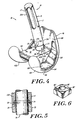
- FIG. 4 is an assembled view of the modular knee prosthesis of FIG. 1.
- FIG. 5 is a detailed view, partly in cross-section, of the stem member and collar components of the knee prosthesis of FIG. 1.
- FIG. 6 is a perspective view of an alternate embodiment of a washer useful with the invention.
- the modular knee prosthesis 10 of the invention includes a femoral stem 14, a collar 26, a femoral component 40, a washer 80, and a securing bolt 70.
- Components of the illustrated modular knee prosthesis 10 are suitable for use in both right and left side prostheses.
- the femoral component 40 has a pair of spaced condylar portions 42A, 42B that are connected by an intercondylar boss structure 44.
- the femoral component 40 has a superior articulation surface 45 and an opposed inferior surface 46.
- the femoral component 40 has a posterior side 36 and an anterior side 38.
- the anterior side 38 of the femoral component 40 includes a patellar groove 54, which seats a patellar prosthetic component (not shown).
- the superior surfaces 45 of the curved condylar portions 42A, 42B articulate with a prosthetic tibial component (not shown) mounted on the head of the tibia, in a manner well known in the art.
- the boss structure 44 has a pair of substantially vertical side walls 44A that are generally orthogonal to a top, inferior surface 44B and a bottom superior surface 44C.
- the top surface 44B is substantially horizontally oriented and extends in the transverse plane.
- the boss 44 further has a cavity 48 that is formed within the bottom superior surface 44C.
- the cavity 48 has a substantially rectangular shape and has a pair of medial-lateral side walls 52 and a pair of anterior-posterior side walls 53.
- the cavity further includes a substantially flat endwall 56 that seats the top surface 82 of the washer 80.
- An elongated aperture 50 preferably elongated in the anterior-posterior direction, is formed in the endwall 56 of cavity 48 and extends between the superior and inferior surfaces 45, 46 of the boss structure 44. As illustrated in FIG. 3, and as shown in phantom in FIG. 1, the cavity extends in the direction of the aperture to allow a bolt to move easily within the aperture.
- the shape of the aperture can be elliptical; oval, spherical, or of any other suitable shape that allows a sufficient amount of translation of the bolt shaft 74 of the bolt when the bolt is mounted within the aperture 50.
- the transverse plane is defined as the horizontal plane that extends through the knee of an upright subject and that is orthogonal to both the coronal plane and the sagittal plane, as will be appreciated by those having ordinary skill in the art.
- the elongated shape of the cavity 48 and of the aperture 50 provide sufficient space for the bolt shaft 74 to translate therealong in the anterior-posterior direction. This freedom of movement of the bolt 70 within the aperture 50 in the transverse plane provides a virtually infinite number of mounting positions for the stem assembly, e.g., the stem member 14 and the collar 26.
- the endwall 56 of the cavity 48 has formed thereon a series of surface features 58, e.g., grooves or protrusions, that preferably extend in the medial-lateral direction and are spaced in the anterior-posterior direction.
- the surface feature 58 of the boss structure 44 cooperates with another, complementary surface feature 84 formed on the top surface 82 of the mating element, e.g., the washer 80, to position the stem 14 at one of the mounting positions, as described further below.
- the surface feature 58 of the boss 44 can be in the form of an indentation or a raised structure that is located on either the inferior or superior surface 46, 45 of the boss 44. It is understood that surface features 58, 84 are intended to be complementary.
- surface feature 84 will be in the form of a protrusion dimensioned to fit within the grooves.
- end wall of the femoral component of the drawings includes three grooves, those of ordinary skill in the art will recognize that any number of grooves can be formed in the boss superior surface.
- the inferior surface 46 of the boss 44 has position indicia 60 at locations relative to the surface feature 58 formed on the boss superior surface 45.
- the position markings 60 visually indicate one or more mounting positions in the transverse plane.
- the collar 26 includes a position marking 23 that cooperates with the boss position indicia 60 to visually indicate the mounting position of the stem assembly in the transverse plane.
- the illustrated boss indicia 60 preferably include a linear succession of lines 62A-62C that represent different spatial stem mounting locations.
- line 62B can be used to indicate that a stem is mounted without offset.
- Line 62A can be used to indicate a stem mounting which is offset by 2 mm in the posterior direction.
- line 62C can be used to indicate a stem mounting which is offset by 2 mm in the anterior direction.
- the position indicia 60 visually indicate the mounting position of the femoral stem.
- any number of position indicia can be formed on the inferior surface 46, and that each indicia marking corresponds to a different femoral stem mounting position.
- the inferior surface 46 of the condylar portions 42A, 42B includes a series of connected integral surfaces that extend between the anterior and posterior sides of the femoral component 40.
- the inferior surface 46 of each condylar portion 42A and 42B comprises an anterior flange 100, an anterior chamfer 102, a substantially horizontal surface 104, a posterior chamfer 106, and a posterior flange 108.
- the horizontal surface 104 of each condylar portion 42A, 42B has an indentation 110 that extends partly into the inferior surface 46 of each condylar portion.
- the indentation 110 allows the surgeon to grasp and handle the femoral component 40 via a suitable handling instrument.
- FIGS. and 6 illustrate the washer 80 useful with the present invention.
- the washer 80 includes a top portion 82 and an opposed bottom portion 86.
- a non-threaded central aperture 88 extends between the top and bottom surfaces.
- a surface feature 84 e.g., a detent, is formed on at least one of the washer surfaces, e.g., the top surface 82.
- the surface feature 84 is preferably located at a substantially centrally located position on the washer top surface 82, and cooperates with the surface feature 58 of the boss to position the femoral stem 14 at a selected mounting position within the transverse plane, and to prevent the femoral stem assembly from slipping from the desired mounting position.
- the central location of the raised surface feature 84 allows the washer 80 to seat easily in one of the surface features 58 formed along the endwall 56 of the boss.
- the detent 84 can be mounted within the posterior-most groove, e.g., groove 58B.
- the detent 84 can be mounted within the anterior-most groove, e.g, groove 58A.
- the washer can be any conventional biocompatible mechanical washer, and can be composed of a cobalt/chromium or titanium alloy, stainless steel, ultra-high molecular weight polyethylene, or high density polyethylene.
- the raised surface feature 84' can be formed at a non-centrally located position, as illustrated in FIG. 6. As illustrated surface feature 84' is formed at an offset position measured relative to the central aperture 88' of the washer 80'. Similar to the washer 80 of FIG. 1, the offset surface feature 84' of the washer 80' allows the washer to seat at one of a plurality of mounting positions defined by the indented surface feature 58 formed in the endwall 56 of the boss 44.
- the offset surface feature 84' provides for plural mounting positions in the anterior-posterior direction by simply rotating the washer 80' to align the surface feature 84' with the indented surface feature 58 located at the desired position.
- the surface features 84 and 84' can thus be formed at selected locations on the washer that optimize placement of the femoral stem in the transverse plane at a series of desired stem mounting locations.
- the offset surface feature 84' is particularly useful in modular knee prostheses that provide only a single indented surface feature 58 on the endwall 56 of the boss structure 44.
- the offset surface feature 84' cooperates with the single indented feature to form multiple mounting positions.
- the washer 80' contains an offset surface feature 84' on a first surface and a non-offset surface feature 84 on the opposing surface. This construction enables a single washer to position the femoral stem at least at three locations in the transverse plane, e.g., at 0 mm offset and at the 2 mm anterior and posterior offset positions.
- the femoral stem 14 can be positioned at three or more positions in the transverse plane.
- the washer 80 contains an indented surface feature such as a groove rather than a raised surface feature such as a detent.
- a groove can be positioned at either or both the offset and non-offset locations.
- the endwall 56 of the boss structure 44 has formed thereon a linear series of raised surface features sized to seat within the washer groove.
- the elongated aperture 50, grooves 58 and washer detent 84 cooperate to optimize the stem location within the intramedullary canal of the femur by allowing the surgeon to select the proper mounting position for the stem assembly.
- the ability to optimize the stem location ensures that the proper mechanical stresses are transferred along the femur, without overloading a particular portion of bone. Additionally, the proper alignment of the stem assembly with the femoral component ensures that the condyles properly contact and articulate with the tibial bearing member.
- the illustrated securing bolt 70 preferably includes a head portion 72 having a washer-engaging surface 78 and a shaft portion 74 that extends outwardly therefrom.
- the shaft portion 74 preferably has an unthreaded shaft portion 75 disposed adjacent to the head portion 72, and an upper, threaded portion 76 disposed adjacent to the unthreaded portion 75.
- the unthreaded shaft portion 75 preferably has an outer diameter that is less than the outer diameter of the head portion 72.
- the upper, threaded portion 76 preferably has a diameter equal to or less than the diameter of the unthreaded portion 75.
- the collar 26 has a main body that includes a distal portion 28 and an adjacent proximal portion 29 which has a threaded outer surface.
- the proximal portion 29 is preferably sized to mate with femoral stems 14 having various diameters, including diameters of between about 10 mm and about 24 mm.
- the distal portion 28 of the collar has an anti-rotation protrusion 30 that extends downwardly from a boss-engaging surface 32.
- the anti-rotation protrusion 30 preferably seats in an appropriate cut-out section 16 that is formed within the boss aperture 50, as shown in FIG. 2.
- the anti-rotation protrusion 30 seats within the aperture to prevent unwanted rotation of the collar 26 when the femoral stem 14 is tightened on the bolt shaft 74.
- This feature is desirable since it enables the collar to be locked in a selected position and location during assembly of the knee joint components.
- the protrusion 30 can also be formed as an indented surface feature.
- the collar 26 further includes a circumferential slot 34 that, in conjunction with a slot 20 formed along the inner portion of the stem 14, seats a lock ring 18 in the manner illustrated in FIG. 5.
- the lock ring secures the stem 14 to the collar 26 when the two components are assembled together.
- a central aperture 31 within collar 26 is sized to seat the bolt shaft 74 and allows the bolt shaft to pass therethrough.
- the collar 26 further includes position marking 23 formed on the outer surface of the collar distal portion 28.
- the position marking 23 in conjunction with the position indicia 60 of the boss 44 visually indicate the mounting position, in the transverse plane, of the femoral stem assembly. Specifically, aligning the position marking 23 with one of the position indicia 60 formed on the inferior surface 46 of the boss structure 44, as shown in FIG. 4, indicates whether the stem assembly is positioned in the anterior direction, the posterior direction, or at an intermediate position, in the transverse plane.
- aligning the position marking 23 of the collar with position marking 62A positions the femoral stem assembly in the posterior direction in the transverse plane.
- aligning the position marking 23 with the marking 62C positions the stem assembly in the anterior direction.
- the position marking 62B preferably represents an intermediate, no-offset position.
- a significant advantage of providing the position markings on the collar 26 and the boss structure 40 is that they allow the surgeon, at a glance, to choose a desired mounting position for the stem 14, while concomitantly providing a flexible knee prosthesis for which immediate stem adjustments can be made in the course of surgical procedures.
- the collar 26 further includes orientation indicia 24 formed on the outer distal portion 28 of the collar 26 at a location circumferentially spaced from the position marking 23.
- the orientation indicia 24 cooperate with orientation markings 22 formed on the stem 14 to indicate the relative position of the femoral stem 14 in the sagittal plane. This feature of the invention is discussed in further detail below.
- the femoral stem 14 has an elongate body 15 that extends along a longitudinal axis.
- a series of circumferentially spaced flutes 17 are formed along a proximal portion 15A of the body 15.
- the flutes 17 inhibit rotation of the stem within the medullary canal of the femur.
- the distal portion 15B of the stem body 15 further has a collar and bolt-receiving aperture 19 that seats the proximal portion 29 of the collar 26 and the portion of the bolt shaft 74 that extends beyond the proximal surface 29 of collar 26 (see FIG. 5).
- the aperture 19 preferably has a threaded portion, on an interior wall thereof, that mates with a threaded portion 76 of the bolt shaft 74.
- the stem 14 is preferably curved along the length of the stem main body 15 to simulate the natural bow of the human femur.
- the stem can be formed with a variety of curvatures to accommodate differing patient anatomies.
- the femoral stem is also suitable for use, without modification, in both left and right side prostheses.
- the femoral stem 14 also includes orientation markings 22 which help indicate the relative position of the curved stem member in the sagittal plane.
- Markings 22 preferably include a plurality of vertical lines that represent separate discrete spatial positions. As illustrated in FIG. 4, a longer central line 22A is disposed between a pair of shorter vertical lines 22B. The longer central line preferably indicates the position of the stem relative to the collar 26.
- the stem orientation markings 22 are preferably used in conjunction with the collar orientation indicia 24 to positively and easily position the femoral stem 14 in a selected position in the sagittal plane.
- the central line 22A can be aligned with one of the orientation indicia 24 of the collar to orient the stem at a selected location.
- the stem position in the sagittal plane can be easily changed by aligning the orientation marking 22 with different ones of the orientation indicia 24. This feature allows the surgeon to utilize curved, as well as straight, femoral stem members.
- the knee prosthesis of the invention is assembled as follows. First, the washer 80 is disposed within the elongated cavity 48 formed in the superior surface 45 of the boss structure 44.
- the surface feature 84, formed on the top surface 82 of the washer 80, is then aligned with one of the surface features 58 formed in the cavity endwall.
- the surface features 58 are adjacent an elongated aperture 50 that extends between the inferior and superior surfaces of the boss.
- the femoral stem 14 and the collar 26 are secured together by the lock ring 18 at the manufacturing site. This pre-assembly of selected components is desirable since it reduces the number of parts that the surgeon has to assemble during the surgical procedure.
- the collar 26 is then mounted on the inferior surface 46 of the boss structure 44 at a desired location in the transverse plane, corresponding to the location of the washer 80, by aligning the position markings 23 formed on the collar 23 with one of the appropriate positioning indicia 60 formed on the boss.
- the positioning indicia 60 and position markings 23 cooperate to indicate the desired mounting position of the stem assembly.
- the mounting position can be adjusted by simply placing the surface feature 84 of the washer in a different indented surface feature, and by visually aligning the position marking 23 of the collar with the corresponding position indicia 60.
- the anti-rotation protrusion 30 of the collar 26 preferably seats within the cut-out section 16 formed within the boss aperture 50 to prevent unwanted rotation of the collar during assembly.
- the cut-out section 16 preferably is oriented such that it is elongated in the anterior-posterior direction and opens onto the central boss aperture 50 to allow the collar 26 to mount at one of the plurality of mounting locations.
- the distal portion 15B of the femoral stem 14 is then placed over the proximal portion of the collar 26.
- the proximal portion of the collar seats within the receiving end, e.g., distal end, of the stem, but is not rigidly captured therein.
- the stem at least initially, is rotatable about the stem axis independent of the collar. This allows the stem to be properly positioned at a desired orientation in the sagittal plane, indicated by the orientation indicia formed on the collar 24 and the stem 22. Independent rotation of the stem enables the stem and/or collar to remain properly positioned.
- the bolt 70 is then inserted from the superior side of the femoral component 40 through the washer aperture 88, the boss aperture 50, and into the collar central aperture 31.
- the portion of the bolt shaft 74 that extends beyond the proximal end 29 of the collar is captured within the receiving aperture 19 formed in the distal portion 15B of the stem 14.
- the modular knee prosthesis of the invention thus provides an easy and effective technique for the surgeon to quickly and readily tailor the modular knee prosthesis to the patient.
- the prosthesis of the invention further provides a prosthesis that provides multiple positioning of the stem assembly in the transverse plane and multiple positioning of the curved stem in the sagittal plane, while reducing the overall piece count of the system.
Description
- This invention relates to implantable joint prostheses, and more particularly to femoral stem assemblies for use with modular knee joint prostheses employed during knee arthroplasty procedures.
- Knee arthroplasty is a well known surgical procedure by which a diseased and/or damaged natural knee joint is replaced by a prosthetic knee joint. Typical knee prostheses include a tibial component, a femoral component, a femoral stem assembly and a patellar component. The femoral component generally includes a pair of spaced apart condylar portions, the superior surfaces of which articulate with a portion of the tibial component. The femoral stem assembly provides lateral stability to the replaced knee joint, and typically includes a member that mounts within the medullary canal of a distal portion of a femur. The stem is typically coupled to the femoral component by a specialized collar and bolt.
- Knee joint prostheses are available as modular assemblies to reduce the number of individual components that must be purchased and stocked, and to reduce the associated component handling time by a surgeon during the arthroplasty procedure. An example of a prior art modular knee prosthesis is described in U.S. Patent No. 5,152,796 (Slamin). The Slamin patent describes a modular knee prosthesis that includes a femoral component and a series of bolts that attach to and extend from the femoral component at various angles corresponding to different valgus angles. The valgus angle is defined as the angle between the center line of the femur and the vertical axis connecting the distal femur and the center of the femoral head. Typical valves of the valgus angle are between 5° and 9°. The prosthesis also includes a
- Another modular knee prosthesis is disclosed in EP-0714645, which was filed before but published after the priority data of the present invention. Yet another is disclosed in EP 0531263, the contents of which form the basis of the preamble of claim 1, appended hereto. EP 0531263 discloses a knee prosthesis having a ball joint therein for providing adjustability.
- Despite existing modular knee joint prostheses, there remains a need for a modular knee joint prosthesis that has sufficient versatility to accommodate differing patient anatomy and joint conditions. Many modern modular knee prostheses are characterized by a large number of components with little or no part interchangeability. Such systems tend to increase purchasing costs because of part waste. Additionally, the numerous parts must be handled and stocked, thus increasing costs associated with inventory control and management.
- Another drawback of some existing modular knee prostheses is that they provide insufficient versatility to accommodate differing patient anatomies. Patients typically have different femoral anatomies and thus require stems of different sizes and curvatures. Additionally, the mounting location or origination point of the stem relative to the femoral component varies among patients. Many known modular knee systems attempt to overcome these drawbacks by utilizing specialized parts and related mounting hardware. These specialized parts, however, add to the overall piece count and cost of the system. Such items risk complicating the surgical procedure due to the time required to assemble the artificial knee joint.
- It is thus an object of the invention to provide a modular knee prosthesis having sufficient versatility to accommodate various patient anatomies and joint conditions while maintaining a relatively low component piece count. It is another object of the invention to provide a modular knee prosthesis having components that are physiologically and geometrically compatible with different patient anatomical geometries and conditions. Still another object of the invention is to provide a modular knee prosthesis that can accommodate different femoral stems. Yet another object of the invention is to provide a modular knee prosthesis that can vary the origination point of the femoral stem relative to the femoral component during the surgical procedure. A further object of the invention is to provide a modular knee prosthesis that is relatively easy to use. Other general and more specific objects of the invention will in part be apparent from the drawings and description which follow.
- The present invention relates to a modular knee joint prosthesis having improved versatility while reducing the overall component piece count as defined in claim 1. Components of the modular prosthesis of the invention are able to be used with both right and left side prostheses.
- The modular knee prosthesis of the invention includes a femoral component having a pair of laterally spaced apart condylar portions each having a superior, articulation surface and an inferior surface. A boss structure is disposed between and connects the condylar portions. The boss structure has an inferior surface that is generally horizontally oriented in the transverse plane, and an opposed superior surface. An aperture, formed in the boss structure, extends between the inferior and superior surfaces thereof. The prosthesis further includes a bolt having head and shaft portions, an elongate stem member, and appropriate positioning structure.
- The positioning structure locates the femoral stem at one or more mounting positions in the transverse plane. The mounting positions are defined as those positions formed along the boss aperture in the transverse plane, and spaced apart from each other in the anterior-posterior direction, where the stem assembly is secured, by an appropriate securing structure, to the femoral component. Thus, the aperture, which preferably is elongated, provides a potentially infinite number of discrete origination points in the transverse plane. The term "origination point" is intended to mean the point on the inferior surface of the boss structure from which the bolt shaft protrudes when mounted in the aperture of the femoral component.
- According to one aspect, the positioning structure comprises one or more surface features that are formed on the boss structure and a mating element that is directly or indirectly matable with the femoral stem. The mating element has at least one surface feature that is engageable and interlockable with the surface feature of the boss. According to one embodiment, the boss surface feature comprises one or more grooves and the mating element, e.g., a washer, has a detent that is adapted to seat in one of the grooves. The grooves preferably extend in the medial-lateral direction and are spaced apart from one another in the anterior-posterior direction.
- According to another aspect of the invention, the boss structure includes position indicia formed on the inferior surface of the boss structure. The positioning indicia provide a visual indication of at least some of the mounting positions of the femoral stem.
- According to another aspect, the modular knee prosthesis includes a collar having a proximal end for mounting to the distal end of the femoral stem member and a distal end for mounting on the inferior surface of the boss structure. The collar has position markings that cooperate with the positioning indicia of the boss structure to visually indicate the femoral stem mounting position.
- According to still another aspect, the collar and stem include orientation indicia, which cooperate to visually indicate the position in the sagittal plane of a curved femoral stem member. The knee prosthesis of the invention accommodates differing patient anatomies by allowing a curved femoral stem to be affixed in a selected position relative to the patient's femur. Thus, a surgeon can tailor the modular prosthesis to be compatible with a patient's unique anatomy by first selecting the desired orientation of the stem member via the orientation indicia, and then positioning the stem assembly in the transverse plane at the appropriate mounting position by way of the positioning indicia.
- Although illustrated as a modular unit, those of ordinary skill will recognize that the individual components of the assembly can be provided separately.
- The foregoing and other objects, features and advantages of the invention will be apparent from the following description and the accompanying drawings, in which like reference characters refer to the same parts throughout the different views.
- FIG. 1 is an exploded perspective view of a modular knee prosthesis according to the present invention.
- FIG. 2 is a plan view of the inferior surface of the femoral component of FIG. 1.
- FIG. 3 is a plan view of the superior articulation surface of the femoral component of FIG. 1.
- FIG. 4 is an assembled view of the modular knee prosthesis of FIG. 1.
- FIG. 5 is a detailed view, partly in cross-section, of the stem member and collar components of the knee prosthesis of FIG. 1.
- FIG. 6 is a perspective view of an alternate embodiment of a washer useful with the invention.
- As illustrated in FIG. 1, the
modular knee prosthesis 10 of the invention includes afemoral stem 14, acollar 26, afemoral component 40, awasher 80, and a securingbolt 70. Components of the illustratedmodular knee prosthesis 10 are suitable for use in both right and left side prostheses. - Referring to FIGS. 1 through 3, the
femoral component 40 has a pair of spacedcondylar portions 42A, 42B that are connected by anintercondylar boss structure 44. Thefemoral component 40 has a superior articulation surface 45 and an opposedinferior surface 46. Further, thefemoral component 40 has aposterior side 36 and ananterior side 38. Theanterior side 38 of thefemoral component 40 includes apatellar groove 54, which seats a patellar prosthetic component (not shown). The superior surfaces 45 of thecurved condylar portions 42A, 42B articulate with a prosthetic tibial component (not shown) mounted on the head of the tibia, in a manner well known in the art. - The
boss structure 44 has a pair of substantiallyvertical side walls 44A that are generally orthogonal to a top, inferior surface 44B and a bottom superior surface 44C. The top surface 44B is substantially horizontally oriented and extends in the transverse plane. Theboss 44 further has acavity 48 that is formed within the bottom superior surface 44C. Thecavity 48 has a substantially rectangular shape and has a pair of medial-lateral side walls 52 and a pair of anterior-posterior side walls 53. The cavity further includes a substantiallyflat endwall 56 that seats thetop surface 82 of thewasher 80. - An
elongated aperture 50, preferably elongated in the anterior-posterior direction, is formed in theendwall 56 ofcavity 48 and extends between the superior andinferior surfaces 45, 46 of theboss structure 44. As illustrated in FIG. 3, and as shown in phantom in FIG. 1, the cavity extends in the direction of the aperture to allow a bolt to move easily within the aperture. The shape of the aperture can be elliptical; oval, spherical, or of any other suitable shape that allows a sufficient amount of translation of thebolt shaft 74 of the bolt when the bolt is mounted within theaperture 50. - The transverse plane is defined as the horizontal plane that extends through the knee of an upright subject and that is orthogonal to both the coronal plane and the sagittal plane, as will be appreciated by those having ordinary skill in the art.
- The elongated shape of the
cavity 48 and of theaperture 50 provide sufficient space for thebolt shaft 74 to translate therealong in the anterior-posterior direction. This freedom of movement of thebolt 70 within theaperture 50 in the transverse plane provides a virtually infinite number of mounting positions for the stem assembly, e.g., thestem member 14 and thecollar 26. - The
endwall 56 of thecavity 48 has formed thereon a series of surface features 58, e.g., grooves or protrusions, that preferably extend in the medial-lateral direction and are spaced in the anterior-posterior direction. Thesurface feature 58 of theboss structure 44 cooperates with another,complementary surface feature 84 formed on thetop surface 82 of the mating element, e.g., thewasher 80, to position thestem 14 at one of the mounting positions, as described further below. Thesurface feature 58 of theboss 44 can be in the form of an indentation or a raised structure that is located on either the inferior orsuperior surface 46, 45 of theboss 44. It is understood that surface features 58, 84 are intended to be complementary. Thus, if surface features 58 are in the form of grooves,surface feature 84 will be in the form of a protrusion dimensioned to fit within the grooves. Although the end wall of the femoral component of the drawings includes three grooves, those of ordinary skill in the art will recognize that any number of grooves can be formed in the boss superior surface. - With reference to FIGS. 1 through 4, and particularly to FIG. 4, the
inferior surface 46 of theboss 44 hasposition indicia 60 at locations relative to thesurface feature 58 formed on the boss superior surface 45. Theposition markings 60 visually indicate one or more mounting positions in the transverse plane. According to one practice, thecollar 26 includes a position marking 23 that cooperates with the boss position indicia 60 to visually indicate the mounting position of the stem assembly in the transverse plane. - The illustrated
boss indicia 60 preferably include a linear succession oflines 62A-62C that represent different spatial stem mounting locations. For example, line 62B can be used to indicate that a stem is mounted without offset.Line 62A can be used to indicate a stem mounting which is offset by 2 mm in the posterior direction. Likewise,line 62C can be used to indicate a stem mounting which is offset by 2 mm in the anterior direction. Thus, the position indicia 60 visually indicate the mounting position of the femoral stem. One having ordinary skill will readily appreciate that any number of position indicia can be formed on theinferior surface 46, and that each indicia marking corresponds to a different femoral stem mounting position. - The
inferior surface 46 of thecondylar portions 42A, 42B includes a series of connected integral surfaces that extend between the anterior and posterior sides of thefemoral component 40. Referring to FIGS. 1, 2 and 4, theinferior surface 46 of eachcondylar portion 42A and 42B comprises ananterior flange 100, ananterior chamfer 102, a substantiallyhorizontal surface 104, aposterior chamfer 106, and aposterior flange 108. Thehorizontal surface 104 of eachcondylar portion 42A, 42B has anindentation 110 that extends partly into theinferior surface 46 of each condylar portion. Theindentation 110 allows the surgeon to grasp and handle thefemoral component 40 via a suitable handling instrument. - FIGS. and 6 illustrate the
washer 80 useful with the present invention. Thewasher 80 includes atop portion 82 and anopposed bottom portion 86. A non-threadedcentral aperture 88 extends between the top and bottom surfaces. Asurface feature 84, e.g., a detent, is formed on at least one of the washer surfaces, e.g., thetop surface 82. Thesurface feature 84 is preferably located at a substantially centrally located position on thewasher top surface 82, and cooperates with thesurface feature 58 of the boss to position thefemoral stem 14 at a selected mounting position within the transverse plane, and to prevent the femoral stem assembly from slipping from the desired mounting position. - In the embodiment of FIG. 1, the central location of the raised
surface feature 84 allows thewasher 80 to seat easily in one of the surface features 58 formed along theendwall 56 of the boss. For example, as illustrated in FIG. 3, if it is desirable to locate thewasher 80 in the posterior direction, thedetent 84 can be mounted within the posterior-most groove, e.g., groove 58B. Similarly, if it is desirable to mount the washer in the anterior-most direction, thedetent 84 can be mounted within the anterior-most groove, e.g,groove 58A. The washer can be any conventional biocompatible mechanical washer, and can be composed of a cobalt/chromium or titanium alloy, stainless steel, ultra-high molecular weight polyethylene, or high density polyethylene. - In an alternative embodiment, the raised surface feature 84' can be formed at a non-centrally located position, as illustrated in FIG. 6. As illustrated surface feature 84' is formed at an offset position measured relative to the central aperture 88' of the washer 80'. Similar to the
washer 80 of FIG. 1, the offset surface feature 84' of the washer 80' allows the washer to seat at one of a plurality of mounting positions defined by theindented surface feature 58 formed in theendwall 56 of theboss 44. The offset surface feature 84' provides for plural mounting positions in the anterior-posterior direction by simply rotating the washer 80' to align the surface feature 84' with theindented surface feature 58 located at the desired position. The surface features 84 and 84' can thus be formed at selected locations on the washer that optimize placement of the femoral stem in the transverse plane at a series of desired stem mounting locations. - The offset surface feature 84' is particularly useful in modular knee prostheses that provide only a single
indented surface feature 58 on theendwall 56 of theboss structure 44. The offset surface feature 84' cooperates with the single indented feature to form multiple mounting positions. In one embodiment of the invention, the washer 80' contains an offset surface feature 84' on a first surface and anon-offset surface feature 84 on the opposing surface. This construction enables a single washer to position the femoral stem at least at three locations in the transverse plane, e.g., at 0 mm offset and at the 2 mm anterior and posterior offset positions. When multiple indented surface features are formed on theendwall 56, thefemoral stem 14 can be positioned at three or more positions in the transverse plane. - According to another embodiment of the invention, the
washer 80 contains an indented surface feature such as a groove rather than a raised surface feature such as a detent. Such a groove can be positioned at either or both the offset and non-offset locations. In this embodiment, theendwall 56 of theboss structure 44 has formed thereon a linear series of raised surface features sized to seat within the washer groove. Those of ordinary skill in the art will readily recognize that other suitable permutations to the illustrated washer design exist. - The
elongated aperture 50,grooves 58 andwasher detent 84 cooperate to optimize the stem location within the intramedullary canal of the femur by allowing the surgeon to select the proper mounting position for the stem assembly. The ability to optimize the stem location ensures that the proper mechanical stresses are transferred along the femur, without overloading a particular portion of bone. Additionally, the proper alignment of the stem assembly with the femoral component ensures that the condyles properly contact and articulate with the tibial bearing member. - With reference to FIG. 1, the illustrated securing
bolt 70 preferably includes a head portion 72 having a washer-engagingsurface 78 and ashaft portion 74 that extends outwardly therefrom. Theshaft portion 74 preferably has an unthreadedshaft portion 75 disposed adjacent to the head portion 72, and an upper, threadedportion 76 disposed adjacent to the unthreadedportion 75. The unthreadedshaft portion 75 preferably has an outer diameter that is less than the outer diameter of the head portion 72. The upper, threadedportion 76 preferably has a diameter equal to or less than the diameter of the unthreadedportion 75. - The
collar 26 has a main body that includes adistal portion 28 and an adjacentproximal portion 29 which has a threaded outer surface. Theproximal portion 29 is preferably sized to mate with femoral stems 14 having various diameters, including diameters of between about 10 mm and about 24 mm. Thedistal portion 28 of the collar has ananti-rotation protrusion 30 that extends downwardly from a boss-engagingsurface 32. Theanti-rotation protrusion 30 preferably seats in an appropriate cut-outsection 16 that is formed within theboss aperture 50, as shown in FIG. 2. For example, when the boss-engagingsurface 32 of thecollar 26 is placed in contact with the bossinferior surface 46, theanti-rotation protrusion 30 seats within the aperture to prevent unwanted rotation of thecollar 26 when thefemoral stem 14 is tightened on thebolt shaft 74. This feature is desirable since it enables the collar to be locked in a selected position and location during assembly of the knee joint components. Those of ordinary skill will appreciate that theprotrusion 30 can also be formed as an indented surface feature. - The
collar 26 further includes acircumferential slot 34 that, in conjunction with aslot 20 formed along the inner portion of thestem 14, seats alock ring 18 in the manner illustrated in FIG. 5. The lock ring secures thestem 14 to thecollar 26 when the two components are assembled together. Acentral aperture 31 withincollar 26 is sized to seat thebolt shaft 74 and allows the bolt shaft to pass therethrough. - With reference to FIGS. 1 and 4, the
collar 26 further includes position marking 23 formed on the outer surface of the collardistal portion 28. The position marking 23 in conjunction with the position indicia 60 of theboss 44 visually indicate the mounting position, in the transverse plane, of the femoral stem assembly. Specifically, aligning the position marking 23 with one of the position indicia 60 formed on theinferior surface 46 of theboss structure 44, as shown in FIG. 4, indicates whether the stem assembly is positioned in the anterior direction, the posterior direction, or at an intermediate position, in the transverse plane. - By way of example, aligning the position marking 23 of the collar with position marking 62A positions the femoral stem assembly in the posterior direction in the transverse plane. Similarly, aligning the position marking 23 with the marking 62C positions the stem assembly in the anterior direction. The position marking 62B preferably represents an intermediate, no-offset position.
- A significant advantage of providing the position markings on the
collar 26 and theboss structure 40 is that they allow the surgeon, at a glance, to choose a desired mounting position for thestem 14, while concomitantly providing a flexible knee prosthesis for which immediate stem adjustments can be made in the course of surgical procedures. - The
collar 26 further includesorientation indicia 24 formed on the outerdistal portion 28 of thecollar 26 at a location circumferentially spaced from the position marking 23. The orientation indicia 24 cooperate withorientation markings 22 formed on thestem 14 to indicate the relative position of thefemoral stem 14 in the sagittal plane. This feature of the invention is discussed in further detail below. - Referring again to FIGS. 1 and 4, the
femoral stem 14 has anelongate body 15 that extends along a longitudinal axis. A series of circumferentially spacedflutes 17 are formed along aproximal portion 15A of thebody 15. Theflutes 17 inhibit rotation of the stem within the medullary canal of the femur. The distal portion 15B of thestem body 15 further has a collar and bolt-receivingaperture 19 that seats theproximal portion 29 of thecollar 26 and the portion of thebolt shaft 74 that extends beyond theproximal surface 29 of collar 26 (see FIG. 5). Theaperture 19 preferably has a threaded portion, on an interior wall thereof, that mates with a threadedportion 76 of thebolt shaft 74. - The
stem 14 is preferably curved along the length of the stemmain body 15 to simulate the natural bow of the human femur. The stem can be formed with a variety of curvatures to accommodate differing patient anatomies. The femoral stem is also suitable for use, without modification, in both left and right side prostheses. - As noted above, the
femoral stem 14 also includesorientation markings 22 which help indicate the relative position of the curved stem member in the sagittal plane.Markings 22 preferably include a plurality of vertical lines that represent separate discrete spatial positions. As illustrated in FIG. 4, a longercentral line 22A is disposed between a pair of shorter vertical lines 22B. The longer central line preferably indicates the position of the stem relative to thecollar 26. Thestem orientation markings 22 are preferably used in conjunction with thecollar orientation indicia 24 to positively and easily position thefemoral stem 14 in a selected position in the sagittal plane. For example, thecentral line 22A can be aligned with one of the orientation indicia 24 of the collar to orient the stem at a selected location. Thus, the stem position in the sagittal plane can be easily changed by aligning the orientation marking 22 with different ones of theorientation indicia 24. This feature allows the surgeon to utilize curved, as well as straight, femoral stem members. - The knee prosthesis of the invention is assembled as follows. First, the
washer 80 is disposed within theelongated cavity 48 formed in the superior surface 45 of theboss structure 44. Thesurface feature 84, formed on thetop surface 82 of thewasher 80, is then aligned with one of the surface features 58 formed in the cavity endwall. The surface features 58 are adjacent anelongated aperture 50 that extends between the inferior and superior surfaces of the boss. - According to a preferred practice, the
femoral stem 14 and thecollar 26 are secured together by thelock ring 18 at the manufacturing site. This pre-assembly of selected components is desirable since it reduces the number of parts that the surgeon has to assemble during the surgical procedure. - The
collar 26 is then mounted on theinferior surface 46 of theboss structure 44 at a desired location in the transverse plane, corresponding to the location of thewasher 80, by aligning theposition markings 23 formed on thecollar 23 with one of theappropriate positioning indicia 60 formed on the boss. The positioning indicia 60 andposition markings 23 cooperate to indicate the desired mounting position of the stem assembly. The mounting position can be adjusted by simply placing thesurface feature 84 of the washer in a different indented surface feature, and by visually aligning the position marking 23 of the collar with the corresponding position indicia 60. - The
anti-rotation protrusion 30 of thecollar 26 preferably seats within the cut-outsection 16 formed within theboss aperture 50 to prevent unwanted rotation of the collar during assembly. The cut-outsection 16 preferably is oriented such that it is elongated in the anterior-posterior direction and opens onto thecentral boss aperture 50 to allow thecollar 26 to mount at one of the plurality of mounting locations. - The distal portion 15B of the
femoral stem 14 is then placed over the proximal portion of thecollar 26. In this assembly, the proximal portion of the collar seats within the receiving end, e.g., distal end, of the stem, but is not rigidly captured therein. Thus, the stem, at least initially, is rotatable about the stem axis independent of the collar. This allows the stem to be properly positioned at a desired orientation in the sagittal plane, indicated by the orientation indicia formed on thecollar 24 and thestem 22. Independent rotation of the stem enables the stem and/or collar to remain properly positioned. - When the desired stem mounting position in the transverse plane and the desired orientation in the sagittal plane are selected, the
bolt 70 is then inserted from the superior side of thefemoral component 40 through thewasher aperture 88, theboss aperture 50, and into the collarcentral aperture 31. The portion of thebolt shaft 74 that extends beyond theproximal end 29 of the collar is captured within the receivingaperture 19 formed in the distal portion 15B of thestem 14. When thebolt 70 is tightened, thestem 14 and the bolt head 72 are drawn together until thecollar 26 is secured between thestem 14 and theboss structure 44. - The modular knee prosthesis of the invention thus provides an easy and effective technique for the surgeon to quickly and readily tailor the modular knee prosthesis to the patient. The prosthesis of the invention further provides a prosthesis that provides multiple positioning of the stem assembly in the transverse plane and multiple positioning of the curved stem in the sagittal plane, while reducing the overall piece count of the system.
- It will thus be seen that the invention efficiently attains the objects set forth above, among those made apparent from the preceding description. Since certain changes may be made in the above constructions without departing from the scope of the invention as defined by the appended claims, it is intended that all matter contained in the above description or shown in the accompanying drawings be interpreted as illustrative and not in a limiting sense.
Claims (21)
- A modular knee prosthesis (10) comprising:wherein the stem member (14) has an open distal end (19) for mounting to the boss structure (44).a femoral component (4) having a pair of spaced apart condylar portions (42A, 42B), each having a distal articulation surface (45) and a proximal surface (46), the femoral component (4) further includinga boss structure (44) disposed between and connecting the condylar portions (42A, 42B) of the femoral component (40), the boss structure (44) having a proximal surface (44B) that is generally horizontally oriented in a transverse plane, and an opposed distal surface (44C),an aperture (50) extending between the distal and proximal surfaces (44B, 44C) of the boss structure (44), and an elongate stem member (14) for mounting within the medullary canal of a distal portion of a femur, the stem member having a proximal end; characterised in that the prosthesis (10) further comprises:first positioning means (58) formed on at least one surface (56) of the boss structure (44), adjacent the aperture (50), defining one or more transverse plane mounting positions for a femoral stem member (14);a washer element (80) having a main body and an aperture (88) extending therethrough, said washer element (80), in use, being mountable upon the distal surface (44C) of the boss structure (44) and having second positioning means (84) for co-operating with the first positioning means (58) to secure the washer element (80) in one of the transverse plane mounting positions; anda bolt (70) having a head portion (72), and a neck region (75) integrally formed with the head portion (72) and extending outwardly therefrom, the neck region (75) having dimensions such that it is able to fit within the aperture (88) of the washer (80);
- The knee prosthesis (10) of claim 1, wherein the first positioning means (58) comprises one or more surface features associated with the boss structure (44); and
the second positioning means (84) comprises a mating element directly or indirectly mountable to the femoral stem (14), the mating element having at least one surface feature that is engageable and interlockable with one of the surface features associated with the boss structure (44). - The knee prosthesis (10) of claim 2, wherein the or each surface feature associated with the boss structure (44) is disposed on the distal surface of the boss structure (44).
- The knee prosthesis (10) of claim 3, wherein the or each surface feature comprises a detent structure formed on a surface of the washer element (80) that contacts the distal surface of the boss structure (44).
- The knee prosthesis (10) of any one of the preceding claims, wherein the first positioning means (58) comprises one or more parallel grooves extending in the medial-lateral direction, and spaced apart from each other in the anterior-posterior direction, in the transverse plane, wherein each groove defines one of the transverse plane mounting positions.
- The knee prosthesis (10) of any one of the preceding claims, wherein the second positioning means (84) comprises a raised surface feature.
- The knee prosthesis (10) of any one of the preceding claims, further comprising a collar (26) having a proximal region (29) for mounting to the distal end of the femoral stem member (14) and a distal region (28) for mounting on the proximal surface of the boss structure (44).
- The knee prosthesis (10) of claim 7, wherein the collar (26) has a body portion and an aperture (31) extending therethrough.
- The knee prosthesis (10) of claim 8, wherein the aperture (31) seats at least a portion of the neck region (75) of the bolt (70) when disposed therein.
- The knee prosthesis (10) of any one of the preceding claims, further including position indicia (60) for visually indicating the position of the stem member (14) at one of the transverse plane mounting positions.
- The knee prosthesis (10) of claim 10, wherein the position indicia (60) are located relative to the first positioning means (58).
- The knee prosthesis (10) of claim 10 or claim 11, wherein the indicia (60) are formed on the proximal surface (44B) of the boss structure (44).
- The knee prosthesis (10) of any one of claims 10, 11 or 12, when dependent upon claim 7, wherein the position indicia (60) includes:first position markings (60) on the proximal surface (44B) of the boss structure (44),second position markings (23) on the collar (26), said first and second markings (60, 23) cooperating to visually indicate the position of the stem member (14).
- The knee prosthesis (10) of any one of claims 10 to 13, wherein the position indicia (60) are anterior-posterior positioning indicia.
- The knee prosthesis (10) of claim 14, when dependent upon claim 7, wherein the anterior-posterior positioning indicia comprise:one or more relative position markings (60) disposed on the proximal surface (44B) of the boss structure (4$), the relative position markings extending in the medial-lateral direction and being spaced apart from one another in the anterior-posterior direction; andat least one position indicator (23) disposed on the collar (26) such that the location of the position indicator (23) on the collar (26) and the relative position markings (60) on the proximal surface (44B) of the boss structure (44) indicates the mounting position of the femoral stem member (14) in the transverse plane.
- The knee prosthesis (10) of any one of the preceding claims, further comprising orientation indicia means (22) for indicating the relative orientation of the femoral stem member (14) in the sagittal plane.
- The knee prosthesis (10) of claim 16, when dependent upon claim 7, further comprising first orientation indicia (24) formed on the collar (26) and second orientation indicia (22A, 22B) formed on the distal end (15B) of the stem member (14), said first and second orientation indicia (24, 22A, 22B) co-operating to position said stem member (14) in one of a plurality of positions in the sagittal plane.
- The knee prosthesis (10) of claim 16, when dependent upon claim 7 or claim 17,
wherein the orientation indicia means (22) comprise :a series of parallel first markings formed on the collar (26); andat least one second marking (22A, 22B) formed on the distal end of the femoral stem member (14);the relative position of the first and second markings indicating the orientation of the stem member (14) in the sagittal plane. - The knee prosthesis (10) of any one of the preceding claims, wherein the femoral stem member (14) is curved.
- The knee prosthesis (10) of claim 19, wherein the femoral stem member (14) has an elongate main body that is generally curved along at least a portion of the main body.
- The knee prosthesis (10) of any one of the preceding claims, wherein the aperture (50) formed in the boss structure (44) of the femoral component (4) is elongated in the transverse plane, in an anterior-posterior direction.
Applications Claiming Priority (2)
| Application Number | Priority Date | Filing Date | Title |
|---|---|---|---|
| US08/581,043 US5683472A (en) | 1995-12-29 | 1995-12-29 | Femoral stem attachment for a modular knee prosthesis |
| US581043 | 1995-12-29 |
Publications (3)
| Publication Number | Publication Date |
|---|---|
| EP0781535A2 EP0781535A2 (en) | 1997-07-02 |
| EP0781535A3 EP0781535A3 (en) | 1997-12-03 |
| EP0781535B1 true EP0781535B1 (en) | 2003-05-21 |
Family
ID=24323673
Family Applications (1)
| Application Number | Title | Priority Date | Filing Date |
|---|---|---|---|
| EP96309533A Expired - Lifetime EP0781535B1 (en) | 1995-12-29 | 1996-12-27 | Femoral stem attachment for a modular knee prosthesis |
Country Status (5)
| Country | Link |
|---|---|
| US (1) | US5683472A (en) |
| EP (1) | EP0781535B1 (en) |
| JP (1) | JP3923117B2 (en) |
| CA (1) | CA2193779C (en) |
| DE (1) | DE69628272T2 (en) |
Families Citing this family (53)
| Publication number | Priority date | Publication date | Assignee | Title |
|---|---|---|---|---|
| US6379391B1 (en) * | 1999-09-15 | 2002-04-30 | Medidea, Llc | Method and apparatus for positioning a prosthetic element relative to a bone to achieve a desired orientation |
| US5782921A (en) * | 1996-07-23 | 1998-07-21 | Johnson & Johnson Professional, Inc. | Modular knee prosthesis |
| US6171342B1 (en) * | 1996-07-23 | 2001-01-09 | Depuy Orthopaedics, Inc. | Medical fastening system |
| US5860982A (en) * | 1997-03-26 | 1999-01-19 | Johnson & Johnson Professional, Inc. | Cemented calcar replacement varying height trial |
| FR2767674B1 (en) * | 1997-08-29 | 1999-12-31 | Vecteur Orthopedic | PROSTHESIS OF THE SUPERIOR END OF THE HUMERUS |
| US6086614A (en) * | 1998-01-23 | 2000-07-11 | Sulzer Orthopedics Inc. | Orthopedic prosthesis having anti-backout screw |
| US6071311A (en) * | 1998-08-14 | 2000-06-06 | Johnson & Johnson Professional, Inc. | Cylindrical box femoral stem |
| US6527807B1 (en) * | 1998-09-09 | 2003-03-04 | Johnson & Johnson Professional, Inc. | Femoral stem attachment for a modular knee prosthesis |
| US6126693A (en) * | 1998-09-18 | 2000-10-03 | Depuy Orthopaedics, Inc. | Tapped box femoral stem attachment for a modular knee prosthesis |
| US6162255A (en) * | 1998-10-15 | 2000-12-19 | Depuy Orthopaedics, Inc. | Stem offset mechanism for joint prosthesis |
| US6416552B1 (en) | 1998-12-30 | 2002-07-09 | Biomet, Inc. | Method and apparatus for enabling access to an intramedullary canal of a femur through a femoral knee joint prosthesis |
| US6165222A (en) * | 1998-12-30 | 2000-12-26 | Biomet, Inc. | Method and apparatus for enabling access to an intramedullary canal of a femur through a femoral knee joint prosthesis |
| US6783551B1 (en) | 1998-12-30 | 2004-08-31 | Biomet, Inc. | Method and apparatus for enabling access to an intramedullary canal of a femur through a femoral knee joint prosthesis |
| US8920509B2 (en) | 2000-04-10 | 2014-12-30 | Biomet Manufacturing, Llc | Modular radial head prosthesis |
| US8535382B2 (en) | 2000-04-10 | 2013-09-17 | Biomet Manufacturing, Llc | Modular radial head prostheses |
| US8114163B2 (en) | 2000-04-10 | 2012-02-14 | Biomet Manufacturing Corp. | Method and apparatus for adjusting height and angle for a radial head |
| US6613092B1 (en) * | 2000-07-19 | 2003-09-02 | Centerpulse Orthopedics Inc. | Stem taper adapter |
| JP3781355B2 (en) * | 2001-12-10 | 2006-05-31 | 徹 勝呂 | Femoral component in knee prosthesis |
| WO2004037119A2 (en) | 2002-10-23 | 2004-05-06 | Mako Surgical Corp. | Modular femoral component for a total knee joint replacement for minimally invasive implantation |
| US6869447B2 (en) * | 2002-12-20 | 2005-03-22 | Depuy Products, Inc. | Prosthetic knee implant with modular augment |
| AU2004258934B2 (en) | 2003-07-17 | 2010-06-03 | Exactech, Inc. | Mobile bearing knee prosthesis |
| US7708782B2 (en) * | 2003-07-17 | 2010-05-04 | Exactech, Inc. | Mobile bearing knee prosthesis |
| US7547327B2 (en) * | 2003-10-03 | 2009-06-16 | Howmedica Osteonics Corp. | Expandable augment trial |
| US7727281B2 (en) * | 2003-12-08 | 2010-06-01 | Ortho Development Corporation | Modular femoral knee stem extender |
| US7753960B2 (en) | 2004-02-26 | 2010-07-13 | Omni Life Science, Inc. | Modular knee prosthesis |
| US8366782B2 (en) * | 2004-08-05 | 2013-02-05 | Depuy Products, Inc. | Modular orthopaedic implant system with multi-use stems |
| US8070821B2 (en) * | 2005-12-27 | 2011-12-06 | Howmedica Osteonics Corp. | Hybrid femoral implant |
| FR2896684B1 (en) | 2006-02-01 | 2008-09-26 | Tornier Soc Par Actions Simplifiee | TIBIAL IMPLANT WITH OFFSET SHAFT |
| US8172906B2 (en) * | 2006-04-14 | 2012-05-08 | United Orthopedic Corporation | Artificial joint fixation mechanism |
| US20080091271A1 (en) * | 2006-10-13 | 2008-04-17 | Bonitati John A | Mobile/fixed prosthetic knee systems |
| US8328873B2 (en) | 2007-01-10 | 2012-12-11 | Biomet Manufacturing Corp. | Knee joint prosthesis system and method for implantation |
| US8187280B2 (en) | 2007-10-10 | 2012-05-29 | Biomet Manufacturing Corp. | Knee joint prosthesis system and method for implantation |
| US8163028B2 (en) | 2007-01-10 | 2012-04-24 | Biomet Manufacturing Corp. | Knee joint prosthesis system and method for implantation |
| JP5448842B2 (en) | 2007-01-10 | 2014-03-19 | バイオメト マニファクチャリング コーポレイション | Knee joint prosthesis system and implantation method |
| US8562616B2 (en) | 2007-10-10 | 2013-10-22 | Biomet Manufacturing, Llc | Knee joint prosthesis system and method for implantation |
| DE102007028087B4 (en) * | 2007-06-11 | 2014-05-15 | Aesculap Ag | Modular implant part and knee joint prosthesis |
| US7993407B2 (en) * | 2007-06-29 | 2011-08-09 | Depuy Products, Inc. | Orthopaedic prosthesis having a positionable stem |
| US8128703B2 (en) * | 2007-09-28 | 2012-03-06 | Depuy Products, Inc. | Fixed-bearing knee prosthesis having interchangeable components |
| US8632600B2 (en) | 2007-09-25 | 2014-01-21 | Depuy (Ireland) | Prosthesis with modular extensions |
| US20090088862A1 (en) * | 2007-09-27 | 2009-04-02 | Kyle Thomas | Stem extension and adaptor for use with a knee orthopaedic implant |
| US9204967B2 (en) | 2007-09-28 | 2015-12-08 | Depuy (Ireland) | Fixed-bearing knee prosthesis having interchangeable components |
| US8038681B2 (en) * | 2007-09-30 | 2011-10-18 | Depuy Products, Inc. | Modular femoral orthopaedic surgical instrument |
| DE102008014837A1 (en) * | 2008-03-07 | 2009-09-10 | Aesculap Ag | Medical implant and knee joint endoprosthesis |
| US8454706B2 (en) | 2009-02-25 | 2013-06-04 | Brian C. de Beaubien | Antibiotic delivery system and method for treating an infected synovial joint during re-implantation of an orthopedic prosthesis |
| US9011547B2 (en) | 2010-01-21 | 2015-04-21 | Depuy (Ireland) | Knee prosthesis system |
| US8287601B2 (en) | 2010-09-30 | 2012-10-16 | Depuy Products, Inc. | Femoral component of a knee prosthesis having an angled cement pocket |
| US8317870B2 (en) | 2010-09-30 | 2012-11-27 | Depuy Products, Inc. | Tibial component of a knee prosthesis having an angled cement pocket |
| US9532879B2 (en) | 2012-09-20 | 2017-01-03 | Depuy Ireland Unlimited Company | Femoral knee prosthesis system with augments and multiple lengths of sleeves sharing a common geometry |
| US8998996B2 (en) | 2012-09-20 | 2015-04-07 | Depuy (Ireland) | Knee prosthesis system with standard and distal offset joint line |
| US9320603B2 (en) | 2012-09-20 | 2016-04-26 | Depuy (Ireland) | Surgical instrument system with multiple lengths of broaches sharing a common geometry |
| US10433965B2 (en) * | 2015-06-17 | 2019-10-08 | Joint Purification Systems Llc | Total joint replacement infection control devices and methods |
| DE102016223289A1 (en) | 2016-11-24 | 2018-05-24 | Waldemar Link Gmbh & Co. Kg | Intermediate segment for a joint component |
| CN108969154B (en) * | 2018-08-31 | 2023-09-12 | 上海市第六人民医院 | Arc femoral bone marrow needle of tumor type knee joint prosthesis and manufacturing method of prosthesis model of arc femoral bone marrow needle |
Family Cites Families (16)
| Publication number | Priority date | Publication date | Assignee | Title |
|---|---|---|---|---|
| DE473375C (en) * | 1929-03-14 | Albert Schnellpressen | Screw for tightening and adjusting two machine parts with an eccentric head | |
| US4822366A (en) * | 1986-10-16 | 1989-04-18 | Boehringer Mannheim Corporation | Modular knee prosthesis |
| US4904110A (en) * | 1988-06-17 | 1990-02-27 | Unarco Industries, Inc. | Fastening arrangement for shelving system or the like |
| GR1000566B (en) * | 1988-12-27 | 1992-08-26 | Johnson & Johnson Orthopaedics | Independent knee prosthesis which can be replaced |
| IT1232572B (en) * | 1989-02-10 | 1992-02-26 | Calderale Pasquale Mario | MEANS OF OSTEOSYNTHESIS FOR THE CONNECTION OF BONE FRACTURE SEGMENTS |
| US4985037A (en) * | 1989-05-22 | 1991-01-15 | Petersen Thomas D | Universal modular prosthesis stem extension |
| US5002581A (en) * | 1989-11-03 | 1991-03-26 | Dow Corning Wright Corporation | Modular hip joint prosthesis with adjustable anteversion |
| US5133760A (en) * | 1990-02-12 | 1992-07-28 | Alvarado Orthopedic Research, Inc. | Universal modular prosthesis stem extension |
| WO1992020306A1 (en) * | 1991-05-24 | 1992-11-26 | Kerry Zang | Bone fastening device |
| IT1253545B (en) * | 1991-08-08 | 1995-08-08 | KNEE PROSTHESIS EQUIPPED WITH ARTICULATION BETWEEN FEMORAL AND TIBIAL COMPONENTS AND THE RESPECTIVE ENDOMIDOLLAR PHYTHONES | |
| DE4127989A1 (en) * | 1991-08-23 | 1993-02-25 | Porsche Ag | Hip joint prosthesis - has shaft fitted in femur with T=shaped slot in end face to receive nut and positional adjustment of ball end in three directions. |
| DE4128171C1 (en) * | 1991-08-24 | 1993-04-01 | Aesculap Ag, 7200 Tuttlingen, De | |
| FR2684290B1 (en) * | 1991-11-29 | 1994-01-21 | Tornier Ets | KNEE PROSTHESIS. |
| US5290313A (en) * | 1992-11-23 | 1994-03-01 | Zimmer, Inc. | Offset prosthetic stem extension |
| US5507824A (en) * | 1993-02-23 | 1996-04-16 | Lennox; Dennis W. | Adjustable prosthetic socket component, for articulating anatomical joints |
| US5556433A (en) * | 1994-12-01 | 1996-09-17 | Johnson & Johnson Professional, Inc. | Modular knee prosthesis |
-
1995
- 1995-12-29 US US08/581,043 patent/US5683472A/en not_active Expired - Lifetime
-
1996
- 1996-12-23 CA CA002193779A patent/CA2193779C/en not_active Expired - Lifetime
- 1996-12-27 JP JP35676496A patent/JP3923117B2/en not_active Expired - Fee Related
- 1996-12-27 EP EP96309533A patent/EP0781535B1/en not_active Expired - Lifetime
- 1996-12-27 DE DE69628272T patent/DE69628272T2/en not_active Expired - Lifetime
Also Published As
| Publication number | Publication date |
|---|---|
| JPH09294756A (en) | 1997-11-18 |
| DE69628272D1 (en) | 2003-06-26 |
| EP0781535A2 (en) | 1997-07-02 |
| JP3923117B2 (en) | 2007-05-30 |
| US5683472A (en) | 1997-11-04 |
| EP0781535A3 (en) | 1997-12-03 |
| CA2193779C (en) | 2005-10-18 |
| DE69628272T2 (en) | 2004-05-13 |
| CA2193779A1 (en) | 1997-06-30 |
Similar Documents
| Publication | Publication Date | Title |
|---|---|---|
| EP0781535B1 (en) | Femoral stem attachment for a modular knee prosthesis | |
| US5556433A (en) | Modular knee prosthesis | |
| US5019103A (en) | Tibial wedge system | |
| US5782921A (en) | Modular knee prosthesis | |
| JP2930637B2 (en) | Modular knee prosthesis | |
| US6527807B1 (en) | Femoral stem attachment for a modular knee prosthesis | |
| EP1430856B1 (en) | Modular prosthetic knee implant system comprising femoral stem augment | |
| US8366782B2 (en) | Modular orthopaedic implant system with multi-use stems | |
| AU750643B2 (en) | Stem offset mechanism for joint prosthesis | |
| EP0986994B1 (en) | Tapped box femoral stem attachment for a modular knee prosthesis | |
| EP0904748B1 (en) | Joint prosthesis system with a rotatable component having a keyed axial securement | |
| US8147557B2 (en) | Mobile bearing insert having offset dwell point | |
| US5824097A (en) | Medical fastening system | |
| EP1482878B1 (en) | Intramedullary trial fixation device | |
| EP0941719B1 (en) | Four compartment knee | |
| US5593449A (en) | Dual taper stem extension for knee prosthesis | |
| US20090149963A1 (en) | Prosthesis assembly including angle and position adaptors | |
| US20040098132A1 (en) | Femoral prosthesis | |
| US20040254646A1 (en) | Provisional coupling mechanism | |
| EP0420460A1 (en) | Knee prosthesis |
Legal Events
| Date | Code | Title | Description |
|---|---|---|---|
| PUAI | Public reference made under article 153(3) epc to a published international application that has entered the european phase |
Free format text: ORIGINAL CODE: 0009012 |
|
| AK | Designated contracting states |
Kind code of ref document: A2 Designated state(s): DE FR GB IT |
|
| PUAL | Search report despatched |
Free format text: ORIGINAL CODE: 0009013 |
|
| AK | Designated contracting states |
Kind code of ref document: A3 Designated state(s): DE FR GB IT |
|
| 17P | Request for examination filed |
Effective date: 19980508 |
|
| 17Q | First examination report despatched |
Effective date: 20000830 |
|
| GRAG | Despatch of communication of intention to grant |
Free format text: ORIGINAL CODE: EPIDOS AGRA |
|
| GRAG | Despatch of communication of intention to grant |
Free format text: ORIGINAL CODE: EPIDOS AGRA |
|
| GRAH | Despatch of communication of intention to grant a patent |
Free format text: ORIGINAL CODE: EPIDOS IGRA |
|
| RAP1 | Party data changed (applicant data changed or rights of an application transferred) |
Owner name: DEPUY PRODUCTS, INC. |
|
| GRAH | Despatch of communication of intention to grant a patent |
Free format text: ORIGINAL CODE: EPIDOS IGRA |
|
| GRAA | (expected) grant |
Free format text: ORIGINAL CODE: 0009210 |
|
| RAP1 | Party data changed (applicant data changed or rights of an application transferred) |
Owner name: DEPUY PRODUCTS, INC. |
|
| AK | Designated contracting states |
Designated state(s): DE FR GB IT |
|
| REG | Reference to a national code |
Ref country code: GB Ref legal event code: FG4D |
|
| REF | Corresponds to: |
Ref document number: 69628272 Country of ref document: DE Date of ref document: 20030626 Kind code of ref document: P |
|
| ET | Fr: translation filed | ||
| PLBE | No opposition filed within time limit |
Free format text: ORIGINAL CODE: 0009261 |
|
| STAA | Information on the status of an ep patent application or granted ep patent |
Free format text: STATUS: NO OPPOSITION FILED WITHIN TIME LIMIT |
|
| 26N | No opposition filed |
Effective date: 20040224 |
|
| REG | Reference to a national code |
Ref country code: FR Ref legal event code: PLFP Year of fee payment: 20 |
|
| PGFP | Annual fee paid to national office [announced via postgrant information from national office to epo] |
Ref country code: GB Payment date: 20151223 Year of fee payment: 20 |
|
| PGFP | Annual fee paid to national office [announced via postgrant information from national office to epo] |
Ref country code: FR Payment date: 20151110 Year of fee payment: 20 |
|
| PGFP | Annual fee paid to national office [announced via postgrant information from national office to epo] |
Ref country code: IT Payment date: 20151221 Year of fee payment: 20 Ref country code: DE Payment date: 20151222 Year of fee payment: 20 |
|
| REG | Reference to a national code |
Ref country code: DE Ref legal event code: R071 Ref document number: 69628272 Country of ref document: DE |
|
| REG | Reference to a national code |
Ref country code: GB Ref legal event code: PE20 Expiry date: 20161226 |
|
| PG25 | Lapsed in a contracting state [announced via postgrant information from national office to epo] |
Ref country code: GB Free format text: LAPSE BECAUSE OF EXPIRATION OF PROTECTION Effective date: 20161226 |