EP0785306A2 - Apparatus for guiding web material - Google Patents
Apparatus for guiding web material Download PDFInfo
- Publication number
- EP0785306A2 EP0785306A2 EP96117463A EP96117463A EP0785306A2 EP 0785306 A2 EP0785306 A2 EP 0785306A2 EP 96117463 A EP96117463 A EP 96117463A EP 96117463 A EP96117463 A EP 96117463A EP 0785306 A2 EP0785306 A2 EP 0785306A2
- Authority
- EP
- European Patent Office
- Prior art keywords
- web
- blow box
- stabilizer
- conveyor belt
- arrangement
- Prior art date
- Legal status (The legal status is an assumption and is not a legal conclusion. Google has not performed a legal analysis and makes no representation as to the accuracy of the status listed.)
- Granted
Links
Images

Classifications
-
- D—TEXTILES; PAPER
- D21—PAPER-MAKING; PRODUCTION OF CELLULOSE
- D21F—PAPER-MAKING MACHINES; METHODS OF PRODUCING PAPER THEREON
- D21F5/00—Dryer section of machines for making continuous webs of paper
- D21F5/02—Drying on cylinders
- D21F5/04—Drying on cylinders on two or more drying cylinders
- D21F5/042—Drying on cylinders on two or more drying cylinders in combination with suction or blowing devices
Definitions
- the invention relates to an arrangement for guiding a material web, in particular a fibrous web, according to the preamble of claim 1.
- an arrangement for guiding a material web which has the features mentioned in claim 1. Because the arrangement for guiding a material web has at least one blow box, which is attached in the region of the lateral web edge on the sides of the web stabilizer, an optimal seal can be achieved in that the blow box is exactly aligned independently of the web stabilizer and can be adapted to the course of the material web.
- the blow box - regardless of the web stabilizer - can be arranged in accordance with the deflection of the conveyor belt guiding the material web through the manufacturing machine, in order to ensure an optimal seal from the surroundings. In this way it is ensured that the web edges are fixed on the conveyor belt in such a way that fluttering can practically be ruled out, which is particularly important at high speeds.
- An embodiment of the arrangement is particularly preferred, which is characterized in that at least one blow box is constructed in several parts.
- the individual elements of the blow box can thus be arranged or adjusted independently of one another in order to ensure an optimal seal from the surroundings.
- the arrangement described below for guiding a material web can be used in general. It is explained on the basis of a paper production machine which has a dryer section, in which the material or paper web is guided in a meandering manner around the drying cylinder and web guide rollers together with a conveyor belt also referred to as a dry felt or wire.
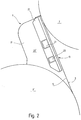
- Figure 1 shows a section of a dryer section of a paper manufacturing machine with an arrangement 1 for guiding a material web or paper web 3, which is guided together with a conveyor belt 5 from a first drying cylinder 7 via a web guide roller 9 to a second drying cylinder 11, in the area of the drying cylinder 7, 11 the material web rests on the cylinder surface and the conveyor belt 5 in the area of the web guide roller 9.
- a first free running path 13 is created between the first drying cylinder 7 and the web guide roller 9 and a second free running path 15 between the web guide roller 9 and the second drying cylinder 11.
- a web stabilizer 17 is provided between the running routes 13 and 15, which is designed, for example, as a suction box and can vacuum the area of the free running routes 13 and 15 and also the web guide roller 9.
- the web stabilizer 17 stabilizes the paper web 3 on the conveyor belt 5 in the region of the free running paths 13 and 15. If the web guide roller 9 is also vacuumed by the web stabilizer 17, the material web guided over the surface of the web guide roller 9 also becomes sucked on the conveyor belt 5 and thus stabilized.
- the web stabilizer can also be designed as a transfer foil or air guide box, which is used to transfer the paper web from the first drying cylinder 7 to the web guide roller 9 and / or from the web guide roller 9 to the subsequent drying cylinder 11 and to transfer the paper web with negative and / or positive pressure or blowing air can be acted upon.
- an air guiding device 19 in the form of a scraper is provided, which removes the air entrained by the conveyor belt 5 so that it does not enter the area of the web stabilizer 7 arrives.
- the web stabilizer 17 extends essentially over the entire width of the paper web 3.
- a separate blow box 21 is preferably provided on both sides in the region of the edge of the paper web 3.
- the blow box 21 shown in Figure 1 is attached to the side wall 23 of the web stabilizer 17.
- the blow box 21 is mounted so that it can be aligned and adjusted independently of the web stabilizer 17.
- the blow box 21 shown in this embodiment is the opening nip 25 assigned between the surface of the drying cylinder 7 and the running paper web 3. It is provided with a supply air connection Z and has at least one blowing nozzle which opens in the direction of the conveyor belt 5 and which is explained in more detail with reference to FIG. 4.
- the blow box 21 is supplied with air by means of the supply air connection Z, which is sucked off by the web stabilizer 17, for example in the form of a suction box, and / or delivered by a separate compressed air supply device, for example a compressor.
- a separate compressed air supply device for example a compressor.
- An exemplary embodiment of the arrangement is preferred in which the blow box 21 is supplied exclusively with the air drawn off by the web stabilizer 17, which simplifies the construction of the drying section and ensures reliable transfer of the paper web 5, even at high production speeds.
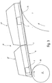
- FIG. 2 shows a modified embodiment of an arrangement 1 for guiding a material web or paper web 3.
- the cylinders around which the paper web 3 is guided together with a conveyor belt 5 have the same diameter here. They can both be designed as drying cylinders 7 and 7 '.
- the free running path 13 between the two drying cylinders 7 and 7 ' is here also assigned a web stabilizer 17, which, however, does not act on the free running path which runs from the drying cylinder 7'.
- a blow box 21 is attached to its side wall 23 'and is arranged in the region of the edge of the paper web 3. Unlike the one shown in FIG. 1, the blow box 21 here has two supply air connections Z 1 and Z 2.
- the two blow boxes shown in FIGS. 1 and 2 have in common that they are arranged on the side of the conveyor belt 5 and through this stabilize the paper web 3 on the conveyor belt 5.
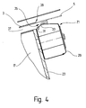
- FIG. 3 again shows a section of a machine for producing a material web or a paper production machine, within which a paper web 3 is guided over two rollers.
- the paper web 3 can be guided by a deflecting roller 27 onto a drying cylinder 7, the diameter of which is substantially larger than that of the deflecting roller 27.
- the deflecting roller 27 can serve as a web guide roller. It is also conceivable to heat them.
- the free running path 13 interacts with a blow box 21, which here is of multi-part design and has a first partial blow box 21 'and a second partial blow box 21' '. It is also conceivable to use several small web stabilizers to guide the paper web in the area of the free running path 13.
- Each of the blow boxes 21 'and 21'' has a supply air connection Z.
- the blow box 21 is also arranged in the region of the edge of the paper web 3.
- the blow box shown in Figure 3 is characterized by the fact that it extends over the entire length of the free running path 13 and can thus act both on the running nip 26 and on the running nip 25, in which the material web on the surface of the drying cylinder 7 accumulates. The air entrained by the drying cylinder 7 and the material web creates an overpressure in the nip 25.
- one of the partial blow boxes 21 'and 21' ' can be dispensed with, so that only the running nip 26 or the running nip 25 is subjected to stabilization or guidance of the material web.
- FIG. 4 finally shows a cross section through a blow box 21.
- this has a housing 29 which is suitably connected to an air supply device, so that an overpressure prevails within the housing 29.
- the air exits through an outlet slot 31 that opens near a curved housing portion 33.
- the outlet slot 31 is designed such that the air flows along the curved housing section 33 and exits from a gap 35 located between the housing 29 and the conveyor belt 5.
- the air is directed in such a way that a negative pressure builds up in the space 37 between web stabilizer 17 and conveyor belt 5, or the pressure still present by web stabilizer 17 is increased.
- the blow box 21 is in the region of the edge 39 of the material web or paper web 3 arranged and thus causes in particular a safe guidance of the web edge, so that fluttering and thus the risk of a web break can be practically avoided entirely.
- the conveyor belt 5 is shown in two positions: the rest position of the conveyor belt 5 is shown with solid lines, its working position with dashed lines.
- FIG. 4 clearly shows that the blow box 21, which is attached to a side wall 23 of the web stabilizer 17, can be adjusted and adjusted independently of the latter relative to the conveyor belt 5 and the paper web 3.
- the arrangement of the outlet slot 31 can also be chosen so that the outflowing air optimally abuts the curved housing section 33 and reliably delimits the intermediate space 37 from the environment outside the paper-making machine in such a way that a negative pressure is built up there.
- blow boxes are preferably attached to both sides of the web stabilizer, as shown in the figures. Since the blow boxes are formed separately from the web stabilizer, the blow boxes can be aligned independently of this with respect to the conveyor belt 5 or the paper web 3, so that reliable vacuum generation on the sides the paper web 3 is guaranteed. If the blow box is formed in several parts or several small blow boxes are arranged one behind the other in the area of a free running path, these can be adjusted independently of one another and thus optimally adapted to the course of the conveyor belt 5 and paper web 3.
- blow boxes interact with practically arbitrarily designed web stabilizers and can therefore be used universally.
Abstract
Description
Die Erfindung betrifft eine Anordnung zum Führen einer Materialbahn, insbesondere einer Faserstoffbahn, gemäß Oberbegriff des Anspruchs 1.The invention relates to an arrangement for guiding a material web, in particular a fibrous web, according to the preamble of
Vorrichtungen der hier angesprochenen Art sind bekannt (DE 35 04 820 A1). Sie dienen dazu, die Materialbahn innerhalb einer Maschine zur Herstellung der Materialbahn so zu führen, daß auch bei hohen Maschinengeschwindigkeiten ein Bahnflattern beziehungsweise -abriß sicher vermieden wird. Es hat sich herausgestellt, daß nicht in allen Fällen eine optimale Abdichtung der Anordnung zum Führen der Materialbahn gewährleistet werden kann.Devices of the type mentioned here are known (
Es ist daher Aufgabe der Erfindung, eine Anordnung der eingangs genannten Art zu schaffen, die diese Nachteile nicht aufweist.It is therefore an object of the invention to provide an arrangement of the type mentioned at the outset which does not have these disadvantages.
Zur Lösung dieser Aufgabe wird eine Anordnung zum Führen einer Materialbahn vorgeschlagen, die die in Anspruch 1 genannten Merkmale aufweist. Dadurch, daß die Anordnung zum Führen einer Materialbahn mindestens einen Blaskasten aufweist, der im Bereich des seitlichen Bahnrandes an den Seiten des Bahnstabilisators angebracht ist, kann eine optimale Abdichtung dadurch erfolgen, daß der Blaskasten unabhängig vom Bahnstabilisator exakt ausgerichtet und an den Verlauf der Materialbahn angepaßt werden kann. Insbesondere kann der Blaskasten -unabhängig vom Bahnstabilisator- entsprechend der Auslenkung des die Materialbahn durch die Herstellungsmaschine führenden Transportbandes angeordnet werden, um eine optimale Abdichtung gegenüber der Umgebung zu gewährleisten. Auf diese Weise wird sichergestellt, daß die Bahnränder auf dem Transportband so fixiert werden, daß ein Flattern praktisch auszuschließen ist, was insbesondere bei hohen Geschwindigkeiten wesentlich ist.To solve this problem, an arrangement for guiding a material web is proposed, which has the features mentioned in
Besonders bevorzugt wird eine Ausführungsform der Anordnung, die sich dadurch auszeichnet, daß wenigstens ein Blaskasten mehrteilig ausgebildet ist. Die einzelnen Elemente des Blaskastens können damit unabhängig voneinander angeordnet beziehungsweise justiert werden, um eine optimale Abdichtung gegenüber der Umgebung zu gewährleisten.An embodiment of the arrangement is particularly preferred, which is characterized in that at least one blow box is constructed in several parts. The individual elements of the blow box can thus be arranged or adjusted independently of one another in order to ensure an optimal seal from the surroundings.
Weitere Ausgestaltungen ergeben sich aus den übrigen Unteransprüchen.Further configurations result from the remaining subclaims.
Die Erfindung wird im folgenden anhand der Zeichnung näher erläutert. Es zeigen:
Figuren 1 bis 3- drei Ausführungsbeispiele einer Anordnung zum Führen einer Materialbahn und
- Figur 4
- einen Querschnitt durch eine in den
Figuren 1 bis 3 dargestellte Anordnung.
- Figures 1 to 3
- three embodiments of an arrangement for guiding a material web and
- Figure 4
- a cross section through an arrangement shown in Figures 1 to 3.
Die im folgenden beschriebene Anordnung zum Führen einer Materialbahn kann allgemein eingesetzt werden. Sie wird anhand einer Papierherstellungsmaschine erläutert, die eine Trockenpartie aufweist, in der die Material- beziehungsweise Papierbahn gemeinsam mit einem auch als Trockenfilz oder -sieb bezeichneten Transportband mäanderförmig um Trockenzylinder und Bahnleitwalzen geführt wird.The arrangement described below for guiding a material web can be used in general. It is explained on the basis of a paper production machine which has a dryer section, in which the material or paper web is guided in a meandering manner around the drying cylinder and web guide rollers together with a conveyor belt also referred to as a dry felt or wire.
Figur 1 zeigt einen Ausschnitt aus einer Trockenpartie einer Papierherstellungsmaschine mit einer Anordnung 1 zum Führen einer Materialbahn beziehungsweise Papierbahn 3, die gemeinsam mit einem Transportband 5 von einem ersten Trockenzylinder 7 über eine Bahnleitwalze 9 zu einem zweiten Trockenzylinder 11 geführt wird, wobei im Bereich der Trockenzylinder 7, 11 die Materialbahn auf der Zylinderoberfläche aufliegt und im Bereich der Bahnleitwalze 9 das Transportband 5. Zwischen dem ersten Trockenzylinder 7 und der Bahnleitwalze 9 entsteht eine erste freie Laufstrecke 13 und zwischen der Bahnleitwalze 9 und dem zweiten Trockenzylinder 11 eine zweite freie Laufstrecke 15. Zwischen den Laufstrecken 13 und 15 ist ein Bahnstabilisator 17 vorgesehen, der beispielsweise als Saugkasten ausgebildet ist und der den Bereich der freien Laufstrecke 13 und 15 sowie auch die Bahnleitwalze 9 besaugen kann. Durch den Bahnstabilisator 17 wird die Papierbahn 3 auf dem Transportband 5 im Bereich der freien Laufstrecken 13 und 15 stabilisiert. Wenn auch die Bahnleitwalze 9 von dem Bahnstabilisator 17 besaugt wird, wird auch die über die Oberfläche der Bahnleitwalze 9 geführte Materialbahn auf dem Transportband 5 angesaugt und damit stabilisiert. Der Bahnstabilisator kann auch als Transferfoil beziehungsweise Luftleitkasten ausgebildet sein, der dem Überführen der Papierbahn vom ersten Trockenzylinder 7 auf die Bahnleitwalze 9 und/oder von der Bahnleitwalze 9 auf den nachfolgenden Tockenzylinder 11 dient und der zum Überführen der Papierbahn mit Unter- und/oder Überdruck beziehungsweise Blasluft beaufschlagbar ist.Figure 1 shows a section of a dryer section of a paper manufacturing machine with an
Bei dem hier dargestellten Ausführungsbeispiel wird davon ausgegangen, daß sich der erste Trockenzylinder 7 gegen den Uhrzeigersinn und der zweite Trockenzylinder 11 im Uhrzeigersinn bewegt. Entsprechend ist nahe dem Ablaufpunkt A, in dem das Transportband 5 und die Papierbahn 3 von der Oberfläche des Trockenzylinder 11 abheben, eine Luftleiteinrichtung 19 in Form eines Schabers vorgesehen, die die von dem Transportband 5 mitgerissene Luft abträgt, so daß diese nicht in den Bereich des Bahnstabilisators 7 gelangt.In the exemplary embodiment shown here, it is assumed that the first drying
Der Bahnstabilisator 17 erstreckt sich im wesentlichen über die gesamte Breite der Papierbahn 3. Vorzugsweise an beiden im Bereich des Randes der Papierbahn 3 gelegenen Seiten ist ein separater Blaskasten 21 vorgesehen. Der in Figur 1 dargestellte Blaskasten 21 ist an der Seitenwand 23 des Bahnstabilisators 17 befestigt. Der Blaskasten 21 ist so angebracht, daß er unabhängig von dem Bahnstabilisator 17 ausgerichtet und justiert werden kann. Der in diesem Ausführungsbeispiel dargestellte Blaskasten 21 ist dem sich öffenden Nip 25 zwischen der Oberfläche des Trockenzylinders 7 und der ablaufenden Papierbahn 3 zugeordnet. Er ist mit einem Zuluftanschluß Z versehen und weist mindestens eine sich in Richtung zum Transportband 5 öffnende Blasdüse auf, die anhand von Figur 4 näher erläutert wird. Der Blaskasten 21 wird mittels des Zuluftanschlusses Z mit Luft versorgt, die von dem, beispielsweise als Saugkasten ausgebildeten Bahnstabilisator 17 abgesaugt und/oder von einer separaten Druckluft-Versorgungseinrichtung beispielsweise einem Kompressor, angeliefert wird. Es wird ein Ausführungsbeispiel der Anordnung bevorzugt, bei dem der Blaskasten 21 ausschließlich mit der von dem Bahnstabilisator 17 abgesaugten Luft versorgt wird, wodurch der Aufbau der Trockenpartie vereinfacht und ein sicheres überführen der Papierbahn 5 -auch bei hohen Herstellungsgeschwindigkeiten- gewährleistet ist.The
Figur 2 zeigt eine abgewandelte Ausführung einer Anordnung 1 zum Führen einer Materialbahn beziehungsweise Papierbahn 3. Die Zylinder, um die die Papierbahn 3 gemeinsam mit einem Transportband 5 geführt wird, haben hier den gleichen Durchmesser. Sie können beide als Trockenzylinder 7 und 7' ausgebildet sein. Der freien Laufstrecke 13 zwischen den beiden Trockenzylindern 7 und 7' ist auch hier ein Bahnstabilisator 17 zugeordnet, der allerdings nicht auf die freie Laufstrecke einwirkt, die von dem Trockenzylinder 7' abläuft.FIG. 2 shows a modified embodiment of an
Der Bahnstabilisator 17 erstreckt sich, wie der in Figur 1 erläuterte, über die gesamte Breite der Papierherstellungsmaschine. An seiner Seitenwand 23' ist ein Blaskasten 21 angebracht, der im Bereich des Randes der Papierbahn 3 angeordnet ist. Der Blaskasten 21 weist hier, anders als der in Figur 1 gezeigte, zwei Zuluftanschlüsse Z 1 und Z 2 auf.The
Den beiden in den Figuren 1 und 2 dargestellten Blaskästen ist gemeinsam, daß sie auf der Seite des Transportbandes 5 angeordnet sind und durch dieses hindurch die Papierbahn 3 auf dem Transportband 5 stabilisieren.The two blow boxes shown in FIGS. 1 and 2 have in common that they are arranged on the side of the
Figur 3 zeigt wiederum einen Ausschnitt aus einer Maschine zur Herstellung einer Materialbahn beziehungsweise einer Papierherstellungsmaschine, innerhalb derer eine Papierbahn 3 über zwei Walzen geführt wird. Beispielsweise kann die Papierbahn 3 von einer Umlenkwalze 27 auf einen Trockenzylinder 7 geführt werden, dessen Durchmesser wesentlich größer ist als der der Umlenkwalze 27. Die Umlenkwalze 27 kann als Bahnleitwalze dienen. Denkbar ist es auch, diese zu beheizen. Wesentlich ist, daß die freie Laufstrecke 13 mit einem Blaskasten 21 zusammenwirkt, der hier mehrteilig ausgebildet ist und einen ersten Teilblaskasten 21' sowie einen zweiten Teilblaskasten 21'' aufweist. Denkbar ist es auch, mehrere kleine Bahnstabilisatoren einzusetzen, um die Papierbahn im Bereich der freien Laufstrecke 13 zu führen.FIG. 3 again shows a section of a machine for producing a material web or a paper production machine, within which a
Jeder der Teilblaskästen 21' und 21'' weist einen Zuluftanschluß Z auf. Der Blaskasten 21 ist auch hier im Bereich des Randes der Papierbahn 3 angeordnet. Der in Figur 3 dargestellte Blaskasten zeichnet sich dadurch aus, daß er sich über die gesamte Länge der freien Laufstrecke 13 erstreckt und damit sowohl auf den ablaufenden Nip 26 als auch auf den auflaufenden Nip 25 wirken kann, in dem die Materialbahn auf die Oberfläche des Trockenzylinders 7 aufläuft. Durch die von dem Trockenzylinder 7 und der Materialbahn mitgerissenen Luft besteht ein Überdruck im Nip 25.Each of the blow boxes 21 'and 21''has a supply air connection Z. The
Je nach Flatterverhalten der Papierbahn 3 kann auf einen der Teilblaskästen 21' und 21'' verzichtet werden, so daß nur der ablaufende Nip 26 oder der auflaufende Nip 25 einer Stabilisierung beziehungsweise Führung der Materialbahn unterworfen wird.Depending on the flutter behavior of the
Figur 4 zeigt schließlich einen Querschnitt durch einen Blaskasten 21. Es ist ersichtlich, daß dieser ein Gehäuse 29 aufweist, das auf geeignete Weise mit einer Luftversorgungseinrichtung verbunden ist, so daß innerhalb des Gehäuses 29 ein Überdruck vorherrscht ist. Die Luft tritt durch einen Auslaßschlitz 31 aus, der sich nahe eines gekrümmten Gehäuseabschnitts 33 öffnet. Der Auslaßschlitz 31 ist so ausgebildet, daß die Luft an dem gekrümmten Gehäuseabschnitt 33 entlangströmt und aus einem zwischen Gehäuse 29 und Transportband 5 liegenden Spalt 35 austritt. Die Luft wird dabei derart gelenkt, daß in dem Zwischenraum 37 zwischen Bahnstabilisator 17 und Transportband 5 ein Unterdruck aufgebaut beziehungsweise der durch den Bahnstabilisator 17 noch vorhandene verstärkt wird. Der Blaskasten 21 ist im Bereich des Randes 39 der Materialbahn beziehungsweise Papierbahn 3 angeordnet und bewirkt damit insbesondere eine sichere Führung des Bahnrandes, so daß ein Flattern und damit die Gefahr eines Bahnabrisses praktisch gänzlich vermieden werden kann.Figure 4 finally shows a cross section through a
In Figur 4 ist das Transportband 5 in zwei Positionen dargestellt: Mit durchgezogenen Linien ist die Ruhestellung des Transportbandes 5 gezeigt, mit gestrichelten Linien dessen Arbeitsposition.In Figure 4, the
Besonders Figur 4 läßt deutlich erkennen, daß der Blaskasten 21, der an einer Seitenwand 23 des Bahnstabllisators 17 angebracht ist, unabhängig von diesem gegenüber dem Transportband 5 und der Papierbahn 3 justiert und eingestellt werden kann. Auch die Anordnung des Auslaßschlitzes 31 kann so gewählt werden, daß die ausströmende Luft optimal an dem gekrümmten Gehäuseabschnitt 33 anliegt und den Zwischenraum 37 sicher gegenüber der außerhalb der Papierherstellungsmaschine liegenden Umgebung derart abgrenzt, daß dort einen Unterdruck aufbaut wird.In particular, FIG. 4 clearly shows that the
Aus der Beschreibung zu den Figuren 1 bis 4 wird deutlich, daß vorzugsweise an beiden Seiten des Bahnstabilisators 17 Blaskästen angebracht werden, wie sie in den Figuren dargestellt sind. Da die Blaskästen separat gegenüber dem Bahnstabilisator ausgebildet sind, können die Blaskästen unabhängig von diesem gegenüber dem Transportband 5 beziehungsweise der Papierbahn 3 ausgerichtet werden, so daß eine sichere Unterdruckerzeugung an den Seiten der Papierbahn 3 gewährleistet ist. Wenn der Blaskasten mehrteilig ausgebildet wird oder mehrere kleine Blaskästen hintereinander im Bereich einer freien Laufstrecke angeordnet werden, können diese unabhängig voneinander justiert und damit optimal an den Verlauf von Transportband 5 und Papierbahn 3 angepaßt werden.From the description of Figures 1 to 4 it is clear that 17 blow boxes are preferably attached to both sides of the web stabilizer, as shown in the figures. Since the blow boxes are formed separately from the web stabilizer, the blow boxes can be aligned independently of this with respect to the
Aus dem oben Gesagten wird schließlich auch deutlich, daß die Blaskästen mit praktisch beliebig ausgestalteten Bahnstabilisatoren zusammenwirken und damit universell eingesetzt werden können.From what has been said above, it finally becomes clear that the blow boxes interact with practically arbitrarily designed web stabilizers and can therefore be used universally.
Claims (5)
Applications Claiming Priority (2)
| Application Number | Priority Date | Filing Date | Title |
|---|---|---|---|
| DE19601989 | 1996-01-20 | ||
| DE19601989A DE19601989C2 (en) | 1996-01-20 | 1996-01-20 | Arrangement for guiding a material web |
Publications (3)
| Publication Number | Publication Date |
|---|---|
| EP0785306A2 true EP0785306A2 (en) | 1997-07-23 |
| EP0785306A3 EP0785306A3 (en) | 1998-09-09 |
| EP0785306B1 EP0785306B1 (en) | 2002-05-02 |
Family
ID=7783253
Family Applications (1)
| Application Number | Title | Priority Date | Filing Date |
|---|---|---|---|
| EP96117463A Expired - Lifetime EP0785306B1 (en) | 1996-01-20 | 1996-10-31 | Apparatus for guiding web material |
Country Status (5)
| Country | Link |
|---|---|
| US (1) | US5893505A (en) |
| EP (1) | EP0785306B1 (en) |
| CN (1) | CN1158816A (en) |
| CA (1) | CA2195142A1 (en) |
| DE (2) | DE19601989C2 (en) |
Cited By (1)
| Publication number | Priority date | Publication date | Assignee | Title |
|---|---|---|---|---|
| DE102017123189A1 (en) | 2017-10-06 | 2019-04-11 | Voith Patent Gmbh | Web guiding device for stabilizing a laminar material web, drying section of a web guiding device and method for operating a web guiding device for stabilizing a laminar material web in a drying section |
Families Citing this family (9)
| Publication number | Priority date | Publication date | Assignee | Title |
|---|---|---|---|---|
| CH693304A5 (en) * | 1997-08-01 | 2003-05-30 | Roland Man Druckmasch | Turning bar and turning bar arrangement for a rotary printing press. |
| US6325896B1 (en) * | 1999-09-23 | 2001-12-04 | Valmet-Karlstad Ab | Apparatus for transferring a fast running fibrous web from a first location to a second location |
| EP1605098A1 (en) * | 2000-02-26 | 2005-12-14 | Voith Paper Patent GmbH | Vacuum belt conveyor |
| US6513263B2 (en) * | 2000-10-06 | 2003-02-04 | Enerquin Air Inc. | Ventilator for offset pocket and method of ventilating the same |
| DE102005057426A1 (en) * | 2005-11-30 | 2007-05-31 | Andritz Küsters GmbH & Co. KG | Compact reduced pressure conveyor belt device for guiding moving sheet, e.g. in paper or cardboard production machine, has long gap ejector(s) for applying reduced pressure to endless belt to fix sheet |
| US8042807B2 (en) * | 2006-12-21 | 2011-10-25 | Palo Alto Research Center Incorporated | Transport for printing systems |
| DE102009056625B9 (en) | 2009-12-02 | 2011-05-12 | Paprima Industries Inc., Dorval | Extension device for an air guide box |
| DE102010056576B8 (en) | 2010-12-30 | 2015-05-07 | Paprima Industries Inc. | Papermaking machine and method of making paper |
| DE102015001008A1 (en) * | 2015-01-28 | 2016-07-28 | Andritz Küsters Gmbh | Process and apparatus for the production of wetlaid nonwovens |
Citations (1)
| Publication number | Priority date | Publication date | Assignee | Title |
|---|---|---|---|---|
| DE3504820A1 (en) | 1984-03-02 | 1985-09-12 | Valmet Oy, Helsinki | DEVICE IN THE DRYING SECTION OF A PAPER MACHINE |
Family Cites Families (8)
| Publication number | Priority date | Publication date | Assignee | Title |
|---|---|---|---|---|
| FI76142C (en) * | 1985-11-14 | 1988-09-09 | Valmet Oy | FICKVENTILATIONSFOERFARANDE OCH -ANORDNING I EN PAPPERSMASKINS MAONGCYLINDERTORK. |
| US4669198A (en) * | 1986-04-08 | 1987-06-02 | Beloit Corp. | Blow box for a dryer |
| US4698919A (en) * | 1986-04-08 | 1987-10-13 | Beloit Corp. | Apparatus for assisting the transfer of a web to a drying section |
| US5507104A (en) * | 1987-02-13 | 1996-04-16 | Beloit Technologies, Inc. | Web drying apparatus |
| DE3706541A1 (en) * | 1987-02-28 | 1988-09-08 | Voith Gmbh J M | DEVICE FOR STABILIZING THE RUN OF A GOODS, IN PARTICULAR FOR STABILIZING A PAPER, IN THE DRYING PART OF A PAPER MACHINE |
| DE3739338C2 (en) * | 1987-11-20 | 1995-09-07 | Voith Gmbh J M | Air guide box for stabilizing the running of a web, in particular a paper web |
| FI82502C (en) * | 1989-05-02 | 1991-03-11 | Valmet Paper Machinery Inc | Method and apparatus in the drying section of a paper machine to effect the tip drawing of the web |
| FI95732C (en) * | 1992-01-13 | 1996-03-11 | Valmet Paperikoneet Oy | Device in the dryer section of a paper machine |
-
1996
- 1996-01-20 DE DE19601989A patent/DE19601989C2/en not_active Expired - Fee Related
- 1996-10-31 EP EP96117463A patent/EP0785306B1/en not_active Expired - Lifetime
- 1996-10-31 DE DE59609152T patent/DE59609152D1/en not_active Expired - Lifetime
- 1996-12-20 CN CN96121583A patent/CN1158816A/en active Pending
-
1997
- 1997-01-15 CA CA002195142A patent/CA2195142A1/en not_active Abandoned
- 1997-01-17 US US08/786,104 patent/US5893505A/en not_active Expired - Lifetime
Patent Citations (1)
| Publication number | Priority date | Publication date | Assignee | Title |
|---|---|---|---|---|
| DE3504820A1 (en) | 1984-03-02 | 1985-09-12 | Valmet Oy, Helsinki | DEVICE IN THE DRYING SECTION OF A PAPER MACHINE |
Cited By (1)
| Publication number | Priority date | Publication date | Assignee | Title |
|---|---|---|---|---|
| DE102017123189A1 (en) | 2017-10-06 | 2019-04-11 | Voith Patent Gmbh | Web guiding device for stabilizing a laminar material web, drying section of a web guiding device and method for operating a web guiding device for stabilizing a laminar material web in a drying section |
Also Published As
| Publication number | Publication date |
|---|---|
| DE59609152D1 (en) | 2002-06-06 |
| DE19601989C2 (en) | 2002-01-31 |
| EP0785306A3 (en) | 1998-09-09 |
| DE19601989A1 (en) | 1997-07-24 |
| US5893505A (en) | 1999-04-13 |
| CA2195142A1 (en) | 1997-07-21 |
| EP0785306B1 (en) | 2002-05-02 |
| CN1158816A (en) | 1997-09-10 |
Similar Documents
| Publication | Publication Date | Title |
|---|---|---|
| AT392991B (en) | DRYING PART FOR A MACHINE FOR THE PRODUCTION OR PROCESSING OF FIBER STRIPS, ESPECIALLY PAPER STRIPS | |
| EP0639668B1 (en) | Drying section | |
| AT403385B (en) | TWO-SCREEN CYLINDER DRYERS | |
| EP0427015A2 (en) | Device for suspended transport web or sheet materials | |
| WO1985000841A1 (en) | Paper machine | |
| CH637089A5 (en) | BLOW BOX FOR FLOATING GUIDING AND / OR PROMOTING RAILWAYS OR ARCHES. | |
| CH676459A5 (en) | ||
| DE4112355A1 (en) | PRESS RELEASE OF A PAPER MACHINE | |
| DE3706541A1 (en) | DEVICE FOR STABILIZING THE RUN OF A GOODS, IN PARTICULAR FOR STABILIZING A PAPER, IN THE DRYING PART OF A PAPER MACHINE | |
| DE3818600C2 (en) | ||
| DE19601989C2 (en) | Arrangement for guiding a material web | |
| DE3630570A1 (en) | METHOD AND DEVICE IN A PAPER MACHINE CYLINDER DRYER USING TWO-SCREEN GUIDE | |
| DE69923078T2 (en) | DRY LOT | |
| DE3344217A1 (en) | DEVICE FOR TRANSFERRING A PAPER RAIL FROM THE PRESS TO THE DRYING SECTION OF A PAPER MACHINE | |
| DE29924658U1 (en) | Device for conveying and guiding an infeed strip of a web in a paper machine | |
| EP2217759B1 (en) | Device for transferring a paper web from a supporting fabric to another | |
| DE3836751A1 (en) | AIR GUIDE BOX FOR STABILIZING THE RUN OF A RAILWAY, e.g. PAPER RAIL | |
| DE4311351C2 (en) | Dryer section | |
| DD239816A5 (en) | DEVICE FOR DRYING MATERIAL RAILS, IN PARTICULAR PAPER WEBS | |
| AT400856B (en) | DEVICE FOR CONVERTING A FIBER web | |
| DE3716468C2 (en) | ||
| DE4201107C2 (en) | Dryer section | |
| DE19548307A1 (en) | Drying section of paper or paper board machine | |
| DE102006049151A1 (en) | Vacuum belt conveyor for web forming machine, has vacuum unit creating vacuum effect on belt loop for conveying threading tail, and dividing structure arranged with turning roll in travel direction of tail for creating axial vacuum zones | |
| AT410684B (en) | THREADING DEVICE AND METHOD FOR THREADING THE END OF A TRAIN |
Legal Events
| Date | Code | Title | Description |
|---|---|---|---|
| PUAI | Public reference made under article 153(3) epc to a published international application that has entered the european phase |
Free format text: ORIGINAL CODE: 0009012 |
|
| AK | Designated contracting states |
Kind code of ref document: A2 Designated state(s): DE FI SE |
|
| PUAL | Search report despatched |
Free format text: ORIGINAL CODE: 0009013 |
|
| AK | Designated contracting states |
Kind code of ref document: A3 Designated state(s): DE FI SE |
|
| RAP1 | Party data changed (applicant data changed or rights of an application transferred) |
Owner name: VOITH SULZER PAPIERTECHNIK PATENT GMBH |
|
| 17P | Request for examination filed |
Effective date: 19990309 |
|
| 17Q | First examination report despatched |
Effective date: 20000720 |
|
| RAP1 | Party data changed (applicant data changed or rights of an application transferred) |
Owner name: VOITH PAPER PATENT GMBH |
|
| GRAG | Despatch of communication of intention to grant |
Free format text: ORIGINAL CODE: EPIDOS AGRA |
|
| GRAG | Despatch of communication of intention to grant |
Free format text: ORIGINAL CODE: EPIDOS AGRA |
|
| GRAH | Despatch of communication of intention to grant a patent |
Free format text: ORIGINAL CODE: EPIDOS IGRA |
|
| GRAH | Despatch of communication of intention to grant a patent |
Free format text: ORIGINAL CODE: EPIDOS IGRA |
|
| GRAA | (expected) grant |
Free format text: ORIGINAL CODE: 0009210 |
|
| AK | Designated contracting states |
Kind code of ref document: B1 Designated state(s): DE FI SE |
|
| REF | Corresponds to: |
Ref document number: 59609152 Country of ref document: DE Date of ref document: 20020606 |
|
| PLBI | Opposition filed |
Free format text: ORIGINAL CODE: 0009260 |
|
| PLBQ | Unpublished change to opponent data |
Free format text: ORIGINAL CODE: EPIDOS OPPO |
|
| PLBF | Reply of patent proprietor to notice(s) of opposition |
Free format text: ORIGINAL CODE: EPIDOS OBSO |
|
| 26 | Opposition filed |
Opponent name: METSO PAPER INC. AIR SYSTEMS Effective date: 20030131 |
|
| PLBB | Reply of patent proprietor to notice(s) of opposition received |
Free format text: ORIGINAL CODE: EPIDOSNOBS3 |
|
| PLCK | Communication despatched that opposition was rejected |
Free format text: ORIGINAL CODE: EPIDOSNREJ1 |
|
| APAH | Appeal reference modified |
Free format text: ORIGINAL CODE: EPIDOSCREFNO |
|
| APBP | Date of receipt of notice of appeal recorded |
Free format text: ORIGINAL CODE: EPIDOSNNOA2O |
|
| PLAB | Opposition data, opponent's data or that of the opponent's representative modified |
Free format text: ORIGINAL CODE: 0009299OPPO |
|
| R26 | Opposition filed (corrected) |
Opponent name: METSO PAPER INC. AIR SYSTEMS Effective date: 20030131 |
|
| RAP2 | Party data changed (patent owner data changed or rights of a patent transferred) |
Owner name: VOITH PATENT GMBH |
|
| APBU | Appeal procedure closed |
Free format text: ORIGINAL CODE: EPIDOSNNOA9O |
|
| PLBN | Opposition rejected |
Free format text: ORIGINAL CODE: 0009273 |
|
| STAA | Information on the status of an ep patent application or granted ep patent |
Free format text: STATUS: OPPOSITION REJECTED |
|
| 27O | Opposition rejected |
Effective date: 20061205 |
|
| PGFP | Annual fee paid to national office [announced via postgrant information from national office to epo] |
Ref country code: SE Payment date: 20101014 Year of fee payment: 15 |
|
| REG | Reference to a national code |
Ref country code: SE Ref legal event code: EUG |
|
| PG25 | Lapsed in a contracting state [announced via postgrant information from national office to epo] |
Ref country code: SE Free format text: LAPSE BECAUSE OF NON-PAYMENT OF DUE FEES Effective date: 20111101 |
|
| PGFP | Annual fee paid to national office [announced via postgrant information from national office to epo] |
Ref country code: DE Payment date: 20121023 Year of fee payment: 17 Ref country code: FI Payment date: 20121011 Year of fee payment: 17 |
|
| REG | Reference to a national code |
Ref country code: DE Ref legal event code: R119 Ref document number: 59609152 Country of ref document: DE Effective date: 20140501 |
|
| PG25 | Lapsed in a contracting state [announced via postgrant information from national office to epo] |
Ref country code: DE Free format text: LAPSE BECAUSE OF NON-PAYMENT OF DUE FEES Effective date: 20140501 Ref country code: FI Free format text: LAPSE BECAUSE OF NON-PAYMENT OF DUE FEES Effective date: 20131031 |