EP0786624A2 - Small once-through boiler - Google Patents
Small once-through boiler Download PDFInfo
- Publication number
- EP0786624A2 EP0786624A2 EP97300450A EP97300450A EP0786624A2 EP 0786624 A2 EP0786624 A2 EP 0786624A2 EP 97300450 A EP97300450 A EP 97300450A EP 97300450 A EP97300450 A EP 97300450A EP 0786624 A2 EP0786624 A2 EP 0786624A2
- Authority
- EP
- European Patent Office
- Prior art keywords
- combustion
- regenerator
- chamber
- combustion chamber
- boiler
- Prior art date
- Legal status (The legal status is an assumption and is not a legal conclusion. Google has not performed a legal analysis and makes no representation as to the accuracy of the status listed.)
- Withdrawn
Links
Images


Classifications
-
- F—MECHANICAL ENGINEERING; LIGHTING; HEATING; WEAPONS; BLASTING
- F23—COMBUSTION APPARATUS; COMBUSTION PROCESSES
- F23L—SUPPLYING AIR OR NON-COMBUSTIBLE LIQUIDS OR GASES TO COMBUSTION APPARATUS IN GENERAL ; VALVES OR DAMPERS SPECIALLY ADAPTED FOR CONTROLLING AIR SUPPLY OR DRAUGHT IN COMBUSTION APPARATUS; INDUCING DRAUGHT IN COMBUSTION APPARATUS; TOPS FOR CHIMNEYS OR VENTILATING SHAFTS; TERMINALS FOR FLUES
- F23L15/00—Heating of air supplied for combustion
- F23L15/02—Arrangements of regenerators
-
- F—MECHANICAL ENGINEERING; LIGHTING; HEATING; WEAPONS; BLASTING
- F24—HEATING; RANGES; VENTILATING
- F24H—FLUID HEATERS, e.g. WATER OR AIR HEATERS, HAVING HEAT-GENERATING MEANS, e.g. HEAT PUMPS, IN GENERAL
- F24H7/00—Storage heaters, i.e. heaters in which the energy is stored as heat in masses for subsequent release
-
- F—MECHANICAL ENGINEERING; LIGHTING; HEATING; WEAPONS; BLASTING
- F22—STEAM GENERATION
- F22B—METHODS OF STEAM GENERATION; STEAM BOILERS
- F22B21/00—Water-tube boilers of vertical or steeply-inclined type, i.e. the water-tube sets being arranged vertically or substantially vertically
- F22B21/02—Water-tube boilers of vertical or steeply-inclined type, i.e. the water-tube sets being arranged vertically or substantially vertically built-up from substantially straight water tubes
- F22B21/04—Water-tube boilers of vertical or steeply-inclined type, i.e. the water-tube sets being arranged vertically or substantially vertically built-up from substantially straight water tubes involving a single upper drum and a single lower drum, e.g. the drums being arranged transversely
- F22B21/06—Water-tube boilers of vertical or steeply-inclined type, i.e. the water-tube sets being arranged vertically or substantially vertically built-up from substantially straight water tubes involving a single upper drum and a single lower drum, e.g. the drums being arranged transversely the water tubes being arranged annularly in sets, e.g. in abutting connection with drums of annular shape
- F22B21/065—Water-tube boilers of vertical or steeply-inclined type, i.e. the water-tube sets being arranged vertically or substantially vertically built-up from substantially straight water tubes involving a single upper drum and a single lower drum, e.g. the drums being arranged transversely the water tubes being arranged annularly in sets, e.g. in abutting connection with drums of annular shape involving an upper and lower drum of annular shape
-
- F—MECHANICAL ENGINEERING; LIGHTING; HEATING; WEAPONS; BLASTING
- F22—STEAM GENERATION
- F22B—METHODS OF STEAM GENERATION; STEAM BOILERS
- F22B31/00—Modifications of boiler construction, or of tube systems, dependent on installation of combustion apparatus; Arrangements of dispositions of combustion apparatus
- F22B31/08—Installation of heat-exchange apparatus or of means in boilers for heating air supplied for combustion
-
- Y—GENERAL TAGGING OF NEW TECHNOLOGICAL DEVELOPMENTS; GENERAL TAGGING OF CROSS-SECTIONAL TECHNOLOGIES SPANNING OVER SEVERAL SECTIONS OF THE IPC; TECHNICAL SUBJECTS COVERED BY FORMER USPC CROSS-REFERENCE ART COLLECTIONS [XRACs] AND DIGESTS
- Y02—TECHNOLOGIES OR APPLICATIONS FOR MITIGATION OR ADAPTATION AGAINST CLIMATE CHANGE
- Y02E—REDUCTION OF GREENHOUSE GAS [GHG] EMISSIONS, RELATED TO ENERGY GENERATION, TRANSMISSION OR DISTRIBUTION
- Y02E20/00—Combustion technologies with mitigation potential
- Y02E20/34—Indirect CO2mitigation, i.e. by acting on non CO2directly related matters of the process, e.g. pre-heating or heat recovery
Definitions
- the present invention relates to a small once-through boiler. More particularly, the present invention relates to improvement of a combustion chamber of a small once-through boiler.
- a combustion chamber of a prior art small once-through boiler configures a heating surface by doubly and annularly arranging water pipes 103 and 104 inside a furnace wall (inner peripheral wall) 102 of an elongated cylindrical furnace body 101 and aims to cool down the furnace wall 102.
- the water pipes 103 provided on the outer side are connected with each other by fins 109 and embedded halfway in the furnace wall 102 or, although not shown, they are tightly connected with each other without fins so as to be embedded halfway or to come into contact with the furnace wall 102.
- the water pipes 104 provided on the inner side are disposed so as to form between the water pipes 104 and the water pipes 103 a space along which exhaust gas flows.
- Annular arrangement of the inner water pipes 104 and the outer water pipes 103 which are connected with each other by means of the fins 109 or tightly connected with each other constitutes the space between the inner water pipes 104 and the outer water pipes 103 as a passage 105 along which exhaust gas flows.
- the inner surface of the water pipes 104 facing a combustion chamber 110 serves as a radiant heat transfer surface
- the inner surface of the water pipes 103 facing the passage 105 and the outer surface of the water pipe 104 function as a convective heat transfer surface.
- communicating openings 106 at which the passage 105 communicates with the combustion chamber 110 are provided between the adjacent water pipes 104 disposed in the vicinity of a bottom of the combustion chamber, and exhaust openings 108 at which an exhaust means 107 communicates with the passage 105 are provided between the adjacent water pipes 103 disposed in the vicinity of a top of the combustion chamber, whereby combustion gas generated in the combustion chamber 110 is lead from the communicating openings 106 provided at the bottom of the combustion chamber to the passage 105 between the inner water pipes 104 and the outer water pipes 103 to be exhausted from the exhaust openings 108 provided at the top of the boiler.
- the large convective heat transfer portion is therefore provided together with the radiant heat transfer portion in the conventional boiler so that heat of the combustion gas can be sufficiently recovered in the convective heat transfer portion.
- a temperature of the combustion gas obtained by lighting a fire in the burner 111 at the top of the boiler is lowered to approximately 1200 °C at the bottom of the boiler by radiant heat transfer in the combustion chamber 110, and it is further lowered to approximately 300 °C when passing through the convective heat transfer portion between the inner water pipe group 104 and the outer water pipe group 103, thereafter being exhausted.
- a temperature of the combustion gas becomes maximum in the vicinity of a fire hole of the burner 111, which may cause such a problem as that the heat load of the combustion chamber can not be increased. That is, in case of a once-through boiler, water is heated when passing through the water pipes upward to become vapor, a water/hot water area 112, a boiling area 113 and a vapor area 114 where water is dried out are thus formed upward in the mentioned order in the water pipes 103 and 104.
- the vapor area 114 is therefore disadvantageously positioned in the vicinity of the fire hole of the burner 111. Water or vapor, however, has a small coefficient of heat transfer.
- the small once-through boiler is characterized in that: at least one regenerative burner system is provided in a combustion chamber, the regenerative burner system performing supply of combustion air and exhaust of combustion gas through a regenerator and supplying combustion air through the regenerator heated by heat of combustion gas by relatively changing flows of combustion gas and combustion air with respect to the regenerator; a water pipe group is provided apart from a wall surface of the combustion chamber to form a passage between a rear surface of the water pipe group and the wall surface of the combustion chamber; and communicating openings through which combustion gas passes are formed between adjacent water pipes at each of upper and lower ends of the water pipe group so that a part of combustion gas passes along the passage on the rear side of the water group, whereby the part of the combustion gas flows from the lower communicating openings into the passage upward and again flows from the upper communicating openings into the combustion chamber.
- the inner surface of the water pipes facing the combustion chamber is therefore heated by radiant heat of the combustion gas injected into the combustion chamber.
- a part of the combustion gas is then turned around to ascend at the bottom of the furnace and directly exhausted through the regenerator of the regenerative burner system.
- the remaining combustion gas flows from the communicating openings provided at the bottom of the combustion chamber into the passage at the rear side of the water pipes and again flows from the upper communicating openings into the combustion chamber.
- a part of the combustion gas is accompanied with the combustion air to be recycled, and the remaining part of the same is exhausted through the regenerator of the regenerative burner system.
- a part of the combustion gas again flowing from the upper communicating openings into the combustion chamber through the passage between the water pipe group and the furnace wall of the combustion chamber is accompanied with the combustion air injected into the combustion chamber to increase a capacity of the combustion gas.
- Increase in capacity of the combustion gas prevents the flame from rising and ensures that the combustion gas reaches the bottom of the combustion chamber to enable heating at the bottom of the combustion chamber by radiant heat transfer even though the combustion chamber has a large depth.
- recycle of the combustion gas also achieves reduction in Nox.
- increase in quantity of the combustion gas circulating between the combustion chamber and the passage at the rear of the water pipes decreases a difference in temperatures between an inlet side and an outlet side of the passages provided at the rear of the water pipes, which can increase the quantity of heat transferred to the water pipes and reduce the heat transfer surface area when obtaining the same quantity of vapor.
- the flame and the combustion gas around the fire hole of the burner are diluted with gas, which has been used for radiant heat transfer and the convective heat transfer to reduce its temperature, to lower the temperature, and hence the temperature of the combustion gas in the combustion chamber is evenly increased without generating an area locally having a high temperature.
- Increase in the heat load quantity in the combustion chamber therefore ensures reduction in size of the boiler.
- sensible heat produced when the high-temperature combustion exhaust gas passes through the regenerator to be exhausted is recovered to the regenerator by direct heat exchange.
- Heat recovered to the regenerator is used to preheat the combustion air by direct heat exchange with extremely-high efficiency and is returned to the combustion chamber.
- the temperature of the combustion air is heightened to be close to that of the combustion gas flowing to the regenerator, and hence use of the high-temperature combustion air can maintain combustion with less fuel and rapidly increase the temperature in the combustion chamber.
- the combustion exhaust gas is exhausted at a lower temperature (approximately 200°C or below) than that obtained in the conventional boiler. According to the small once-through boiler of the present invention, heat balance is therefore excellent and a necessary quantity of vapor can be generated with less fuel, thus greatly reducing the running cost as compared with the prior art.
- a regenerative burner system by which fuel is continuously injected from the same fuel nozzle without interruption and flows of the combustion exhaust gas and the combustion air are relatively changed with respect to the regenerator.
- combustion can not be interrupted because regenerative combustion is achieved by only changing flows of the combustion exhaust gas and the combustion air without interruption. Pressure fluctuation or irregularity of temperature distribution in the combustion chamber can be thus reduced.
- the combustion air and the fuel which are separately injected into the combustion chamber directly are mixed together after being injected into the combustion chamber, the combustion air has an extremely-high temperature (approximately 1000°C or more), thereby producing stable combustion.
- the regenerative burner system comprises a regenerator which is uniformly partitioned into three or more chambers in the circumferential direction in such a manner that fluid can pass through each chamber along the axial direction, a fuel nozzle which pierces the center of the regenerator and directly injects the fuel in the combustion chambers, an outlet/inlet means having an air supply chamber connected with a combustion air supply system and an exhaust chamber connected with a combustion gas exhaust system, and a changing means which is provided between the outlet/inlet means and the regenerator to separate the regenerator from the outlet/inlet means and continuously or intermittently rotates to ensure the exhaust chamber and the air supply chamber of the outlet/inlet means to sequentially communicate with any compartment of the regenerator divided into three or more chambers without allowing overlap, the fuel being continuously injected into the combustion chamber and the high-temperature combustion air being directly injected around the fuel from the regenerator into the combustion chamber with an injection portion being moved in the circumferential direction.
- the air supply chamber and the exhaust chamber of the outlet/inlet means are intermittently or continuously communicated with different chambers/compartments of the regenerator through the changing means which continuously rotates so that the combustion air and the combustion exhaust gas simultaneously flows in the regenerator without being mixed together.
- the combustion air and the combustion exhaust gas therefore flow in the same chamber/compartment at different points in time, for example, the combustion air flows in the regenerator after the combustion exhaust gas has left the regenerator, the combustion air is preheated to a high temperature close to that of the combustion exhaust gas to be supplied by using heat of the regenerator which was heated when the combustion exhaust gas passed therethrough.
- the regenerative burner system which alternately burns a pair of burners, each of which has a regenerator, in a short time so that exhaust is made through the regenerator of a burner which is not making combustion.
- frequent changes in position of the flame further uniforms the temperature distribution in the combustion chamber, reducing irregularity of heating. This reduces fluctuation of heat load of the furnace and makes the state of boiler water in the water pipes uniform, which suppresses local generation of only vapor that may damage the water pipes.
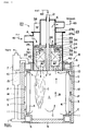
- Figs. 1 to 5 show an embodiment of a small once-through boiler according to the present invention.
- the small once-through boiler has a group of water pipes 4 annularly provided inside an elongated cylindrical furnace body 2 forming, for example, a combustion chamber 1 separately from an inner peripheral wall surface 3 of the furnace body 2.
- the annularly-provided group of water pipes 4 forms the combustion chamber 1 inside thereof.
- the group of water pipes 4 are connected with each other by means of a lower header 5 and an upper header 6.
- the upper header 6 and the lower header 5 are connected with each other through a vapor-liquid separator 7.
- Boiler water 15 supplied from the lower header 5 is heated when moving upward inside the water pipes 4 and boiled to be turned into vapor.
- a cylindrical passage 12 is formed between the inner peripheral wall surface 3 of the furnace body 2 and the annular pipe wall constituted by a plurality of water pipes 4.
- Upper communicating openings 10 and lower communicating openings 11 are provided in the vicinity of the upper and lower ends of the water pipes 4, i.e., a furnace top portion 8 and a furnace bottom portion 9 to ensure incoming and outgoing of the combustion gas by achieving communication of the passage 12 with the combustion chamber 1 provided inside of the group of water pipes 4.
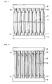
- the upper and lower communicating openings 10 and 11 can be obtained by narrowing each aperture of the water pipes 4 at the upper and lower ends thereof to form a gap between two adjacent water pipes.
- the group of water pipes 4 are closely, arranged with no gap therebetween except for the both end portions thereof, and a passage 12 which communicates with the combustion chamber 1 through the upper and lower communicating openings 10 and 11 between the water pipes and the combustion chamber wall surface 3 is formed to provide a pipe wall surrounding the combustion chamber 1.
- the communicating openings 10 and 11 may be formed by fixing fins 13 to portions other than upper and lower ends of the water pipes 4 and connecting fins 13 of adjacent water pipes 4 with each other by welding or riveting.
- the water pipes 4 are connected with each other at portions other than the upper and lower communicating openings 10 and 11 by means of the headers 5 and 6 at both ends so as not to produce a gap therebetween, but this structure does not aim to completely eliminates the gap and there is no problem if a small gap is generated to cause leakage.
- the furnace body 2 is usually formed by lining the inside of the steel casing with a fire resisting insulation or providing an air-cooled layer for flowing cooling air therethrough inside the casing. Further, the water pipes 4 may be so arranged as to form a duplex tube depending on the situation. In such a case, fins 13 annularly provided on the outer side may be welded to reach the upper and lower headers 5 and 6 with no clearance so that the combustion gas can circulate between the two tubes without leaking outside, and the water pipe group forming the outer annular tube may function as a furnace wall, which eliminates necessity of the fire resisting insulation material.
- a regenerative burner system 20 is provided to the furnace top portion 8 of this furnace body 2 as a heat source. Although one regenerative burner system 20 is provided to the combustion chamber 1 in this embodiment, two or more burner systems may be provided depending on the situation.
- a fuel nozzle 21 for injecting fuel F directly into the combustion chamber 1 pierces the center of the regenerator 22 so that high-temperature combustion air A is injected from the circumference of the jet of the fuel F in substantially parallel with the fuel jet.
- the system which aims to supply the combustion air A and emit the exhaust gas E is basically constituted by: the regenerator 22 that is uniformly partitioned into three or more chambers, e.g., three chambers designated by reference numerals 30, 31 and 32 in the circumferential direction in this embodiment to ensure the fluid to pass therethrough in the axial direction; an outlet/inlet portion 23 having an air supply chamber 23a connected with an air supply system 41 and an exhaust chamber 23b connected with an exhaust system 43; and a changing means 24 which is provided between the outlet/inlet means 23 and the regenerator 22 to separate the regenerator 22 from the outlet/inlet means 23, has an air supply communicating hole 25 and an exhaust communicating hole 26 that do not simultaneously exist in the same compartment and continuously or intermittently rotates to achieve sequential communication of the exhaust chamber 23b and the air supply chamber 23a of the outlet/inlet means 23 with any of the chambers 30, 31 and 32 of the regenerator 22.
- the regenerator 22 is not restricted to a certain shape or material, it is preferable to use a honey-comb-shaped regenerator produced by extrusion-molding ceramics such as cordierite or mullite for heat exchange between the exhaust gas having a temperature of approximately 100°C and the combustion air having a temperature of approximately 20°C.
- a honey-comb-shaped regenerator produced by extrusion-molding ceramics such as cordierite or mullite for heat exchange between the exhaust gas having a temperature of approximately 100°C and the combustion air having a temperature of approximately 20°C.
- cylindrical regenerators which have a plurality of honey-comb-shaped cell holes, molded with material having a relatively-lower pressure loss but a large calorific capacity and high durability such as ceramics.
- the regenerators are not restricted to this type, and any other type of regenerator such as a ceramic ball or a nugget may be used.
- the honey-comb-shaped regenerator 22 may be manufactured using material other than ceramics, e.g., metal such as heat resisting steel depending on the situation.
- metal such as aluminum, iron or copper that is relatively cheaper than ceramics for the intermediate or high temperature of approximately 500 to 600°C.
- honey-comb shape essentially means hexagon cells (holes) but a plurality of square or triangular cells, as well as hexagon cells, are also included in this specification.
- honey-comb-shaped regenerator 22 may be obtained by not only integral molding as described above but also bundling tubes.
- the regenerator 22 is divided into three chambers in the circumferential direction by distribution chambers 27 provided in front of and at the rear of the regenerator 22.
- the inside of the regenerator 22 is partitioned into three chambers, i.e., a vacant chamber 30 in which no fluid flows, a chamber 31 in which the exhaust gas E flows and a chamber 32 in which the air A flows by the distribution chambers 27 each of which is divided into three chambers 29a, 29b and 29c by means of partitions 28 in this embodiment.
- the regenerator 22 itself has a honey-comb shape consisting of a set of cells constituting independent passages, and a set of cells within a range partitioned by the partitions 28 of the distribution chamber 27 thus forms one partitioned chamber. Provision of the distribution chamber 27 can disperse the fluid which flows in or out through the communicating holes 25 and 26 to be uniformly split over the entire regenerator 22.
- the shape of the regenerator 22 is not restricted to the illustrated honey-comb shape, and flat-plate type or corrugated-plate type regenerative material may be radially provided inside the cylindrical casing or pipe-type regenerative material may be filled in the cylindrical casing so as to pass the fluid in the axial direction, although not shown.
- the single regenerator 22 is substantially divided into three chambers 30, 31 and 32 by the distribution chamber 27 in this embodiment, but the present invention is not limited to this structure and the regenerator 22 itself may be previously partitioned into three chambers.
- a cylindrical casing which is divided into three chambers in the circumferential direction by partition walls so as to enable the fluid to pass therethrough in the axial direction may be prepared, and a lump of spherical-type, short-pipe-type, short-rod-type, strip-type, nugget-type or net-type regenerative material can be filled in each of these chambers.
- regenerative material such as Si 3 N 4 that can be used at a higher temperature than that suitable for cordierite or mullite is used for the regenerator 22, it is hard to mold the regenerator 22 into the complicated honey-comb shape, but it can be readily molded into a simple pipe-like a rod-like or a ball-like shape.
- a chamber 32 in which the air A flows (referred to as an air supply chamber hereinbelow) and a chamber 31 in which the exhaust gas E flows (referred to as an exhaust chamber hereinbelow) form a pair
- the combination of this pair and at least one vacant chamber 30 corresponds to a number of chambers partitioned in the regenerator 22, and three is determined to a minimum number.
- formation of the chamber 30 in which no fluid flows between the air supply chamber 32 and the exhaust chamber 31 can constitute the above-mentioned system. In this case, a minimum number of chambers is four.
- the outlet/inlet means 23 is partitioned into an air supply chamber 23a connected with the air supply system 41 and an exhaust chamber 23b connected with the exhaust system 43 by providing the cylindrical partition wall 34 in the rectangular casing 33.
- the air supply chamber 23a is formed outside the partition wall 34 and the exhaust chamber 23b is formed inside the same in this embodiment.
- the changing means 24 is so disposed as to independently rotate between the outlet/inlet means 23 and the distribution chamber 27 in this embodiment. Between the partition wall 34 and the changing means 24 is provided a sealing member 35 so as to allow rotation of the changing means 24 and to prevent the fluid from leaking.
- the changing means 24 is rotatably supported by, e.g., the partition wall 34 of the outlet/inlet means 23 and the central fuel nozzle 21 and has a gear 36 formed on the peripheral edge thereof so that the gear 36 engages with a drive gear 37 positioned at a corner of the casing 33 to be rotated and driven by a motor 38.
- rotation and driving may be enabled by a friction wheel, a chain or a belt pressure-welded on the peripheral edge of the changing means 24.
- the changing means 24 that achieves communication of the air supply chamber 23a and the exhaust chamber 23b of the outlet/inlet means 23 only with the corresponding chambers/compartments 32 and 31 of the regenerator 22 is a disc orthogonal to the passage, and is provided with at least one air supply communicating hole 25 that ensures any one compartment of the regenerator 22 to communicate with the air supply chamber 23a and at least one exhaust communicating hole 26 that ensures any one compartment to communicate with the exhaust chamber 23b.
- the exhaust communicating hole 26 and the air supply communicating hole 25 are formed to satisfy the following three conditions: (1) The air supply communicating hole 25 and the exhaust communicating hole 26 do not simultaneously exist in the same chamber/compartment; (2) starting from the foremost communicating hole positioned in a chamber/compartment following the vacant chamber 30, the communicating holes sequentially change its position to the subsequent chamber/compartment one by one; and (3) the size of the air supply communicating hole 25 and the exhaust communicating hole 26 is such that these holes can be simultaneously accommodated in one chamber when they are arranged so as not to overlap one on another.
- the air supply communicating hole 25 and the exhaust communicating hole 26 are set to be holes having substantially the same size and shape, the present invention is not restricted to this configuration, and the air supply communicating hole 25 and the exhaust communicating hole 26 may have different dimensions or shapes, or the size or shape may differ depending on each communicating hole if necessary. In general, these holes may be so set as to substantially balance a quantity of air and a quantity of exhaust gas, but one communicating hole may be set larger than the other hole depending on the situation.
- the fuel nozzle 21 is disposed so that it is directly exposed or protrudes toward the combustion chamber 1 through the regenerator 22.
- the regenerator 22 is enclosed by a casing 39 made of heat resisting material and accommodated in a metal casing 33. Also, the fuel nozzle 21 is held in a heat resistant casing 39.
- the heat resistant casing 39 are formed three injection openings 40, that communicate with the respective chambers 29a, 29b and 29c of the distribution chamber 27, in the axial direction.
- the entire peripheral surface of the water pipes functions as a heat transfer surface in the following manner to realize uniform heating without irregularity.
- the air A and the fuel F supplied into the combustion chamber 1 through the air supply system 41 and the fuel supply system 42 are mixed together to be burnt.
- the combustion air A is preheated to have a high temperature by passing through the regenerator 22 of the regenerative burner system 20 heated by start-up combustion and thereafter supplied into the combustion chamber 1. Further, the fuel F is directly injected from the fuel nozzle 21 into the combustion chamber 1.
- the high-temperature air A and the fuel F injected from the fuel nozzle 21 are separately injected into the combustion chamber 1, spread in the combustion chamber 1 and mixed together apart from the fuel nozzle 21.
- the air A and the fuel F widely spread in the mixing area to make mixture difficult, which is essentially a condition unsuitable for combustion.
- the air A itself has, however, a high temperature of 700 to 800°C or above, and hence combustion is readily enabled under such a condition. That is, the air A preheated to have a high temperature of 700 to 800°C or above is injected into the combustion chamber 1 and, at the same time, involves the combustion exhaust gas.
- the concentration of oxygen is therefore lower than that of the usual air immediately before combustion.
- combustion starts the moment oxygen contacts with the fuel and is stably maintained even though the concentration of oxygen is extremely lower than that of the usual combustion air because of the combustion air preheated to have a high temperature above a self ignition temperature of the fuel or a combustion stabilizing temperature of the mixture. Further, if the concentration of oxygen immediately before combustion is greatly lower than usual as a result of involvement of furnace exhaust gas, an oxidative exothermic reaction rate becomes lower, thereby obtaining the flame forming a flat temperature distribution having a large volume with no peak.
- the combustion stabilizing temperature of the mixture in a given concentration of oxygen may differ depending on its concentration of oxygen or a type of fuel but it is usually lower than a temperature of the above-described combustion air (700 to 800°C ) in the regularly-used fuel.
- the high-temperature preheated air supplied through the regenerator 22 therefore has a temperature equal to or above the combustion stabilizing limit temperature.
- the inner surface of the water pipes 4 facing the combustion chamber 1 is heated by radiant heat of the combustion gas C generated from this combustion.
- a part of the combustion gas C thereafter flows from the lower communicating openings 11 at the furnace bottom portion 9 into the passage 12 at the rear of the water pipes 4 to rise (indicated by an arrow P), and heats the rear surface of the water pipes 4 by convective heat transfer before returning from the upper communicating openings 10 to the combustion chamber 1. Furthermore, the remaining combustion gas C turns around at the furnace bottom portion 9 to move upward (arrow B) in the combustion chamber 1 and is exhausted outside the furnace from the injection opening 40 of the chamber 31 of the regenerator connected with the exhaust system 43.
- a part of the combustion gas which has flown into the passage 12 through the lower communicating openings 11 again flows from the upper communicating openings 10 into the combustion chamber 1 through the passage 12, a part thereof being accompanied with the air A injected from the injection opening 40 to be recycled while the remaining part of the same being mixed with the combustion gas that has turned around and moved upward in the combustion chamber 1 to be exhausted through the regenerator 22.
- the combustion gas C again flowing from the upper communicating openings 10 into the combustion chamber 1 through the passage 12 has a temperature lowered by convective heat transfer when passing through the passage 12 at the rear of water pipes 4.
- the combustion gas whose temperature has been decreased to approximately 1000°C at the combustion chamber bottom portion, again lowers its temperature when passing through the passage 12, the temperature further dropping to approximately 200°C when the combustion gas again flows from the upper communicating openings 10 into the combustion chamber 1.
- the combustion gas in the vicinity of the fire hole of the burner is diluted with the low-temperature combustion gas to decrease the temperature thereof, thereby entirely lowering the combustion gas temperature without generating an area locally having a high temperature.
- a part of the combustion gas again flowing into the combustion chamber 1 is accompanied with the combustion gas C injected from the burner system 20 to increase a capacity of the combustion gas C, and rising of the flame can be avoided while leading the combustion gas C to the bottom of the combustion chamber 1 even though the combustion chamber 1 has a large depth, thus uniformly heating the combustion chamber 1 in the vertical direction.
- reduction in Nox is also achieved by recycle of the combustion gas C.
- increase in a quantity of the combustion gas circulated in the combustion chamber leads to increase in a quantity of the combustion gas C flowing through the passage 12 at the rear of the water pipes 4, and a difference in temperature between gas around the lower communicating openings 11 and that around the upper communicating openings 10 hence becomes small to increase a quantity of heat transferred to the water pipes 4 and the boiler water 15, reducing the heat transfer surface area.
- a part of the combustion gas C which has been circulated toward the top of the combustion chamber 1 through the passage 12 between the water pipes 4 and the combustion chamber wall surface 3 and has a temperature of approximately 200°C is mixed with a part of a large quantity of combustion gas C having a temperature of approximately 1000°C which has been turned upward at the bottom of the combustion chamber 1 and circulated in the furnace, the mixture being exhausted as the exhaust gas having a temperature of approximately 900°C.
- the mixture is exhausted from the injection opening 40 communicating with the regenerator compartment 31 connected with the combustion gas exhaust system 43.
- the combustion air and combustion gas to flow in the regenerator 32 are changed over at intervals of, for example, 10 to 90 seconds, and more preferably, 10 to 20 seconds, or they are changed over when a temperature of the exhaust gas E exhausted through the regenerator 22 has reached a predetermined value, for example, about 200°C.
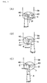
- the air A passing through the compartment/chamber 32 takes heat of the regenerator 22 to have a high temperature, i.e., a high temperature close to that of the exhaust gas that has heated the regenerator 22 and is directly injected from the circumference of the fuel nozzle 21 provided in the center of the regenerator 22 into the combustion chamber 1 in substantially parallel with the fuel F (the state shown in Fig. 5(A)).
- the exhaust gas E within the combustion chamber 1 is led by the function of an induced draft fan of the exhaust system 43 into the corresponding compartment 31 of the regenerator 22 communicating with the exhaust chamber 23b of the outlet/inlet means 23 through the exhaust communicating hole 26.
- the exhaust gas E whose temperature has been lowered by heating the corresponding compartment 31 of the regenerator 22 flows into the first chamber 29b of the distribution chamber 27 and is then exhausted to the exhaust chamber 23b through the exhaust communicating hole 26.
- continuous or intermittent clockwise rotation of the changing means 24 from the state shown in Fig. 2 involves the exhaust communicating hole 26 to reach the third chamber 29a of the distribution chamber provided on the left side thereof, ensuring that the first chamber 29b and the third chamber 29a simultaneously communicate with the exhaust chamber 23b.
- the exhaust gas E within the combustion chamber 1 flows in the first chamber 29b and the third chamber 29a of the distribution chamber 27 after passing through the two compartments 31 and 30 of the regenerator 22 and further flows into the exhaust chamber 23b connected with these chambers 29a and 29b through the exhaust communicating hole 26.
- the exhaust gas E is then exhausted.
- the exhaust communicating hole 26 has completely changed its position to the third chamber 29a (the vacant portion designated by reference numeral 30 in Fig.
- the air supply communicating hole 25 positioned in the second chamber 29c changes its position to the first chamber 29b (the chamber represented by reference numeral 31 in Fig. 2), and the area partitioned by the second chamber 29c (the chamber denoted by reference numeral 32 in Fig. 2) becomes vacant.
- the exhaust gas E flows into the vacant chamber 30 in which no fluid has flown
- the air A flows into the chamber 31 in which the exhaust gas E has flown
- no fluid flows into the chamber 32 in which the air A has flown.
- the regenerator 22 is therefore heated by heat of the exhaust gas E, and the air A passing through the heated regenerator 22 is heated by heat of the regenerator 22.
- a flow of the fluid is changed by utilizing the vacant chamber 30 while ensuring communication of the respective chambers 30 and 32 even though the air supply communicating hole 25 extends over both the vacant chamber 30 and the precedent chamber 32, and a flow of the fluid is not thus interrupted.
- the exhaust gas E is sequentially switched to the air A or vice versa without interrupting a flow.
- the combustion air A therefore passes through the heated regenerator 22 to become hot air having a high temperature close to that of the exhaust gas and is supplied to the combustion chamber 1 (the state shown in Fig. 5(B)).
- Continuous or intermittent rotation of the changing means 24 sequentially changes the position at which the air A is injected in the circumferential direction as shown in Figs. 5(A) to (C), and the flame rotates in the circumferential direction within the combustion chamber 1.
- the air supply system 41 and the exhaust system 43 are alternately changed over by the changing means 24 and connected with the fixed regenerator 22 in this embodiment, but the regenerator itself may be rotated between the exhaust system and the air supply system so as to relatively change flows of the exhaust gas and the air with respect to the regenerator.
- a flow of the fuel may be also changed besides the combustion air to alternately burn a pair of burners so that the combustion gas is exhausted through the regenerator of the burner that is being stopped.
- the air supply system and the exhaust system are connected to the regenerator/burner throat of the two burners through, e.g., a four-way valve so that each system is selectively connected to either the air supply system or the exhaust system.
- the air is supplied to one burner through the regenerator, while the combustion gas is exhausted from the other burner through the regenerator thereof.
- the fuel is alternately supplied to a pair of the burners by using, for example, a three-way valve.
- the temperature of the exhaust gas emitted via the regenerator 22 can be set to the minimum level, thereby enhancing the thermal efficiency of the entire boiler.
Abstract
Description
- The present invention relates to a small once-through boiler. More particularly, the present invention relates to improvement of a combustion chamber of a small once-through boiler.
- For example, as shown in Fig. 6, a combustion chamber of a prior art small once-through boiler configures a heating surface by doubly and annularly arranging
water pipes cylindrical furnace body 101 and aims to cool down thefurnace wall 102. Thewater pipes 103 provided on the outer side are connected with each other byfins 109 and embedded halfway in thefurnace wall 102 or, although not shown, they are tightly connected with each other without fins so as to be embedded halfway or to come into contact with thefurnace wall 102. Further, thewater pipes 104 provided on the inner side are disposed so as to form between thewater pipes 104 and the water pipes 103 a space along which exhaust gas flows. Annular arrangement of theinner water pipes 104 and theouter water pipes 103 which are connected with each other by means of thefins 109 or tightly connected with each other constitutes the space between theinner water pipes 104 and theouter water pipes 103 as apassage 105 along which exhaust gas flows. In the configuration of a combustion chamber in this boiler, the inner surface of thewater pipes 104 facing a combustion chamber 110 serves as a radiant heat transfer surface, and the inner surface of thewater pipes 103 facing thepassage 105 and the outer surface of thewater pipe 104 function as a convective heat transfer surface. - In the conventional boiler of a general type, communicating
openings 106 at which thepassage 105 communicates with the combustion chamber 110 are provided between theadjacent water pipes 104 disposed in the vicinity of a bottom of the combustion chamber, andexhaust openings 108 at which an exhaust means 107 communicates with thepassage 105 are provided between theadjacent water pipes 103 disposed in the vicinity of a top of the combustion chamber, whereby combustion gas generated in the combustion chamber 110 is lead from the communicatingopenings 106 provided at the bottom of the combustion chamber to thepassage 105 between theinner water pipes 104 and theouter water pipes 103 to be exhausted from theexhaust openings 108 provided at the top of the boiler. In other words, when the combustion gas generated in the combustion chamber 110 by combustion of a burner 111 is being exhausted from the communicatingopenings 106 at the bottom of the combustion chamber through theinner water pipes 104 and theouter water pipes 103, heat exchange is performed between the boiler water and the combustion gas by the radiant heat transfer and the convective heat transfer in order to obtain vapor. Although a flame temperature and furnace heat load are high in the radiant heat transfer portion, heat of the combustion gas can not be sufficiently utilized only in this portion. The exhaust gas temperature is therefore extremely heightened and the influence of the heat on the circumferential environment becomes large, which deteriorates the heat economy of the boiler. The large convective heat transfer portion is therefore provided together with the radiant heat transfer portion in the conventional boiler so that heat of the combustion gas can be sufficiently recovered in the convective heat transfer portion. For example, a temperature of the combustion gas obtained by lighting a fire in the burner 111 at the top of the boiler is lowered to approximately 1200 °C at the bottom of the boiler by radiant heat transfer in the combustion chamber 110, and it is further lowered to approximately 300 °C when passing through the convective heat transfer portion between the innerwater pipe group 104 and the outerwater pipe group 103, thereafter being exhausted. - In the configuration of the prior art combustion chamber, however, a temperature of the combustion gas becomes maximum in the vicinity of a fire hole of the burner 111, which may cause such a problem as that the heat load of the combustion chamber can not be increased. That is, in case of a once-through boiler, water is heated when passing through the water pipes upward to become vapor, a water/
hot water area 112, aboiling area 113 and avapor area 114 where water is dried out are thus formed upward in the mentioned order in thewater pipes vapor area 114 is therefore disadvantageously positioned in the vicinity of the fire hole of the burner 111. Water or vapor, however, has a small coefficient of heat transfer. Thus, heat having a high temperature can not be accepted by water or vapor, and the water pipes may be excessively heated by the flame. Decrease in temperature of the combustion gas in the vicinity of the fire hole in the burner 111 is hence the only way to prevent the water pipes from being burnt, and heat load of the combustion chamber must be decreased and the necessary quantity of vapor must be assured by increasing the size of the boiler in the prior art. - It is therefore an object of the present invention to provide a small once-through boiler which can prevent water pipes from being burnt by excessive heating and prevent the water pipes from being burnt in the vicinity of a burner in particular, the small once-through boiler being capable of further increasing heat load of a combustion chamber to reduce the size thereof as compared with a prior art small once-through boiler.
- To this end, the small once-through boiler according to the present invention is characterized in that: at least one regenerative burner system is provided in a combustion chamber, the regenerative burner system performing supply of combustion air and exhaust of combustion gas through a regenerator and supplying combustion air through the regenerator heated by heat of combustion gas by relatively changing flows of combustion gas and combustion air with respect to the regenerator; a water pipe group is provided apart from a wall surface of the combustion chamber to form a passage between a rear surface of the water pipe group and the wall surface of the combustion chamber; and communicating openings through which combustion gas passes are formed between adjacent water pipes at each of upper and lower ends of the water pipe group so that a part of combustion gas passes along the passage on the rear side of the water group, whereby the part of the combustion gas flows from the lower communicating openings into the passage upward and again flows from the upper communicating openings into the combustion chamber.
- The inner surface of the water pipes facing the combustion chamber is therefore heated by radiant heat of the combustion gas injected into the combustion chamber. A part of the combustion gas is then turned around to ascend at the bottom of the furnace and directly exhausted through the regenerator of the regenerative burner system. Also, the remaining combustion gas flows from the communicating openings provided at the bottom of the combustion chamber into the passage at the rear side of the water pipes and again flows from the upper communicating openings into the combustion chamber. A part of the combustion gas is accompanied with the combustion air to be recycled, and the remaining part of the same is exhausted through the regenerator of the regenerative burner system. This ensures the boiler water flowing in the water pipes facing the combustion chamber to be heatedby the radiant heat transfer from the flame and the combustion gas on the inner heat transfer surface facing the combustion chamber and heated by mainly the convective heat transfer of the combustion gas flowing in the passage on the outer heat transfer surface facing the passage. Therefore, even though the size of the combustion chamber is unchanged as in the prior art, the boiler can be reduced in size and price when obtaining the same quantity of vapor and a quantity of vapor can be further increased in the boiler according to the present invention when the heat transfer area is unchanged, as compared with the prior art.
- Further, a part of the combustion gas again flowing from the upper communicating openings into the combustion chamber through the passage between the water pipe group and the furnace wall of the combustion chamber is accompanied with the combustion air injected into the combustion chamber to increase a capacity of the combustion gas. Increase in capacity of the combustion gas prevents the flame from rising and ensures that the combustion gas reaches the bottom of the combustion chamber to enable heating at the bottom of the combustion chamber by radiant heat transfer even though the combustion chamber has a large depth. At this time, recycle of the combustion gas also achieves reduction in Nox. Further, increase in quantity of the combustion gas circulating between the combustion chamber and the passage at the rear of the water pipes decreases a difference in temperatures between an inlet side and an outlet side of the passages provided at the rear of the water pipes, which can increase the quantity of heat transferred to the water pipes and reduce the heat transfer surface area when obtaining the same quantity of vapor. Moreover, the flame and the combustion gas around the fire hole of the burner are diluted with gas, which has been used for radiant heat transfer and the convective heat transfer to reduce its temperature, to lower the temperature, and hence the temperature of the combustion gas in the combustion chamber is evenly increased without generating an area locally having a high temperature. Increase in the heat load quantity in the combustion chamber therefore ensures reduction in size of the boiler.
- Additionally, according to the prevent invention, sensible heat produced when the high-temperature combustion exhaust gas passes through the regenerator to be exhausted is recovered to the regenerator by direct heat exchange. Heat recovered to the regenerator is used to preheat the combustion air by direct heat exchange with extremely-high efficiency and is returned to the combustion chamber. The temperature of the combustion air is heightened to be close to that of the combustion gas flowing to the regenerator, and hence use of the high-temperature combustion air can maintain combustion with less fuel and rapidly increase the temperature in the combustion chamber. Also, the combustion exhaust gas is exhausted at a lower temperature (approximately 200°C or below) than that obtained in the conventional boiler. According to the small once-through boiler of the present invention, heat balance is therefore excellent and a necessary quantity of vapor can be generated with less fuel, thus greatly reducing the running cost as compared with the prior art.
- Here, according to the small once-through boiler of the present invention, it is preferable to use a regenerative burner system by which fuel is continuously injected from the same fuel nozzle without interruption and flows of the combustion exhaust gas and the combustion air are relatively changed with respect to the regenerator. In this case, combustion can not be interrupted because regenerative combustion is achieved by only changing flows of the combustion exhaust gas and the combustion air without interruption. Pressure fluctuation or irregularity of temperature distribution in the combustion chamber can be thus reduced. Although the combustion air and the fuel which are separately injected into the combustion chamber directly are mixed together after being injected into the combustion chamber, the combustion air has an extremely-high temperature (approximately 1000°C or more), thereby producing stable combustion.
- Furthermore, it is preferable that the regenerative burner system comprises a regenerator which is uniformly partitioned into three or more chambers in the circumferential direction in such a manner that fluid can pass through each chamber along the axial direction, a fuel nozzle which pierces the center of the regenerator and directly injects the fuel in the combustion chambers, an outlet/inlet means having an air supply chamber connected with a combustion air supply system and an exhaust chamber connected with a combustion gas exhaust system, and a changing means which is provided between the outlet/inlet means and the regenerator to separate the regenerator from the outlet/inlet means and continuously or intermittently rotates to ensure the exhaust chamber and the air supply chamber of the outlet/inlet means to sequentially communicate with any compartment of the regenerator divided into three or more chambers without allowing overlap, the fuel being continuously injected into the combustion chamber and the high-temperature combustion air being directly injected around the fuel from the regenerator into the combustion chamber with an injection portion being moved in the circumferential direction.
- In such a case, the air supply chamber and the exhaust chamber of the outlet/inlet means are intermittently or continuously communicated with different chambers/compartments of the regenerator through the changing means which continuously rotates so that the combustion air and the combustion exhaust gas simultaneously flows in the regenerator without being mixed together. The combustion air and the combustion exhaust gas therefore flow in the same chamber/compartment at different points in time, for example, the combustion air flows in the regenerator after the combustion exhaust gas has left the regenerator, the combustion air is preheated to a high temperature close to that of the combustion exhaust gas to be supplied by using heat of the regenerator which was heated when the combustion exhaust gas passed therethrough. When heat of the regenerator is lowered, rotation of the changing means moves the position at which the combustion air is injected in the circumferential direction and the regenerator of the combustion air supply means that has exhausted the combustion gas is used to supply the combustion air. Thus, the flame formed by the combustion air supplied while rotatably changing its position around the fuel nozzle and the fuel injected in the center rotates in the combustion chamber in the circumferential direction to uniformly heat the combustion chamber. In addition, frequent changes in position of the flame can obtain the uniform temperature distribution in the combustion chamber, thus reducing irregularity of heating.
- According to the small once-through boiler of the present invention, it is preferable to use the regenerative burner system which alternately burns a pair of burners, each of which has a regenerator, in a short time so that exhaust is made through the regenerator of a burner which is not making combustion. In such a case, frequent changes in position of the flame further uniforms the temperature distribution in the combustion chamber, reducing irregularity of heating. This reduces fluctuation of heat load of the furnace and makes the state of boiler water in the water pipes uniform, which suppresses local generation of only vapor that may damage the water pipes.
-
- Fig. 1 is a vertical cross-sectional view showing an embodiment of a small once-through boiler according to the present invention, taken along the central line of the boiler;
- Fig. 2 is a principle view showing a changing means of a regenerative burner system used in the small once-through boiler illustrated in Fig. 1;
- Fig. 3 is a development showing an embodiment of water pipes of the small once-through boiler according to the present invention;
- Fig. 4 is a development showing another embodiment of the water pipes;
- Fig. 5 is explanatory views of operations (A) to (C) where the flame rotates in the circumferential direction in the regenerative burner system used in the embodiment illustrated in Fig. 1;
- Fig. 6 is a horizontal cross-sectional view showing a combustion chamber of a prior art boiler; and
- Fig. 7 is a vertical cross-sectional view showing the case where the regenerative burner system is applied to the combustion chamber of the prior art boiler.
- The configuration of the present invention will now be described in detail based on a preferred embodiment illustrated in the accompanying drawings.
- Figs. 1 to 5 show an embodiment of a small once-through boiler according to the present invention. The small once-through boiler has a group of
water pipes 4 annularly provided inside an elongatedcylindrical furnace body 2 forming, for example, a combustion chamber 1 separately from an innerperipheral wall surface 3 of thefurnace body 2. The annularly-provided group ofwater pipes 4 forms the combustion chamber 1 inside thereof. The group ofwater pipes 4 are connected with each other by means of alower header 5 and anupper header 6. Also, theupper header 6 and thelower header 5 are connected with each other through a vapor-liquid separator 7.Boiler water 15 supplied from thelower header 5 is heated when moving upward inside thewater pipes 4 and boiled to be turned into vapor. It is then collected in theupper header 6 and moved to the vapor-liquid separator 7 where only vapor is taken out and warm water is again supplied through areflux pipe 14 as theboiler water 15. Acylindrical passage 12 is formed between the innerperipheral wall surface 3 of thefurnace body 2 and the annular pipe wall constituted by a plurality ofwater pipes 4. Upper communicatingopenings 10 and lower communicatingopenings 11 are provided in the vicinity of the upper and lower ends of thewater pipes 4, i.e., afurnace top portion 8 and afurnace bottom portion 9 to ensure incoming and outgoing of the combustion gas by achieving communication of thepassage 12 with the combustion chamber 1 provided inside of the group ofwater pipes 4. As shown in, e.g., Fig. 3, the upper and lower communicatingopenings water pipes 4 at the upper and lower ends thereof to form a gap between two adjacent water pipes. The group ofwater pipes 4 are closely, arranged with no gap therebetween except for the both end portions thereof, and apassage 12 which communicates with the combustion chamber 1 through the upper and lower communicatingopenings chamber wall surface 3 is formed to provide a pipe wall surrounding the combustion chamber 1. Further, the communicatingopenings fins 13 to portions other than upper and lower ends of thewater pipes 4 and connectingfins 13 ofadjacent water pipes 4 with each other by welding or riveting. In either case, thewater pipes 4 are connected with each other at portions other than the upper and lower communicatingopenings headers - The
furnace body 2 is usually formed by lining the inside of the steel casing with a fire resisting insulation or providing an air-cooled layer for flowing cooling air therethrough inside the casing. Further, thewater pipes 4 may be so arranged as to form a duplex tube depending on the situation. In such a case,fins 13 annularly provided on the outer side may be welded to reach the upper andlower headers regenerative burner system 20 is provided to thefurnace top portion 8 of thisfurnace body 2 as a heat source. Although oneregenerative burner system 20 is provided to the combustion chamber 1 in this embodiment, two or more burner systems may be provided depending on the situation. - The description will be given as to the embodiment where the regenerative burner system constitutes one burner. In this
regenerative burner system 20, afuel nozzle 21 for injecting fuel F directly into the combustion chamber 1 pierces the center of theregenerator 22 so that high-temperature combustion air A is injected from the circumference of the jet of the fuel F in substantially parallel with the fuel jet. - Here, the system which aims to supply the combustion air A and emit the exhaust gas E is basically constituted by: the regenerator 22 that is uniformly partitioned into three or more chambers, e.g., three chambers designated by
reference numerals inlet portion 23 having anair supply chamber 23a connected with anair supply system 41 and anexhaust chamber 23b connected with an exhaust system 43; and a changing means 24 which is provided between the outlet/inlet means 23 and theregenerator 22 to separate the regenerator 22 from the outlet/inlet means 23, has an airsupply communicating hole 25 and anexhaust communicating hole 26 that do not simultaneously exist in the same compartment and continuously or intermittently rotates to achieve sequential communication of theexhaust chamber 23b and theair supply chamber 23a of the outlet/inlet means 23 with any of thechambers regenerator 22. - Although the
regenerator 22 is not restricted to a certain shape or material, it is preferable to use a honey-comb-shaped regenerator produced by extrusion-molding ceramics such as cordierite or mullite for heat exchange between the exhaust gas having a temperature of approximately 100°C and the combustion air having a temperature of approximately 20°C. For theregenerators 22, there are preferably used cylindrical regenerators, which have a plurality of honey-comb-shaped cell holes, molded with material having a relatively-lower pressure loss but a large calorific capacity and high durability such as ceramics. In this case, burning sulfur components or its chemically-changed substance is captured in ceramics even though the temperature of the exhaust gas E is lowered below a sulfuric acid dew point when recovering heat from the exhaust gas E, which can prevent ducts of the exhaust system provided at the downstream side from corroding at a low temperature. Of course, the regenerators are not restricted to this type, and any other type of regenerator such as a ceramic ball or a nugget may be used. The honey-comb-shapedregenerator 22 may be manufactured using material other than ceramics, e.g., metal such as heat resisting steel depending on the situation. In addition, it is preferable to use metal such as aluminum, iron or copper that is relatively cheaper than ceramics for the intermediate or high temperature of approximately 500 to 600°C. It is to be noted that the honey-comb shape essentially means hexagon cells (holes) but a plurality of square or triangular cells, as well as hexagon cells, are also included in this specification. In addition, the honey-comb-shapedregenerator 22 may be obtained by not only integral molding as described above but also bundling tubes. In this embodiment, theregenerator 22 is divided into three chambers in the circumferential direction bydistribution chambers 27 provided in front of and at the rear of theregenerator 22. For example, the inside of theregenerator 22 is partitioned into three chambers, i.e., avacant chamber 30 in which no fluid flows, achamber 31 in which the exhaust gas E flows and achamber 32 in which the air A flows by thedistribution chambers 27 each of which is divided into threechambers partitions 28 in this embodiment. That is, theregenerator 22 itself has a honey-comb shape consisting of a set of cells constituting independent passages, and a set of cells within a range partitioned by thepartitions 28 of thedistribution chamber 27 thus forms one partitioned chamber. Provision of thedistribution chamber 27 can disperse the fluid which flows in or out through the communicatingholes entire regenerator 22. Furthermore, the shape of theregenerator 22 is not restricted to the illustrated honey-comb shape, and flat-plate type or corrugated-plate type regenerative material may be radially provided inside the cylindrical casing or pipe-type regenerative material may be filled in the cylindrical casing so as to pass the fluid in the axial direction, although not shown. Moreover, thesingle regenerator 22 is substantially divided into threechambers distribution chamber 27 in this embodiment, but the present invention is not limited to this structure and theregenerator 22 itself may be previously partitioned into three chambers. For instance, although not shown, a cylindrical casing which is divided into three chambers in the circumferential direction by partition walls so as to enable the fluid to pass therethrough in the axial direction may be prepared, and a lump of spherical-type, short-pipe-type, short-rod-type, strip-type, nugget-type or net-type regenerative material can be filled in each of these chambers. If regenerative material such as Si3N4 that can be used at a higher temperature than that suitable for cordierite or mullite is used for theregenerator 22, it is hard to mold theregenerator 22 into the complicated honey-comb shape, but it can be readily molded into a simple pipe-like a rod-like or a ball-like shape. - Assuming that a
chamber 32 in which the air A flows (referred to as an air supply chamber hereinbelow) and achamber 31 in which the exhaust gas E flows (referred to as an exhaust chamber hereinbelow) form a pair, the combination of this pair and at least one vacant chamber 30 (chamber in which no fluid flows) corresponds to a number of chambers partitioned in theregenerator 22, and three is determined to a minimum number. Further, formation of thechamber 30 in which no fluid flows between theair supply chamber 32 and theexhaust chamber 31 can constitute the above-mentioned system. In this case, a minimum number of chambers is four. - In this embodiment, the outlet/inlet means 23 is partitioned into an
air supply chamber 23a connected with theair supply system 41 and anexhaust chamber 23b connected with the exhaust system 43 by providing thecylindrical partition wall 34 in therectangular casing 33. Theair supply chamber 23a is formed outside thepartition wall 34 and theexhaust chamber 23b is formed inside the same in this embodiment. The changing means 24 is so disposed as to independently rotate between the outlet/inlet means 23 and thedistribution chamber 27 in this embodiment. Between thepartition wall 34 and the changing means 24 is provided a sealingmember 35 so as to allow rotation of the changingmeans 24 and to prevent the fluid from leaking. It is to be noted that the changingmeans 24 is rotatably supported by, e.g., thepartition wall 34 of the outlet/inlet means 23 and thecentral fuel nozzle 21 and has agear 36 formed on the peripheral edge thereof so that thegear 36 engages with adrive gear 37 positioned at a corner of thecasing 33 to be rotated and driven by amotor 38. It is needless to say that the present invention is not limited to this structure, and rotation and driving may be enabled by a friction wheel, a chain or a belt pressure-welded on the peripheral edge of the changingmeans 24. - The changing means 24 that achieves communication of the
air supply chamber 23a and theexhaust chamber 23b of the outlet/inlet means 23 only with the corresponding chambers/compartments regenerator 22 is a disc orthogonal to the passage, and is provided with at least one airsupply communicating hole 25 that ensures any one compartment of theregenerator 22 to communicate with theair supply chamber 23a and at least oneexhaust communicating hole 26 that ensures any one compartment to communicate with theexhaust chamber 23b. Theexhaust communicating hole 26 and the airsupply communicating hole 25 are formed to satisfy the following three conditions: (1) The airsupply communicating hole 25 and theexhaust communicating hole 26 do not simultaneously exist in the same chamber/compartment; (2) starting from the foremost communicating hole positioned in a chamber/compartment following thevacant chamber 30, the communicating holes sequentially change its position to the subsequent chamber/compartment one by one; and (3) the size of the airsupply communicating hole 25 and theexhaust communicating hole 26 is such that these holes can be simultaneously accommodated in one chamber when they are arranged so as not to overlap one on another. Here, although the airsupply communicating hole 25 and theexhaust communicating hole 26 are set to be holes having substantially the same size and shape, the present invention is not restricted to this configuration, and the airsupply communicating hole 25 and theexhaust communicating hole 26 may have different dimensions or shapes, or the size or shape may differ depending on each communicating hole if necessary. In general, these holes may be so set as to substantially balance a quantity of air and a quantity of exhaust gas, but one communicating hole may be set larger than the other hole depending on the situation. - The
fuel nozzle 21 is disposed so that it is directly exposed or protrudes toward the combustion chamber 1 through theregenerator 22. Theregenerator 22 is enclosed by acasing 39 made of heat resisting material and accommodated in ametal casing 33. Also, thefuel nozzle 21 is held in a heatresistant casing 39. Here, to the heatresistant casing 39 are formed threeinjection openings 40, that communicate with therespective chambers distribution chamber 27, in the axial direction. - According to the boiler having the above arrangement, the entire peripheral surface of the water pipes functions as a heat transfer surface in the following manner to realize uniform heating without irregularity.
- The air A and the fuel F supplied into the combustion chamber 1 through the
air supply system 41 and thefuel supply system 42 are mixed together to be burnt. The combustion air A is preheated to have a high temperature by passing through theregenerator 22 of theregenerative burner system 20 heated by start-up combustion and thereafter supplied into the combustion chamber 1. Further, the fuel F is directly injected from thefuel nozzle 21 into the combustion chamber 1. - Here, the high-temperature air A and the fuel F injected from the
fuel nozzle 21 are separately injected into the combustion chamber 1, spread in the combustion chamber 1 and mixed together apart from thefuel nozzle 21. At this time, the air A and the fuel F widely spread in the mixing area to make mixture difficult, which is essentially a condition unsuitable for combustion. The air A itself has, however, a high temperature of 700 to 800°C or above, and hence combustion is readily enabled under such a condition. That is, the air A preheated to have a high temperature of 700 to 800°C or above is injected into the combustion chamber 1 and, at the same time, involves the combustion exhaust gas. The concentration of oxygen is therefore lower than that of the usual air immediately before combustion. However, combustion starts the moment oxygen contacts with the fuel and is stably maintained even though the concentration of oxygen is extremely lower than that of the usual combustion air because of the combustion air preheated to have a high temperature above a self ignition temperature of the fuel or a combustion stabilizing temperature of the mixture. Further, if the concentration of oxygen immediately before combustion is greatly lower than usual as a result of involvement of furnace exhaust gas, an oxidative exothermic reaction rate becomes lower, thereby obtaining the flame forming a flat temperature distribution having a large volume with no peak. It is to be noted that the combustion stabilizing temperature of the mixture in a given concentration of oxygen may differ depending on its concentration of oxygen or a type of fuel but it is usually lower than a temperature of the above-described combustion air (700 to 800°C ) in the regularly-used fuel. The high-temperature preheated air supplied through theregenerator 22 therefore has a temperature equal to or above the combustion stabilizing limit temperature. The inner surface of thewater pipes 4 facing the combustion chamber 1 is heated by radiant heat of the combustion gas C generated from this combustion. A part of the combustion gas C thereafter flows from the lower communicatingopenings 11 at thefurnace bottom portion 9 into thepassage 12 at the rear of thewater pipes 4 to rise (indicated by an arrow P), and heats the rear surface of thewater pipes 4 by convective heat transfer before returning from the upper communicatingopenings 10 to the combustion chamber 1. Furthermore, the remaining combustion gas C turns around at thefurnace bottom portion 9 to move upward (arrow B) in the combustion chamber 1 and is exhausted outside the furnace from the injection opening 40 of thechamber 31 of the regenerator connected with the exhaust system 43. - Moreover, a part of the combustion gas which has flown into the
passage 12 through the lower communicatingopenings 11 again flows from the upper communicatingopenings 10 into the combustion chamber 1 through thepassage 12, a part thereof being accompanied with the air A injected from the injection opening 40 to be recycled while the remaining part of the same being mixed with the combustion gas that has turned around and moved upward in the combustion chamber 1 to be exhausted through theregenerator 22. Here, the combustion gas C again flowing from the upper communicatingopenings 10 into the combustion chamber 1 through thepassage 12 has a temperature lowered by convective heat transfer when passing through thepassage 12 at the rear ofwater pipes 4. For example, the combustion gas, whose temperature has been decreased to approximately 1000°C at the combustion chamber bottom portion, again lowers its temperature when passing through thepassage 12, the temperature further dropping to approximately 200°C when the combustion gas again flows from the upper communicatingopenings 10 into the combustion chamber 1. The combustion gas in the vicinity of the fire hole of the burner is diluted with the low-temperature combustion gas to decrease the temperature thereof, thereby entirely lowering the combustion gas temperature without generating an area locally having a high temperature. Additionally, a part of the combustion gas again flowing into the combustion chamber 1 is accompanied with the combustion gas C injected from theburner system 20 to increase a capacity of the combustion gas C, and rising of the flame can be avoided while leading the combustion gas C to the bottom of the combustion chamber 1 even though the combustion chamber 1 has a large depth, thus uniformly heating the combustion chamber 1 in the vertical direction. At this time, reduction in Nox is also achieved by recycle of the combustion gas C. Moreover, increase in a quantity of the combustion gas circulated in the combustion chamber leads to increase in a quantity of the combustion gas C flowing through thepassage 12 at the rear of thewater pipes 4, and a difference in temperature between gas around the lower communicatingopenings 11 and that around the upper communicatingopenings 10 hence becomes small to increase a quantity of heat transferred to thewater pipes 4 and theboiler water 15, reducing the heat transfer surface area. On the other hand, a part of the combustion gas C which has been circulated toward the top of the combustion chamber 1 through thepassage 12 between thewater pipes 4 and the combustionchamber wall surface 3 and has a temperature of approximately 200°C is mixed with a part of a large quantity of combustion gas C having a temperature of approximately 1000°C which has been turned upward at the bottom of the combustion chamber 1 and circulated in the furnace, the mixture being exhausted as the exhaust gas having a temperature of approximately 900°C. As shown in the drawing, the mixture is exhausted from the injection opening 40 communicating with theregenerator compartment 31 connected with the combustion gas exhaust system 43. - Here, the combustion air and combustion gas to flow in the
regenerator 32 are changed over at intervals of, for example, 10 to 90 seconds, and more preferably, 10 to 20 seconds, or they are changed over when a temperature of the exhaust gas E exhausted through theregenerator 22 has reached a predetermined value, for example, about 200°C. - When the air A is led into the
air supply chamber 23a of the outlet/inlet means 23 in the state shown in Fig. 2, the air A flows into thesecond chamber 29c of thedistribution chamber 27 through the airsupply communicating hole 25 and then flows into the corresponding chamber/compartment 32 of theregenerator 22. At this stage, since the corresponding compartment/chamber 32 ofregenerator 22 is heated by heat of the high-temperature exhaust gas E that has passed therethrough before the changing operation, the air A passing through the compartment/chamber 32 takes heat of theregenerator 22 to have a high temperature, i.e., a high temperature close to that of the exhaust gas that has heated theregenerator 22 and is directly injected from the circumference of thefuel nozzle 21 provided in the center of theregenerator 22 into the combustion chamber 1 in substantially parallel with the fuel F (the state shown in Fig. 5(A)). Meanwhile, the exhaust gas E within the combustion chamber 1 is led by the function of an induced draft fan of the exhaust system 43 into thecorresponding compartment 31 of theregenerator 22 communicating with theexhaust chamber 23b of the outlet/inlet means 23 through theexhaust communicating hole 26. The exhaust gas E whose temperature has been lowered by heating thecorresponding compartment 31 of theregenerator 22 flows into thefirst chamber 29b of thedistribution chamber 27 and is then exhausted to theexhaust chamber 23b through theexhaust communicating hole 26. - Subsequently, continuous or intermittent clockwise rotation of the changing means 24 from the state shown in Fig. 2 involves the
exhaust communicating hole 26 to reach thethird chamber 29a of the distribution chamber provided on the left side thereof, ensuring that thefirst chamber 29b and thethird chamber 29a simultaneously communicate with theexhaust chamber 23b. The exhaust gas E within the combustion chamber 1 flows in thefirst chamber 29b and thethird chamber 29a of thedistribution chamber 27 after passing through the twocompartments regenerator 22 and further flows into theexhaust chamber 23b connected with thesechambers exhaust communicating hole 26. The exhaust gas E is then exhausted. After theexhaust communicating hole 26 has completely changed its position to thethird chamber 29a (the vacant portion designated byreference numeral 30 in Fig. 2), the airsupply communicating hole 25 positioned in thesecond chamber 29c changes its position to thefirst chamber 29b (the chamber represented byreference numeral 31 in Fig. 2), and the area partitioned by thesecond chamber 29c (the chamber denoted byreference numeral 32 in Fig. 2) becomes vacant. In other words, the exhaust gas E flows into thevacant chamber 30 in which no fluid has flown, the air A flows into thechamber 31 in which the exhaust gas E has flown, and no fluid flows into thechamber 32 in which the air A has flown. Theregenerator 22 is therefore heated by heat of the exhaust gas E, and the air A passing through theheated regenerator 22 is heated by heat of theregenerator 22. Here, a flow of the fluid is changed by utilizing thevacant chamber 30 while ensuring communication of therespective chambers supply communicating hole 25 extends over both thevacant chamber 30 and theprecedent chamber 32, and a flow of the fluid is not thus interrupted. The exhaust gas E is sequentially switched to the air A or vice versa without interrupting a flow. The combustion air A therefore passes through theheated regenerator 22 to become hot air having a high temperature close to that of the exhaust gas and is supplied to the combustion chamber 1 (the state shown in Fig. 5(B)). Continuous or intermittent rotation of the changing means 24 sequentially changes the position at which the air A is injected in the circumferential direction as shown in Figs. 5(A) to (C), and the flame rotates in the circumferential direction within the combustion chamber 1. - Although the above has described a preferred embodiment according to the present invention, the invention is not restricted to this embodiment and various modifications are possible within the true scope of the invention. The
air supply system 41 and the exhaust system 43 are alternately changed over by the changingmeans 24 and connected with the fixedregenerator 22 in this embodiment, but the regenerator itself may be rotated between the exhaust system and the air supply system so as to relatively change flows of the exhaust gas and the air with respect to the regenerator. - Further, a flow of the fuel may be also changed besides the combustion air to alternately burn a pair of burners so that the combustion gas is exhausted through the regenerator of the burner that is being stopped. Although not shown, it is possible to adopt such a structure as that two systems in each of which the regenerator is included in the burner body and the regenerator is integrated with the burner are prepared, and a pair of the burners alternately perform combustion to exhaust the combustion gas through one system of the burner and regenerator which is not performing the combustion, for example. The air supply system and the exhaust system are connected to the regenerator/burner throat of the two burners through, e.g., a four-way valve so that each system is selectively connected to either the air supply system or the exhaust system. The air is supplied to one burner through the regenerator, while the combustion gas is exhausted from the other burner through the regenerator thereof. Also, the fuel is alternately supplied to a pair of the burners by using, for example, a three-way valve.
- Moreover, since a quantity of the generated combustion gas is larger than that of the combustion air supplied to the combustion chamber 1 via the
regenerator 22, it is preferable to directly exhaust the combustion exhaust gas whose quantity corresponds to that increased quantity without using theregenerator 22. In this case, the temperature of the exhaust gas emitted via theregenerator 22 can be set to the minimum level, thereby enhancing the thermal efficiency of the entire boiler.
Claims (6)
- A small once-through boiler having water pipes provided on the peripheral wall of a combustion chamber so as to flow boiler water therethrough, the small once-through boiler characterized in that: at least one regenerative burner system is provided in the combustion chamber, the regenerative burner system carrying out supply of combustion air and exhaust of combustion gas through a regenerator and relatively changing flows of the combustion gas and the combustion air with respect to the regenerator so as to supply the combustion air via the regenerator heated by heat of the combustion gas; the water pipe group is provided apart from the combustion chamber wall surface to form a passage between the rear surface of the water pipe group and the combustion chamber wall surface; and communicating openings through which the combustion gas passes are formed between adjacent water pipes at upper and lower ends of the water pipe group so that a part of the combustion gas can pass through the passage provided at the rear of the water pipe group, whereby a part of the combustion gas flows from the lower communicating openings to the passage to move upward and again flows from the upper communicating openings into the combustion chamber.
- A small once-through boiler as set forth in claim 1, wherein the regenerator burner system continuously injects fuel from the same fuel nozzle without interruption and relatively changes flows of the combustion exhaust gas and the combustion air with respect to the regenerator.
- A small once-through burner as set forth in claim 2, wherein the regenerative burner system comprises a regenerator which is uniformly divided into three or more chambers in the circumferential direction so as to ensure fluid to pass through each chamber in the axial direction, a fuel nozzle that pierces the center of the regenerator and directly injects the fuel into the combustion chamber, an outlet/inlet means having an air supply chamber connected with a combustion air supply system and an exhaust chamber connected with a combustion gas exhaust system, and a changing means which is provided between the outlet/inlet means and the regenerator to separate the regenerator from the outlet/inlet means and continuously or intermittently rotates to sequentially achieve communication of the exhaust chamber and the air supply chamber of the outlet/inlet means with any chamber of the regenerator that is partitioned into three or more chambers without allowing overlap, the fuel being continuously injected into the combustion chamber and the high-temperature combustion air being directly injected around the fuel from the regenerator into the combustion chamber while moving its injection position in the circumferential direction.
- A small once-through boiler as set forth in claim 1, wherein the regenerative burner system alternately burns a pair of burners each having a regenerator in a short time so that exhaust can be performed through the regenerator of one burner that is not performing combustion.
- A small once-through boiler as set forth in any of claims 1 to 4, wherein the upper and lower communicating openings of the water pipe group are constituted of gaps formed between adjacent water pipes by closely and circularly arranging the water pipes and narrowing the both ends of each water pipe.
- A small once-through boiler as set forth in any of claims 1 to 4, wherein the upper and lower communicating openings of the water pipe group are constituted of gaps provided at both ends of the water pipes, the gaps being formed by fixing fins to the water pipes at portions other than both ends and connecting these fins with each other to close gaps between the water pipes.
Applications Claiming Priority (3)
| Application Number | Priority Date | Filing Date | Title |
|---|---|---|---|
| JP8011639A JPH09203501A (en) | 1996-01-26 | 1996-01-26 | Small-sized once-through boiler |
| JP11639/96 | 1996-01-26 | ||
| JP1163996 | 1996-01-26 |
Publications (2)
| Publication Number | Publication Date |
|---|---|
| EP0786624A2 true EP0786624A2 (en) | 1997-07-30 |
| EP0786624A3 EP0786624A3 (en) | 2000-03-01 |
Family
ID=11783523
Family Applications (1)
| Application Number | Title | Priority Date | Filing Date |
|---|---|---|---|
| EP97300450A Withdrawn EP0786624A3 (en) | 1996-01-26 | 1997-01-24 | Small once-through boiler |
Country Status (4)
| Country | Link |
|---|---|
| US (1) | US5791299A (en) |
| EP (1) | EP0786624A3 (en) |
| JP (1) | JPH09203501A (en) |
| KR (1) | KR100215577B1 (en) |
Cited By (2)
| Publication number | Priority date | Publication date | Assignee | Title |
|---|---|---|---|---|
| US8281750B2 (en) | 2004-09-07 | 2012-10-09 | Byung-Doo Kim | Boiler furnace to avoid thermal NOx |
| CN105180422A (en) * | 2015-07-13 | 2015-12-23 | 芜湖鸣人热能设备有限公司 | Double-layer boiler |
Families Citing this family (16)
| Publication number | Priority date | Publication date | Assignee | Title |
|---|---|---|---|---|
| FI101737B (en) * | 1996-10-24 | 1998-08-14 | Pipemasters Oy Ltd | Regulating exhaust boiler |
| US6071116A (en) * | 1997-04-15 | 2000-06-06 | American Air Liquide, Inc. | Heat recovery apparatus and methods of use |
| US6273180B1 (en) * | 1998-12-23 | 2001-08-14 | L'air Liquide, Societe Anonyme Pour L'etude Et L'eploitation Des Procedes Georges Claude | Heat exchanger for preheating an oxidizing gas |
| KR20010044611A (en) * | 2001-03-12 | 2001-06-05 | 백지환 | Boiler to greatest regenarate capacity by the round type rotor |
| JP2004197970A (en) * | 2002-12-16 | 2004-07-15 | Miura Co Ltd | Low-nox combustion method, and device thereof |
| CN1831426A (en) * | 2005-03-10 | 2006-09-13 | 三井巴布科克能源公司 | Supercritical downshot boiler |
| JP5119720B2 (en) * | 2007-04-20 | 2013-01-16 | 三浦工業株式会社 | boiler |
| JP4946594B2 (en) * | 2007-04-20 | 2012-06-06 | 三浦工業株式会社 | boiler |
| TW200946838A (en) * | 2008-03-04 | 2009-11-16 | Ihi Corp | Heating apparatus |
| US9513003B2 (en) * | 2010-08-16 | 2016-12-06 | Purpose Company Limited | Combustion apparatus, method for combustion control, board, combustion control system and water heater |
| BR112013013266B1 (en) * | 2010-12-23 | 2021-01-26 | Novelis Inc. | regenerative burner, single stage regenerator, and method of heating an oven |
| US20120204814A1 (en) * | 2011-02-15 | 2012-08-16 | General Electric Company | Pulse Detonation Combustor Heat Exchanger |
| CN103697450B (en) * | 2013-11-29 | 2015-09-23 | 山西新聚星锅炉有限公司 | Regenerator boiler |
| RS61336B1 (en) * | 2015-07-23 | 2021-02-26 | Hoval Ag | Heat exchanger tube and heating boiler having such a heat exchanger tube |
| PL3722671T3 (en) * | 2019-04-11 | 2022-02-07 | Hertwich Engineering Gmbh | Method for the continuous firing of combustion chambers with at least three regenerative burners |
| KR102445167B1 (en) * | 2021-04-06 | 2022-09-20 | 최성환 | Boiler capable of simultaneous use of Hot Water and Heating Water |
Family Cites Families (6)
| Publication number | Priority date | Publication date | Assignee | Title |
|---|---|---|---|---|
| US3509834A (en) * | 1967-09-27 | 1970-05-05 | Inst Gas Technology | Incinerator |
| US3529579A (en) * | 1969-04-24 | 1970-09-22 | Leon Jacques Wanson | Multitubular boiler |
| JPS5822803A (en) * | 1981-08-01 | 1983-02-10 | 三浦工業株式会社 | Multitubular type once-through boiler |
| FR2589986B1 (en) * | 1985-11-13 | 1988-09-02 | Charbonnages De France | VERTICAL COMBUSTION CHAMBER FOR PULVERIZED COAL BOILER |
| EP0602244B1 (en) * | 1991-09-02 | 1999-01-07 | Nippon Furnace Kogyo Kabushiki Kaisha | Boiler |
| JPH0735301A (en) * | 1993-05-20 | 1995-02-07 | Ebara Corp | Compact-type energy saving boiler |
-
1996
- 1996-01-26 JP JP8011639A patent/JPH09203501A/en active Pending
-
1997
- 1997-01-24 EP EP97300450A patent/EP0786624A3/en not_active Withdrawn
- 1997-01-24 US US08/788,544 patent/US5791299A/en not_active Expired - Fee Related
- 1997-01-25 KR KR1019970002143A patent/KR100215577B1/en not_active IP Right Cessation
Non-Patent Citations (1)
| Title |
|---|
| None |
Cited By (4)
| Publication number | Priority date | Publication date | Assignee | Title |
|---|---|---|---|---|
| US8281750B2 (en) | 2004-09-07 | 2012-10-09 | Byung-Doo Kim | Boiler furnace to avoid thermal NOx |
| US8322314B2 (en) | 2004-09-07 | 2012-12-04 | Byung-Doo Kim | Boiler furnace that avoids thermal NOx |
| CN105180422A (en) * | 2015-07-13 | 2015-12-23 | 芜湖鸣人热能设备有限公司 | Double-layer boiler |
| CN105180422B (en) * | 2015-07-13 | 2018-05-04 | 芜湖鸣人热能设备有限公司 | Double storied boiler |
Also Published As
| Publication number | Publication date |
|---|---|
| EP0786624A3 (en) | 2000-03-01 |
| JPH09203501A (en) | 1997-08-05 |
| KR970059652A (en) | 1997-08-12 |
| US5791299A (en) | 1998-08-11 |
| KR100215577B1 (en) | 1999-08-16 |
Similar Documents
| Publication | Publication Date | Title |
|---|---|---|
| US5791299A (en) | Small once-through boiler | |
| TWI420062B (en) | Reactor employing high-temperature air combustion technology | |
| KR20060116631A (en) | Waste heat recovery boiler | |
| RU2215792C1 (en) | Air heater | |
| CN210014680U (en) | Snail type air heat exchanger and heat conduction oil furnace | |
| JP3325105B2 (en) | Immersion tube heating type molten aluminum insulation furnace | |
| KR200224415Y1 (en) | Water rank for gas boiler which equipped with dual pipe structured transport way | |
| JPH0215616B2 (en) | ||
| RU2315906C2 (en) | Method of control over burning in a reactor and a reactor | |
| KR100675093B1 (en) | The once through boiler has a function air preheating | |
| CN218511182U (en) | Combustion device for gas water heater and gas water heater | |
| CN211316519U (en) | Heating device | |
| JPS5844174B2 (en) | bath kettle | |
| JP3606310B2 (en) | Premixed swirl combustor | |
| KR100976032B1 (en) | Condensing gas boiler | |
| JPS6336052A (en) | High temperature heat exchanger of stirling engine | |
| CN2364376Y (en) | Internal preheating water-supply drum-type fuel oil and gas boiler | |
| KR100355706B1 (en) | Heat exchanger for boiler | |
| KR920004210Y1 (en) | Boiler | |
| CN116906895A (en) | Combustion device for gas water heater and gas water heater | |
| KR200284938Y1 (en) | A heat-exchanging boiler having numerous water-tank | |
| KR20070047643A (en) | High-temperature regenerator | |
| KR200379109Y1 (en) | The once through boiler has a function air preheating | |
| SU1276627A1 (en) | Glassmaking furnace | |
| JPS59112146A (en) | Hot-water boiler |
Legal Events
| Date | Code | Title | Description |
|---|---|---|---|
| PUAI | Public reference made under article 153(3) epc to a published international application that has entered the european phase |
Free format text: ORIGINAL CODE: 0009012 |
|
| 17P | Request for examination filed |
Effective date: 19970201 |
|
| AK | Designated contracting states |
Kind code of ref document: A2 Designated state(s): DE FR GB |
|
| PUAL | Search report despatched |
Free format text: ORIGINAL CODE: 0009013 |
|
| AK | Designated contracting states |
Kind code of ref document: A3 Designated state(s): DE FR GB |
|
| GRAH | Despatch of communication of intention to grant a patent |
Free format text: ORIGINAL CODE: EPIDOS IGRA |
|
| STAA | Information on the status of an ep patent application or granted ep patent |
Free format text: STATUS: THE APPLICATION IS DEEMED TO BE WITHDRAWN |
|
| 18D | Application deemed to be withdrawn |
Effective date: 20030325 |