EP0788986A1 - Slice stacking device particulary for sliced cheese - Google Patents
Slice stacking device particulary for sliced cheese Download PDFInfo
- Publication number
- EP0788986A1 EP0788986A1 EP97101094A EP97101094A EP0788986A1 EP 0788986 A1 EP0788986 A1 EP 0788986A1 EP 97101094 A EP97101094 A EP 97101094A EP 97101094 A EP97101094 A EP 97101094A EP 0788986 A1 EP0788986 A1 EP 0788986A1
- Authority
- EP
- European Patent Office
- Prior art keywords
- belt
- brush
- stacker according
- disc
- disc stacker
- Prior art date
- Legal status (The legal status is an assumption and is not a legal conclusion. Google has not performed a legal analysis and makes no representation as to the accuracy of the status listed.)
- Granted
Links
Images


Classifications
-
- B—PERFORMING OPERATIONS; TRANSPORTING
- B65—CONVEYING; PACKING; STORING; HANDLING THIN OR FILAMENTARY MATERIAL
- B65G—TRANSPORT OR STORAGE DEVICES, e.g. CONVEYORS FOR LOADING OR TIPPING, SHOP CONVEYOR SYSTEMS OR PNEUMATIC TUBE CONVEYORS
- B65G47/00—Article or material-handling devices associated with conveyors; Methods employing such devices
- B65G47/02—Devices for feeding articles or materials to conveyors
- B65G47/04—Devices for feeding articles or materials to conveyors for feeding articles
- B65G47/06—Devices for feeding articles or materials to conveyors for feeding articles from a single group of articles arranged in orderly pattern, e.g. workpieces in magazines
- B65G47/08—Devices for feeding articles or materials to conveyors for feeding articles from a single group of articles arranged in orderly pattern, e.g. workpieces in magazines spacing or grouping the articles during feeding
- B65G47/082—Devices for feeding articles or materials to conveyors for feeding articles from a single group of articles arranged in orderly pattern, e.g. workpieces in magazines spacing or grouping the articles during feeding grouping articles in rows
-
- B—PERFORMING OPERATIONS; TRANSPORTING
- B65—CONVEYING; PACKING; STORING; HANDLING THIN OR FILAMENTARY MATERIAL
- B65G—TRANSPORT OR STORAGE DEVICES, e.g. CONVEYORS FOR LOADING OR TIPPING, SHOP CONVEYOR SYSTEMS OR PNEUMATIC TUBE CONVEYORS
- B65G15/00—Conveyors having endless load-conveying surfaces, i.e. belts and like continuous members, to which tractive effort is transmitted by means other than endless driving elements of similar configuration
- B65G15/10—Conveyors having endless load-conveying surfaces, i.e. belts and like continuous members, to which tractive effort is transmitted by means other than endless driving elements of similar configuration comprising two or more co-operating endless surfaces with parallel longitudinal axes, or a multiplicity of parallel elements, e.g. ropes defining an endless surface
- B65G15/12—Conveyors having endless load-conveying surfaces, i.e. belts and like continuous members, to which tractive effort is transmitted by means other than endless driving elements of similar configuration comprising two or more co-operating endless surfaces with parallel longitudinal axes, or a multiplicity of parallel elements, e.g. ropes defining an endless surface with two or more endless belts
- B65G15/20—Conveyors having endless load-conveying surfaces, i.e. belts and like continuous members, to which tractive effort is transmitted by means other than endless driving elements of similar configuration comprising two or more co-operating endless surfaces with parallel longitudinal axes, or a multiplicity of parallel elements, e.g. ropes defining an endless surface with two or more endless belts arranged side by side, e.g. for conveyance of flat articles in vertical position
-
- B—PERFORMING OPERATIONS; TRANSPORTING
- B65—CONVEYING; PACKING; STORING; HANDLING THIN OR FILAMENTARY MATERIAL
- B65G—TRANSPORT OR STORAGE DEVICES, e.g. CONVEYORS FOR LOADING OR TIPPING, SHOP CONVEYOR SYSTEMS OR PNEUMATIC TUBE CONVEYORS
- B65G2201/00—Indexing codes relating to handling devices, e.g. conveyors, characterised by the type of product or load being conveyed or handled
- B65G2201/02—Articles
-
- B—PERFORMING OPERATIONS; TRANSPORTING
- B65—CONVEYING; PACKING; STORING; HANDLING THIN OR FILAMENTARY MATERIAL
- B65G—TRANSPORT OR STORAGE DEVICES, e.g. CONVEYORS FOR LOADING OR TIPPING, SHOP CONVEYOR SYSTEMS OR PNEUMATIC TUBE CONVEYORS
- B65G2207/00—Indexing codes relating to constructional details, configuration and additional features of a handling device, e.g. Conveyors
- B65G2207/42—Soft elements to prevent damage to articles, e.g. bristles, foam
Definitions
- the invention relates to a disc stacker, in particular for cheese slices and the like, disc-shaped objects, according to the preamble of patent claim 1.
- the invention is therefore based on the object of developing a disc stacker of the type mentioned in such a way that a disc can be injected into the brush strip with much better accuracy, the disc being supposed to assume a precisely defined position in the brush strip.
- a plurality of such brush belts can also be arranged above and / or below.
- stack formation takes place in the outlet area of the brush belt, which is as short as possible.
- a stack is formed in the outlet area of the brush belt in that the disks arranged in the bristles of the brush belt and which take a mutual distance from one another run against a stop which is arranged in the transport area of the brush belt.
- This stop is not fixed, but is in the area as a stop surface a turnstile.
- the discs thus run upright on this vertically aligned stop surface and accumulate to form a stack, the stack being e.g. B. is formed from 10 to 25 slices. Is the stack formation completed, the entire turnstile is rotated by the angle of z. B. rotated 90 ° and the standing stack is thus tipped over and comes into the outlet area of another conveyor belt, where the lying stack is transferred from this conveyor belt to another conveyor belt.
Abstract
Description
Die Erfindung betrifft einen Scheibenstapler , insbesondere für Käsescheiben und dergleichen, scheibenförmige Gegenstände, nach dem Oberbegriff des Patentanspruchs 1.The invention relates to a disc stacker, in particular for cheese slices and the like, disc-shaped objects, according to the preamble of
Derartige scheibenförmige Gegenstände können im übrigen z. B. Disketten, Kartonstreifen, kompakte Wurstscheiben oder andere Lebensmittelprodukte sein, die eine gewisse mechanische Flexibilität aufweisen.Such disc-shaped objects can, for the rest, z. B. floppy disks, cardboard strips, compact sausage slices or other food products that have a certain mechanical flexibility.
Die Erfindung geht hierbei von einem Stand der Technik aus, wie er durch die GM 87 09 053.8 genannt ist.The invention is based on a prior art, as it is called by GM 87 09 053.8.
Bei dem genannten Gebrauchsmuster wird ein Scheibenstapler gezeigt, der aus zwei parallel, einen gegenseitigen Abstand voneinander einnehmenden Bürstenbändern besteht, wobei die Bürstenbänder einen Förderraum bilden.In the utility model mentioned, a disc stacker is shown, which consists of two parallel brush belts, spaced apart from one another, the brush belts forming a conveying space.
An der Einlaufseite wird eine liegende Käsescheibe zwischen die Bürsten der einander gegenüberstehenden Bürstenbänder eingeschossen, worauf sie zur Anlage an einem bestimmten, vertikal gerichteten Anschlagblech kommt.On the inlet side, a lying cheese slice is shot between the brushes of the opposing brush belts, whereupon it comes to rest against a certain, vertically directed stop plate.
Das Einschießen einer horizontalen, liegenden Scheibe zwischen die stehenden Bürsten von zwei einander gegenüberliegenden Bürstenbändern hat aber den Nachteil, daß während des Verlassens des Einschußbandes und vor dem Eintreten der Scheibe zwischen die Bürsten diese Scheibe eine gewisse ballistische Fallkurve durchläuft, die nicht genau berechenbar ist.The shooting in of a horizontal, lying disc between the standing brushes of two opposing brush belts has the disadvantage that while leaving the weft belt and before entering the disk between the brushes, this disk runs through a certain ballistic drop curve, which cannot be calculated exactly.
Diese Fallkurve hängt von verschiedenen Parametern ab, wie z.B. dem Gewicht der Scheibe, der Geschwindigkeit der Scheibe, der mechanischen Biegesteifigkeit der Scheibe und anderen Parametern, so daß es bisher nicht gelungen ist, den Einlauf einer derartigen Scheibe in das Bürstenband genau festlegen zu können.This drop curve depends on various parameters such as the weight of the disc, the speed of the disc, the mechanical bending stiffness of the disc and other parameters, so that it has not yet been possible to be able to precisely define the entry of such a disk into the brush belt.
Bei dem genannten Stand der Technik besteht also der Nachteil, daß die Scheibe nicht genau definiert zwischen die Bürsten des Bürstenbandes eingeschossen werden kann und daher entweder verkantet, schiefliegt oder sogar aus dem Bürstenband herausfällt.In the prior art mentioned, there is the disadvantage that the disk cannot be shot between the brushes of the brush belt in a precisely defined manner and therefore either canted, skewed or even falls out of the brush belt.
Der Erfindung liegt deshalb die Aufgabe zugrunde, einen Scheibenstapler der eingangs genannten Art so weiterzubilden, daß mit wesentlich besserer Genauigkeit eine Scheibe in das Bürstenband eingeschossen werden kann, wobei die Scheibe eine genau definierte Lage im Bürstenband einnehmen soll.The invention is therefore based on the object of developing a disc stacker of the type mentioned in such a way that a disc can be injected into the brush strip with much better accuracy, the disc being supposed to assume a precisely defined position in the brush strip.
Zur Lösung der gestellten Aufgabe ist die Erfindung durch die technische Lehre des Anspruches 1 gekennzeichnet.To achieve the object, the invention is characterized by the technical teaching of
Wesentliches Merkmal der Erfindung ist, daß das Bürstenband nun liegend angeordnet ist und daß die Scheiben von oben oder von unten über ein entsprechendes Einschußband in das liegende Bürstenband eingeschossen werden.An essential feature of the invention is that the brush belt is now arranged in a lying position and that the disks are shot into the lying brush belt from above or from below via a corresponding weft belt.
Mit der gegebenen technischen Lehre ergibt sich der wesentliche Vorteil, daß aufgrund des vertikalen Einschießens der Scheibe von mindestens einem obenliegenden oder einen untenliegenden Einschußband nun eine genau definierte Lage zwischen den Borsten des Bürstenbandes erreicht werden kann.With the given technical teaching there is the essential advantage that due to the vertical insertion of the pane from at least one top or one bottom weft band, a precisely defined position between the bristles of the brush band can now be achieved.
Statt eines einzigen oben und unten liegenden Bürstenbandes können auch mehrere derartige Bürstenbänder oben und/oder unten angeordnet sein.Instead of a single brush belt lying above and below, a plurality of such brush belts can also be arranged above and / or below.
Es wird also eine ballistische Fallkurve vermieden, weil horizontal liegende Scheiben nicht mehr eingeschossen werden, die sich während des Fluges verbiegen oder verformen könnten und die nicht genau definiert fallen, sondern nach der Erfindung wird die Scheibe jeweils in Schwerkraftrichtung zwischen die Borsten des Bürstenbandes eingeschossen.So a ballistic drop curve is avoided because horizontally lying panes are no longer shot in, which could bend or deform during the flight and which do not fall exactly defined, but according to the invention, the disc is shot between the bristles of the brush band in the direction of gravity.
Hierbei wird es bevorzugt, wenn das Einschußband so dicht über dem Bürstenband angeordnet wird, daß die Scheibe beim Verlassen des Einschußbandes einerseits noch in dem Einschußband gehalten ist und andererseits aber bereits schon in den Bürsten des Bürstenbandes eintaucht und dort definiert geführt wird.It is preferred if the weft band is arranged so close above the brush band that the disc is still held in the weft band when leaving the weft band and on the other hand is already immersed in the brushes of the brush band and is guided there in a defined manner.
Die Bürsten des Bürstenbandes führen im übrigen eine Bremswirkung auf die eingeschossene Scheibe aus und die Scheibe schlägt dann mit Ihrem unteren Siegelrand auf einer Auflagefläche auf, und wird dort federnd über die Siegelnaht abgestützt.The brushes of the brush strip also brake the injected pane and the lower edge of the pane then hits a support surface, where it is resiliently supported by the sealed seam.
Versuche haben gezeigt, daß die Scheibe schwerkraftbedingt und durch die Geschwindigkeit des Einschußbandes bedingt zwischen die Borsten eingeschossen wird, von den Borsten abgefedert und abgebremst wird und dann federnd mit der unteren Siegelnaht auf der Auflagefläche auftrifft, dort kurz aufgrund der elastischen Verformung der Siegelnaht nach oben hüpft und sich wieder stabil mit ihrer gestreckten Siegelnaht auf der Auflagefläche ablegt.Experiments have shown that the disk is shot between the bristles due to the force of gravity and the speed of the weft belt, is cushioned and braked by the bristles and then resiliently strikes the lower sealing seam on the contact surface, there briefly due to the elastic deformation of the sealing seam upwards bounces and settles again with its stretched sealing seam on the support surface.
Damit werden also stehend transportierte Scheiben verwirklicht, die im gegenseitigen Abstand voneinander in das Bürstenband eingeschossen werden und beidseitig geführt von den Bürsten gehalten werden.Thus, upright transported disks are realized, which are shot into the brush belt at a mutual distance from one another and are held on both sides by the brushes.
Bei entsprechend dichter Anordnung der Borsten auf dem Bürstenband ist es daher möglich, die Scheiben sehr eng auf dem Bürstenband zu packen, denn im Prinzip muß das Bürstenband nur um die Scheibenbreite einer einzelnen in Transportrichtung fortbewegt werden, um sofort die nächste Scheibe wieder einschießen zu können.With a correspondingly dense arrangement of the bristles on the brush belt, it is therefore possible to pack the disks very tightly on the brush belt, because in principle the brush belt only has to be around the disk width of a single one Direction of transport to be able to immediately shoot the next target again.
Damit ergibt sich der Vorteil, daß in dem Bürstenband eine sehr enge Packung der einzelnen, zu transportierenden Scheiben verwirklicht wird.This has the advantage that a very tight packing of the individual disks to be transported is realized in the brush belt.
Dadurch ergibt sich eine hohe Packungsleistung im Bereich des Bürstenbandes.This results in a high packing performance in the area of the brush belt.
Das Einschußband wird beispielsweise mit einer Geschwindigkeit von 2 Metern pro Sekunde angetrieben, während das Bürstenband mit einer Geschwindigkeit von beispielsweise 0,10 Meter pro Sekunde angetrieben wird.For example, the weft belt is driven at a speed of 2 meters per second, while the brush belt is driven at a speed of, for example, 0.10 meters per second.
Zweck des genannten Bürstenbandes ist, daß man zunächst zwischen den einzelnen Borsten des Bürstenbandes die Scheiben vereinzelt und möglichst schnell zu einer Stapelbildung führt.The purpose of the brush belt mentioned is that the disks are first separated between the individual bristles of the brush belt and lead to a stack formation as quickly as possible.
Hierbei ist vorgesehen, daß im Auslaufbereich des Bürstenbandes - welches möglichst kurz ausgebildet ist - Stapelbildung erfolgt.It is provided here that stack formation takes place in the outlet area of the brush belt, which is as short as possible.
Hierbei wird für die Stapelbildung im Bereich des Bürstenbandes und den Abtransport des Stapels gesonderter Schutz unabhängig von der Art und Ausgestaltung des Bürstenbandes beansprucht.For the stack formation in the area of the brush belt and the removal of the stack, separate protection is claimed regardless of the type and design of the brush belt.
Wesentlich hierbei ist, daß im Auslaufbereich des Bürstenbandes eine Stapelbildung dadurch erfolgt, daß die in den Borsten des Bürstenbandes angeordneten und einen gegenseitigen Abstand voneinander einnehmenden Scheiben gegen einen Anschlag laufen, welcher im Transportbereich des Bürstenbandes angeordnet ist. Dieser Anschlag ist nicht feststehend, sondern er ist als Anschlagsfläche im Bereich eines Drehkreuzes ausgebildet. Die Scheiben laufen somit stehend auf diese vertikal ausgerichtete Anschlagfläche auf und stauen sich zu einem Stapel auf, wobei der Stapel z. B. aus 10 bis 25 Scheiben gebildet wird. Ist die Stapelbildung abgeschlosssen, dann wird das gesamte Drehkreuz um den Winkel von z. B. 90 ° gedreht und der stehend gebildete Stapel wird somit umgekippt und kommt in den Auslaufbereich eines weiteren Transportbandes, wo der liegende Stapel von diesem Transportband auf ein weiteres Transportband übergeben wird.It is essential here that a stack is formed in the outlet area of the brush belt in that the disks arranged in the bristles of the brush belt and which take a mutual distance from one another run against a stop which is arranged in the transport area of the brush belt. This stop is not fixed, but is in the area as a stop surface a turnstile. The discs thus run upright on this vertically aligned stop surface and accumulate to form a stack, the stack being e.g. B. is formed from 10 to 25 slices. Is the stack formation completed, the entire turnstile is rotated by the angle of z. B. rotated 90 ° and the standing stack is thus tipped over and comes into the outlet area of another conveyor belt, where the lying stack is transferred from this conveyor belt to another conveyor belt.
Vorteilhaft kann im Bereich des Bürstenbandes noch eine Stoppvorrichtung mit, vorzugsweise als Photozelle oder Lichtschranke ausgebildetem, Sensor angeordnet sein, welche verhindern, daß bei der nachgeschalteten Stapelbildungsvorrichtung noch Scheiben auflaufen, die nicht mehr zu einem konkreten, gebildeten Stapel gehören.A stop device with a sensor, preferably designed as a photocell or light barrier, can advantageously be arranged in the area of the brush belt, which prevents disks that no longer belong to a specific, formed stack from accumulating in the downstream stack forming device.
Vorteilhaft hierbei ist, daß das Drehkreuz z. B. vier im Abstand voneinander angeordnete Anschlagflächen aufweist, und das Drehkreuz dann in vier Drehschritten gedreht wird, so daß eine hohe Stapelleistung gewährleistet ist. Damit wird ein sehr kurzer Verfahrweg von dem stehenden Stapel zum liegenden Stapel gewährleistet, wobei der Vorteil besteht, daß wegen dieses kurzen Verfahrweges die einzelnen im Stapel angeordneten Scheiben nicht verrutschen oder gar herausfallen können.The advantage here is that the turnstile z. B. has four spaced stop surfaces, and the turnstile is then rotated in four rotation steps, so that a high stacking performance is guaranteed. This ensures a very short travel from the standing stack to the lying stack, the advantage being that because of this short travel, the individual disks arranged in the stack cannot slip or even fall out.
Selbstverständlich ist ein Drehkreuz-Wechsel bei verschiedenen Stapelhöhen vorgesehen/möglich.Of course, changing the turnstile is possible at different stack heights.
Die gesamte Anlage hat den Vorteil, daß sie sehr kompakt gebaut ist und daß sie geringen Raumbedarf beansprucht, denn wie eingangs bereits schon ausgeführt, hat das Bürstenband eine Länge von 350 mm, während die Stapeldrehvorrichtung einen Durchmesser von 135 mm aufweist.The entire system has the advantage that it is very compact and that it takes up little space, because, as already mentioned at the beginning, the brush belt has a length of 350 mm, while the stack turning device has a diameter of 135 mm.
Der Erfindungsgegenstand der vorliegenden Erfindung ergibt sich nicht nur aus dem Gegenstand der einzelnen Patentansprüche, sondern auch aus der Kombination der einzelnen Patentansprüche untereinander.The subject matter of the present invention results not only from the subject matter of the individual patent claims, but also from the combination of the individual patent claims with one another.
Alle in den Unterlagen, einschließlich der Zusammenfassung, offenbarten Angaben und Merkmale, insbesondere die in den Zeichnungen dargestellte räumliche Ausbildung werden als erfindungswesentlich beansprucht, soweit sie einzeln oder in Kombination gegenüber dem Stand der Technik neu sind.All of the information and features disclosed in the documents, including the summary, in particular the spatial design shown in the drawings are claimed to be essential to the invention, insofar as they are new to the prior art, individually or in combination.
Im folgenden wird die Erfindung anhand von lediglich einen Ausführungsweg darstellenden Zeichnungen näher erläutert. Hierbei gehen aus den Zeichnungen und ihrer Beschreibung weitere erfindungswesentliche Merkmale und Vorteile der Erfindung hervor.The invention is explained in more detail below with the aid of drawings which illustrate only one embodiment. Here, from the drawings and their description, further features and advantages of the invention that are essential to the invention emerge.
Es zeigen:
- Figur 1:
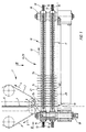
- die Transportvorrichtung schematisiert in Seitenansicht,
- Figur 2:
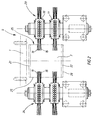
- die Stirnansicht der Transportvorrichtung in Richtung des Pfeiles II in
Figur 1, - Figur 3:
- die Draufsicht auf die Transporteinrichtung in Pfeilrichtung III in
Figur 1, - Figur 4:
- die Seitenansicht der Stapelbildungsvorrichtung,
- Figur 5:
- Draufsicht auf die Stapelbildungsvorrichtung in Pfeilrichtung V in Figur 4.
- Figure 1:
- the transport device schematically in side view,
- Figure 2:
- the front view of the transport device in the direction of arrow II in Figure 1,
- Figure 3:
- the top view of the transport device in the direction of arrow III in Figure 1,
- Figure 4:
- the side view of the stacking device,
- Figure 5:
- Top view of the stack formation device in the direction of arrow V in FIG. 4.
In Figur 1 ist ein Einschußband 1 schematisiert dargestellt, welches im wesentlichen aus zwei gegenläufig angetriebenen Transportriemen 2, 3 besteht, welche jeweils in den Pfeilrichtungen 4, 5 angetrieben sind.In Figure 1, a
Die Transportriemen 2, 3 bilden einen winzigen Förderspalt 6, in den jeweils eine Scheibe 7 in Pfeilrichtung 8 nach unten befördert wird.The
Aufgrund der hohen Geschwindigkeit der Transportriemen 2, 3 wird somit die im Förderspalt 6 liegende Scheibe 7 in Pfeilrichtung 8 zwischen die Borsten einer darunter angeordneten Transportvorrichtung 9 geschossen.Due to the high speed of the
Im gezeigten Ausführungsbeispiel besteht die Transportvorrichtung 9 aus jeweils links und rechts stehend angeordneten Umlenkrollen 16, 17, wobei über jede der Umlenkrollen 16,17 ein Bürstenband 23, 24 als Endlosband läuft und angetrieben ist.In the exemplary embodiment shown, the
Zur Erläuterung des Aufbaues jedes einzelnen Bürstenbandes 23, 24 genügt die Erläuterung eines einzigen Bürstenbandes, weil das andere Bürstenband und dessen Antrieb genau gleich ausgebildet ist.To explain the structure of each
Jedes Bürstenband 23, 24 besteht gemäß den Darstellungen in Figur 1 und 2 aus einem oberen Bürstenband 10 und einem unteren Bürstenband 11.As shown in FIGS. 1 and 2, each
Beide Bürstenbänder sind aus einem Kunststoffmaterial ausgebildet und als Zahnflachriemen ausgebildet. Auf diesem Zahnflachriemen sind über nicht näher dargestellte Besfestigungsmittel Halteblöcke 14 befestigt, welche die Borsten 13, 15 aufnehmen.Both brush belts are made of a plastic material and designed as a toothed flat belt. Holding blocks 14, which hold the
Jeder Halteblock 14 nimmt also einen Borstenbündel 13, sowie 15 auf und die Halteblöcke 14 sind paarweise vertikal übereinander angeordnet, so daß paarweise übereinander angeordnete Borstenbündel 13, 15 gebildet sind. Aus Kostengründen wurde jeweils das Bürstenband 23, 24 in die oberen und unteren Bürstenbänder 10, 11 aufgeteilt.Each holding
In einer anderen Ausgestaltung kann es vorgesehen sein, statt der geteilten Bürstenbänder 23, 24 (bestehend aus oberen und unteren Bürstenbändern 10, 11) auch jeweils ein durchgehendes Bürstenband zu verwenden.In another embodiment, instead of the divided
Die Borsten 13, 15 bestehen bevorzugt aus einem Kunststoffmaterial.The
Die Bürstenbänder 23, 24 sind in Pfeilrichtung 12 angetrieben, wobei der Antrieb über eine Antriebsachse 18 erfolgt, die von einem nicht näher dargestellten Antrieb beaufschlagt ist.The
In Figur 1 ist bei Position 19 noch dargestellt, daß im Bodenbereich einer Auflagefläche 20, die etwa dem Förderspalt 6 des Einschußbandes 1 gegenüberliegt, eine Ausschußklappe 19 angeordnet ist, welche in der Drehachse 26 drehbar gelagert ist.In Figure 1 at
Durch eine entsprechende Steuerung kann die Ausschußklappe 19 geöffnet werden, wenn fehlerhaftes Material von dem Einschußband 1 in die Transportvorrichtung 9 eingeschossen wird.The
Ansonsten werden die Scheiben 7 in Pfeilrichtung 8 mit hoher Geschwindigkeit zwischen die Borsten 13, 15 der Bürstenbänder 23, 24 eingeschossen und bleiben dort stehen. Hierbei prallen sie mit ihrer unteren Siegelnaht 22 auf die untere, bodenseitige Auflagefläche 20 auf, federn dort kurz ab und richten sich zwischen den Borsten 13, 15 aus.Otherwise, the
Die oberen Siegelnähte 21 ragen dann über das obere Bürstenband 10 hinaus.The upper sealing seams 21 then protrude beyond the
Es ist nicht dargestellt, daß im weiteren Verlauf (in Transportrichtung 12) obere Führungsbleche vorhanden sind, welche dafür sorgen, daß alle Scheiben 7 mit ihren unteren Siegelnähten 22 satt auf der Auflagefläche 20 aufstehen. Ebenso ist nicht dargestellt, daß noch seitliche, vertikale Führungsflächen vorhanden sind, welche die Scheiben 7 gemäß Figur 2 zwischen den Borsten 13, 15 etwa mittig zentrieren. Diese Führungsflächen sind in Form der seitlichen Führung 25 in Figur 2 angedeutet.It is not shown that in the further course (in the direction of transport 12) there are upper guide plates which ensure that all of the
In einer Weiterbildung der vorliegenden Erfindung kann es vorgesehen sein, daß im Bereich des Bürstenbandes 23,24 noch eine Stoppvorrichtung 31 angeordnet wird, welche verhindert, daß bei der nachgeschalteten Stapelbildungsvorrichtung 38 noch Scheiben auflaufen, die nicht mehr zu einem konkreten, gebildeten Stapel 33 gehören.In a development of the present invention, it can be provided that a
In Figur 3 ist des weiteren ein im Bereich der Stoppvorrichtung 31 angeordneter und mit dieser zusammenwirkender, vorzugsweise als Photozelle oder Lichtschranke ausgebildeter, Sensor 48 dargestellt.FIG. 3 also shows a
Diese Stoppvorrichtung 31 besteht im wesentlichen aus zwei symmetrisch einander gegenüberliegenden, liegenden Pneumatikyzlindern 27, wobei jeder Pneumatikzylinder 27 eine zugeordnete Kolbenstange 28 antreibt. Diese Kolbenstange 28 ist mit jeweils einem Stoppblech 29 verbunden, welches aus drei verschiedenen Fingern 30 besteht, die parallel und in gegenseitigem Abstand zueinander angeordnet sind, wobei der unterste Finger 30 unterhalb der untersten Borstenreihe des unteren Bürstenbandes 11, der mittlere Finger 30 zwischen den Bürstenbändern 10 und 11 und der obere Finger 30 oberhalb des oberen Bürstenbandes 10 angeordnet ist und jeweils seitlich sich an der jeweiligen Scheibe 7 anlegt.This
Dies ist aus Figur 3 zu erkennen, wo sich die Finger 30 jeweils seitlich anlegen, wobei nur der oberste Finger sichtbar ist.This can be seen from FIG. 3, where the
Hierbei sind die Finger 30 gerade in Eingriffsposition, das heißt sie stauen gerade die im Bürstenband in Pfeilrichtung 12 transportierten Scheiben auf, maximal laufen hierbei zwei bis drei Scheiben an den Stoppblechen 29 auf und werden dann nach Zurückziehen der Stoppbleche 29 aus dem Förderbereich der Transportvorrichtung 9 in Pfeilrichtung 12 weitertransportiert, bis sie bei Position 32 in den Bereich der Stapelbildungsvorrichtung 38 kommen.Here, the
Die Stapelbildungsvorrichtung 38 ist in den Figuren 4 und 5 näher beschrieben.The stacking
Es ist erkennbar, daß die Scheiben 7 in Pfeilrichtung 12 gegen eine Anschlagfläche 34 laufen, wo sie aufgestaut werden.It can be seen that the
Hierbei ist wichtig, daß mehrere Anschlagflächen 34, 35, 36, 37 gleichmäßig am Umfang verteilt eines Drehkreuzes angeordnet sind und dieses Drehkreuz aus einzelnen Fingern 45, 46 besteht, welche die jeweilige Anschlagflächen 34 - 37 bilden.It is important that a plurality of stop surfaces 34, 35, 36, 37 are evenly distributed around the circumference of a turnstile and that turnstile consists of
Beispielsweise wird ein Scheibenstapel 33 an der Anschlagfläche 34 gebildet, welche durch die Finger 45, 46 definiert wird.For example, a
Im Winkel von 90 ° versetzt hierzu sind weitere Finger 45a, 46a angeordnet, welche die Anschlagfläche 37 definieren.At an angle of 90 ° to this, further fingers 45a, 46a are arranged which define the
Das gesamte Drehkreuz ist in der Drehachse 39 schrittweise drehend angetrieben, wobei von einem Antrieb 41 ausgehend paarweise Riemen 42 vorgesehen sind, welche über eine entsprechende Umlenkrolle das Drehkreuz in Pfeilrichtung 40 schrittweise drehend antreiben.The entire turnstile is driven in a rotating manner step by step in the axis of
In der in Figur 4 gezeigten Situation laufen also die Scheiben 7 zu dem Scheibenstapel 33 auf, indem sie an der Anschlagfläche 34 aufgestaut werden. Sobald der Stapel die erforderliche Scheibenanzahl aufweist, wird das Drehkreuz in Pfeilrichtung 40 um 90 ° angetrieben, so daß der stehende Stapel 33 in den liegenden Stapel 33a übergeführt wird. Hierbei wird der liegende Scheibenstapel 33a auf einem Transportband 43 abgelegt und in Pfeilrichtung 44 abtransportiert.In the situation shown in FIG. 4, the
Wichtig hierbei ist, daß wenn der stehende Stapel 33 durch Drehung des Drehkreuzes in Pfeilrichtung 40 in den liegenden Scheibenstapel 33a übergeführt wird, daß dann keine weiteren Scheiben mehr in Pfeilrichtung 12 gegen die Stapelbildungsvorrichtung 38 transportiert werden. Zu diesem Zweck ist die vorher beschriebene Stoppvorrichtung 31 vorgesehen, die in diesem kurzen Zwischenraum mit ihren Stoppblechen 29 in den Förderbereich der Transportvorrichtung 9 eingreift und dort die geförderten Scheiben 7 zurückhält.It is important here that when the standing
Wie eingangs ausgeführt, besteht das Drehkreuz im wesentlichen aus den Fingern 45, 46 bzw. 45a, 46a, die um 90 am Umfang versetzt zueinander angeordnet sind.As stated at the beginning, the turnstile essentially consists of the
Selbstverständlich ist das Drehkreuz nicht auf eine derartige Ausführungsform beschränkt, es können beispielsweise nur zwei einandergegenüberliegende Anschlagflächen vorhanden sein, die im Winkel von 180 ° zueinander versetzt sind.Of course, the turnstile is not limited to such an embodiment; for example, there may only be two opposing stop surfaces which are offset from one another by an angle of 180 °.
Die besagten Finger 45, 45a bzw. 46, 46a werden dann an dem Transportband 43 vorbeigeschwenkt.Said
Es ist ebenso möglich, das Transportband 43 aus einzelnen Transportriemen auszubilden und die Finger 45, 46 zwischen diese Riemen zu schwenken und durch diese Riemen hindurch anstatt - wie im Ausführungsbeispiel gezeigt - am Transportband 43 außen vorbeizuführen.It is also possible to form the
Der auf dem Transportband 43 gebildete Stapel 33b wird dann einer Umverpackungsmaschine zugeführt, wo die Umverpackung um den Stapel gelegt und gesiegelt wird.The
Es ist hierzu ein Abtransportband 47 vorgesehen.For this purpose, a
- 11
- EinschußbandWeft tape
- 22nd
- TransportriemenConveyor belts
- 33rd
- TransportriemenConveyor belts
- 44th
- PfeilrichtungArrow direction
- 55
- PfeilrichtungArrow direction
- 66
- FörderspaltConveyor gap
- 77
- Scheibedisc
- 88th
- PfeilrichtungArrow direction
- 99
- TransportvorrichtungTransport device
- 1010th
- Bürstenband (oben)Brush tape (top)
- 1111
- Bürstenband (unten)Brush belt (bottom)
- 1212th
- PfeilrichtungArrow direction
- 1313
- BorstenBristles
- 1414
- HalteblechBracket
- 1515
- BorstenBristles
- 1616
- UmlenkrollePulley
- 1717th
- UmlenkrollePulley
- 1818th
- AntriebsachseDrive axle
- 1919th
- Position (Ausschußklappe)Position (reject flap)
- 2020th
- AuflageflächeContact surface
- 2121
- Siegelnaht (oben)Sealed seam (top)
- 2222
- Siegelnaht (unten)Sealed seam (bottom)
- 2323
- Bürstenband (rechts)Brush tape (right)
- 2424th
- Bürstenband (links)Brush tape (left)
- 2525th
- seitliche Führunglateral guidance
- 2626
- DrehachseAxis of rotation
- 2727
- PneumatikzylinderPneumatic cylinder
- 2828
- KolbenstangePiston rod
- 2929
- StoppblechStop plate
- 3030th
- Fingerfinger
- 3131
- StoppvorrichtungStop device
- 3232
- Position (für Drehkreuz)Position (for turnstile)
- 3333
-
Scheibenstapel 33a,33b
Disc stack - 3434
- AnschlagflächeAbutment surface
- 3535
- ""
- 3636
- ""
- 3737
- ""
- 3838
- StapelbildungsvorrichtungStacking device
- 3939
- DrehachseAxis of rotation
- 4040
- PfeilrichtungArrow direction
- 4141
- Antriebdrive
- 4242
- Riemenbelt
- 4343
- TransportbandConveyor belt
- 4444
- PfeilrichtungArrow direction
- 4545
- Finger 45aFingers 45a
- 4646
- Finger 46aFingers 46a
- 4747
- AbtransportbandConveyor belt
- 4848
- Sensorsensor
Claims (20)
Applications Claiming Priority (2)
| Application Number | Priority Date | Filing Date | Title |
|---|---|---|---|
| DE19604926A DE19604926A1 (en) | 1996-02-10 | 1996-02-10 | Disc stacker, in particular for cheese slices |
| DE19604926 | 1996-02-10 |
Publications (2)
| Publication Number | Publication Date |
|---|---|
| EP0788986A1 true EP0788986A1 (en) | 1997-08-13 |
| EP0788986B1 EP0788986B1 (en) | 2000-03-22 |
Family
ID=7785070
Family Applications (1)
| Application Number | Title | Priority Date | Filing Date |
|---|---|---|---|
| EP97101094A Expired - Lifetime EP0788986B1 (en) | 1996-02-10 | 1997-01-24 | Slice stacking device particulary for sliced cheese |
Country Status (6)
| Country | Link |
|---|---|
| US (1) | US5823318A (en) |
| EP (1) | EP0788986B1 (en) |
| JP (1) | JPH09328253A (en) |
| AT (1) | ATE190956T1 (en) |
| DE (2) | DE19604926A1 (en) |
| ES (1) | ES2145523T3 (en) |
Cited By (4)
| Publication number | Priority date | Publication date | Assignee | Title |
|---|---|---|---|---|
| WO2011120664A1 (en) | 2010-03-31 | 2011-10-06 | Eugen Fakler | Device and method for producing stacks of slices |
| CN102229386A (en) * | 2011-04-21 | 2011-11-02 | 隋秀海 | Transitional bridge for conveying belts |
| CN101613032B (en) * | 2009-06-16 | 2013-01-02 | 义乌市易开盖实业公司 | Method and device for conveying thin-plate workpieces by using synchronous belts |
| CN106044156A (en) * | 2016-07-21 | 2016-10-26 | 上海人造板机器厂有限公司 | Discharging device for medium density fiberboard production line |
Families Citing this family (11)
| Publication number | Priority date | Publication date | Assignee | Title |
|---|---|---|---|---|
| DE19709412A1 (en) | 1997-03-07 | 1998-09-10 | Natec Reich Summer Gmbh Co Kg | Packaging for perishable, flexible food slices and method for inserting the slices |
| DE19812248A1 (en) * | 1998-01-16 | 1999-07-22 | Rovema Gmbh | Bag insertion into folding boxes on conveyor |
| DE19801878A1 (en) * | 1998-01-20 | 1999-08-19 | Natec | Method and device for stacking unpacked processed cheese slices |
| DE10019069A1 (en) * | 2000-04-18 | 2001-10-25 | Optima Filling & Packaging | Device for forming stacks |
| EP1215122A1 (en) * | 2000-12-13 | 2002-06-19 | SIG Pack Systems AG | Conveyor device for making and loading groups of containers |
| US6533099B2 (en) * | 2001-03-14 | 2003-03-18 | Hytrol Conveyor Company, Inc. | Article sorting system and method |
| AU2003902499A0 (en) * | 2003-05-22 | 2003-06-05 | Scott Messenger | A conveyor belt |
| US7156222B2 (en) * | 2004-10-15 | 2007-01-02 | Campbell Wrapper Corporation | Magazine apparatus for retaining flexible bags |
| EP2035306B1 (en) * | 2006-06-16 | 2011-07-13 | SACMI Cooperativa Meccanici Imola Società Cooperativa | Conveyor |
| DE102008019028A1 (en) * | 2008-04-15 | 2009-10-22 | Hochland Natec Gmbh | Method and device for stacking packaged food slices |
| FR2939421B1 (en) * | 2008-12-05 | 2011-01-14 | Datacard Corp | ELEVATOR DEVICE FOR CUSTOMIZATION MACHINE AND CUSTOMIZATION MACHINE WITH ELEVATOR DEVICE |
Citations (6)
| Publication number | Priority date | Publication date | Assignee | Title |
|---|---|---|---|---|
| US2905341A (en) * | 1957-02-26 | 1959-09-22 | Scandia Packaging Mach | Article feeding and stacking mechanisms |
| DE8709053U1 (en) * | 1987-07-01 | 1987-09-10 | Kvm Kontroll- Und Verpackungsmaschinen Gmbh & Co Kg, 7131 Wurmberg, De | |
| US4768642A (en) * | 1987-06-16 | 1988-09-06 | Kimberly-Clark Corporation | Multiple conveyors with overlapping material handling device paths |
| WO1990006274A1 (en) * | 1988-12-02 | 1990-06-14 | Halton Oy | Method in handling of returnable bottles and device for handling of returnable bottles |
| FR2683213A1 (en) * | 1991-11-04 | 1993-05-07 | Thierion Sa Gm | Device for conveying lightweight unstable objects |
| DE4315416A1 (en) * | 1993-05-10 | 1994-11-17 | Nsm Magnettechnik Gmbh | Apparatus for the conveyance of can lids and the like over a conveying or treatment zone |
Family Cites Families (25)
| Publication number | Priority date | Publication date | Assignee | Title |
|---|---|---|---|---|
| US1807312A (en) * | 1927-01-10 | 1931-05-26 | Jr William J Henley | Continuous reversible toaster |
| US2925926A (en) * | 1955-04-21 | 1960-02-23 | Baker Perkins Ltd | Apparatus for supporting and guiding substantially flat articles |
| CH339560A (en) * | 1957-06-20 | 1959-06-30 | Sapal Plieuses Automatiques | Device for setting the edge of shelves or other similar articles |
| DE1167746B (en) * | 1961-09-28 | 1964-04-09 | Standard Elektrik Lorenz Ag | Eckumfuehrung with upright conveyor systems for flat conveyed material |
| US3288266A (en) * | 1964-03-16 | 1966-11-29 | Paper Converting Machine Co | Cartoner loader |
| DE1970462U (en) * | 1967-05-09 | 1967-10-12 | Bruno Eiting | DEVICE FOR SORTING AND PACKING PARQUET SLAMS. |
| GB1291069A (en) * | 1969-12-01 | 1972-09-27 | Jacob Salomon | Apparatus for arranging substantially laminar articles into spaced groups |
| US3675792A (en) * | 1970-12-11 | 1972-07-11 | Nat Biscuit Co | Cracker stacking and segregating apparatus |
| US3895982A (en) * | 1970-12-15 | 1975-07-22 | Trelleborgs Gummifabriks Ab | Wear protection elements for planar or curved surfaces exposed to abrasion |
| US3731789A (en) * | 1971-12-09 | 1973-05-08 | Acme Visible Records Inc | Conveyor for documents |
| US3850314A (en) * | 1972-05-31 | 1974-11-26 | Multifold Int Inc | Machine for cooling and stacking flat printed articles |
| CH570902A5 (en) * | 1973-10-02 | 1975-12-31 | Sig Schweiz Industrieges | |
| US4304326A (en) * | 1975-05-15 | 1981-12-08 | Frito-Lay, Inc. | Apparatus and method for transforming a multiple layered bed of pieces into a thinner layer |
| JPS5259463A (en) * | 1975-11-10 | 1977-05-16 | Rengo Co Ltd | Device for piling boards |
| US4194343A (en) * | 1976-01-19 | 1980-03-25 | Fmc Corporation | Dry bin filler |
| CH609303A5 (en) * | 1977-02-11 | 1979-02-28 | Sig Schweiz Industrieges | |
| US4141193A (en) * | 1977-07-12 | 1979-02-27 | Joa Curt G | Horizontal diaper grouper |
| CA1122220A (en) * | 1978-11-02 | 1982-04-20 | Hans Hoffmann-Paquotte | Process for the manufacture of an oxazole |
| CH641416A5 (en) * | 1979-12-13 | 1984-02-29 | Sig Schweiz Industrieges | DEVICE ON A PACKAGING MACHINE FOR FORMING URGENT GROUPS OF DISC-SHAPED OBJECTS. |
| FR2490601A1 (en) * | 1980-09-19 | 1982-03-26 | Agostini Ets Maurice | Small plank distributor feeding conveyor of packaging machine - feeds planks to rotating turret from stack then singly to conveyor |
| DE3406858A1 (en) * | 1984-02-25 | 1985-10-03 | OSTMA Maschinenbau GmbH, 5352 Zülpich | METHOD AND DEVICE FOR TRANSPORTING FLAT BAGS FILLED WITH GRAZY OR FLOWABLE GOODS TO A STACKING POINT, IN PARTICULAR. A PACKAGING CONTAINER |
| US5176244A (en) * | 1991-09-16 | 1993-01-05 | Curt G. Joa, Inc. | High speed variable count mechanical stacker |
| US5331874A (en) * | 1991-10-16 | 1994-07-26 | Universal Frozen Foods, Inc | Cutting apparatus |
| DE4204987C2 (en) * | 1992-02-19 | 1995-04-13 | Natec Reich Summer Gmbh Co Kg | Device for cutting and stacking disc-shaped individual packs |
| US5687833A (en) * | 1995-05-25 | 1997-11-18 | Dalessio, Jr.; Frederick P. | Support roller and workpiece conveying system |
-
1996
- 1996-02-10 DE DE19604926A patent/DE19604926A1/en not_active Withdrawn
- 1996-10-31 US US08/741,653 patent/US5823318A/en not_active Expired - Lifetime
-
1997
- 1997-01-24 DE DE59701290T patent/DE59701290D1/en not_active Expired - Lifetime
- 1997-01-24 ES ES97101094T patent/ES2145523T3/en not_active Expired - Lifetime
- 1997-01-24 AT AT97101094T patent/ATE190956T1/en not_active IP Right Cessation
- 1997-01-24 EP EP97101094A patent/EP0788986B1/en not_active Expired - Lifetime
- 1997-02-07 JP JP9025114A patent/JPH09328253A/en active Pending
Patent Citations (6)
| Publication number | Priority date | Publication date | Assignee | Title |
|---|---|---|---|---|
| US2905341A (en) * | 1957-02-26 | 1959-09-22 | Scandia Packaging Mach | Article feeding and stacking mechanisms |
| US4768642A (en) * | 1987-06-16 | 1988-09-06 | Kimberly-Clark Corporation | Multiple conveyors with overlapping material handling device paths |
| DE8709053U1 (en) * | 1987-07-01 | 1987-09-10 | Kvm Kontroll- Und Verpackungsmaschinen Gmbh & Co Kg, 7131 Wurmberg, De | |
| WO1990006274A1 (en) * | 1988-12-02 | 1990-06-14 | Halton Oy | Method in handling of returnable bottles and device for handling of returnable bottles |
| FR2683213A1 (en) * | 1991-11-04 | 1993-05-07 | Thierion Sa Gm | Device for conveying lightweight unstable objects |
| DE4315416A1 (en) * | 1993-05-10 | 1994-11-17 | Nsm Magnettechnik Gmbh | Apparatus for the conveyance of can lids and the like over a conveying or treatment zone |
Cited By (7)
| Publication number | Priority date | Publication date | Assignee | Title |
|---|---|---|---|---|
| CN101613032B (en) * | 2009-06-16 | 2013-01-02 | 义乌市易开盖实业公司 | Method and device for conveying thin-plate workpieces by using synchronous belts |
| WO2011120664A1 (en) | 2010-03-31 | 2011-10-06 | Eugen Fakler | Device and method for producing stacks of slices |
| DE102010013509A1 (en) | 2010-03-31 | 2011-12-15 | Eugen Fakler | Apparatus and method for producing disk stacks |
| DE102010013509B4 (en) * | 2010-03-31 | 2012-06-14 | Eugen Fakler | Apparatus and method for producing disk stacks |
| CN102229386A (en) * | 2011-04-21 | 2011-11-02 | 隋秀海 | Transitional bridge for conveying belts |
| CN102229386B (en) * | 2011-04-21 | 2012-11-21 | 牡丹江木工机械(厂)有限责任公司 | Transitional bridge for conveying belts |
| CN106044156A (en) * | 2016-07-21 | 2016-10-26 | 上海人造板机器厂有限公司 | Discharging device for medium density fiberboard production line |
Also Published As
| Publication number | Publication date |
|---|---|
| DE19604926A1 (en) | 1997-08-14 |
| ATE190956T1 (en) | 2000-04-15 |
| ES2145523T3 (en) | 2000-07-01 |
| EP0788986B1 (en) | 2000-03-22 |
| JPH09328253A (en) | 1997-12-22 |
| DE59701290D1 (en) | 2000-04-27 |
| US5823318A (en) | 1998-10-20 |
Similar Documents
| Publication | Publication Date | Title |
|---|---|---|
| EP0559846B2 (en) | Device for turning a sheet with a simultaneous change in the direction of transport | |
| EP0788986A1 (en) | Slice stacking device particulary for sliced cheese | |
| DE3144449A1 (en) | DEVICE FOR GROUPING OBJECTS, IN PARTICULAR UPRIGHT BOTTLES | |
| DE2913077C2 (en) | ||
| DE3736868C2 (en) | ||
| DE4204987C2 (en) | Device for cutting and stacking disc-shaped individual packs | |
| DE3920407C2 (en) | ||
| DE3018683A1 (en) | DEVICE FOR ALIGNING CHIPS IN THE PRODUCTION OF CHIPBOARDS | |
| DE2909831A1 (en) | DEVICE AND METHOD FOR UNDER-GRADING STAFFLING LEAFS OR PACKAGES | |
| CH295541A (en) | Device for upright stacking of flat, flexible objects. | |
| DE102014005942A1 (en) | Method for grouping articles into article poles and grouping device and packaging machine with such | |
| DE3530624A1 (en) | Device for sorting articles such as documents or similar two-dimensional material, packages or similar relatively small piece good items etc. | |
| DE3839304C2 (en) | ||
| DE3706042A1 (en) | COIN STACKING DEVICE | |
| DE2344813A1 (en) | DEVICE FOR FILING SHEETS | |
| DE2136692A1 (en) | Method and device for collecting and transporting Be holders | |
| DE2401530B2 (en) | DEVICE FOR SUPPLYING INSERTS, E.G. FROM NEWSPAPER PRE-PRINTING TO A SINGLEIZING DEVICE | |
| EP1726552A1 (en) | Device for collecting printed products | |
| EP0059840A2 (en) | Machine for stacking and packing flat articles | |
| EP0591099A1 (en) | Method and device for making tied stacks of paper products | |
| DE2935263A1 (en) | Automatic book-stacking machine - holds books between rotary punches on top and bottom conveyors | |
| DE2109468C2 (en) | Folding machine for folding the flaps of folding boxes | |
| DE102010013509B4 (en) | Apparatus and method for producing disk stacks | |
| DE10143897A1 (en) | Device for separating the cardboard parts from a waste paper batch | |
| DE3926966C2 (en) |
Legal Events
| Date | Code | Title | Description |
|---|---|---|---|
| PUAI | Public reference made under article 153(3) epc to a published international application that has entered the european phase |
Free format text: ORIGINAL CODE: 0009012 |
|
| AK | Designated contracting states |
Kind code of ref document: A1 Designated state(s): AT BE CH DE DK ES FI FR GB GR IE IT LI LU MC NL PT SE |
|
| 17P | Request for examination filed |
Effective date: 19980206 |
|
| 17Q | First examination report despatched |
Effective date: 19981102 |
|
| GRAG | Despatch of communication of intention to grant |
Free format text: ORIGINAL CODE: EPIDOS AGRA |
|
| GRAG | Despatch of communication of intention to grant |
Free format text: ORIGINAL CODE: EPIDOS AGRA |
|
| GRAH | Despatch of communication of intention to grant a patent |
Free format text: ORIGINAL CODE: EPIDOS IGRA |
|
| GRAH | Despatch of communication of intention to grant a patent |
Free format text: ORIGINAL CODE: EPIDOS IGRA |
|
| GRAA | (expected) grant |
Free format text: ORIGINAL CODE: 0009210 |
|
| AK | Designated contracting states |
Kind code of ref document: B1 Designated state(s): AT BE CH DE DK ES FI FR GB GR IE IT LI LU MC NL PT SE |
|
| PG25 | Lapsed in a contracting state [announced via postgrant information from national office to epo] |
Ref country code: SE Free format text: THE PATENT HAS BEEN ANNULLED BY A DECISION OF A NATIONAL AUTHORITY Effective date: 20000322 Ref country code: NL Free format text: LAPSE BECAUSE OF FAILURE TO SUBMIT A TRANSLATION OF THE DESCRIPTION OR TO PAY THE FEE WITHIN THE PRESCRIBED TIME-LIMIT Effective date: 20000322 Ref country code: FI Free format text: LAPSE BECAUSE OF FAILURE TO SUBMIT A TRANSLATION OF THE DESCRIPTION OR TO PAY THE FEE WITHIN THE PRESCRIBED TIME-LIMIT Effective date: 20000322 |
|
| REF | Corresponds to: |
Ref document number: 190956 Country of ref document: AT Date of ref document: 20000415 Kind code of ref document: T |
|
| REG | Reference to a national code |
Ref country code: CH Ref legal event code: EP |
|
| REF | Corresponds to: |
Ref document number: 59701290 Country of ref document: DE Date of ref document: 20000427 |
|
| REG | Reference to a national code |
Ref country code: IE Ref legal event code: FG4D Free format text: GERMAN |
|
| REG | Reference to a national code |
Ref country code: CH Ref legal event code: NV Representative=s name: LUCHS & PARTNER PATENTANWAELTE |
|
| ITF | It: translation for a ep patent filed |
Owner name: STUDIO INTERN. DOTT. COPPI S.N.C. |
|
| PG25 | Lapsed in a contracting state [announced via postgrant information from national office to epo] |
Ref country code: DK Free format text: LAPSE BECAUSE OF FAILURE TO SUBMIT A TRANSLATION OF THE DESCRIPTION OR TO PAY THE FEE WITHIN THE PRESCRIBED TIME-LIMIT Effective date: 20000622 |
|
| PG25 | Lapsed in a contracting state [announced via postgrant information from national office to epo] |
Ref country code: PT Free format text: LAPSE BECAUSE OF FAILURE TO SUBMIT A TRANSLATION OF THE DESCRIPTION OR TO PAY THE FEE WITHIN THE PRESCRIBED TIME-LIMIT Effective date: 20000623 Ref country code: GR Free format text: LAPSE BECAUSE OF FAILURE TO SUBMIT A TRANSLATION OF THE DESCRIPTION OR TO PAY THE FEE WITHIN THE PRESCRIBED TIME-LIMIT Effective date: 20000623 |
|
| REG | Reference to a national code |
Ref country code: ES Ref legal event code: FG2A Ref document number: 2145523 Country of ref document: ES Kind code of ref document: T3 |
|
| GBT | Gb: translation of ep patent filed (gb section 77(6)(a)/1977) |
Effective date: 20000619 |
|
| ET | Fr: translation filed | ||
| NLV1 | Nl: lapsed or annulled due to failure to fulfill the requirements of art. 29p and 29m of the patents act | ||
| PG25 | Lapsed in a contracting state [announced via postgrant information from national office to epo] |
Ref country code: IE Free format text: LAPSE BECAUSE OF NON-PAYMENT OF DUE FEES Effective date: 20010109 |
|
| PLBE | No opposition filed within time limit |
Free format text: ORIGINAL CODE: 0009261 |
|
| STAA | Information on the status of an ep patent application or granted ep patent |
Free format text: STATUS: NO OPPOSITION FILED WITHIN TIME LIMIT |
|
| PG25 | Lapsed in a contracting state [announced via postgrant information from national office to epo] |
Ref country code: LU Free format text: LAPSE BECAUSE OF NON-PAYMENT OF DUE FEES Effective date: 20010124 |
|
| PG25 | Lapsed in a contracting state [announced via postgrant information from national office to epo] |
Ref country code: MC Free format text: LAPSE BECAUSE OF NON-PAYMENT OF DUE FEES Effective date: 20010131 Ref country code: BE Free format text: LAPSE BECAUSE OF NON-PAYMENT OF DUE FEES Effective date: 20010131 |
|
| 26N | No opposition filed | ||
| BERE | Be: lapsed |
Owner name: NATEC REICH SUMMER G.M.B.H. & CO. K.G. Effective date: 20010131 |
|
| REG | Reference to a national code |
Ref country code: GB Ref legal event code: IF02 |
|
| PGFP | Annual fee paid to national office [announced via postgrant information from national office to epo] |
Ref country code: AT Payment date: 20040119 Year of fee payment: 8 |
|
| PGFP | Annual fee paid to national office [announced via postgrant information from national office to epo] |
Ref country code: GB Payment date: 20040120 Year of fee payment: 8 |
|
| PG25 | Lapsed in a contracting state [announced via postgrant information from national office to epo] |
Ref country code: GB Free format text: LAPSE BECAUSE OF NON-PAYMENT OF DUE FEES Effective date: 20050124 Ref country code: AT Free format text: LAPSE BECAUSE OF NON-PAYMENT OF DUE FEES Effective date: 20050124 |
|
| REG | Reference to a national code |
Ref country code: CH Ref legal event code: PFA Owner name: NATEC GMBH Free format text: NATEC REICH, SUMMER GMBH & CO. KG#KOLPINGSTRASSE 32#88178 HEIMENKIRCH (DE) -TRANSFER TO- NATEC GMBH#KOLPINGSTRASSE 32#88178 HEIMENKIRCH (DE) |
|
| REG | Reference to a national code |
Ref country code: ES Ref legal event code: PC2A |
|
| REG | Reference to a national code |
Ref country code: FR Ref legal event code: CD |
|
| GBPC | Gb: european patent ceased through non-payment of renewal fee |
Effective date: 20050124 |
|
| PGFP | Annual fee paid to national office [announced via postgrant information from national office to epo] |
Ref country code: IT Payment date: 20090130 Year of fee payment: 13 |
|
| PGFP | Annual fee paid to national office [announced via postgrant information from national office to epo] |
Ref country code: FR Payment date: 20090130 Year of fee payment: 13 |
|
| REG | Reference to a national code |
Ref country code: FR Ref legal event code: ST Effective date: 20100930 |
|
| PG25 | Lapsed in a contracting state [announced via postgrant information from national office to epo] |
Ref country code: FR Free format text: LAPSE BECAUSE OF NON-PAYMENT OF DUE FEES Effective date: 20100201 |
|
| PG25 | Lapsed in a contracting state [announced via postgrant information from national office to epo] |
Ref country code: IT Free format text: LAPSE BECAUSE OF NON-PAYMENT OF DUE FEES Effective date: 20100124 |
|
| PGFP | Annual fee paid to national office [announced via postgrant information from national office to epo] |
Ref country code: ES Payment date: 20120130 Year of fee payment: 16 |
|
| REG | Reference to a national code |
Ref country code: ES Ref legal event code: FD2A Effective date: 20140324 |
|
| PG25 | Lapsed in a contracting state [announced via postgrant information from national office to epo] |
Ref country code: ES Free format text: LAPSE BECAUSE OF NON-PAYMENT OF DUE FEES Effective date: 20130125 |
|
| PGFP | Annual fee paid to national office [announced via postgrant information from national office to epo] |
Ref country code: DE Payment date: 20150114 Year of fee payment: 19 Ref country code: CH Payment date: 20150123 Year of fee payment: 19 |
|
| REG | Reference to a national code |
Ref country code: DE Ref legal event code: R119 Ref document number: 59701290 Country of ref document: DE |
|
| REG | Reference to a national code |
Ref country code: CH Ref legal event code: PL |
|
| PG25 | Lapsed in a contracting state [announced via postgrant information from national office to epo] |
Ref country code: LI Free format text: LAPSE BECAUSE OF NON-PAYMENT OF DUE FEES Effective date: 20160131 Ref country code: CH Free format text: LAPSE BECAUSE OF NON-PAYMENT OF DUE FEES Effective date: 20160131 Ref country code: DE Free format text: LAPSE BECAUSE OF NON-PAYMENT OF DUE FEES Effective date: 20160802 |