EP0789406A1 - A heat sensitive jacket label for a battery and a battery with the same - Google Patents
A heat sensitive jacket label for a battery and a battery with the same Download PDFInfo
- Publication number
- EP0789406A1 EP0789406A1 EP97300094A EP97300094A EP0789406A1 EP 0789406 A1 EP0789406 A1 EP 0789406A1 EP 97300094 A EP97300094 A EP 97300094A EP 97300094 A EP97300094 A EP 97300094A EP 0789406 A1 EP0789406 A1 EP 0789406A1
- Authority
- EP
- European Patent Office
- Prior art keywords
- heat
- heat sensitive
- battery
- base
- layer
- Prior art date
- Legal status (The legal status is an assumption and is not a legal conclusion. Google has not performed a legal analysis and makes no representation as to the accuracy of the status listed.)
- Granted
Links
Images

Classifications
-
- H—ELECTRICITY
- H01—ELECTRIC ELEMENTS
- H01M—PROCESSES OR MEANS, e.g. BATTERIES, FOR THE DIRECT CONVERSION OF CHEMICAL ENERGY INTO ELECTRICAL ENERGY
- H01M50/00—Constructional details or processes of manufacture of the non-active parts of electrochemical cells other than fuel cells, e.g. hybrid cells
- H01M50/20—Mountings; Secondary casings or frames; Racks, modules or packs; Suspension devices; Shock absorbers; Transport or carrying devices; Holders
-
- B—PERFORMING OPERATIONS; TRANSPORTING
- B32—LAYERED PRODUCTS
- B32B—LAYERED PRODUCTS, i.e. PRODUCTS BUILT-UP OF STRATA OF FLAT OR NON-FLAT, e.g. CELLULAR OR HONEYCOMB, FORM
- B32B27/00—Layered products comprising a layer of synthetic resin
- B32B27/06—Layered products comprising a layer of synthetic resin as the main or only constituent of a layer, which is next to another layer of the same or of a different material
- B32B27/08—Layered products comprising a layer of synthetic resin as the main or only constituent of a layer, which is next to another layer of the same or of a different material of synthetic resin
-
- H—ELECTRICITY
- H01—ELECTRIC ELEMENTS
- H01M—PROCESSES OR MEANS, e.g. BATTERIES, FOR THE DIRECT CONVERSION OF CHEMICAL ENERGY INTO ELECTRICAL ENERGY
- H01M50/00—Constructional details or processes of manufacture of the non-active parts of electrochemical cells other than fuel cells, e.g. hybrid cells
- H01M50/10—Primary casings, jackets or wrappings of a single cell or a single battery
- H01M50/116—Primary casings, jackets or wrappings of a single cell or a single battery characterised by the material
- H01M50/117—Inorganic material
- H01M50/119—Metals
-
- H—ELECTRICITY
- H01—ELECTRIC ELEMENTS
- H01M—PROCESSES OR MEANS, e.g. BATTERIES, FOR THE DIRECT CONVERSION OF CHEMICAL ENERGY INTO ELECTRICAL ENERGY
- H01M50/00—Constructional details or processes of manufacture of the non-active parts of electrochemical cells other than fuel cells, e.g. hybrid cells
- H01M50/10—Primary casings, jackets or wrappings of a single cell or a single battery
- H01M50/116—Primary casings, jackets or wrappings of a single cell or a single battery characterised by the material
- H01M50/121—Organic material
-
- H—ELECTRICITY
- H01—ELECTRIC ELEMENTS
- H01M—PROCESSES OR MEANS, e.g. BATTERIES, FOR THE DIRECT CONVERSION OF CHEMICAL ENERGY INTO ELECTRICAL ENERGY
- H01M50/00—Constructional details or processes of manufacture of the non-active parts of electrochemical cells other than fuel cells, e.g. hybrid cells
- H01M50/10—Primary casings, jackets or wrappings of a single cell or a single battery
- H01M50/116—Primary casings, jackets or wrappings of a single cell or a single battery characterised by the material
- H01M50/124—Primary casings, jackets or wrappings of a single cell or a single battery characterised by the material having a layered structure
- H01M50/126—Primary casings, jackets or wrappings of a single cell or a single battery characterised by the material having a layered structure comprising three or more layers
- H01M50/129—Primary casings, jackets or wrappings of a single cell or a single battery characterised by the material having a layered structure comprising three or more layers with two or more layers of only organic material
-
- H—ELECTRICITY
- H01—ELECTRIC ELEMENTS
- H01M—PROCESSES OR MEANS, e.g. BATTERIES, FOR THE DIRECT CONVERSION OF CHEMICAL ENERGY INTO ELECTRICAL ENERGY
- H01M50/00—Constructional details or processes of manufacture of the non-active parts of electrochemical cells other than fuel cells, e.g. hybrid cells
- H01M50/10—Primary casings, jackets or wrappings of a single cell or a single battery
- H01M50/131—Primary casings, jackets or wrappings of a single cell or a single battery characterised by physical properties, e.g. gas-permeability or size
-
- B—PERFORMING OPERATIONS; TRANSPORTING
- B32—LAYERED PRODUCTS
- B32B—LAYERED PRODUCTS, i.e. PRODUCTS BUILT-UP OF STRATA OF FLAT OR NON-FLAT, e.g. CELLULAR OR HONEYCOMB, FORM
- B32B2307/00—Properties of the layers or laminate
- B32B2307/20—Properties of the layers or laminate having particular electrical or magnetic properties, e.g. piezoelectric
- B32B2307/206—Insulating
-
- B—PERFORMING OPERATIONS; TRANSPORTING
- B32—LAYERED PRODUCTS
- B32B—LAYERED PRODUCTS, i.e. PRODUCTS BUILT-UP OF STRATA OF FLAT OR NON-FLAT, e.g. CELLULAR OR HONEYCOMB, FORM
- B32B2307/00—Properties of the layers or laminate
- B32B2307/30—Properties of the layers or laminate having particular thermal properties
- B32B2307/306—Resistant to heat
-
- B—PERFORMING OPERATIONS; TRANSPORTING
- B32—LAYERED PRODUCTS
- B32B—LAYERED PRODUCTS, i.e. PRODUCTS BUILT-UP OF STRATA OF FLAT OR NON-FLAT, e.g. CELLULAR OR HONEYCOMB, FORM
- B32B2307/00—Properties of the layers or laminate
- B32B2307/70—Other properties
- B32B2307/732—Dimensional properties
- B32B2307/734—Dimensional stability
- B32B2307/736—Shrinkable
-
- B—PERFORMING OPERATIONS; TRANSPORTING
- B32—LAYERED PRODUCTS
- B32B—LAYERED PRODUCTS, i.e. PRODUCTS BUILT-UP OF STRATA OF FLAT OR NON-FLAT, e.g. CELLULAR OR HONEYCOMB, FORM
- B32B2457/00—Electrical equipment
- B32B2457/10—Batteries
-
- Y—GENERAL TAGGING OF NEW TECHNOLOGICAL DEVELOPMENTS; GENERAL TAGGING OF CROSS-SECTIONAL TECHNOLOGIES SPANNING OVER SEVERAL SECTIONS OF THE IPC; TECHNICAL SUBJECTS COVERED BY FORMER USPC CROSS-REFERENCE ART COLLECTIONS [XRACs] AND DIGESTS
- Y02—TECHNOLOGIES OR APPLICATIONS FOR MITIGATION OR ADAPTATION AGAINST CLIMATE CHANGE
- Y02E—REDUCTION OF GREENHOUSE GAS [GHG] EMISSIONS, RELATED TO ENERGY GENERATION, TRANSMISSION OR DISTRIBUTION
- Y02E60/00—Enabling technologies; Technologies with a potential or indirect contribution to GHG emissions mitigation
- Y02E60/10—Energy storage using batteries
-
- Y—GENERAL TAGGING OF NEW TECHNOLOGICAL DEVELOPMENTS; GENERAL TAGGING OF CROSS-SECTIONAL TECHNOLOGIES SPANNING OVER SEVERAL SECTIONS OF THE IPC; TECHNICAL SUBJECTS COVERED BY FORMER USPC CROSS-REFERENCE ART COLLECTIONS [XRACs] AND DIGESTS
- Y10—TECHNICAL SUBJECTS COVERED BY FORMER USPC
- Y10T—TECHNICAL SUBJECTS COVERED BY FORMER US CLASSIFICATION
- Y10T428/00—Stock material or miscellaneous articles
- Y10T428/28—Web or sheet containing structurally defined element or component and having an adhesive outermost layer
- Y10T428/2813—Heat or solvent activated or sealable
- Y10T428/2817—Heat sealable
-
- Y—GENERAL TAGGING OF NEW TECHNOLOGICAL DEVELOPMENTS; GENERAL TAGGING OF CROSS-SECTIONAL TECHNOLOGIES SPANNING OVER SEVERAL SECTIONS OF THE IPC; TECHNICAL SUBJECTS COVERED BY FORMER USPC CROSS-REFERENCE ART COLLECTIONS [XRACs] AND DIGESTS
- Y10—TECHNICAL SUBJECTS COVERED BY FORMER USPC
- Y10T—TECHNICAL SUBJECTS COVERED BY FORMER US CLASSIFICATION
- Y10T428/00—Stock material or miscellaneous articles
- Y10T428/28—Web or sheet containing structurally defined element or component and having an adhesive outermost layer
- Y10T428/2848—Three or more layers
Definitions
- the present invention relates to a heat sensitive jacket label for a battery, and an improvement in a battery with such a heat sensitive jacket label.
- the sizes of batteries such as outer diameters and lengths are standardized in the JIS (Japanese Industrial Standards) or IEC. Therefore, the achievement of a battery having a higher capacity depends on a successful decrease in the volume of the jacket.
- the conventional metal jacket has been replaced by a jacket label which consists of a heat-shrinking resin film as its base, a print layer formed on one surface of the base, and a pressure sensitive adhesive layer formed on the other surface of the base.
- This jacket label is applied to a dry battery by wrapping it around the outer circumference of the dry battery with the adhesive layer inward, and then heat-shrinking the base to cling to the dry battery.
- the jacket label is thinner than the conventional metal jacket, so that the dry battery can have a much larger capacity.
- this type of jacket label has the following drawback.
- the adhesive layer which is formed on the other surface of the base has a release paper on its surface.
- the release paper which is useless to a battery, not only raises the cost of the battery but also requires troublesome peeling off, which accordingly decreases the operation efficiency.
- a hot melt adhesive or a heat sensitive adhesive is now used in a heat sensitive jacket label. Since the heat sensitive adhesive remains nonadhesive unless a certain degree of heat is applied, no release paper is needed.
- the heat sensitive jacket label also has other drawbacks as follows.
- the heat sensitive adhesive is activated at too high a temperature, the heat-shrinking resin film which is used as the base shrinks. This causes the jacket label to have wrinkles or distortion when it is wrapped around the dry battery, which deteriorates its appearance.
- the jacket label is applied before the heat sensitive adhesive becomes sufficiently adhesive, which causes defective adhesion.
- this type of jacket label is provided with a metal deposit layer such as aluminum on the back surface of the base in order to give a high metallic gloss to the jacket label, and accordingly to enhance the appearance of the print on the base surface.
- the dissolution of aluminum results from the development of small pinholes on the heat sensitive adhesive layer while the heat sensitive adhesive is heat-melted and then cooled to make the jacket label stick on a metal case.
- the heat sensitive adhesive layer has such pinholes, moisture in the air forms local cells between the deposited aluminum and the surface of the battery case which is made of iron or nickel plated steel in the case of an alkaline dry battery. As a result, aluminum is dissolved.
- the dissolution often occurs particularly under high-temperature and high-humidity conditions.
- a main aim of the present invention is to provide a heat sensitive jacket label for a battery which is economical to apply to the battery, and has a good appearance, without the above-described problems that are caused by the use of a heat sensitive adhesive.
- Another aim of the present invention is to provide a battery with a jacket label which has no change in quality and keeps good appearance with metallic gloss while the battery is being stored.
- the present invention provides a heat sensitive jacket label for a battery comprising a heat-shrinking synthetic resin film as its base and a heat sensitive adhesive layer provided on one surface of the base, and the temperature for the base to heat-shrink is at least 15°C higher than the temperature for the heat sensitive adhesive layer to develop adhesion.
- the heat sensitive jacket label for a battery further comprises a metal deposit layer provided on one surface of the base, and a heat-resistant electrically insulating layer provided on the metal deposit, and the above-mentioned heat sensitive adhesive layer is provided on the heat-resistant electrically insulating layer.
- the heat sensitive jacket label for a battery further comprises a metal deposit layer made of silver, tin, or nickel and the above-mentioned heat sensitive adhesive layer is provided on the metal deposit layer.
- the present invention provides a battery with the above-described heat sensitive jacket label.
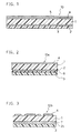
- Fig. 1 is a sectional view of the construction of a heat sensitive jacket label of the present invention.
- Fig. 2 is a sectional view of the construction of another heat sensitive jacket label of the present invention.
- Fig. 3 is a sectional view of the construction of still another heat sensitive jacket label of the present invention.
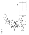
- Fig. 4 is a schematic view of a device for applying heat sensitive jacket labels to batteries.
- Fig. 5 is a longitudinal sectional view of a battery to which a jacket label has been applied.
- Fig. 6 is a cross-sectional view of the same battery.
- Fig. 7 is a longitudinal sectional view of a battery with a heat-shrunk heat sensitive jacket label.
- the present invention is directed to a heat sensitive jacket label for a battery which includes a heat-shrinking synthetic resin film as its base and a heat sensitive adhesive layer with which the base adheres on the battery, and also directed to a battery with such a heat sensitive jacket label.
- materials for the base and the heat sensitive adhesive layer are so selected that the temperature for inducing a heat-shrink of the base is higher than the temperature for effecting adhesion of the heat sensitive adhesive layer by at least 15°C.
- the temperature for inducing a heat-shrink of the base refers to a temperature at which the base shrinks at least 1%.
- the temperature for inducing a heat-shrink of the base is higher than the temperature for the heat sensitive adhesive layer to become adhesive by at least 20°C.
- the temperature for the heat sensitive adhesive layer to become adhesive, that is, to be activated is 60°C or above.
- the jacket label can be adhered to a battery without the base heat-shrinking.
- the jacket label is applied to the battery when the temperature is heated high enough for the base to heat-shrink. After this, the heat sensitive jacket label is stuck to the battery without wrinkles or distortion on the printed area and has a good appearance.
- a metal layer is provided to give a high metallic gloss at the back surface of the base.
- the metal layer is prevented from corroding by providing a heat-resistant electrically insulating layer between the metal layer and the heat sensitive adhesive layer.
- the metal layer can be made of silver, tin, or nickel, which is more noble than the material for the battery case.
- the heat sensitive jacket label is applicable to primary batteries such as cylindrical manganese dry batteries, alkaline batteries, and lithium batteries and also to secondary batteries such as nickel-metal hydride storage batteries, and lithium ion batteries.
- Fig. 1 shows the construction of a heat sensitive jacket label of the present invention.
- the heat sensitive jacket label 10 is composed of a base 1, a metal layer 2, a heat sensitive adhesive layer 3, a print layer 4, and a varnish layer 5.
- the base 1 is made of a heat-shrinking resin film such as polyethylene terephthalate.
- the metal layer 2 is formed on the back surface of the base 1 by depositing aluminum or another metal.
- the heat sensitive adhesive layer 3 is provided beneath the metal layer 2.
- the print layer 4 is formed on the front surface of the base 1.
- the varnish layer 5 is formed on the outer surface of the print layer 4 by spreading varnish thereon.
- the heat-shrinking resin film which composes the base 1 can be a mono- or multi-layered film which is made of polyester such as polyethylene terephthalate, polyvinyl chloride, polyethylene, polypropylene, or polyamide.
- the preferable thickness of the film is 10 to 200 ⁇ m, and more preferably 30 to 60 ⁇ m.
- polyester such as polyethylene terephthalate is most suitable for the base 1 because it has excellent strength and rigidity, and generates no poisonous gas when it is burned.
- the heat-shrinking film is formed by being uniaxially or biaxially oriented so that it can shrink largely in the circumferential direction of a battery when the film is wrapped around it.
- the metal layer 2 is formed by vacuum depositing aluminum in a thickness of about 0.01 to 0.1 pm.
- the heat sensitive adhesive layer 3 can be a mixture of one or more hot melt resins and various additives.
- the hot melt resins include an ethylene-vinylacetate copolymer, an ethylene-acrylic acid copolymer, an ethylene-methacrylic acid copolymer, an ionomer, and low-density polyethylene.
- the additives include tackifiers such as terpene resin and petroleum resin, a plasticizer, a stabilizer, and a lubricant.
- an anchor coat layer on the base 1 and on the aluminum deposit layer 2 in order to improve the adhesion between the base 1 and the aluminum deposit layer 2 and between the aluminum deposit layer 2 and the heat sensitive adhesive layer 3, respectively.
- the print layer 4 has some designs such as a brand name or illustration which has been formed by the relief rotary printing, the silk-screen printing, the gravure printing, or another well-known printing method.
- Another anchor coat layer may be provided between the print layer 4 and the base 1 for the same reason as described above.
- the printing ink to be used for the print layer 4 can be of any kind.
- an ultraviolet-setting ink having excellent heat-resistance is used, the print layer 4 is hardly damaged by the heat when the heat sensitive adhesive layer 3 is activated or the base 1 heat-shrinks.
- the varnish layer 5 is composed of transparent varnish which protects the print layer 4 and also gives it a high gloss.
- the transparent varnish can be of any kind such as the widely-used synthetic resin.
- heat-resistant varnish such as ultraviolet-setting varnish is used, the print layer 4 is hardly damaged by the heat like the ultraviolet-setting ink.
- the aluminum deposit layer 2 is formed by vacuum depositing aluminum in a thickness of about 0.05 ⁇ m on a surface of the base 1 which is made of a heat-shrinking polyethylene terephthalate film having a thickness around 50 ⁇ m.
- the film for the base 1 has been subjected to a drawing or stretching process at an appropriate rate so that it can heat-shrink in the longitudinal direction.
- the heat sensitive adhesive layer 3 is formed on the surface of the anchor coat by melting and extruding a hot melt resin in a thickness of 20 ⁇ m.
- the hot melt resin is mainly composed of an ethylene-vinylacetate copolymer.
- the print layer 4 is formed on the other surface of the polyethylene terephthalate film by printing various display designs with the use of a relief rotary printer.
- the varnish layer 5 is formed by spreading transparent varnish over the surface of the print layer 4.
- a number of heat sensitive jacket labels are formed on the rolled film, and the film is cut at predetermined positions so as to obtain the heat sensitive jacket label 10.
- the film is so cut that the longitudinal direction of the film corresponds to the circumference of the heat sensitive jacket label 10.
- the basic difference between the heat sensitive jacket label 10 and the heat sensitive jacket label 10a is that the latter is provided with a heat-resistant electrically insulating layer 6 between the metal layer 2 having deposited aluminum and the heat sensitive adhesive layer 3.
- the varnish layer 5 is not shown in Fig. 2, it may be added if necessary.
- the electrically insulating layer 6 is formed by melting and extruding the resin in a thickness of 5 to 30 ⁇ m.
- the resin can be low-density polyethylene, polypropylene, an ethylene-methacrylic acid copolymer, an ethylene-acrylic acid copolymer, an ethylene-methyl methacrylate copolymer, or an ethylene-vinylacetate copolymer.
- a heat-shrinking film which is made of one of these resins can be accumulated by dry lamination or the like.
- an ethylene-methacrylic acid copolymer As still another method, it is possible to coat a solution of an ethylene-methacrylic acid copolymer, an ethylene-vinylacetate copolymer, or polyester urethane resin.
- These resins to be used as the electrically insulating layer 6 contain substantially no additives such as tackifiers, and have a higher softening point than the resin used for the adhesive layer 3. It is preferable that the softening point is 80°C or above in order to resist the use and the preservation of the battery in high-temperature conditions and the heat which is applied to make the heat sensitive jacket label 10a heat-shrink.
- the above-described construction efficiently prevents the dissolution of the metal layer 2 even if the battery is preserved at high-temperature and high-humidity conditions, thereby preventing the loss of the metallic gloss of the heat sensitive jacket label 10a.
- the jacket label 10a which is heat-shrinkable is wrapped around the battery while the heat sensitive adhesive layer 3 which is formed on the back surface of the base is melted by heat.
- the adhesive is hardened by cooling, and as a result, the jacket label 10a which is wrapped around the battery adheres to the battery. While the adhesive is hardened by cooling, the heat sensitive adhesive layer 3 develops pinholes or cracks.
- the metal layer 2 comes in contact with the battery case which is made of nickel plated steel or the like which also serves as a positive electrode terminal. Then, in the high-temperature and high-humidity conditions, local cells are generated between the battery case and the metal layer 2 through moisture in the air. As a result, aluminum is dissolved, and the jacket label 10a partly loses the metallic gloss.
- the dissolution of aluminum tends to occur particularly at the top and bottom corners covering both ends of the jacket label 10a which protrude beyond the top and the bottom ends of the battery.
- the top and bottom corners have a high heat shrinkage degree and are vulnerable to the pressure of heat shrinkage. The cause of this is considered that at the top and bottom corners the heat sensitive adhesive layer 3 is pushed away because it heat-shrinks while being melted. Consequently, the metal layer 2 and the battery case come in direct contact with each other, and as a result, local cells are easily generated therebetween.
- the generation of the local cells and the resultant dissolution of the metal layer 2 are prevented by providing the heat-resistant electrically insulating layer 6 between the heat sensitive adhesive layer 3 and the metal layer 2 , and particularly at the top and bottom corners of the battery.
- Fig. 3 shows the construction of another heat sensitive jacket label 10b of the present invention.
- This jacket label 10b overcomes the dissolution of aluminum and the resultant lost of the metallic gloss by employing other metals than aluminum, instead of providing the heat-resistant electrically insulating layer 6.
- a metal layer 2b consisting of silver, tin, or nickel is used instead of the metal layer 2.
- the metal layer 2b can be formed by depositing silver, tin, or nickel or by spreading a paint containing the powder of either metal.
- the jacket label 10b further includes an anchor coat layer 7 which is provided on the metal layer 2b.
- a transfer roller 12 carries a rolled film 11 which is made up of the base 1, the aluminum deposit layer 2, and the heat sensitive adhesive layer 3 to a cutter 13a.
- the cutter 13a which is provided to a cutting roller 13 cuts the film 11 so as to form the heat sensitive jacket label 10 with a predetermined size.
- the heat sensitive jacket label 10 is sustained by suction over the outer surface of a rotation drum 14 with the heat sensitive adhesive layer 3 directed outward.
- the rotation drum 14 rotates in the direction A.
- a heater 15a of the heating device 15 heats the heat sensitive adhesive layer 3 up to a predetermined temperature.
- the heat sensitive adhesive which is contained in the heat sensitive adhesive layer 3 is activated and becomes adhesive.
- the base 1 is also heated at this moment, there is no change in the base 1. This is because the base 1 does not heat-shrink unless it is heated up to a temperature at least 15°C higher than the temperature for the heat sensitive adhesive layer 3 to be activated, or shrinks only slightly (the heat shrinking rate is only 1% or less).
- This heating operation may be conducted by heating the rotation drum 14 so that the heat sensitive jacket label 10 is heated on the heated rotation drum 14.
- a conveyer 20 carries a dry battery 16, to which the heat sensitive jacket label 10 is supposed to be applied, to a transfer drum 21 having a holding unit.
- the transfer drum 21 further carries the dry battery 16 close to a supply drum 29.
- a holding unit 29a which is provided on the surface of the supply drum 29 carries the dry battery 16 close to the rotation drum 14 through a pair of guides 30.
- the supply drum 29 carries the dry battery 16 with the heat sensitive jacket label 10 to a transfer drum 31 and the transfer drum 31 carries the dry battery 16 onto a roller belt 32.
- both ends of the heat sensitive jacket label 10 slightly protrude beyond the top end 16a and the bottom end 16b of the dry battery 16 as shown in Fig. 5.
- the dry battery 16 with the heat sensitive jacket label 10 is carried to a heating device 33 which is heated up around 130°C and heated there.
- a heating device 33 which is heated up around 130°C and heated there.
- both ends of the heat sensitive jacket label 10 which protrude beyond the top and the bottom ends 16a and 16b of the dry battery 16 heat-shrink in the direction of circumference, and cling to the top and bottom corners of the dry battery 16.
- the entire heat sensitive jacket label 10 is tightly adhered to the dry battery 16 as shown in Fig.7.
- the heat sensitive jacket label 10 which has been applied to the dry battery 16 without defective adhesion suffers from no wrinkles or distortion on the base, even if the heat sensitive adhesive layer 3 is activated at a temperature high enough to develop the adhesion. This is because there is a temperature difference of 15°C or larger between the temperature for the heat sensitive adhesive layer to be activated and the temperature for the base to heat-shrink.
- the symbol 0 indicates that the application condition was satisfactory
- the symbol ⁇ indicates that there was slight shrinkage of the label but the application condition is permissible
- the symbol X indicates that the application was unsuccessful due to the occurrence of heat-shrinkage of the label before the application.
- the most satisfactory heat sensitive jacket label can be obtained when the temperature for the heat sensitive adhesive layer to be activated is 60°C or above and the temperature for the base to heat-shrink is higher than the activation temperature by at least 20°C.
- Batteries of Samples 2-1 to 2-5 of the present invention and batteries of Comparative examples 2-1 to 2-3 were manufactured as follows, based on the heat sensitive jacket label 10a shown in Fig. 2 which was characterized by the provision of the electrically insulating layer 6.
- the base 1 shown in Fig. 2 is a uniaxially oriented film made of polyethylene terephthalate film with a thickness of 0.05 mm.
- the base 1 heat-shrinks if exposed to a temperature of 85°C.
- the base 1 heat-shrinks by 30% at 120°C.
- a metal layer 2 was formed on one surface of the base 1 by vacuum depositing aluminum.
- the electrically insulating layer 6 then was formed on the surface of the metal layer 2 by melting and extruding low-density polyethylene in a thickness of 0.01 mm.
- the adhesive layer 3 containing ethylene resin as its main component was formed on the surface of the heat-resistant electrically insulating layer 6.
- the print layer 4 was formed on the other surface of the base 1 with ultraviolet-setting ink by means of the relief rotary printing. Thus the heat sensitive jacket label is completed.
- the adhesive layer 3 was heated and the heat sensitive jacket label 10a was wrapped around the body of an alkaline dry battery LR6 having a nickel plated steel can. Both the ends of the heat sensitive jacket label which protrude beyond the top and the bottom ends of the alkaline dry battery LR6 were shrunk by applying hot air.
- Batteries of this comparative example were manufactured in the same manner as in Sample 2-1 except that the heat-resistant electrically insulating layer 6 was not provided, so that the adhesive layer 3 consisting of a heat sensitive adhesive was in a direct contact with the metal layer 2.
- Batteries of this comparative example were manufactured in the same manner as in Sample 2-1 except that the adhesive layer 3 was made of an acrylic acid-ethylene copolymer which was pressure sensitive, the heat-resistant electrically insulating layer 6 was made of polyethylene resin, and that the heat-resistant electrically insulating layer 6 was formed on the entire surface of the metal layer 2.
- Batteries of this comparative example were manufactured in the same manner as in Sample 2-1 except that the heat-resistant electrically insulating layer 6 was not provided, so that the adhesive layer 3 consisting of a pressure sensitive adhesive which was made of acrylic acid-ethylene copolymer was in a direct contact with the metal layer 2.
- Batteries of Samples 3-1 to 3-2 of the present invention and batteries of Comparative examples 3-1 to 3-2 were manufactured as follows, based on the heat sensitive jacket label 10b shown in Fig. 3 which was characterized in that the metal layer was made of either silver, tin, or nickel.
- the base 1 was made of a uniaxially oriented polyethylene terephthalate film with a thickness of 50 ⁇ m. If heated, this resin shrinks by 30% in the oriented direction. Then, a deposit anchor coat 7 was formed on one surface of the base 1 by depositing acrylic resin, polyurethane resin, polyester resin or the like.
- the metal layer 2 was formed on the deposit anchor coat 7 by vacuum depositing either silver, tin, or nickel in a thickness of 0.05 pm.
- the heat sensitive adhesive layer 3 was formed on the metal layer 2b by uniformly spreading a 30 g/m 2 hot melt adhesive which consists mainly of polyethylene.
- a design printing 4 was formed with ultraviolet-setting ink. Thus, a heat sensitive jacket label was completed.
- the jacket label thus manufactured was cut into a predetermined size, wrapped around bodies of alkaline manganese dry batteries LR6 with nickel steel cases, and heat- shrunk.
- Batteries of this sample were manufactured as follows. Firstly, a paint with metallic gloss was manufactured as follows. Either one of silver, tin, or nickel was pulverized into a powder having an average particle diameter of 10 ⁇ m, and 30% by weight of this powder was mixed with a transparent paint containing either nitrocellulose polyamide resin, acrylic resin, or polyurethane resin as a binder. Then, 5 g/m 2 of the paint was thinly and uniformly spread over the surface of the base 1 which was made of the same heat-shrinking resin film as used in Sample 3-1. Furthermore, a 30 g/m 2 hot melt adhesive which contained polyethylene as the main component was spread thinly and uniformly over the surface of the paint in the same manner as in Sample 3-1. On the other surface of the base 1, a design printing was formed with ultraviolet-setting ink.
- Batteries of this comparative example were manufactured as follows. After an anchor coat was applied on the base 1 which was made of the same heat-shrinking resin film as Sample 3-1, aluminum was deposited on the anchor coat. Then, a pressure sensitive adhesive was spread over the deposited aluminum.
- Batteries of this comparative example were manufactured as follows. The same heat sensitive adhesive as used in Sample 3-1 was used instead of the pressure sensitive adhesive which was used in Comparative example 3-1.
- the metal layer was made by depositing aluminum.
- a jacket label which was manufactured by depositing either silver, tin, or nickel to the base was not damaged in the high-temperature and high-humidity conditions. It has been proved that besides the deposition, a jacket label can be manufactured by coating a transparent paint in which such a metal is added in the form of powder to give metallic gloss.
Abstract

Description
- The present invention relates to a heat sensitive jacket label for a battery, and an improvement in a battery with such a heat sensitive jacket label.
- The sizes of batteries such as outer diameters and lengths are standardized in the JIS (Japanese Industrial Standards) or IEC. Therefore, the achievement of a battery having a higher capacity depends on a successful decrease in the volume of the jacket.
- In order to reduce the jacket volume, the conventional metal jacket has been replaced by a jacket label which consists of a heat-shrinking resin film as its base, a print layer formed on one surface of the base, and a pressure sensitive adhesive layer formed on the other surface of the base. This jacket label is applied to a dry battery by wrapping it around the outer circumference of the dry battery with the adhesive layer inward, and then heat-shrinking the base to cling to the dry battery. The jacket label is thinner than the conventional metal jacket, so that the dry battery can have a much larger capacity.
- However, this type of jacket label has the following drawback. When the jacket label is applied to a dry battery, the adhesive layer which is formed on the other surface of the base has a release paper on its surface. The release paper, which is useless to a battery, not only raises the cost of the battery but also requires troublesome peeling off, which accordingly decreases the operation efficiency.
- In order to dispense with a release paper, a hot melt adhesive or a heat sensitive adhesive is now used in a heat sensitive jacket label. Since the heat sensitive adhesive remains nonadhesive unless a certain degree of heat is applied, no release paper is needed.
- However, the heat sensitive jacket label also has other drawbacks as follows. When the heat sensitive adhesive is activated at too high a temperature, the heat-shrinking resin film which is used as the base shrinks. This causes the jacket label to have wrinkles or distortion when it is wrapped around the dry battery, which deteriorates its appearance. On the other hand, when the heat sensitive adhesive is activated at too low a temperature, the jacket label is applied before the heat sensitive adhesive becomes sufficiently adhesive, which causes defective adhesion.
- Furthermore, this type of jacket label is provided with a metal deposit layer such as aluminum on the back surface of the base in order to give a high metallic gloss to the jacket label, and accordingly to enhance the appearance of the print on the base surface.
- However, if a heat sensitive adhesive is used instead of a pressure sensitive adhesive in a jacket label including an aluminum deposit layer, the deposited aluminum dissolves while the battery is being stored. Consequently, the metallic gloss is lost and the appearance of the jacket label is accordingly deteriorated.
- The dissolution of aluminum results from the development of small pinholes on the heat sensitive adhesive layer while the heat sensitive adhesive is heat-melted and then cooled to make the jacket label stick on a metal case. When the heat sensitive adhesive layer has such pinholes, moisture in the air forms local cells between the deposited aluminum and the surface of the battery case which is made of iron or nickel plated steel in the case of an alkaline dry battery. As a result, aluminum is dissolved. The dissolution often occurs particularly under high-temperature and high-humidity conditions.
- A main aim of the present invention is to provide a heat sensitive jacket label for a battery which is economical to apply to the battery, and has a good appearance, without the above-described problems that are caused by the use of a heat sensitive adhesive.
- Another aim of the present invention is to provide a battery with a jacket label which has no change in quality and keeps good appearance with metallic gloss while the battery is being stored.
- The present invention provides a heat sensitive jacket label for a battery comprising a heat-shrinking synthetic resin film as its base and a heat sensitive adhesive layer provided on one surface of the base, and the temperature for the base to heat-shrink is at least 15°C higher than the temperature for the heat sensitive adhesive layer to develop adhesion.
- In a preferred mode of the present invention, the heat sensitive jacket label for a battery further comprises a metal deposit layer provided on one surface of the base, and a heat-resistant electrically insulating layer provided on the metal deposit, and the above-mentioned heat sensitive adhesive layer is provided on the heat-resistant electrically insulating layer.
- In another preferred mode of the present invention, the heat sensitive jacket label for a battery further comprises a metal deposit layer made of silver, tin, or nickel and the above-mentioned heat sensitive adhesive layer is provided on the metal deposit layer.
- Further the present invention provides a battery with the above-described heat sensitive jacket label.
- While the novel features of the invention are set forth particularly in the appended claims, the invention, both as to organization and content, will be better understood and appreciated, along with other objects and features thereof, from the following detailed description taken in conjunction with the drawings.
- Fig. 1 is a sectional view of the construction of a heat sensitive jacket label of the present invention.
- Fig. 2 is a sectional view of the construction of another heat sensitive jacket label of the present invention.
- Fig. 3 is a sectional view of the construction of still another heat sensitive jacket label of the present invention.
- Fig. 4 is a schematic view of a device for applying heat sensitive jacket labels to batteries.
- Fig. 5 is a longitudinal sectional view of a battery to which a jacket label has been applied.
- Fig. 6 is a cross-sectional view of the same battery.
- Fig. 7 is a longitudinal sectional view of a battery with a heat-shrunk heat sensitive jacket label.
- The present invention is directed to a heat sensitive jacket label for a battery which includes a heat-shrinking synthetic resin film as its base and a heat sensitive adhesive layer with which the base adheres on the battery, and also directed to a battery with such a heat sensitive jacket label.
- In the present invention, materials for the base and the heat sensitive adhesive layer are so selected that the temperature for inducing a heat-shrink of the base is higher than the temperature for effecting adhesion of the heat sensitive adhesive layer by at least 15°C.
- The temperature for inducing a heat-shrink of the base refers to a temperature at which the base shrinks at least 1%.
- It is preferable that the temperature for inducing a heat-shrink of the base is higher than the temperature for the heat sensitive adhesive layer to become adhesive by at least 20°C.
- It is preferable that the temperature for the heat sensitive adhesive layer to become adhesive, that is, to be activated is 60°C or above.
- As far as the temperature for the base to heat-shrink is higher than the temperature for the heat sensitive adhesive layer to become adhesive by at least 15°C, there is no fear of the base heat-shrinking even when the heat sensitive adhesive layer is heated up to a temperature high enough to become adhesive. Therefore, the jacket label can be adhered to a battery without the base heat-shrinking. The jacket label is applied to the battery when the temperature is heated high enough for the base to heat-shrink. After this, the heat sensitive jacket label is stuck to the battery without wrinkles or distortion on the printed area and has a good appearance.
- Preferably, a metal layer is provided to give a high metallic gloss at the back surface of the base. The metal layer is prevented from corroding by providing a heat-resistant electrically insulating layer between the metal layer and the heat sensitive adhesive layer. As another method of preventing the corrosion, the metal layer can be made of silver, tin, or nickel, which is more noble than the material for the battery case.
- The heat sensitive jacket label is applicable to primary batteries such as cylindrical manganese dry batteries, alkaline batteries, and lithium batteries and also to secondary batteries such as nickel-metal hydride storage batteries, and lithium ion batteries.
- The heat sensitive jacket label and the battery with the heat sensitive jacket label of the present invention will be described as follows with reference to the drawings.
- Fig. 1 shows the construction of a heat sensitive jacket label of the present invention. The heat
sensitive jacket label 10 is composed of a base 1, ametal layer 2, a heat sensitiveadhesive layer 3, aprint layer 4, and avarnish layer 5. The base 1 is made of a heat-shrinking resin film such as polyethylene terephthalate. Themetal layer 2 is formed on the back surface of the base 1 by depositing aluminum or another metal. The heat sensitiveadhesive layer 3 is provided beneath themetal layer 2. Theprint layer 4 is formed on the front surface of the base 1. Thevarnish layer 5 is formed on the outer surface of theprint layer 4 by spreading varnish thereon. - The heat-shrinking resin film which composes the base 1 can be a mono- or multi-layered film which is made of polyester such as polyethylene terephthalate, polyvinyl chloride, polyethylene, polypropylene, or polyamide. The preferable thickness of the film is 10 to 200 µm, and more preferably 30 to 60 µm. Among these materials, polyester such as polyethylene terephthalate is most suitable for the base 1 because it has excellent strength and rigidity, and generates no poisonous gas when it is burned. The heat-shrinking film is formed by being uniaxially or biaxially oriented so that it can shrink largely in the circumferential direction of a battery when the film is wrapped around it.
- The
metal layer 2 is formed by vacuum depositing aluminum in a thickness of about 0.01 to 0.1 pm. - The heat sensitive
adhesive layer 3 can be a mixture of one or more hot melt resins and various additives. The hot melt resins include an ethylene-vinylacetate copolymer, an ethylene-acrylic acid copolymer, an ethylene-methacrylic acid copolymer, an ionomer, and low-density polyethylene. The additives include tackifiers such as terpene resin and petroleum resin, a plasticizer, a stabilizer, and a lubricant. - It is optional to provide an anchor coat layer on the base 1 and on the
aluminum deposit layer 2 in order to improve the adhesion between the base 1 and thealuminum deposit layer 2 and between thealuminum deposit layer 2 and the heat sensitiveadhesive layer 3, respectively. - The
print layer 4 has some designs such as a brand name or illustration which has been formed by the relief rotary printing, the silk-screen printing, the gravure printing, or another well-known printing method. Another anchor coat layer may be provided between theprint layer 4 and the base 1 for the same reason as described above. - The printing ink to be used for the
print layer 4 can be of any kind. When an ultraviolet-setting ink having excellent heat-resistance is used, theprint layer 4 is hardly damaged by the heat when the heat sensitiveadhesive layer 3 is activated or the base 1 heat-shrinks. - The
varnish layer 5 is composed of transparent varnish which protects theprint layer 4 and also gives it a high gloss. The transparent varnish can be of any kind such as the widely-used synthetic resin. When heat-resistant varnish such as ultraviolet-setting varnish is used, theprint layer 4 is hardly damaged by the heat like the ultraviolet-setting ink. - The following is a description of the manufacturing method of the heat
sensitive jacket label 10 which has the above-described construction. - Firstly, the
aluminum deposit layer 2 is formed by vacuum depositing aluminum in a thickness of about 0.05 µm on a surface of the base 1 which is made of a heat-shrinking polyethylene terephthalate film having a thickness around 50 µm. The film for the base 1 has been subjected to a drawing or stretching process at an appropriate rate so that it can heat-shrink in the longitudinal direction. - Then, an anchor coat agent is spread over the surface on which aluminum has been deposited. The heat sensitive
adhesive layer 3 is formed on the surface of the anchor coat by melting and extruding a hot melt resin in a thickness of 20 µm. The hot melt resin is mainly composed of an ethylene-vinylacetate copolymer. Then, theprint layer 4 is formed on the other surface of the polyethylene terephthalate film by printing various display designs with the use of a relief rotary printer. Thevarnish layer 5 is formed by spreading transparent varnish over the surface of theprint layer 4. - In this way, a number of heat sensitive jacket labels are formed on the rolled film, and the film is cut at predetermined positions so as to obtain the heat
sensitive jacket label 10. The film is so cut that the longitudinal direction of the film corresponds to the circumference of the heatsensitive jacket label 10. - The following is a description of another heat
sensitive jacket label 10a of the present invention which is shown in Fig. 2. - The basic difference between the heat
sensitive jacket label 10 and the heatsensitive jacket label 10a is that the latter is provided with a heat-resistant electrically insulatinglayer 6 between themetal layer 2 having deposited aluminum and the heat sensitiveadhesive layer 3. Although thevarnish layer 5 is not shown in Fig. 2, it may be added if necessary. - The electrically insulating
layer 6 is formed by melting and extruding the resin in a thickness of 5 to 30 µm. The resin can be low-density polyethylene, polypropylene, an ethylene-methacrylic acid copolymer, an ethylene-acrylic acid copolymer, an ethylene-methyl methacrylate copolymer, or an ethylene-vinylacetate copolymer. As another method of forming the electrically insulatinglayer 6, a heat-shrinking film which is made of one of these resins can be accumulated by dry lamination or the like. As still another method, it is possible to coat a solution of an ethylene-methacrylic acid copolymer, an ethylene-vinylacetate copolymer, or polyester urethane resin. These resins to be used as the electrically insulatinglayer 6 contain substantially no additives such as tackifiers, and have a higher softening point than the resin used for theadhesive layer 3. It is preferable that the softening point is 80°C or above in order to resist the use and the preservation of the battery in high-temperature conditions and the heat which is applied to make the heatsensitive jacket label 10a heat-shrink. - The above-described construction efficiently prevents the dissolution of the
metal layer 2 even if the battery is preserved at high-temperature and high-humidity conditions, thereby preventing the loss of the metallic gloss of the heatsensitive jacket label 10a. - The following is a description of how the
metal layer 2 is dissolved and how the above-described construction prevents the dissolution. - The
jacket label 10a which is heat-shrinkable is wrapped around the battery while the heat sensitiveadhesive layer 3 which is formed on the back surface of the base is melted by heat. The adhesive is hardened by cooling, and as a result, thejacket label 10a which is wrapped around the battery adheres to the battery. While the adhesive is hardened by cooling, the heat sensitiveadhesive layer 3 develops pinholes or cracks. As a result, themetal layer 2 comes in contact with the battery case which is made of nickel plated steel or the like which also serves as a positive electrode terminal. Then, in the high-temperature and high-humidity conditions, local cells are generated between the battery case and themetal layer 2 through moisture in the air. As a result, aluminum is dissolved, and thejacket label 10a partly loses the metallic gloss. - The dissolution of aluminum tends to occur particularly at the top and bottom corners covering both ends of the
jacket label 10a which protrude beyond the top and the bottom ends of the battery. The top and bottom corners have a high heat shrinkage degree and are vulnerable to the pressure of heat shrinkage. The cause of this is considered that at the top and bottom corners the heat sensitiveadhesive layer 3 is pushed away because it heat-shrinks while being melted. Consequently, themetal layer 2 and the battery case come in direct contact with each other, and as a result, local cells are easily generated therebetween. - However, it is considered that the generation of the local cells and the resultant dissolution of the
metal layer 2 are prevented by providing the heat-resistant electrically insulatinglayer 6 between the heat sensitiveadhesive layer 3 and themetal layer 2 , and particularly at the top and bottom corners of the battery. - Fig. 3 shows the construction of another heat
sensitive jacket label 10b of the present invention. Thisjacket label 10b overcomes the dissolution of aluminum and the resultant lost of the metallic gloss by employing other metals than aluminum, instead of providing the heat-resistant electrically insulatinglayer 6. A metal layer 2b consisting of silver, tin, or nickel is used instead of themetal layer 2. The metal layer 2b can be formed by depositing silver, tin, or nickel or by spreading a paint containing the powder of either metal. Thejacket label 10b further includes ananchor coat layer 7 which is provided on the metal layer 2b. - The following is a description of the method for applying the heat
sensitive jacket label 10 to a dry battery. - As shown in Fig. 4, a
transfer roller 12 carries a rolled film 11 which is made up of the base 1, thealuminum deposit layer 2, and the heat sensitiveadhesive layer 3 to acutter 13a. Thecutter 13a which is provided to a cuttingroller 13 cuts the film 11 so as to form the heatsensitive jacket label 10 with a predetermined size. - Then, the heat
sensitive jacket label 10 is sustained by suction over the outer surface of arotation drum 14 with the heat sensitiveadhesive layer 3 directed outward. Therotation drum 14 rotates in the direction A. When therotation drum 14 has rotated to deliver the heatsensitive jacket label 10 to aheating device 15, aheater 15a of theheating device 15 heats the heat sensitiveadhesive layer 3 up to a predetermined temperature. As a result, the heat sensitive adhesive which is contained in the heat sensitiveadhesive layer 3 is activated and becomes adhesive. Although the base 1 is also heated at this moment, there is no change in the base 1. This is because the base 1 does not heat-shrink unless it is heated up to a temperature at least 15°C higher than the temperature for the heat sensitiveadhesive layer 3 to be activated, or shrinks only slightly (the heat shrinking rate is only 1% or less). - This heating operation may be conducted by heating the
rotation drum 14 so that the heatsensitive jacket label 10 is heated on theheated rotation drum 14. - On the other hand, a
conveyer 20 carries adry battery 16, to which the heatsensitive jacket label 10 is supposed to be applied, to atransfer drum 21 having a holding unit. Thetransfer drum 21 further carries thedry battery 16 close to asupply drum 29. When thesupply drum 29 receives thedry battery 16 on its surface, a holdingunit 29a which is provided on the surface of thesupply drum 29 carries thedry battery 16 close to therotation drum 14 through a pair of guides 30. - When the heat
sensitive jacket label 10 in which the heat sensitiveadhesive layer 3 has been activated is carried to therotation drum 14, thedry battery 16 which is held in the holdingunit 29a of thesupply drum 29 comes in contact with the surface of therotation drum 14 along the rotation of thesupply drum 29. Then, the rotation of therotation drum 14 makes thedry battery 16 rotate in the direction B. As a result, the heatsensitive jacket label 10 which is on the surface of therotation drum 14 is wrapped around the outer surface of thedry battery 16 as shown in Fig. 6. - Then, the
supply drum 29 carries thedry battery 16 with the heatsensitive jacket label 10 to atransfer drum 31 and thetransfer drum 31 carries thedry battery 16 onto aroller belt 32. At this moment, both ends of the heatsensitive jacket label 10 slightly protrude beyond thetop end 16a and thebottom end 16b of thedry battery 16 as shown in Fig. 5. - After this process, the
dry battery 16 with the heatsensitive jacket label 10 is carried to aheating device 33 which is heated up around 130°C and heated there. As a result of this heating operation, both ends of the heatsensitive jacket label 10 which protrude beyond the top and the bottom ends 16a and 16b of thedry battery 16 heat-shrink in the direction of circumference, and cling to the top and bottom corners of thedry battery 16. Thus, the entire heatsensitive jacket label 10 is tightly adhered to thedry battery 16 as shown in Fig.7. - As explained hereinbefore, the heat
sensitive jacket label 10 which has been applied to thedry battery 16 without defective adhesion suffers from no wrinkles or distortion on the base, even if the heat sensitiveadhesive layer 3 is activated at a temperature high enough to develop the adhesion. This is because there is a temperature difference of 15°C or larger between the temperature for the heat sensitive adhesive layer to be activated and the temperature for the base to heat-shrink. - Thirty different heat sensitive jacket labels which commonly have the construction shown in Fig. 1 were manufactured by combining five different heat-shrinking films A-E as the bases and six different heat sensitive adhesives "a"-"f". The heat-shrinking films A, B, C, D, and E heat-shrink around 70°C, 75°C, 80°C, 85°C, and 90°C, respectively. The heat sensitive adhesives "a", "b", "c", "d", "e", and "f" are activated at 55°C, 60°C, 65°C, 70°C, 75°C, and 80°C, respectively. These thirty heat sensitive jacket labels were applied to bodies of alkaline dry batteries LR6 to check the application conditions. The results are shown in Table 1. The symbol 0 indicates that the application condition was satisfactory, the symbol Δ indicates that there was slight shrinkage of the label but the application condition is permissible, and the symbol X indicates that the application was unsuccessful due to the occurrence of heat-shrinkage of the label before the application.
Table 1 Adhesive Activation temperature Heat-shrinking temperature of the base Blocking Film A Film B Film C Film D Film E 70°C 75°C 80°C 85°C 90°C a 55°C Δ 0 0 0 0 some b 60°C × Δ 0 0 0 none c 65°C × × Δ 0 0 none d 70°C × × × Δ 0 none e 75°C × × × × Δ none f 80°C × × × × × none - As shown in Table 1, when the heat sensitive adhesive "b" having an activation temperature of 60°C was applied to the heat-shrinking films C, D, and E, which heat-shrink at 80°C, 85°C, and 90°C, respectively, the application conditions of the heat sensitive jacket labels to dry batteries were satisfactory. When the heat sensitive adhesive "c" having an activation temperature of 65°C was applied to the heat-shrinking films D and E, which heat-shrink at 85°C and 90°C , respectively, and when the heat sensitive adhesive "d" having an activation temperature of 70°C was applied to the heat-shrinking film E, the application conditions were all satisfactory.
- These results indicate that when a heat sensitive adhesive which is activated at 60°C is used, the heat-shrinking film must heat-shrink at a temperature higher than the activation temperature by at least 20°C in order to obtain a satisfactory heat sensitive jacket label. When the heat sensitive adhesive "a" which is activated at 55°C was applied to a heat-shrinking film which heat-shrinks at a temperature higher than the activation temperature by 15°C or above, the heat sensitive jacket label was able to apply to the dry battery, but the application condition was not satisfactory because the heat sensitive jacket label suffered from a slight blocking before the application.
- In conclusion, the most satisfactory heat sensitive jacket label can be obtained when the temperature for the heat sensitive adhesive layer to be activated is 60°C or above and the temperature for the base to heat-shrink is higher than the activation temperature by at least 20°C.
- Batteries of Samples 2-1 to 2-5 of the present invention and batteries of Comparative examples 2-1 to 2-3 were manufactured as follows, based on the heat
sensitive jacket label 10a shown in Fig. 2 which was characterized by the provision of the electrically insulatinglayer 6. - Batteries of this sample were manufactured as follows.
- The base 1 shown in Fig. 2 is a uniaxially oriented film made of polyethylene terephthalate film with a thickness of 0.05 mm. The base 1 heat-shrinks if exposed to a temperature of 85°C. The base 1 heat-shrinks by 30% at 120°C. A
metal layer 2 was formed on one surface of the base 1 by vacuum depositing aluminum. The electrically insulatinglayer 6 then was formed on the surface of themetal layer 2 by melting and extruding low-density polyethylene in a thickness of 0.01 mm. Theadhesive layer 3 containing ethylene resin as its main component was formed on the surface of the heat-resistant electrically insulatinglayer 6. Theprint layer 4 was formed on the other surface of the base 1 with ultraviolet-setting ink by means of the relief rotary printing. Thus the heat sensitive jacket label is completed. - Then, the
adhesive layer 3 was heated and the heatsensitive jacket label 10a was wrapped around the body of an alkaline dry battery LR6 having a nickel plated steel can. Both the ends of the heat sensitive jacket label which protrude beyond the top and the bottom ends of the alkaline dry battery LR6 were shrunk by applying hot air. - Batteries of this sample were manufactured in the same manner as in Sample 2-1 except that the heat-resistant electrically insulating
layer 6 was formed by dry-laminating a 0.03 mm thick polyethylene terephthalate film which has been uniaxially oriented. - Batteries of this sample were manufactured in the same manner as in Sample 2-1 except that the heat-resistant electrically insulating
layer 6 was formed by spreading an ethylene-methacrylic acid copolymer resin solution to be 0.006 mm thick. - Batteries of this sample were manufactured in the same manner as in Sample 2-3 except that the heat-resistant electrically insulating
layer 6 was formed exclusively on the top and the bottom ends 10t and 10u shown in Fig. 5 on the surface of themetal layer 2. The ends 10t and 10u correspond to the top and bottom ends 16c and 16d of the battery shown in Fig 7. - Batteries of this sample were manufactured in the same manner as in Sample 2-4 except that the heat-resistant electrically insulating
layer 6 was formed on the surface of themetal layer 2 except for the top and the bottom ends 10t and 10u. - Batteries of this comparative example were manufactured in the same manner as in Sample 2-1 except that the heat-resistant electrically insulating
layer 6 was not provided, so that theadhesive layer 3 consisting of a heat sensitive adhesive was in a direct contact with themetal layer 2. - Batteries of this comparative example were manufactured in the same manner as in Sample 2-1 except that the
adhesive layer 3 was made of an acrylic acid-ethylene copolymer which was pressure sensitive, the heat-resistant electrically insulatinglayer 6 was made of polyethylene resin, and that the heat-resistant electrically insulatinglayer 6 was formed on the entire surface of themetal layer 2. - Batteries of this comparative example were manufactured in the same manner as in Sample 2-1 except that the heat-resistant electrically insulating
layer 6 was not provided, so that theadhesive layer 3 consisting of a pressure sensitive adhesive which was made of acrylic acid-ethylene copolymer was in a direct contact with themetal layer 2. - One-hundred batteries of each of Samples 2-1 to 2-5 and Comparative examples 2-1 to 2-3 were preserved for one week under the conditions of a temperature of 60°C and a humidity of 90%. Then, the number of batteries was checked which lost metallic gloss or had other damage on the appearance of their jacket labels. The results are shown in Table 2 below.
Table 2 Number of batteries with damaged labels Sample 2-1 0/100 Sample 2-2 0/100 Sample 2-3 0/100 Sample 2-4 0/100 Sample 2-5 5/100 Comparative example 2-1 95/100 Comparative example 2-2 0/100 Comparative example 2-3 0/100 - As shown in Table 2, the batteries of Samples 2-1 to 2-5 with heat sensitive adhesives showed much lower incidence of defective jacket labels than those of Comparative example 2-1. It has also been proved that it is effective to provide a heat-resistant electrically insulating layer on both ends of the surface of the
metal layer 2 that correspond to the top and bottom corners of the battery. - In the batteries of Comparative examples 2-2 and 2-3 with pressure sensitive adhesives, no damage occurred regardless of the presence or absence of the heat-resistant electrically insulating layer. This result indicates that to provide a heat-resistant electrically insulating layer is effective exclusively for a battery which employs a heat sensitive adhesive in the jacket label.
- Batteries of Samples 3-1 to 3-2 of the present invention and batteries of Comparative examples 3-1 to 3-2 were manufactured as follows, based on the heat
sensitive jacket label 10b shown in Fig. 3 which was characterized in that the metal layer was made of either silver, tin, or nickel. - Batteries of this sample were manufactured as follows.
- The base 1 was made of a uniaxially oriented polyethylene terephthalate film with a thickness of 50 µm. If heated, this resin shrinks by 30% in the oriented direction. Then, a
deposit anchor coat 7 was formed on one surface of the base 1 by depositing acrylic resin, polyurethane resin, polyester resin or the like. Themetal layer 2 was formed on thedeposit anchor coat 7 by vacuum depositing either silver, tin, or nickel in a thickness of 0.05 pm. The heat sensitiveadhesive layer 3 was formed on the metal layer 2b by uniformly spreading a 30 g/m2 hot melt adhesive which consists mainly of polyethylene. On the other surface of the base 1, adesign printing 4 was formed with ultraviolet-setting ink. Thus, a heat sensitive jacket label was completed. - The jacket label thus manufactured was cut into a predetermined size, wrapped around bodies of alkaline manganese dry batteries LR6 with nickel steel cases, and heat- shrunk.
- Batteries of this sample were manufactured as follows. Firstly, a paint with metallic gloss was manufactured as follows. Either one of silver, tin, or nickel was pulverized into a powder having an average particle diameter of 10 µm, and 30% by weight of this powder was mixed with a transparent paint containing either nitrocellulose polyamide resin, acrylic resin, or polyurethane resin as a binder. Then, 5 g/m2 of the paint was thinly and uniformly spread over the surface of the base 1 which was made of the same heat-shrinking resin film as used in Sample 3-1. Furthermore, a 30 g/m2 hot melt adhesive which contained polyethylene as the main component was spread thinly and uniformly over the surface of the paint in the same manner as in Sample 3-1. On the other surface of the base 1, a design printing was formed with ultraviolet-setting ink.
- Batteries of this comparative example were manufactured as follows. After an anchor coat was applied on the base 1 which was made of the same heat-shrinking resin film as Sample 3-1, aluminum was deposited on the anchor coat. Then, a pressure sensitive adhesive was spread over the deposited aluminum.
- Batteries of this comparative example were manufactured as follows. The same heat sensitive adhesive as used in Sample 3-1 was used instead of the pressure sensitive adhesive which was used in Comparative example 3-1. The metal layer was made by depositing aluminum.
- One-hundred dry batteries of each of Samples 3-1 and 3-2 and Comparative examples 3-1 and 3-2 were preserved in a tank at a temperature of 45°C and a humidity of 90% for three days. Then, the number of batteries was checked which lost metallic gloss or had other damage on the appearance of their jacket labels. The results are shown in Table 3 below. In Table 3, Sample 3-1 is divided into Sample 3-1A, Sample 3-1B, and Sample 3-1C which employ silver, tin, and nickel, respectively, as the metal layer. Also, Sample 3-2 is divided into Sample 3-2A, Sample 3-2B, and Sample 3-2C which employ silver, tin, and nickel, respectively, as the metal layer.
Table 3 Material Metal layer forming method Metal Number of batteries with damaged label Comparative example 3-1 Pressure sensitive adhesive Vacuum deposition Al 2/100 Comparative example 3-2 Heat sensitive adhesive 39/100 Sample 3-1A Ag 0/100 Sample 3-1B Sn 0/100 Sample 3-1C Ni 0/100 Sample 3-2A Spreading of transparent paint containing metal powder Ag 0/100 Sample 3-2B Sn 0/100 Sample 3-2C Ni 0/100 - As apparent from Table 3, a jacket label which was manufactured by depositing either silver, tin, or nickel to the base was not damaged in the high-temperature and high-humidity conditions. It has been proved that besides the deposition, a jacket label can be manufactured by coating a transparent paint in which such a metal is added in the form of powder to give metallic gloss.
- Although the present invention has been described in terms of the presently preferred embodiments, it is to be understood that such disclosure is not to be interpreted as limiting. Various alterations and modifications will no doubt become apparent to those skilled in the art to which the present invention pertains, after having read the above disclosure. Accordingly, it is intended that the appended claims be interpreted as covering all alterations and modifications as fall within the true spirit and scope of the invention.
Claims (13)
- A heat sensitive jacket label for a battery comprising a base made of a heat-shrinking synthetic resin film and a heat sensitive adhesive layer provided on one surface of said base, wherein a temperature for inducing a heat-shrink of said base is at least 15°C higher than a temperature for effecting adhesion of said heat sensitive adhesive layer.
- The heat sensitive jacket label in accordance with claim 1, wherein the temperature for inducing a heat-shrink of said base is at least 20°C higher than the temperature for effecting adhesion of said heat sensitive adhesive layer.
- The heat sensitive jacket label in accordance with claim 1 or 2, wherein the temperature for effecting adhesion of said heat sensitive adhesive layer is 60°C or above.
- The heat sensitive jacket label in accordance with any one of claims 1 to 3, further comprising a metal deposit layer and a heat-resistant electrically insulating layer which are disposed between said base and said heat sensitive adhesive layer, said metal deposit layer being disposed on one surface of said base, and said heat-resistant electrically insulating layer being disposed on said metal deposit layer.
- The heat sensitive jacket label in accordance with claim 4, wherein said heat-resistant electrically insulating layer is made of synthetic resin whose softening temperature is higher than a softening temperature of said heat sensitive adhesive layer.
- The heat sensitive jacket label in accordance with any one of claims 1 to 3, further comprising a metal layer disposed between said base and said heat sensitive adhesive layer, said metal layer comprising silver, tin or nickel.
- A battery with a jacket label, said jacket label comprising a base made of a heat-shrinking resin film, and a metal layer and an adhesive layer which are disposed on a back surface of the base in this order, wherein said adhesive layer consists of a heat sensitive adhesive, and said base is made of resin which heat-shrinks at a temperature at least 15°C higher than a temperature for effecting adhesion of said heat sensitive adhesive layer.
- The battery with a jacket label in accordance with claim 7 further comprising a heat-resistant electrically insulating layer between said metal layer and said adhesive layer.
- The battery with a jacket label in accordance with claim 7, wherein said metal layer comprises silver, tin or nickel.
- A battery comprising:a cylindrical body of the battery, anda jacket label which is wrapped around said cylindrical body of the battery in a manner that top and bottom ends of said jacket label protrude beyond top and bottom ends of said cylindrical body, said top and bottom ends of said jacket label being clung to top and bottom corners covering the top and the bottom ends of said cylindrical body by heat-shrink, whereinsaid jacket label comprises a base made of a heat-shrinking resin film, a metal layer provided on a back surface of said base, a heat-resistant electrically insulating layer provided on said metal layer, and a heat sensitive adhesive layer provided on said heat-resistant electrically insulating layer.
- The battery with a jacket label in accordance with claim 10, wherein said base heat-shrinks at a temperature at least 15°C higher than a temperature for effecting adhesion of said heat sensitive adhesive layer.
- The battery with a jacket label in accordance with claim 10 or 11, wherein said heat-resistant electrically insulating layer is made of synthetic resin whose softening temperature is higher than a softening temperature of said heat sensitive adhesive layer.
- A battery comprising:a cylindrical body of the battery, anda jacket label which is wrapped around a cylindrical body of the battery in a manner that top and bottom ends of said jacket label protrude beyond top and bottom ends of said cylindrical body, said top and bottom ends of said jacket label being clung to top and bottom corners covering the top and the bottom ends of said cylindrical body by heat-shrink, whereinsaid jacket label comprises a base made of a heat-shrinking resin film, a metal layer provided on a back surface of said base, a heat sensitive adhesive layer provided on said metal layer, and a heat-resistant electrically insulating layer which is provided between said heat-resistant electrically insulating layer and said heat sensitive adhesive layer to cover at least the top and the bottom corners of said cylindrical body.
Applications Claiming Priority (9)
| Application Number | Priority Date | Filing Date | Title |
|---|---|---|---|
| JP1090396 | 1996-01-25 | ||
| JP01090396A JP3273115B2 (en) | 1996-01-25 | 1996-01-25 | Thermal label for dry battery exterior and dry cell with thermal label |
| JP10903/96 | 1996-01-25 | ||
| JP4329196 | 1996-02-29 | ||
| JP8043291A JPH09237614A (en) | 1996-02-29 | 1996-02-29 | Label-fitted battery |
| JP43291/96 | 1996-02-29 | ||
| JP11611196 | 1996-05-10 | ||
| JP116111/96 | 1996-05-10 | ||
| JP8116111A JPH09306440A (en) | 1996-05-10 | 1996-05-10 | Battery with labeled exterior |
Publications (2)
| Publication Number | Publication Date |
|---|---|
| EP0789406A1 true EP0789406A1 (en) | 1997-08-13 |
| EP0789406B1 EP0789406B1 (en) | 2000-08-16 |
Family
ID=27279155
Family Applications (1)
| Application Number | Title | Priority Date | Filing Date |
|---|---|---|---|
| EP97300094A Expired - Lifetime EP0789406B1 (en) | 1996-01-25 | 1997-01-09 | A heat sensitive jacket label for a battery and a battery with the same |
Country Status (9)
| Country | Link |
|---|---|
| US (1) | US5725966A (en) |
| EP (1) | EP0789406B1 (en) |
| KR (1) | KR100258014B1 (en) |
| CN (1) | CN1078745C (en) |
| AU (1) | AU690480B2 (en) |
| CA (1) | CA2195989C (en) |
| DE (1) | DE69702782T2 (en) |
| ID (1) | ID15916A (en) |
| SG (1) | SG71010A1 (en) |
Cited By (5)
| Publication number | Priority date | Publication date | Assignee | Title |
|---|---|---|---|---|
| US6010771A (en) * | 1995-10-07 | 2000-01-04 | Bemis Company Inc. | Electrical circuit component formed of a conductive liquid printed directly onto a substrate |
| EP0975031A1 (en) * | 1998-02-05 | 2000-01-26 | Dai Nippon Printing Co., Ltd. | Sheet for cell case and cell device |
| WO2004072930A1 (en) * | 2003-02-06 | 2004-08-26 | Flexcon Company, Inc. | Shrinkable battery label |
| WO2004093219A1 (en) * | 2003-04-16 | 2004-10-28 | Ccl Battery Label Gmbh | Sticker comprising a metallisation layer protected against corrosion |
| EP3333928A4 (en) * | 2016-06-09 | 2018-06-13 | LG Chem, Ltd. | Secondary battery |
Families Citing this family (30)
| Publication number | Priority date | Publication date | Assignee | Title |
|---|---|---|---|---|
| WO2000023329A1 (en) * | 1998-10-21 | 2000-04-27 | Dispensing Containers Corporation | Corrosion inhibiting labels for container exteriors |
| JP2000219234A (en) * | 1999-01-29 | 2000-08-08 | Bridgestone Sports Co Ltd | Golf ball case |
| US6263940B1 (en) | 1999-04-21 | 2001-07-24 | Axon Corporation | In-line continuous feed sleeve labeling machine and method |
| DE60038789D1 (en) * | 1999-11-24 | 2008-06-19 | Matsushita Electric Ind Co Ltd | BATTERY |
| NL1014591C2 (en) * | 2000-03-09 | 2001-09-11 | Corus Staal Bv | Battery of the type comprising a zinc canister and a carbon collector for the cathode. |
| US7070841B2 (en) * | 2001-04-11 | 2006-07-04 | E. I. Du Pont De Nemours And Company | Insulating label stock |
| US20030049522A1 (en) * | 2001-09-12 | 2003-03-13 | Doomernik Marinus A. | Battery tester label |
| US20030150148A1 (en) * | 2002-02-12 | 2003-08-14 | Spear U.S.A., L.L.C. | Cellulose film label with tactile feel |
| US7090907B2 (en) * | 2002-06-18 | 2006-08-15 | Spear Usa, Llc | Adhesive coated label having tactile feel |
| AU2003257967A1 (en) * | 2002-07-31 | 2004-02-16 | Rayovac Corporation | Method and apparatus for detecting the presence of rechargeable batteries |
| CA2509625A1 (en) * | 2002-12-13 | 2004-07-01 | Spear U.S.A., L.L.C. | Label having improved aesthetic appearance |
| MX2007008258A (en) * | 2005-01-10 | 2007-08-22 | Avery Dennison Corp | Removable curl labels. |
| US8932706B2 (en) * | 2005-10-27 | 2015-01-13 | Multi-Color Corporation | Laminate with a heat-activatable expandable layer |
| RU2461597C2 (en) | 2006-11-02 | 2012-09-20 | Эйвери Деннисон Корпорейшн | Emulsion adhesive for washable film |
| CN106564668A (en) | 2007-04-05 | 2017-04-19 | 艾利丹尼森公司 | Pressure sensitive shrink label |
| US8282754B2 (en) | 2007-04-05 | 2012-10-09 | Avery Dennison Corporation | Pressure sensitive shrink label |
| US20090214837A1 (en) * | 2008-02-21 | 2009-08-27 | Multi-Color Corporation | Insulating Label |
| JP4317895B1 (en) * | 2008-08-01 | 2009-08-19 | パナソニック株式会社 | Battery exterior label and battery equipped with the same |
| RU2011143933A (en) | 2009-03-30 | 2013-05-10 | Авери Деннисон Корпорейшн | REMOVABLE SELF-ADHESIVE LABEL, INCLUDING A LAYER OF A POLYMER FILM WITH A HIGH ELASTIC MODULE AT TENSION |
| PL2415042T3 (en) | 2009-03-30 | 2017-08-31 | Avery Dennison Corporation | Removable adhesive label containing polymeric film layer having water affinity |
| CN102449089A (en) | 2009-03-30 | 2012-05-09 | 艾利丹尼森公司 | Removable adhesive label containing inherently shrinkable polymeric film |
| JP5914360B2 (en) | 2010-01-28 | 2016-05-11 | エーブリー デニソン コーポレイションAvery Dennison Corporation | Labeling machine belt system |
| US20120028094A1 (en) * | 2010-07-27 | 2012-02-02 | Yongsam Kim | Battery pack |
| CN102029683A (en) * | 2010-10-20 | 2011-04-27 | 天津市中环高科技有限公司 | Technology for applying inlaid metal finishing component to in-mold labelling |
| US9083027B2 (en) * | 2011-03-09 | 2015-07-14 | Schlumberger Technology Corporation | Point contact thermal isolation |
| EP2687370B1 (en) * | 2011-03-18 | 2020-04-29 | Kolon Industries, Inc. | Polyester-based deposition film |
| JP6725753B2 (en) * | 2017-01-05 | 2020-07-22 | 華為技術有限公司Huawei Technologies Co.,Ltd. | Battery wrapping film, battery components, terminals |
| US20190267639A1 (en) * | 2018-02-28 | 2019-08-29 | Mingrong Zhao | Battery Cells With Removable Elements |
| US20220352555A1 (en) * | 2021-05-02 | 2022-11-03 | Bell Textron Inc. | Lightweight battery cell assembly |
| US11935996B2 (en) | 2021-05-02 | 2024-03-19 | Textron Innovations Inc. | Thermally efficient battery cell assembly |
Citations (6)
| Publication number | Priority date | Publication date | Assignee | Title |
|---|---|---|---|---|
| JPS6089327A (en) * | 1983-10-20 | 1985-05-20 | Dainippon Printing Co Ltd | Manufacture of synthetic resin container with label on barrel section |
| US4608323A (en) * | 1985-03-07 | 1986-08-26 | Duracell Inc. | Cell jacket |
| GB2184672A (en) * | 1985-11-20 | 1987-07-01 | Dainippon Printing Co Ltd | Packaging materials |
| JPH04133259A (en) * | 1990-09-25 | 1992-05-07 | Toshiba Battery Co Ltd | Manganese dry cell |
| US5134046A (en) * | 1990-04-04 | 1992-07-28 | Ultralife Batteries, Inc. | Battery with metal foil coated plastic housing |
| JPH0757704A (en) * | 1993-08-19 | 1995-03-03 | Toshiba Battery Co Ltd | Alkaline dry battery |
Family Cites Families (6)
| Publication number | Priority date | Publication date | Assignee | Title |
|---|---|---|---|---|
| JPH0754696B2 (en) * | 1982-12-28 | 1995-06-07 | 凸版印刷株式会社 | Dry battery exterior method |
| JPH0754697B2 (en) * | 1983-04-01 | 1995-06-07 | 凸版印刷株式会社 | Labeled dry cell |
| CA1296891C (en) * | 1984-08-16 | 1992-03-10 | Rolf Will | Multilayer adhesive label |
| JPH02195644A (en) * | 1989-01-23 | 1990-08-02 | Fuji Elelctrochem Co Ltd | Label sticking method of cylindrical cell |
| US5292566A (en) * | 1990-05-22 | 1994-03-08 | National Label Company | Battery label with non-shrinkable top layer |
| AU677302B2 (en) * | 1993-02-19 | 1997-04-17 | Duracell Inc. | Battery cell jacket |
-
1996
- 1996-12-30 US US08/777,435 patent/US5725966A/en not_active Expired - Lifetime
-
1997
- 1997-01-09 EP EP97300094A patent/EP0789406B1/en not_active Expired - Lifetime
- 1997-01-09 DE DE69702782T patent/DE69702782T2/en not_active Expired - Lifetime
- 1997-01-17 ID IDP970143A patent/ID15916A/en unknown
- 1997-01-20 SG SG1997000133A patent/SG71010A1/en unknown
- 1997-01-23 AU AU12299/97A patent/AU690480B2/en not_active Ceased
- 1997-01-24 KR KR1019970001967A patent/KR100258014B1/en not_active IP Right Cessation
- 1997-01-24 CA CA002195989A patent/CA2195989C/en not_active Expired - Fee Related
- 1997-01-24 CN CN97102324A patent/CN1078745C/en not_active Expired - Lifetime
Patent Citations (6)
| Publication number | Priority date | Publication date | Assignee | Title |
|---|---|---|---|---|
| JPS6089327A (en) * | 1983-10-20 | 1985-05-20 | Dainippon Printing Co Ltd | Manufacture of synthetic resin container with label on barrel section |
| US4608323A (en) * | 1985-03-07 | 1986-08-26 | Duracell Inc. | Cell jacket |
| GB2184672A (en) * | 1985-11-20 | 1987-07-01 | Dainippon Printing Co Ltd | Packaging materials |
| US5134046A (en) * | 1990-04-04 | 1992-07-28 | Ultralife Batteries, Inc. | Battery with metal foil coated plastic housing |
| JPH04133259A (en) * | 1990-09-25 | 1992-05-07 | Toshiba Battery Co Ltd | Manganese dry cell |
| JPH0757704A (en) * | 1993-08-19 | 1995-03-03 | Toshiba Battery Co Ltd | Alkaline dry battery |
Non-Patent Citations (3)
| Title |
|---|
| DATABASE WPI Section Ch Week 8526, Derwent World Patents Index; Class A32, AN 85-156841, XP002031837 * |
| PATENT ABSTRACTS OF JAPAN vol. 016, no. 401 (E - 1253) 25 August 1992 (1992-08-25) * |
| PATENT ABSTRACTS OF JAPAN vol. 095, no. 006 31 July 1995 (1995-07-31) * |
Cited By (9)
| Publication number | Priority date | Publication date | Assignee | Title |
|---|---|---|---|---|
| US6010771A (en) * | 1995-10-07 | 2000-01-04 | Bemis Company Inc. | Electrical circuit component formed of a conductive liquid printed directly onto a substrate |
| US8323828B2 (en) | 1997-10-14 | 2012-12-04 | Dai Nippon Printing Co., Ltd. | Battery case forming sheet and battery packet |
| EP0975031A1 (en) * | 1998-02-05 | 2000-01-26 | Dai Nippon Printing Co., Ltd. | Sheet for cell case and cell device |
| EP0975031A4 (en) * | 1998-02-05 | 2001-11-21 | Dainippon Printing Co Ltd | Sheet for cell case and cell device |
| US6632538B1 (en) | 1998-02-05 | 2003-10-14 | Dai Nippon Printing Co., Ltd. | Sheet for cell and cell device |
| US8455135B2 (en) | 1998-02-05 | 2013-06-04 | Dai Nippon Printing Co., Ltd. | Battery case forming sheet and battery packet |
| WO2004072930A1 (en) * | 2003-02-06 | 2004-08-26 | Flexcon Company, Inc. | Shrinkable battery label |
| WO2004093219A1 (en) * | 2003-04-16 | 2004-10-28 | Ccl Battery Label Gmbh | Sticker comprising a metallisation layer protected against corrosion |
| EP3333928A4 (en) * | 2016-06-09 | 2018-06-13 | LG Chem, Ltd. | Secondary battery |
Also Published As
| Publication number | Publication date |
|---|---|
| AU1229997A (en) | 1997-08-14 |
| US5725966A (en) | 1998-03-10 |
| EP0789406B1 (en) | 2000-08-16 |
| KR970060550A (en) | 1997-08-12 |
| ID15916A (en) | 1997-08-21 |
| CN1078745C (en) | 2002-01-30 |
| DE69702782T2 (en) | 2001-03-29 |
| SG71010A1 (en) | 2000-03-21 |
| CA2195989A1 (en) | 1997-07-26 |
| DE69702782D1 (en) | 2000-09-21 |
| CN1164131A (en) | 1997-11-05 |
| CA2195989C (en) | 2000-04-25 |
| AU690480B2 (en) | 1998-04-23 |
| KR100258014B1 (en) | 2000-06-01 |
Similar Documents
| Publication | Publication Date | Title |
|---|---|---|
| US5725966A (en) | Heat sensitive jacket label for battery and battery with the same | |
| US5665443A (en) | Heat sensitive label for packaging a dry-cell battery | |
| US5443668A (en) | Method for labeling an electrochemical cell | |
| EP0975031B1 (en) | Sheet for cell case and cell device | |
| EP1901261A1 (en) | Armor label for battery | |
| US4436777A (en) | Method for making decorated battery casings | |
| EP0850552A1 (en) | Component carrier tape having static dissipative properties | |
| EP2214224B1 (en) | Battery with outer package label | |
| JP2005255225A (en) | Tape roll pack and production method thereof | |
| CN1581540B (en) | Bundling body with roller for electrode plate | |
| CA1244079A (en) | Electrode article | |
| JP2000144074A (en) | Windable insulating adhesive tape or sheet | |
| JPH09237614A (en) | Label-fitted battery | |
| JP4177986B2 (en) | Batteries covered with labels and label mounting method | |
| JP3273115B2 (en) | Thermal label for dry battery exterior and dry cell with thermal label | |
| KR20160064179A (en) | Rolled body of battery packaging material | |
| JP4376349B2 (en) | Cover tape for carrier tape and tape carrier | |
| JPH09306440A (en) | Battery with labeled exterior | |
| JP4173437B2 (en) | Bottom cover tape for transporting electronic components and electronic component transport body | |
| JPH02195644A (en) | Label sticking method of cylindrical cell | |
| JP4630046B2 (en) | Cover tape | |
| JPH0378744B2 (en) | ||
| JPS63291355A (en) | Label wrapping method for cylindrical battery | |
| JPS60115166A (en) | Electrode article | |
| JPH09226044A (en) | Conductive resin sheet |
Legal Events
| Date | Code | Title | Description |
|---|---|---|---|
| PUAI | Public reference made under article 153(3) epc to a published international application that has entered the european phase |
Free format text: ORIGINAL CODE: 0009012 |
|
| 17P | Request for examination filed |
Effective date: 19970122 |
|
| AK | Designated contracting states |
Kind code of ref document: A1 Designated state(s): BE CH DE FR GB IT LI NL |
|
| 17Q | First examination report despatched |
Effective date: 19980630 |
|
| GRAG | Despatch of communication of intention to grant |
Free format text: ORIGINAL CODE: EPIDOS AGRA |
|
| GRAG | Despatch of communication of intention to grant |
Free format text: ORIGINAL CODE: EPIDOS AGRA |
|
| GRAH | Despatch of communication of intention to grant a patent |
Free format text: ORIGINAL CODE: EPIDOS IGRA |
|
| GRAH | Despatch of communication of intention to grant a patent |
Free format text: ORIGINAL CODE: EPIDOS IGRA |
|
| GRAA | (expected) grant |
Free format text: ORIGINAL CODE: 0009210 |
|
| AK | Designated contracting states |
Kind code of ref document: B1 Designated state(s): BE CH DE FR GB IT LI NL |
|
| REG | Reference to a national code |
Ref country code: CH Ref legal event code: EP |
|
| REF | Corresponds to: |
Ref document number: 69702782 Country of ref document: DE Date of ref document: 20000921 |
|
| REG | Reference to a national code |
Ref country code: CH Ref legal event code: NV Representative=s name: BUECHEL & PARTNER AG PATENTBUERO |
|
| ET | Fr: translation filed | ||
| ITF | It: translation for a ep patent filed |
Owner name: ST. DR. CAVATTONI ING. A. RAIMONDI |
|
| PLBE | No opposition filed within time limit |
Free format text: ORIGINAL CODE: 0009261 |
|
| STAA | Information on the status of an ep patent application or granted ep patent |
Free format text: STATUS: NO OPPOSITION FILED WITHIN TIME LIMIT |
|
| 26N | No opposition filed | ||
| REG | Reference to a national code |
Ref country code: GB Ref legal event code: IF02 |
|
| REG | Reference to a national code |
Ref country code: CH Ref legal event code: PUE Owner name: FUJI SEAL INTERNATIONAL, INC. Free format text: FUJI SEAL INC.#5-3-18 IMAZUKITA TSURUMI-KU#OSAKA 538 (JP) -TRANSFER TO- FUJI SEAL INTERNATIONAL, INC.#1-6, MIYAHARA 4-CHOME, YODOGAWA-KU#OSAKA-SHI, OSAKA 532-0003 (JP) Ref country code: CH Ref legal event code: PUE Owner name: FUJI SEAL INC. Free format text: MATSUSHITA ELECTRIC INDUSTRIAL CO., LTD.#1006, OAZA KADOMA#KADOMA-SHI, OSAKA-FU, 571 (JP) $ FUJI SEAL INC.#5-3-18 IMAZUKITA TSURUMI-KU#OSAKA 538 (JP) -TRANSFER TO- FUJI SEAL INC.#5-3-18 IMAZUKITA TSURUMI-KU#OSAKA 538 (JP) Ref country code: CH Ref legal event code: NV Representative=s name: NOVAGRAAF INTERNATIONAL SA |
|
| REG | Reference to a national code |
Ref country code: GB Ref legal event code: 732E |
|
| NLS | Nl: assignments of ep-patents |
Owner name: FUJI SEAL INTERNATIONAL, INC. Effective date: 20090127 Owner name: FUJI SEAL INC. Effective date: 20090127 |
|
| REG | Reference to a national code |
Ref country code: FR Ref legal event code: TP |
|
| REG | Reference to a national code |
Ref country code: CH Ref legal event code: PFA Owner name: FUJI SEAL INTERNATIONAL, INC. Free format text: FUJI SEAL INTERNATIONAL, INC.#1-6, MIYAHARA 4-CHOME, YODOGAWA-KU#OSAKA-SHI, OSAKA 532-0003 (JP) -TRANSFER TO- FUJI SEAL INTERNATIONAL, INC.#1-6, MIYAHARA 4-CHOME, YODOGAWA-KU#OSAKA-SHI, OSAKA 532-0003 (JP) |
|
| REG | Reference to a national code |
Ref country code: NL Ref legal event code: V1 Effective date: 20110801 |
|
| PG25 | Lapsed in a contracting state [announced via postgrant information from national office to epo] |
Ref country code: NL Free format text: LAPSE BECAUSE OF NON-PAYMENT OF DUE FEES Effective date: 20110801 |
|
| PGFP | Annual fee paid to national office [announced via postgrant information from national office to epo] |
Ref country code: IT Payment date: 20120112 Year of fee payment: 16 |
|
| PGFP | Annual fee paid to national office [announced via postgrant information from national office to epo] |
Ref country code: CH Payment date: 20130114 Year of fee payment: 17 |
|
| PGFP | Annual fee paid to national office [announced via postgrant information from national office to epo] |
Ref country code: BE Payment date: 20130114 Year of fee payment: 17 |
|
| PGFP | Annual fee paid to national office [announced via postgrant information from national office to epo] |
Ref country code: DE Payment date: 20131231 Year of fee payment: 18 |
|
| PGFP | Annual fee paid to national office [announced via postgrant information from national office to epo] |
Ref country code: FR Payment date: 20140108 Year of fee payment: 18 |
|
| PGFP | Annual fee paid to national office [announced via postgrant information from national office to epo] |
Ref country code: GB Payment date: 20140108 Year of fee payment: 18 |
|
| BERE | Be: lapsed |
Owner name: FUJI SEAL INTERNATIONAL INC. Effective date: 20140131 |
|
| REG | Reference to a national code |
Ref country code: CH Ref legal event code: PL |
|
| PG25 | Lapsed in a contracting state [announced via postgrant information from national office to epo] |
Ref country code: CH Free format text: LAPSE BECAUSE OF NON-PAYMENT OF DUE FEES Effective date: 20140131 Ref country code: LI Free format text: LAPSE BECAUSE OF NON-PAYMENT OF DUE FEES Effective date: 20140131 |
|
| PG25 | Lapsed in a contracting state [announced via postgrant information from national office to epo] |
Ref country code: BE Free format text: LAPSE BECAUSE OF NON-PAYMENT OF DUE FEES Effective date: 20140131 |
|
| REG | Reference to a national code |
Ref country code: DE Ref legal event code: R119 Ref document number: 69702782 Country of ref document: DE |
|
| PGFP | Annual fee paid to national office [announced via postgrant information from national office to epo] |
Ref country code: NL Payment date: 20100131 Year of fee payment: 14 |
|
| GBPC | Gb: european patent ceased through non-payment of renewal fee |
Effective date: 20150109 |
|
| PG25 | Lapsed in a contracting state [announced via postgrant information from national office to epo] |
Ref country code: DE Free format text: LAPSE BECAUSE OF NON-PAYMENT OF DUE FEES Effective date: 20150801 Ref country code: GB Free format text: LAPSE BECAUSE OF NON-PAYMENT OF DUE FEES Effective date: 20150109 |
|
| REG | Reference to a national code |
Ref country code: FR Ref legal event code: ST Effective date: 20150930 |
|
| PG25 | Lapsed in a contracting state [announced via postgrant information from national office to epo] |
Ref country code: FR Free format text: LAPSE BECAUSE OF NON-PAYMENT OF DUE FEES Effective date: 20150202 |
|
| PG25 | Lapsed in a contracting state [announced via postgrant information from national office to epo] |
Ref country code: IT Free format text: LAPSE BECAUSE OF NON-PAYMENT OF DUE FEES Effective date: 20140109 |