EP0790739A2 - Recording medium - Google Patents
Recording medium Download PDFInfo
- Publication number
- EP0790739A2 EP0790739A2 EP97107570A EP97107570A EP0790739A2 EP 0790739 A2 EP0790739 A2 EP 0790739A2 EP 97107570 A EP97107570 A EP 97107570A EP 97107570 A EP97107570 A EP 97107570A EP 0790739 A2 EP0790739 A2 EP 0790739A2
- Authority
- EP
- European Patent Office
- Prior art keywords
- data
- speech
- encoded
- image data
- main image
- Prior art date
- Legal status (The legal status is an assumption and is not a legal conclusion. Google has not performed a legal analysis and makes no representation as to the accuracy of the status listed.)
- Granted
Links
- 230000003287 optical effect Effects 0.000 claims abstract description 3
- 238000000034 method Methods 0.000 claims description 17
- 230000008569 process Effects 0.000 claims description 12
- 238000010586 diagram Methods 0.000 description 24
- 238000005070 sampling Methods 0.000 description 20
- 230000001360 synchronised effect Effects 0.000 description 10
- 230000008859 change Effects 0.000 description 6
- 230000006835 compression Effects 0.000 description 6
- 238000007906 compression Methods 0.000 description 6
- 230000005236 sound signal Effects 0.000 description 4
- 230000004044 response Effects 0.000 description 3
- 230000015572 biosynthetic process Effects 0.000 description 2
- 239000000284 extract Substances 0.000 description 2
- 201000008271 Atypical teratoid rhabdoid tumor Diseases 0.000 description 1
- 101000946275 Homo sapiens Protein CLEC16A Proteins 0.000 description 1
- 102100034718 Protein CLEC16A Human genes 0.000 description 1
- 230000002457 bidirectional effect Effects 0.000 description 1
- 238000006243 chemical reaction Methods 0.000 description 1
- 230000003247 decreasing effect Effects 0.000 description 1
- 230000000694 effects Effects 0.000 description 1
- 230000006870 function Effects 0.000 description 1
- 230000002452 interceptive effect Effects 0.000 description 1
- 238000004519 manufacturing process Methods 0.000 description 1
- 230000009467 reduction Effects 0.000 description 1
- 238000003786 synthesis reaction Methods 0.000 description 1
- 230000002194 synthesizing effect Effects 0.000 description 1
Images


Classifications
-
- H—ELECTRICITY
- H04—ELECTRIC COMMUNICATION TECHNIQUE
- H04N—PICTORIAL COMMUNICATION, e.g. TELEVISION
- H04N9/00—Details of colour television systems
- H04N9/79—Processing of colour television signals in connection with recording
- H04N9/80—Transformation of the television signal for recording, e.g. modulation, frequency changing; Inverse transformation for playback
- H04N9/82—Transformation of the television signal for recording, e.g. modulation, frequency changing; Inverse transformation for playback the individual colour picture signal components being recorded simultaneously only
- H04N9/8205—Transformation of the television signal for recording, e.g. modulation, frequency changing; Inverse transformation for playback the individual colour picture signal components being recorded simultaneously only involving the multiplexing of an additional signal and the colour video signal
- H04N9/8227—Transformation of the television signal for recording, e.g. modulation, frequency changing; Inverse transformation for playback the individual colour picture signal components being recorded simultaneously only involving the multiplexing of an additional signal and the colour video signal the additional signal being at least another television signal
-
- G—PHYSICS
- G11—INFORMATION STORAGE
- G11B—INFORMATION STORAGE BASED ON RELATIVE MOVEMENT BETWEEN RECORD CARRIER AND TRANSDUCER
- G11B27/00—Editing; Indexing; Addressing; Timing or synchronising; Monitoring; Measuring tape travel
- G11B27/10—Indexing; Addressing; Timing or synchronising; Measuring tape travel
- G11B27/102—Programmed access in sequence to addressed parts of tracks of operating record carriers
- G11B27/105—Programmed access in sequence to addressed parts of tracks of operating record carriers of operating discs
-
- G—PHYSICS
- G11—INFORMATION STORAGE
- G11B—INFORMATION STORAGE BASED ON RELATIVE MOVEMENT BETWEEN RECORD CARRIER AND TRANSDUCER
- G11B27/00—Editing; Indexing; Addressing; Timing or synchronising; Monitoring; Measuring tape travel
- G11B27/10—Indexing; Addressing; Timing or synchronising; Measuring tape travel
- G11B27/19—Indexing; Addressing; Timing or synchronising; Measuring tape travel by using information detectable on the record carrier
- G11B27/28—Indexing; Addressing; Timing or synchronising; Measuring tape travel by using information detectable on the record carrier by using information signals recorded by the same method as the main recording
- G11B27/32—Indexing; Addressing; Timing or synchronising; Measuring tape travel by using information detectable on the record carrier by using information signals recorded by the same method as the main recording on separate auxiliary tracks of the same or an auxiliary record carrier
- G11B27/327—Table of contents
- G11B27/329—Table of contents on a disc [VTOC]
-
- G—PHYSICS
- G11—INFORMATION STORAGE
- G11B—INFORMATION STORAGE BASED ON RELATIVE MOVEMENT BETWEEN RECORD CARRIER AND TRANSDUCER
- G11B27/00—Editing; Indexing; Addressing; Timing or synchronising; Monitoring; Measuring tape travel
- G11B27/10—Indexing; Addressing; Timing or synchronising; Measuring tape travel
- G11B27/34—Indicating arrangements
-
- H—ELECTRICITY
- H04—ELECTRIC COMMUNICATION TECHNIQUE
- H04N—PICTORIAL COMMUNICATION, e.g. TELEVISION
- H04N21/00—Selective content distribution, e.g. interactive television or video on demand [VOD]
- H04N21/40—Client devices specifically adapted for the reception of or interaction with content, e.g. set-top-box [STB]; Operations thereof
- H04N21/41—Structure of client; Structure of client peripherals
- H04N21/426—Internal components of the client ; Characteristics thereof
- H04N21/42646—Internal components of the client ; Characteristics thereof for reading from or writing on a non-volatile solid state storage medium, e.g. DVD, CD-ROM
-
- H—ELECTRICITY
- H04—ELECTRIC COMMUNICATION TECHNIQUE
- H04N—PICTORIAL COMMUNICATION, e.g. TELEVISION
- H04N21/00—Selective content distribution, e.g. interactive television or video on demand [VOD]
- H04N21/40—Client devices specifically adapted for the reception of or interaction with content, e.g. set-top-box [STB]; Operations thereof
- H04N21/43—Processing of content or additional data, e.g. demultiplexing additional data from a digital video stream; Elementary client operations, e.g. monitoring of home network or synchronising decoder's clock; Client middleware
- H04N21/4302—Content synchronisation processes, e.g. decoder synchronisation
- H04N21/4307—Synchronising the rendering of multiple content streams or additional data on devices, e.g. synchronisation of audio on a mobile phone with the video output on the TV screen
- H04N21/43072—Synchronising the rendering of multiple content streams or additional data on devices, e.g. synchronisation of audio on a mobile phone with the video output on the TV screen of multiple content streams on the same device
-
- H—ELECTRICITY
- H04—ELECTRIC COMMUNICATION TECHNIQUE
- H04N—PICTORIAL COMMUNICATION, e.g. TELEVISION
- H04N21/00—Selective content distribution, e.g. interactive television or video on demand [VOD]
- H04N21/40—Client devices specifically adapted for the reception of or interaction with content, e.g. set-top-box [STB]; Operations thereof
- H04N21/43—Processing of content or additional data, e.g. demultiplexing additional data from a digital video stream; Elementary client operations, e.g. monitoring of home network or synchronising decoder's clock; Client middleware
- H04N21/432—Content retrieval operation from a local storage medium, e.g. hard-disk
- H04N21/4325—Content retrieval operation from a local storage medium, e.g. hard-disk by playing back content from the storage medium
-
- H—ELECTRICITY
- H04—ELECTRIC COMMUNICATION TECHNIQUE
- H04N—PICTORIAL COMMUNICATION, e.g. TELEVISION
- H04N5/00—Details of television systems
- H04N5/76—Television signal recording
- H04N5/91—Television signal processing therefor
- H04N5/92—Transformation of the television signal for recording, e.g. modulation, frequency changing; Inverse transformation for playback
- H04N5/9201—Transformation of the television signal for recording, e.g. modulation, frequency changing; Inverse transformation for playback involving the multiplexing of an additional signal and the video signal
- H04N5/9206—Transformation of the television signal for recording, e.g. modulation, frequency changing; Inverse transformation for playback involving the multiplexing of an additional signal and the video signal the additional signal being a character code signal
-
- H—ELECTRICITY
- H04—ELECTRIC COMMUNICATION TECHNIQUE
- H04N—PICTORIAL COMMUNICATION, e.g. TELEVISION
- H04N5/00—Details of television systems
- H04N5/76—Television signal recording
- H04N5/91—Television signal processing therefor
- H04N5/92—Transformation of the television signal for recording, e.g. modulation, frequency changing; Inverse transformation for playback
- H04N5/926—Transformation of the television signal for recording, e.g. modulation, frequency changing; Inverse transformation for playback by pulse code modulation
- H04N5/9261—Transformation of the television signal for recording, e.g. modulation, frequency changing; Inverse transformation for playback by pulse code modulation involving data reduction
- H04N5/9262—Transformation of the television signal for recording, e.g. modulation, frequency changing; Inverse transformation for playback by pulse code modulation involving data reduction using predictive coding
-
- H—ELECTRICITY
- H04—ELECTRIC COMMUNICATION TECHNIQUE
- H04N—PICTORIAL COMMUNICATION, e.g. TELEVISION
- H04N5/00—Details of television systems
- H04N5/76—Television signal recording
- H04N5/91—Television signal processing therefor
- H04N5/92—Transformation of the television signal for recording, e.g. modulation, frequency changing; Inverse transformation for playback
- H04N5/926—Transformation of the television signal for recording, e.g. modulation, frequency changing; Inverse transformation for playback by pulse code modulation
- H04N5/9265—Transformation of the television signal for recording, e.g. modulation, frequency changing; Inverse transformation for playback by pulse code modulation with processing of the sound signal
- H04N5/9267—Transformation of the television signal for recording, e.g. modulation, frequency changing; Inverse transformation for playback by pulse code modulation with processing of the sound signal using time division multiplex of the PCM audio and PCM video signals
-
- H—ELECTRICITY
- H04—ELECTRIC COMMUNICATION TECHNIQUE
- H04N—PICTORIAL COMMUNICATION, e.g. TELEVISION
- H04N5/00—Details of television systems
- H04N5/76—Television signal recording
- H04N5/91—Television signal processing therefor
- H04N5/93—Regeneration of the television signal or of selected parts thereof
-
- H—ELECTRICITY
- H04—ELECTRIC COMMUNICATION TECHNIQUE
- H04N—PICTORIAL COMMUNICATION, e.g. TELEVISION
- H04N9/00—Details of colour television systems
- H04N9/79—Processing of colour television signals in connection with recording
- H04N9/80—Transformation of the television signal for recording, e.g. modulation, frequency changing; Inverse transformation for playback
- H04N9/804—Transformation of the television signal for recording, e.g. modulation, frequency changing; Inverse transformation for playback involving pulse code modulation of the colour picture signal components
- H04N9/8042—Transformation of the television signal for recording, e.g. modulation, frequency changing; Inverse transformation for playback involving pulse code modulation of the colour picture signal components involving data reduction
-
- H—ELECTRICITY
- H04—ELECTRIC COMMUNICATION TECHNIQUE
- H04N—PICTORIAL COMMUNICATION, e.g. TELEVISION
- H04N9/00—Details of colour television systems
- H04N9/79—Processing of colour television signals in connection with recording
- H04N9/80—Transformation of the television signal for recording, e.g. modulation, frequency changing; Inverse transformation for playback
- H04N9/804—Transformation of the television signal for recording, e.g. modulation, frequency changing; Inverse transformation for playback involving pulse code modulation of the colour picture signal components
- H04N9/806—Transformation of the television signal for recording, e.g. modulation, frequency changing; Inverse transformation for playback involving pulse code modulation of the colour picture signal components with processing of the sound signal
- H04N9/8063—Transformation of the television signal for recording, e.g. modulation, frequency changing; Inverse transformation for playback involving pulse code modulation of the colour picture signal components with processing of the sound signal using time division multiplex of the PCM audio and PCM video signals
-
- G—PHYSICS
- G11—INFORMATION STORAGE
- G11B—INFORMATION STORAGE BASED ON RELATIVE MOVEMENT BETWEEN RECORD CARRIER AND TRANSDUCER
- G11B20/00—Signal processing not specific to the method of recording or reproducing; Circuits therefor
- G11B20/10—Digital recording or reproducing
- G11B20/18—Error detection or correction; Testing, e.g. of drop-outs
-
- G—PHYSICS
- G11—INFORMATION STORAGE
- G11B—INFORMATION STORAGE BASED ON RELATIVE MOVEMENT BETWEEN RECORD CARRIER AND TRANSDUCER
- G11B2220/00—Record carriers by type
- G11B2220/20—Disc-shaped record carriers
- G11B2220/25—Disc-shaped record carriers characterised in that the disc is based on a specific recording technology
- G11B2220/2537—Optical discs
- G11B2220/2562—DVDs [digital versatile discs]; Digital video discs; MMCDs; HDCDs
-
- G—PHYSICS
- G11—INFORMATION STORAGE
- G11B—INFORMATION STORAGE BASED ON RELATIVE MOVEMENT BETWEEN RECORD CARRIER AND TRANSDUCER
- G11B27/00—Editing; Indexing; Addressing; Timing or synchronising; Monitoring; Measuring tape travel
- G11B27/02—Editing, e.g. varying the order of information signals recorded on, or reproduced from, record carriers
- G11B27/031—Electronic editing of digitised analogue information signals, e.g. audio or video signals
- G11B27/034—Electronic editing of digitised analogue information signals, e.g. audio or video signals on discs
-
- G—PHYSICS
- G11—INFORMATION STORAGE
- G11B—INFORMATION STORAGE BASED ON RELATIVE MOVEMENT BETWEEN RECORD CARRIER AND TRANSDUCER
- G11B27/00—Editing; Indexing; Addressing; Timing or synchronising; Monitoring; Measuring tape travel
- G11B27/10—Indexing; Addressing; Timing or synchronising; Measuring tape travel
- G11B27/19—Indexing; Addressing; Timing or synchronising; Measuring tape travel by using information detectable on the record carrier
- G11B27/28—Indexing; Addressing; Timing or synchronising; Measuring tape travel by using information detectable on the record carrier by using information signals recorded by the same method as the main recording
- G11B27/30—Indexing; Addressing; Timing or synchronising; Measuring tape travel by using information detectable on the record carrier by using information signals recorded by the same method as the main recording on the same track as the main recording
- G11B27/3027—Indexing; Addressing; Timing or synchronising; Measuring tape travel by using information detectable on the record carrier by using information signals recorded by the same method as the main recording on the same track as the main recording used signal is digitally coded
-
- H—ELECTRICITY
- H04—ELECTRIC COMMUNICATION TECHNIQUE
- H04N—PICTORIAL COMMUNICATION, e.g. TELEVISION
- H04N21/00—Selective content distribution, e.g. interactive television or video on demand [VOD]
- H04N21/40—Client devices specifically adapted for the reception of or interaction with content, e.g. set-top-box [STB]; Operations thereof
- H04N21/47—End-user applications
- H04N21/472—End-user interface for requesting content, additional data or services; End-user interface for interacting with content, e.g. for content reservation or setting reminders, for requesting event notification, for manipulating displayed content
- H04N21/47217—End-user interface for requesting content, additional data or services; End-user interface for interacting with content, e.g. for content reservation or setting reminders, for requesting event notification, for manipulating displayed content for controlling playback functions for recorded or on-demand content, e.g. using progress bars, mode or play-point indicators or bookmarks
-
- H—ELECTRICITY
- H04—ELECTRIC COMMUNICATION TECHNIQUE
- H04N—PICTORIAL COMMUNICATION, e.g. TELEVISION
- H04N5/00—Details of television systems
- H04N5/44—Receiver circuitry for the reception of television signals according to analogue transmission standards
- H04N5/60—Receiver circuitry for the reception of television signals according to analogue transmission standards for the sound signals
- H04N5/602—Receiver circuitry for the reception of television signals according to analogue transmission standards for the sound signals for digital sound signals
-
- H—ELECTRICITY
- H04—ELECTRIC COMMUNICATION TECHNIQUE
- H04N—PICTORIAL COMMUNICATION, e.g. TELEVISION
- H04N5/00—Details of television systems
- H04N5/76—Television signal recording
- H04N5/78—Television signal recording using magnetic recording
- H04N5/781—Television signal recording using magnetic recording on disks or drums
-
- H—ELECTRICITY
- H04—ELECTRIC COMMUNICATION TECHNIQUE
- H04N—PICTORIAL COMMUNICATION, e.g. TELEVISION
- H04N5/00—Details of television systems
- H04N5/76—Television signal recording
- H04N5/78—Television signal recording using magnetic recording
- H04N5/782—Television signal recording using magnetic recording on tape
- H04N5/783—Adaptations for reproducing at a rate different from the recording rate
-
- H—ELECTRICITY
- H04—ELECTRIC COMMUNICATION TECHNIQUE
- H04N—PICTORIAL COMMUNICATION, e.g. TELEVISION
- H04N5/00—Details of television systems
- H04N5/76—Television signal recording
- H04N5/84—Television signal recording using optical recording
- H04N5/85—Television signal recording using optical recording on discs or drums
-
- H—ELECTRICITY
- H04—ELECTRIC COMMUNICATION TECHNIQUE
- H04N—PICTORIAL COMMUNICATION, e.g. TELEVISION
- H04N9/00—Details of colour television systems
- H04N9/79—Processing of colour television signals in connection with recording
- H04N9/80—Transformation of the television signal for recording, e.g. modulation, frequency changing; Inverse transformation for playback
- H04N9/804—Transformation of the television signal for recording, e.g. modulation, frequency changing; Inverse transformation for playback involving pulse code modulation of the colour picture signal components
- H04N9/8042—Transformation of the television signal for recording, e.g. modulation, frequency changing; Inverse transformation for playback involving pulse code modulation of the colour picture signal components involving data reduction
- H04N9/8045—Transformation of the television signal for recording, e.g. modulation, frequency changing; Inverse transformation for playback involving pulse code modulation of the colour picture signal components involving data reduction using predictive coding
Definitions
- the present invention relates to a recording medium such as a writable and readable magnetic disk or a writable and readable optical disk, and also to an apparatus for processing compressed video signals, which can effectively operate in a recording/reproducing apparatus using a magnetic disk, an optikal disk or a CD-ROM as a recording medium.
- a recording medium such as a writable and readable magnetic disk or a writable and readable optical disk
- an apparatus for processing compressed video signals which can effectively operate in a recording/reproducing apparatus using a magnetic disk, an optikal disk or a CD-ROM as a recording medium.
- the object of the present invention is to provide a recording medium which can more efficiently store data of different types (like main image data/video data, sub-picture data, audio data).
- Another aspect of the present invention is to provide a recording medium (disk) which can minimize the possibility that important information to be used in a reproducing apparatus is destroyed completely when the disk is damaged.
- a recording medium comprising program data stored in one area; and management information stored in another area and used for managing the program data
- said program data includes: a packet of encoded main image data (VIDEO) which is obtained by compressing and encoding main image data and is divisible in units of one frame; and a packet of encoded sub-image data (SUB-PICTURE) which is independent of the main image data, is selectively superimposable on the main image data, and is data compressed and encoded by means of a system independent of a system used for encoding the main image data.
- VIDEO packet of encoded main image data
- SUVB-PICTURE packet of encoded sub-image data
- a disk structure having a management area on a central portion and a data area surrounding the management areas, wherein identical management data items are recorded in the management areas, data to be accessed based on the management data item is recorded in the data area, and starting positions of the identical management data items are set on different radial lines spaced apart by different angles.
- the moving-picture compression format used in the present invention will be first explained.
- groups of pictures (GOPs) are combined, forming a packet, and audio data (for approximately 1.0 second) and expansion data, both for the packet, are encoded.
- the data thus encoded is added to the compressed video data, forming a data unit.
- Each GOP is fixed in the same program.
- a speech synchronizing time code is arranged as the header (i.e., the first part of the data unit), and sub-video data is arranged next to the header.
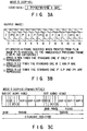
- FIG. 1A shows an example of the encoded data
- FIG. 1B shows the output image obtained by decoding the encoded data
- I indicates the video data encoded in a frame
- P the video data encoded by forward prediction
- B the video data encoded by bidirectional prediction.
- the components I, P, B, P and B of the video data are encoded repeatedly in the order they are mentioned.
- the length of the encoded data differs, from frame to frame.
- reproducing only I provides a sextuple-speed image
- reproducing I and P generates a double-speed image.
- the actual multiple speed is limited by the speed at which the data is read from a disk.
- This format is suitable for high-speed transfer rate, a large recording capacity, and semi-random access.
- six frames form a GOP
- five GOPs form a packet. It takes one second to reproduce this packet from the disk.
- the actual length of recorded signals on the disk differs from packet to packet, since the signals are encoded by moving-picture compression techniques.
- the minimum memory capacity required is only 24K bytes.
- the primary data item and the data rate for each data unit to be recorded on the disk are as follows:
- the expansion data contains a header and sub-video data.
- the sub-video data can be used as, for example, subtitle data used in a movie.
- the header is individual management information in the data unit and contains image-speech synchronizing data.
- the sub-video data is updated in units of GOPs containing the corresponding main image.
- the image and speech are also synchronized in units of GOPs, and the synchronization is corrected in units of GOPs, too.
- a plurality of channels may be provided for the sub-video data so that two types of sub-images can be output as an English scenario and a Japanese subtitles on a foreign film can.
- the allocated rate of the sub-video data is 64K bits/s, and if the recording time of one packet is 1.0 second, the buffer memory capacity for holding the sub-video data will be approximately 64K bits.
- the buffer memory capacity needed for two channels of sub-image may be 32K bits.
- Each data unit is read, in accordance with the data recorded in the management area. Since each data unit is processed independently of any other data unit, it can be easily edited and accessed.
- the image is decoded, beginning with the first frame (I picture) of the GOP.
- the speech is decoded, beginning with the speech frame specified by the image-speech synchronization.
- the image and the specified speech sample start to be outputted simultaneously.
- the length of speech frame is less than the length of 2048 samples of the original speech, and corresponds to 24 ms to 36 ms in terms of the duration of the original speech.
- the encoded data amount of the speech frame ranges from 288 bytes to 576 bytes.
- a frame ID is added to the header of each speech frame in each speech channel.
- the frame ID is made up of 24 bits, 4 bits of which represent a speech channel and 20 bits indicate a speech frame number.
- the approximately 1.0 second of audio data is usually as long as several tens of speech frames, though the length varies with the number of samples in a block and the sampling frequency.
- the image synchronization specifies the frame number of the encoded speech to which the decoded speech sample to be outputted with the timing of outputting the start frame of the corresponding GOP, and the speech sample number in the frame.
- FIGS. 2A to 2C show an another example of a moving-picture compression format
- FIGS. 3A to 3C still another example of a moving-picture format.
- the management information recorded in the management area will be explained below.
- the management data is recorded in the form of a table.
- each data unit consists of two or more GOPs.
- each data unit may contain only one GOP.
- the management table contains a volume identity field (VID) around the innermost track, a program information field (PIF) surrounding the VID, and a data unit allocation table (DAT) surrounding the PIF.
- VID is written, starting at the first byte in the management table area, and indicates information on various elements throughout the disk by using 256 bytes. For example, this information includes data as to whether the disk is for general recording or for reproduction only.
- PIF program information field
- various pieces of data on each program are recorded. For example, 16 bytes are used for each program.
- FIG. 5B shows an example of the contents of 16 bytes stored in the PIF.
- ATMB is the absolute time of the starting point of the present program in the volume.
- time code search each item of ATMB data is checked in the order of reproducing programs to find the number of the program in which a desired time code is present.
- Each DAT (to be described later) in the corresponding program is checked.
- the sum of the program time (PTMB, to be described later) and the ATMB is compared with the desired time code value to find the DAT to which the corresponding time code belongs.
- searching can be effected.
- the user can know the absolute starting time from the desired program and can, therefore, obtain a specific item of PIF data by searching for the ATMB corresponding to the absolute starting time.
- PINF indicates program attributes which are allocated to each program.
- program attributes are a copy disable flag (CPNH), a program type (PTYPE), a write attribute (PWRT), and the number of GOPs forming a data unit (SGDU).
- CPNH copy disable flag
- PTYPE program type
- PWRT write attribute
- SGDU number of GOPs forming a data unit
- the PIF also includes the parameters as shown in FIG. 5B, in which AINF identifies a speech encoding system, VINF denotes the identification of an image encoding system, ATRT represents the picture attributes (i.e., data for identifying the aspect ratio and a system such as the PAL or the NTSC system), and HRES and VRES indicate the data on horizontal resolution and vertical resolution, respectively.
- AINF identifies a speech encoding system
- VINF denotes the identification of an image encoding system
- ATRT represents the picture attributes (i.e., data for identifying the aspect ratio and a system such as the PAL or the NTSC system)
- HRES and VRES indicate the data on horizontal resolution and vertical resolution, respectively.
- PNTB indicates a start pointer that has a value indicating the DAT address (data unit number) at which the data unit at the program starting point is stored. Once the DAT address (data unit number) has been determined, it is possible to identify the position of the start sector of a program on the data area.
- PGML indicates the program number to be processed immediately after the current program is finished, when related programs are present. Namely, the order in which programs are produced does not necessarily coincide with the order of programs numbers. When the current program is the last program, there is no link destination and all bits of the PGML are "1".
- FIG. 5C shows the structure of the DAT.
- a zone number NZON
- NSTC sector number
- NTRC track number
- PTMB program time
- PNTL link pointer
- NZON is the zone number to which the recording sector at the start of the data unit belongs.
- the disk is divided in units of tracks in the radial direction, from the innermost circumference, and the zone numbers are allocated in sequence. Specifically, as shown in FIG. 4A, the data area has a reference position Rl on the disk and the number begins with 0 at this position.
- NSTC indicates a sector number in a zone. The sector number is not a serial number associated with another track or zone but a number complete only in the track or zone.
- NTRC indicates the number of the track in which the zone and the sector number (the header of the data unit) exist.
- PTMB is a flag representing the time position data on the video data (I picture) at the start of the data unit.
- the position data indicates a time (in seconds) elapsed from the program starting point.
- the time position data is used in searching for time codes explained earlier. Further, the time position data is taken in the reproducing apparatus, which uses it as the start reference data in order to display the program time, absolute time, remaining time, etc.
- PNTL is a flag showing a subsequent data unit immediately following the present DAT unit number in time.
- the unit corresponds to the data unit number.
- the effective value for the link pointer ranges from 0 ⁇ 0000 to 0 ⁇ FFFF.
- FIG. 4B graphically shows the management area and data area.
- the blocks in the data area each indicate programs.
- the DAT unit numbers are continuous in this order: 0 to Nmax.
- the first DAT unit number is determined by referring to the PNTB in the PIF. If the DAT unit number is 1, then the next link pointer will be 0.
- the link pointer of DAT unit number 0 is Nmax - 1.
- the link pointer of DAT unit number Nmax -1 is 2.
- FIG. 6A represents the address arrangement of the management table shown in FIG. 5A, particularly the address arrangement of the DAT.
- FIG. 6B shows another address arrangement which the management table may assume and in which fields not used are provided among the VID, the PIF and the DAT.
- an address offset will occur when the data search is switched from the VID to the PIF.
- the offset data is contained in the data recorded in the VID and will be recognized when a drive control MPU executes an address management program.
- the recording capacity of the management table will be calculated.
- the management table is frequently referred to. It takes much time to access to the table recorded on the disk.
- the management table may be mapped in the work RAM incorporated in the drive control MPU.
- the memory cost will be too much for the apparatus cost if the table is excessively large, and a great number of operations must be performed to convert the management table into desired parameters if the management table is not appropriately formulated. In view of this it is desirable to set the system of the apparatus in accordance with the apparatus cost and the amount of the table.
- FIG. 7 shows the encoder and decoder incorporated in a block diagram showing an apparatus for processing compressed video signals, which is a first embodiment of the invention.
- an original signal is input to an input terminal 100 and hence to signal separating means 101.
- the signal separating means 101 separates the original signal into audio data, video data, expansion data (e.g., subtitle data), a sync signal, and the like.
- the audio data is input to speech-data grouping means 102, the video data to image-data grouping means 103, the expansion data to expansion-data grouping means 104, and the sync signal to first system control means 110.
- the first system control means 110 controls the image-data grouping means 103 such that the means 103 forms groups of video data, each consisting of six frames, controls the speech-data grouping means 102 such that the means 102 forms groups of audio data in units of time of mode 1, and controls the expansion-data grouping means 104 such that the means 104 forms groups of expansion data which correspond to the frames.
- the groups of video data are input to image-data compressing means 106, which encodes and compresses the video data in the way explained with reference to FIGS. 1A, 1B and 1C.
- the groups of audio data are input to speech-data compressing means 105, which encodes and compresses the audio data.
- the groups of expansion data are input to expansion-data compressing means 107, which encodes and compresses the expansion data.
- the data output from the data compressing means 105, 106 and 107 are input to a formatter 108.
- the formatter 108 collects five GOPs (i.e., groups of encoded picture data items), thereby forming a data unit of the type shown in FIG. 1A.
- the data unit consists of encoded audio data, encoded expansion data and a header (i.e., additional data).
- Each data compressing means is controlled so as to generate encoded data the amount of which is an integral multiple of the maximum amount of data that can be recorded in one sector of a recording medium.
- Data units output from the formatter 108 are recorded on the recording medium or supplied to a data transfer system.
- the signals are read from the recording medium or transferred from the data transfer system and then supplied to signal separating means 121.
- the signal separating means 121 extracts the encoded audio data, the encoded video data, the encoded expansion data and the header from each data unit.
- the encoded audio data is supplied to a speech decoder 122, which decodes the data, thereby reproducing an audio signal.
- the encoded video data is supplied to an image decoder 123 and decoded.
- the encoded expansion data is supplied to an expansion data encoder 124 and decoded.
- the decoded video data and the decoded expansion data are supplied to data synthesizing means 125, which synthesises the video data and the expansion data, thereby reproducing a video signal.
- the data contained in the header is input to second system control means 126 and used to generate timing signals and to achieve image-speech synchronization and mode-setting.
- the apparatus shown in FIG. 7 is characterized by specific means of achieving image-speech synchronization.
- the data unit will be described again, in greater detail.
- the minimum memory capacity required is only 24K bytes.
- FIGS. 8A, 8B and 8C show the format of the encoded video data, the format of encoded audio data and the format of encoded additional data, respectively.
- the audio data has been encoded at a predetermined sampling frequency, and a prescribed number of sampled segments of data form a data block.
- a speech header is added to the data block, whereby the data block and the speech header constitute one frame.
- the speech header contains an frame ID which identifies the frame.
- the header of the data unit contains additional data.
- the additional data includes data representing the relationship between the encoded video data and the encoded audio data. More specifically, the encoded video data contains an image frame number as shown in FIG. 8A, and the encoded audio data contains an speech frame number as illustrated in FIG. 8B.
- the first frame of the first GOP0 is a specified picture 1 (SP1)
- the first frame of the second GOP1 is a specified picture 2 (SP2)
- SP5 a specified picture 5
- each of these specified pictures is an intraframe compressed data.
- the frames k-1, k+6, ... k+n of the encoded audio data correspond to SP1, SP2, ..., and SP5, respectively.
- the additional data also contains data representing the sampling numbers of the frames k-1, k+6, ... k+n. Therefore, the additional data indicates that SP1 corresponds to the frame k-1 of the audio data and has sampling number of #615, that SP2 corresponds to the frame k+6 of the audio data and has sampling number of #12, and that SP5 corresponds to the frame k+n of the audio data and has sampling number of #920.
- FIG. 9 illustrates the means for generating the additional data.
- An original video signal is supplied to a terminal 201.
- the video signal is quantized by quantizing means 202 and input to a frame memory 203.
- the video signals read from the frame memory 203 are input to image encoding means 204.
- the image encoding means 204 encodes the signals, generating video data pieces which correspond to frames.
- the video data is supplied to a formatter (not shown), which generates video data of the format shown in FIGS. 1A, 1B and 1C.
- a specified-picture frame pulse is supplied to an input terminal 205 and hence to the frame memory 203 and the image encoding means 204, serving as a write timing signal and a read timing signal for the frame memory 203 and also as a timing signal for the image encoding means 204.
- a program start pulse is supplied to an input terminal 206 and hence to a 1/6 frequency divider 207 and also to a speech frame pulse counter 214. This pulse clears the 1/6 frequency divider 207 which counts the image frame pulse, and generates a pulse for a specified-picture frame of the type shown in FIG. 8A.
- the speech frame pulse counter 214 starts counting speech-frame pulses.
- a speech-sampling pulse is supplied to an input terminal 208, and an original audio signal is supplied to an input terminal 209.
- the original audio signal is sampled and hence quantized by sampling/quantizing means 210.
- the output of the sampling/quantizing means 210 is input to speech encoding means 211 and encoded into audio data.
- the speech-frame number generated by the speech frame pulse counter 214 is added to the header of the audio data output from the speech encoding means 211.
- the speech-sampling pulse supplied to the input terminal 208 is input to an 1/N frequency divider 212 and converted into N speech frame pulses, so that each frame of audio data may be sampled with N sampling pulses.
- the speech frame pulses are supplied to the speech encoding means 211, which encodes the speech data in units of frames.
- the speech frame pulses are supplied, as clock pulses, to a speech-sampling pulse counter 213.
- Each speech frame pulse clears the speech-sampling pulse counter 213.
- the output of the speech-sampling pulse counter 213, which represents the number of samples extracted from one frame of audio data, is input to a register 215.
- the speech-frame number is also input to the register 215.
- the speech-frame number has been generated by clearing the speech frame pulse counter 214 by using a program start pulse and counting the speech frame pulses. Input to the register 215 are the speech-frame number and the number of speech samples. These data items are latched by a specified-picture frame pulse and subsequently output. The number of speech samples is cleared by a speech-frame pulse. Since the number of speech samples is latched by the specified-picture frame pulse while the number is increasing, the latched number of speech samples is used as a speech-sample number.
- the additional data output from the register 215 is used by the formatter 108 to generate a data unit of the type shown in FIG. 1A.
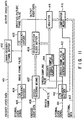
- FIG. 10 shows the means for reproducing the additional data, thereby to accomplish image-speech synchronization.
- the encoded video data, the encoded audio data, and the additional data are reproduced, unit by unit, from the recording medium (FIG. 7).
- the additional data defines the period during which the decoded video data and the decoded audio data are to be output.
- the encoded audio data read from the recording medium is input, unit by unit, to a speech buffer 302 via an input terminal 301 as shown in FIG. 10.
- the encoded video data read from the recording medium is input, unit by unit, to an image buffer 312 via an input terminal 311.
- the additional data is input to a shift register 322 through an input terminal 321.
- the encoded audio data is input to frame number extracting means 305, too.
- the encoded audio data output from the speech buffer 302 is input to speech decoding means 303 and decoded thereby in units of frames.
- the decoded audio data is input to a speech block buffer 304.
- the encoded video data output from the image buffer 312 is input to image decoding means 313 and decoded thereby in units of frames.
- the decoded video data is input to an image frame buffer 314. Blocks of decoded audio data are sequentially stored into the speech block buffer 304.
- the speech-frame number extracted by the frame number extracting means 305 is input to comparator means 323, which compares the speech-frame number with the speech-frame number extracted from the header of the encoded audio data. If the numbers compared are identical, the comparator means 323 generates a coincidence pulse, which is supplied to gate means 324. Then, the sample number contained in the additional data is output through gate means 324 to the preset input of an address counter 325.
- the sample number supplied to the address counter 325 designates that location in the speech block buffer 304 from which the decoded audio data is to be read.
- the coincidence pulse from the comparator means 323 is supplied to speech-sampling pulse generating means 326 and image frame pulse generating means 327. In response to the coincidence pulse, both pulse generating means 326 and 327 start performing their functions, whereby the audio data is output in synchronism with the video data, in accordance with the corresponding sample number whose relationship with the video data designated by the additional data.
- the video data supplied to the image decoding means 313 and hence to the image frame buffer 314 is processed into decoded picture data of SP2.
- This synchronization is performed by an adjusting means 328.
- the audio data is output in synchronism with the picture data of SP2 et seq.
- the adjusting means 326 recognizes the image frame number, too, by using the output of the image decoding means 313.
- Neither the video data nor the audio data, or only the video data, may be output until the comparator means 323 generates a coincidence signal. Once the means 323 has generated a coincidence signal, the comparator means 323 may be stopped, since the speech in a group of pictures is synchronous with the image in the same group of pictures. The comparator means may be periodically driven, each time in response to a specified-picture signal.
- the timing of outputting video data from the image frame buffer 314 and the timing of outputting the audio data from the speech block buffer 304 are controlled for the purpose of synchronizing any specified-picture frame and a designated speech sample.
- additional means may be used to adjust the time for storing decoded data into a buffer memory (not shown) or the time for storing encoded data into a buffer memory (not shown).
- FIG. 11 shows another type of means for reproducing the additional data, thereby to accomplish image-speech synchronization.
- encoded video data is supplied to an input terminal 401 and decoded by an image decoder/frame buffer 402.
- An internal clock signal is supplied to an input terminal 403 and is frequency-divided by an 1/M frequency divider 404 into image frame pulses.
- image frame pulses are supplied as timing signals to the image decoder/frame buffer 402. They are supplied also to a 1/6 frequency divider 405 and frequency-divided into specified-picture frame pulses which are synchronous with the specified-picture signals shown in FIG. 8A.
- Encoded audio data is input via an input terminal 406 to speech decoding means 407 and is decoded thereby.
- the decoded audio data is input to a decoded speech block buffer 408.
- An internal clock signal is supplied through an input terminal 411 to an 1/N frequency divider 412 and frequency-divided into speech-sampling pulses.
- the speech-sampling pulses are input to speech-frame pulse generating means 413 and also to a decoded speech-sample address counter 414.
- the pulse generating means 413 generates speech frame pulses corresponding to speech frames.
- the speech frame pulses are supplied, as timing signals, to the speech decoding means 407 and the decoded speech-sample address counter 414.
- the decoded speech-sample address counter 414 is reset by a speech frame pulse and counts speech-sampling pulses. Hence, the output of the address counter 414 represents a speech sample number.
- the speech sample number is used as a read address for the decoded speech block buffer 408, and is input to a register 415.
- the register 415 latches the speech sample number in response to a specified-picture frame pulse.
- the speech sample number, thus latched, is input to comparator means 416.
- the comparator means 416 compares the speech sample number with the speech sample number contained in the additional data supplied from an input terminal 417.
- the comparator means 416 supplies a divider-adjusting signal to the 1/N frequency divider 412, thereby controlling the phase of the speech-sampling pulses and that of the speech frame pulses.
- the divider (N) of the 1/N frequency-divider is increased or decreased by 1 to 2.
- the divider (M) of the 1/M frequency divider 404 may be adjusted in order to render the video data and the audio data synchronous.
- the dividers of both frequency dividers 404 and 412 may be adjusted for the same purpose. No matter whether either the divider (M) or the divider (N), or both, are adjusted, the video data and the audio data can be synchronized before they become excessively asynchronous, despite that the frequency of the encoding clock signal differs, though slightly, from the frequency of the decoding clock signal.
- the present invention is not limited to the embodiment described above.
- FIG. 12 shows a recording/reproducing apparatus which is a second embodiment of the present invention.
- the reproduction system of this apparatus will be described below.
- a disk 10 is placed on a turntable 501, which is rotated by a motor 502.
- a pickup means 503 reads the data recorded on the disk 10.
- the pickup means 503 is moved to a desired track of the disk 10 under the control of a driving section 504.
- An output of the pickup means 103 is supplied to a modulation and demodulation section 601, which demodulates the supplied signal.
- the demodulated data is supplied to an error correction data processing section 602, which corrects errors and supplies the resulting signal to a data string processing section 603.
- the data string processing section 603 extracts video data, subtitle and character data, and audio data.
- the subtitle and character data and audio data are recorded so as to correspond to the video data, as explained later.
- various languages can be selected for the subtitle and character data and audio data.
- the selection is made under the control of a system control section 604.
- the user supplies the input from an operator section 605 to the system control section 604.
- the data string processing section 603, the system control section 604, and the operator section 605 in the reproducing apparatus constitute data string control means and scene select means, in accordance with the user's operating of the operator section 605.
- the video data separated at the data string processing section 603 is supplied to a video processing section 606, which carries out a decode process according to the type of display unit. For example, the video data is converted into a suitable form for an NTSC, PAL, SECAM, or wide screen.
- the video signal decoded at the video processing section 606 is supplied to an adder 608, which adds it with the subtitle and character data and supplies the addition result at an output terminal 609.
- the audio data separated at the data string processing section 603 is supplied to an audio processing section 611, which demodulates it and supplies the demodulated signal at an output terminal 612.
- the audio processing section acting as a decoding section which contains an audio processing section 613 in addition to the audio processing section 611, can also reproduce speech in another language and supply this reproduced signal at an output terminal 614.
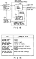
- FIG. 13 illustrates the data string processing section 603 (FIG. 12) in more detail.
- the data string processing section 603 is designed to analyze the header (also known as "subcode") of each data unit, to separate the packets contained in the data unit, and to supply the packets to the respective decoders.
- FIG. 14 shows the various types of data which are contained in the header of each data unit.
- the DUT header contains program number, program time, data-unit size, the starting position of video data, the starting position of audio data, image-speech synchronization data, the starting position of sub-video data, and the like.
- the program number i.e., the number assigned to the program
- the program time i.e., the time required to process the data unit of the program
- the size of the data unit is represented in the number of bytes which forms it.
- the starting position of the video data is indicated by the ordinal number of the first byte of the video data, counted from the starting byte of the data unit.
- the image-speech synchronization data consists of the frame number and sample number of the audio data which corresponds to a specified picture frame.
- the starting position of the sub-video data is indicated by the ordinal number of the first byte of the sub-video data, counted from the starting byte of the data unit.
- Three identical sets, each comprised of data-unit size, starting position of video data, starting position of audio data, image-speech synchronization data, are recorded so that, in case one or two set cannot be read or the disk has been damaged, the remaining set or sets may be read from the disk.
- the symbol "x 3" shows that this safety measure has been taken.
- the data string processing section 603 comprises a DUT header analyzing section 701 and a data cache memory 702.
- the section 701 analyzes the DUT header.
- the data unit is stored into the data cache memory 702.
- the section 701 can determine what kind of data is stored at which address in the data cache memory 702. It can therefore set a read address for the video data so that the video data (actually a GOP) may be read from the memory 702, separately from the other component of the data unit.
- the encoded audio data is read from the memory 702, also separately from the other component of the data unit. To read the audio data, it is necessary to supply a channel-designating address data to the data cache memory 702 from the system control section 604, since there are provided a plurality of channels.
- the encoded expansion data is read from the data cache memory 702 in a similar manner.
- each data unit is formed of a header portion, an expansion data portion, an encoded audio data portion and an encoded video data portion, and the header portion contains data-unit size, the starting position of video data, the starting position of audio data, the staring position of expansion data, image-speech synchronization data, and the like.
- the DUT header analyzing section 701 analyzes the header portion and determines what kind of data is stored at which address in the data cache memory 702, thereby setting a read address for the video data so that any encoded data may be supplied from the memory 702 to the decoder, separately from the other component of the data unit.
- the information area of the disk 10 has a management area on the inner side and a data area outside the management area, for example.
- management information needed to access the data in the data area is recorded as explained later.
- data area information including a header, sub-video data, audio data, and video data is recorded.
- the identical contents of management information are recorded in the section (Pl to P2) of the innermost two and half tracks and the next two-and-half track section (P2 to P3). That is, the start positions of the identical contents of management information are set on radiating lines with different angles on the disk 10. In this embodiment, the angle that two radiating lines make is 180 degrees.
- Two sets of management information are recorded on the disk 10. Hence, if one of them cannot be read from the disk due to dirt, the other set of management information can be used. This prevents the important information from being lost in accessing the data area.
- the two sets of management information are recorded in different positions on the disk.
- the management information cannot be read, it is particularly fatal to the reproduction of data from the disk.
- the start position of each item of information is set on a different radial line.
- the recording start positions differ from each other by an angle of 180 degrees. The angular difference is not restricted to this. For instance, it may be 90 or other degrees. While in the embodiment, two sets of the same data are recorded, three or four sets of the same data may be recorded.
- FIG. 16 is an enlarged view of the contents of data unit DUT #0 in the data area.
- data unit DUT #0 there is a subcode (SUB-CODE) at the start, followed by a sub-picture (SUB-PICTURE), audio data (AUDIO), video data (VIDEO) in that order.
- the subcode (SUB-CODE) contains the attributes of data unit DUT #0 and control data on the data unit.
- the sub-picture (SUB-PICTURE) contains subtitle data (for movie video) or character data (for kara-OK video and educational video), for example.
- the subtitle data and the character data are each given PICTURE #0 to #7, all of which or some of which differ from each other in language and the rest contain no signals.
- the audio (AUDIO) data is recorded in up to eight different languages AUDIO #0 through #7 (each reproduction lasts approximately one second). Each piece of audio data is recorded in frames, each frame, #0, #1, and so on being composed of headers (HEADERs) and data (DATA).
- the video data (VIDEO) contains 30 frames of images (approximately one second of reproduction), for example.
- the video (VIDEO) formation is recorded by high-efficient image encoding compression techniques. The number of frames is not limited by standards.
- the management information is stored in the form of a table.
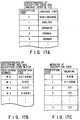
- a table of language codes is recorded in the VID, showing what language is recorded in which data area.
- the language code correspond to description codes 0, 1, ..., 8.
- the description code 0 corresponds to non-language, or background sound and music (B & M)
- the description codes 1, 2, 3, and 4 correspond to English, Japanese, French, and German, respectively.
- the correspondence between each description code and each language code is known when the VID is read at the start of the reproducing apparatus.
- bit data strings are defined in the PIF table.
- description codes correspond to data string numbers #0 through #7 on the disk (FIG. 17B).
- a description code is determined and the language code corresponding to the description code is also determined.
- the reproducing apparatus when the reproducing apparatus reads the data in the PIF table, it displays the first menu screen in accordance with data string numbers #0 to #7 (a display by the key display signal).
- This display is effected by, for example, supplying a language code to a conversion table to generate the display data corresponding to each language code. To supply the code of a language the user can understand, the user only needs to select and input the corresponding data string number by operating the operator section.
- the description code 1 is displayed.
- Dl i.e., English
- D2 Japanese
- Japanese Japanese
- a producer's comment is displayed in the language selected.
- the data address at which the comment information is recorded is recorded in, for example, the VID table.
- the comment data is displayed in the language the user can understand. For example, it is displayed on the second menu screen, in the language which the user has selected at the first menu screen. If the user has selected #2 at the first menu screen, comments is displayed in Japanese.
- the comments include a greeting from the producer, the date of production, the intention of the product, and the program time in the case of movies, for example. Seeing these comments displayed, the user can select an output mode for speech and subtitles, by pushing the speech and subtitle change button provided at the operator section. When the user pushes the speech change button, a cursor appears on the screen.
- the cursor moves from one item to another in the language column, from non-language to Japanese, English, French, German, and son on, in the language column.
- the desired item is selected unless the button is pushed during that predetermined time.
- the subtitle change button is similarly operated, to select the subtile in the desired language.
- the reproduction mode in the speech selected at the first menu screen will be effected.
- the speech output mode and the subtitle display mode can be changed during operation of the reproducing apparatus.
- the system control section of the reproducing apparatus controls the pickup-driving section.
- the pickup-driving section moves the pickup, which reads the selected program from the disk.
- the management information is extremely important in accessing to the disk. If the management information not be read, it would be fatal to the reproduction of data from the disk.
- FIG. 18 is a flow chart explaining how the data string processing section 603 processes the signals supplied to it via the error correction data processing section 602.
- the section 603 receives the data supplied from the section 602 and determines whether or not the data contains errors.
- the first management information is read from the disk (Steps S11 and S12). Then, the data string processing section 603 determines whether or not the information contains errors (Step S13). If NO, the information is stored as a management table into the work memory incorporated in the system control section 604 (Step S20). If YES, the section 603 determines whether or not the errors can be corrected, for example by counting the number of the errors (Step S14). If YES in Step S14, the errors are corrected (Step S19). The information, thus corrected, is stored as a management table into the work memory. If NO in Step S14, the second management information is read from the disk (Step 15).
- Step S16 determines whether or not the information contains errors. If NO in Step 16, the information is stored as a management table into the work memory incorporated in the system control section 604 (Step S20). If YES in Step S16, the section 603 determines whether or not the errors can be corrected, for example by counting the number of the errors (Step S17). If YES in Step S17, the errors are corrected (Step S19). The data, thus corrected, is stored as a management table into the work memory. IF NO in Step S17, a warning is displayed (Step 18).
- the embodiment described above it is determined whether the first management information is valid or invalid. If the first management information is invalid, the second management information is read from the disk. Instead, both the first management information and the second management information may be read from the disk and simultaneously be examined for errors. In this case, if errors are found in a part of one of the management information items, that part is automatically replaced by the corresponding part of the other management information, thereby removing errors, and the error-free management information is stored into the work memory.
- the reproducing apparatus and the disk both according to the present invention, can minimizing the possibility that important information to be used in the apparatus is destroyed completely when the disk is damaged.
Abstract
Description
- The present invention relates to a recording medium such as a writable and readable magnetic disk or a writable and readable optical disk, and also to an apparatus for processing compressed video signals, which can effectively operate in a recording/reproducing apparatus using a magnetic disk, an optikal disk or a CD-ROM as a recording medium.
- In recent years, magnetic disks and optikal disks have been used in various information systems as recording media for storing a great amount of data. A number of programs can now be stored on such a disk thanks to the recent progress in the technology of code-compressing video data at a high ratio. Various systems for compresing moving picture data are known. One example is the system which is defined in ISO-11172 (MPEG).
- To record more data on a disk, it is desirable not only to record signals which have been generated by compression-coding or variable-length coding by means of the moving-picture compression, but also to increase the recording density of the data-recording region of a disk. There is a demand for techniques of searching data at high speed and reproducing the same from the disk in a special manner. When a video signal is coded by moving-picture compression, the video signal and an audio signal related to the video signal must be synchronized.
- If a disk is stained with dirt, a reproducing apparatus will not be able to red the important information from the disk. Once a table of information for managing the programs recorded on the disk has been destroyed, the apparatus can no longer reproduce the important information from the disk.
- The object of the present invention is to provide a recording medium which can more efficiently store data of different types (like main image data/video data, sub-picture data, audio data).
- Another aspect of the present invention is to provide a recording medium (disk) which can minimize the possibility that important information to be used in a reproducing apparatus is destroyed completely when the disk is damaged.
- According to the present invention there is provided a recording medium comprising program data stored in one area; and management information stored in another area and used for managing the program data, wherein said program data includes: a packet of encoded main image data (VIDEO) which is obtained by compressing and encoding main image data and is divisible in units of one frame; and a packet of encoded sub-image data (SUB-PICTURE) which is independent of the main image data, is selectively superimposable on the main image data, and is data compressed and encoded by means of a system independent of a system used for encoding the main image data.
- Preferred embodiments of the disk are defined in the subclaims.
- According to another aspect of the invention, there is provided a disk structure having a management area on a central portion and a data area surrounding the management areas, wherein identical management data items are recorded in the management areas, data to be accessed based on the management data item is recorded in the data area, and starting positions of the identical management data items are set on different radial lines spaced apart by different angles.
- This invention can be more fully understood from the following detailed description when taken in conjunction with the accompanying drawings, in which:
- FIG. 1A is a diagram schematically representing code data generated in a first embodiment of the invention;
- FIG. 1B is a diagram schematically showing an output image obtained by decoding the coded data shown in FIG. 1A;
- FIG. 1C is a diagram illustrating the format of compressed signals generated in the first embodiment of the invention;
- FIG. 2A is a diagram schematically representing code data generated in second embodiment of the invention;
- FIG. 2B is a diagram schematically showing an output image obtained by decoding the coded data shown in FIG. 2A;
- FIG. 2C is a diagram illustrating the format of compressed signals generated in the second embodiment of the invention;
- FIG. 3A is a diagram schematically representing code data generated in a third embodiment of the invention;
- FIG. 3B is a diagram schematically showing an output image obtained by decoding the coded data shown in FIG. 3A;
- FIG. 3C is a diagram illustrating the format of compressed signals generated in the third embodiment of the invention;
- FIG. 4A is a diagram showing the management area and data area of a disk according to the present invention;
- FIG. 4B shows the data unit allocation table (DAT) on the disk shown in FIG. 4A;
- FIG. 5A shows the management table recorded in the management area of the disk;
- FIG. 5B is a table showing the contents of 16 bytes in the program information field (PIF) on the disk;
- FIG. 5C is a table showing the structure of the DAT;
- FIG. 6A is a diagram representing the address arrangement of the management table shown in FIG. 5A, particularly the address arrangement of the DAT;
- FIG. 6B is a diagram showing an example address arrangement which the management table may assume;
- FIG. 7 is a block diagram showing the first embodiment of the invention;
- FIG. 8A is a diagram showing the format of encoded video data;
- FIG. 8B is a diagram representing the format of encoded audio data;
- FIG. 8C is a diagram showing the format of encoded additional data;
- FIG. 9 is a block diagram showing an example of the encoder incorporated in the system for processing the data units shown in FIGS. 8A, 8B and 8C;
- FIG. 10 is a block diagram showing an example of the decoder incorporated in the system for processing the data units shown in FIGS. 8A, 8B and 8C;
- FIG. 11 is a block diagram showing another example of the decoder incorporated in the system for processing the data units shown in FIGS. 8A, 8B and 8C;
- FIG. 12 is a block diagram illustrating a recording/reproducing apparatus which is a second embodiment of the present invention;
- FIG. 13 is a block diagram showing the data-string processing section of the apparatus shown in FIG. 12;
- FIG. 14 is a table showing the structure of the header section of a data unit;
- FIG. 15A is a perspective view of the disk according to the present invention;
- FIG. 15B is a diagram illustrating the spiral track formed on the disk;
- FIG. 16 is a diagram showing the contents of data
unit DUT # 0 recorded in the data area of the disk; - FIG. 17A illustrates the table recorded in the volume identity field (VID) on the disk and showing the correspondence between description codes and language codes;
- FIG. 17B shows the table recorded in the PIF on the disk;
- FIG. 17C is a table showing the meaning of each description code; and
- FIG. 18 is a flow chart explaining the operation of the data-string processing section of the apparatus shown in FIG. 12.
- The present invention will now be described, with reference to the accompanying drawings.
- The moving-picture compression format used in the present invention will be first explained. To encode video data, groups of pictures (GOPs) are combined, forming a packet, and audio data (for approximately 1.0 second) and expansion data, both for the packet, are encoded. The data thus encoded is added to the compressed video data, forming a data unit. Each GOP is fixed in the same program. A speech synchronizing time code is arranged as the header (i.e., the first part of the data unit), and sub-video data is arranged next to the header.
- FIG. 1A shows an example of the encoded data, and FIG. 1B shows the output image obtained by decoding the encoded data. In FIGS. 1A and 1B, I indicates the video data encoded in a frame, P the video data encoded by forward prediction, and B the video data encoded by bidirectional prediction. In this mode, the components I, P, B, P and B of the video data are encoded repeatedly in the order they are mentioned. As a result, the length of the encoded data differs, from frame to frame. With such a format, reproducing only I provides a sextuple-speed image, and reproducing I and P generates a double-speed image. The actual multiple speed is limited by the speed at which the data is read from a disk. This format is suitable for high-speed transfer rate, a large recording capacity, and semi-random access. In this example, as shown in FIG. 1C, six frames form a GOP, and five GOPs form a packet. It takes one second to reproduce this packet from the disk. The actual length of recorded signals on the disk differs from packet to packet, since the signals are encoded by moving-picture compression techniques.
- Therefore, a packet consists of 30 frames (= 5 GOPs × 6 frames/GOP). Each set of 30 frames of audio data is recorded in 48K bytes (= 4 ch × 12 K bytes/s). In the case where two channels are used simultaneously, the minimum memory capacity required is only 24K bytes.
- The primary data item and the data rate for each data unit to be recorded on the disk are as follows:
- Expansion data = 128K bits/s = 16K bytes/s
- Audio data = 384K bits/s = 48K bytes/s
- Image data = 4096K bits/s = 512K bytes/s
- The expansion data contains a header and sub-video data. The sub-video data can be used as, for example, subtitle data used in a movie. The header is individual management information in the data unit and contains image-speech synchronizing data. The sub-video data is updated in units of GOPs containing the corresponding main image. The image and speech are also synchronized in units of GOPs, and the synchronization is corrected in units of GOPs, too.
- For subtitle data, a plurality of channels may be provided for the sub-video data so that two types of sub-images can be output as an English scenario and a Japanese subtitles on a foreign film can. If the allocated rate of the sub-video data is 64K bits/s, and if the recording time of one packet is 1.0 second, the buffer memory capacity for holding the sub-video data will be approximately 64K bits. The buffer memory capacity needed for two channels of sub-image may be 32K bits.
- Once the video data, the audio data, and the expansion data have been encoded, they are completed within the data unit and are totally independent from other data units.
- On the disk there is provided a management area. Each data unit is read, in accordance with the data recorded in the management area. Since each data unit is processed independently of any other data unit, it can be easily edited and accessed.
- The relationship between the data area and the associated management information will be described.
- In the actual layout, a byte align process is performed for each GOP, and a sector align process is always carried out for each data unit to make it easy to segment the data unit. Due to the sector align process performed, the actual recording capacity of the disk is reduced. In the case where the display frame rate is 30 frame/sec, each GOP consists of six pictures (frames), and each data unit consists of five GOPs, sector align process is performed for every data which corresponds to 1.0 second of a program. Therefore, a disk recording a 120-minute program has its recording capacity reduced by 7200 sectors. This reduction is 0.2% for a disk whose total recording capacity is 346,752 sectors each capable of storing 1 KB of data.
- In a reproducing operation, the image is decoded, beginning with the first frame (I picture) of the GOP. The speech is decoded, beginning with the speech frame specified by the image-speech synchronization. At the time when the decoding of both of the specified speech frame and the start frame of the image GOP has been completed, the image and the specified speech sample start to be outputted simultaneously.
- For audio data, approximately 1.0 second of encoded audio data is inserted in the data unit. After a certain number of samples are grouped into a block, with the adjacent block edges tucked in a bit, the speech is encoded in units of this number of samples, and a header is added to the encoded speech thereby to form an encoded speech frame.
- The length of speech frame is less than the length of 2048 samples of the original speech, and corresponds to 24 ms to 36 ms in terms of the duration of the original speech. The encoded data amount of the speech frame ranges from 288 bytes to 576 bytes. A frame ID is added to the header of each speech frame in each speech channel. The frame ID is made up of 24 bits, 4 bits of which represent a speech channel and 20 bits indicate a speech frame number. The approximately 1.0 second of audio data is usually as long as several tens of speech frames, though the length varies with the number of samples in a block and the sampling frequency. The image synchronization specifies the frame number of the encoded speech to which the decoded speech sample to be outputted with the timing of outputting the start frame of the corresponding GOP, and the speech sample number in the frame. The time code consists of 32 bits, 20 bits of which represent a speech frame number and the remaining 12 bits of which specify a speech sample number. This enables the maximum error in the speech and image synchronization in the entire system to coincide with half the sampling period of speech. When fs = 32 KHz, the maximum speech synchronization error is approximately 16 us.
- FIGS. 2A to 2C show an another example of a moving-picture compression format, and FIGS. 3A to 3C still another example of a moving-picture format.
- The management information recorded in the management area will be explained below. The management data is recorded in the form of a table.
- In the embodiments described above, each data unit consists of two or more GOPs. Instead, according to the present invention, each data unit may contain only one GOP.
- As shown in FIG. 4A, the management table contains a volume identity field (VID) around the innermost track, a program information field (PIF) surrounding the VID, and a data unit allocation table (DAT) surrounding the PIF. The VID is written, starting at the first byte in the management table area, and indicates information on various elements throughout the disk by using 256 bytes. For example, this information includes data as to whether the disk is for general recording or for reproduction only. In the program information field (PIF), various pieces of data on each program are recorded. For example, 16 bytes are used for each program.
- FIG. 5B shows an example of the contents of 16 bytes stored in the PIF.
- ATMB is the absolute time of the starting point of the present program in the volume. In the case of time code search, each item of ATMB data is checked in the order of reproducing programs to find the number of the program in which a desired time code is present. Each DAT (to be described later) in the corresponding program is checked. Then, the sum of the program time (PTMB, to be described later) and the ATMB is compared with the desired time code value to find the DAT to which the corresponding time code belongs. In this procedure, searching can be effected. By the method based on the absolute starting time, the user can know the absolute starting time from the desired program and can, therefore, obtain a specific item of PIF data by searching for the ATMB corresponding to the absolute starting time.
- PINF indicates program attributes which are allocated to each program. Among the program attributes are a copy disable flag (CPNH), a program type (PTYPE), a write attribute (PWRT), and the number of GOPs forming a data unit (SGDU). If the CPNH is set at 1, it means copy disable and if it is set at 0, it means copy enable. The PTYPE, which consists of three bits, indicates such types as the home video, movie, music, kara-OK, computer graphics, interactive use, game, computer data, or program. When the PWRT has a value of 1, it means write enable.
- The PIF also includes the parameters as shown in FIG. 5B, in which AINF identifies a speech encoding system, VINF denotes the identification of an image encoding system, ATRT represents the picture attributes (i.e., data for identifying the aspect ratio and a system such as the PAL or the NTSC system), and HRES and VRES indicate the data on horizontal resolution and vertical resolution, respectively.
- PNTB indicates a start pointer that has a value indicating the DAT address (data unit number) at which the data unit at the program starting point is stored. Once the DAT address (data unit number) has been determined, it is possible to identify the position of the start sector of a program on the data area.
- PGML indicates the program number to be processed immediately after the current program is finished, when related programs are present. Namely, the order in which programs are produced does not necessarily coincide with the order of programs numbers. When the current program is the last program, there is no link destination and all bits of the PGML are "1".
- FIG. 5C shows the structure of the DAT. In this table, there are such parameters as a zone number (NZON), a sector number (NSTC), and a track number (NTRC) on a disk, as well as a program time (PTMB), and a link pointer (PNTL).
- NZON is the zone number to which the recording sector at the start of the data unit belongs. The disk is divided in units of tracks in the radial direction, from the innermost circumference, and the zone numbers are allocated in sequence. Specifically, as shown in FIG. 4A, the data area has a reference position Rl on the disk and the number begins with 0 at this position. NSTC indicates a sector number in a zone. The sector number is not a serial number associated with another track or zone but a number complete only in the track or zone. NTRC indicates the number of the track in which the zone and the sector number (the header of the data unit) exist. PTMB is a flag representing the time position data on the video data (I picture) at the start of the data unit. The position data indicates a time (in seconds) elapsed from the program starting point. The time position data is used in searching for time codes explained earlier. Further, the time position data is taken in the reproducing apparatus, which uses it as the start reference data in order to display the program time, absolute time, remaining time, etc.
- PNTL is a flag showing a subsequent data unit immediately following the present DAT unit number in time. The unit corresponds to the data unit number. When there is no link destination at the program end, all bits are set at 1 (= 0 × FFFF). The effective value for the link pointer ranges from 0 × 0000 to 0 × FFFF.
- FIG. 4B graphically shows the management area and data area. The blocks in the data area each indicate programs. The DAT unit numbers are continuous in this order: 0 to Nmax. The first DAT unit number is determined by referring to the PNTB in the PIF. If the DAT unit number is 1, then the next link pointer will be 0. The link pointer of
DAT unit number 0 is Nmax - 1. The link pointer of DAT unit number Nmax -1 is 2. By checking for the zone number, the sector number, and the track number according to the change of the DAT unit number, it is possible to obtain data on the reproduction order such astrack 4 insector 3 inzone 1,track 7 insector 2 inzone 0, andtrack 10 insector 30 inzone 3. - FIG. 6A represents the address arrangement of the management table shown in FIG. 5A, particularly the address arrangement of the DAT.
- FIG. 6B shows another address arrangement which the management table may assume and in which fields not used are provided among the VID, the PIF and the DAT. In the address arrangement of FIG. 6B, an address offset will occur when the data search is switched from the VID to the PIF. The offset data is contained in the data recorded in the VID and will be recognized when a drive control MPU executes an address management program.
- The recording capacity of the management table will be calculated.
- The capacity for recording the management table depends on the number of programs and the number of data units which are recorded on the disk. Assuming that 256 programs and 7200 data units (1 sec/unit, corresponding to 2 hours), the data for the management table amounts to 61952 bytes (= 256 + (16 × 256) + (8 × 7200). Namely, in a system wherein a data unit corresponds to about 1 second, management information for 2 hours can be recorded in a 63KB memory. In other words, a 63KB memory is practically sufficient for storing the entire management table.
- The physical position of the start sector of the management table is usually defined by ZONE = 0, TRACK = 0 and SECTOR = 0. To protect data, a plurality of management tables may be recorded in different physical regions. The management table is frequently referred to. It takes much time to access to the table recorded on the disk. To reduce the access time, the management table may be mapped in the work RAM incorporated in the drive control MPU. However, the memory cost will be too much for the apparatus cost if the table is excessively large, and a great number of operations must be performed to convert the management table into desired parameters if the management table is not appropriately formulated. In view of this it is desirable to set the system of the apparatus in accordance with the apparatus cost and the amount of the table.
- FIG. 7 shows the encoder and decoder incorporated in a block diagram showing an apparatus for processing compressed video signals, which is a first embodiment of the invention. In operation, an original signal is input to an input terminal 100 and hence to signal separating means 101. The signal separating means 101 separates the original signal into audio data, video data, expansion data (e.g., subtitle data), a sync signal, and the like. The audio data is input to speech-data grouping means 102, the video data to image-data grouping means 103, the expansion data to expansion-data grouping means 104, and the sync signal to first system control means 110. While being set in
mode 1, the first system control means 110 controls the image-data grouping means 103 such that themeans 103 forms groups of video data, each consisting of six frames, controls the speech-data grouping means 102 such that themeans 102 forms groups of audio data in units of time ofmode 1, and controls the expansion-data grouping means 104 such that themeans 104 forms groups of expansion data which correspond to the frames. The groups of video data are input to image-data compressing means 106, which encodes and compresses the video data in the way explained with reference to FIGS. 1A, 1B and 1C. The groups of audio data are input to speech-data compressing means 105, which encodes and compresses the audio data. The groups of expansion data are input to expansion-data compressing means 107, which encodes and compresses the expansion data. The data output from the data compressing means 105, 106 and 107 are input to a formatter 108. The formatter 108 collects five GOPs (i.e., groups of encoded picture data items), thereby forming a data unit of the type shown in FIG. 1A. The data unit consists of encoded audio data, encoded expansion data and a header (i.e., additional data). Each data compressing means is controlled so as to generate encoded data the amount of which is an integral multiple of the maximum amount of data that can be recorded in one sector of a recording medium. - Data units output from the formatter 108 are recorded on the recording medium or supplied to a data transfer system. The signals are read from the recording medium or transferred from the data transfer system and then supplied to signal separating means 121. The signal separating means 121 extracts the encoded audio data, the encoded video data, the encoded expansion data and the header from each data unit. The encoded audio data is supplied to a
speech decoder 122, which decodes the data, thereby reproducing an audio signal. The encoded video data is supplied to animage decoder 123 and decoded. The encoded expansion data is supplied to anexpansion data encoder 124 and decoded. The decoded video data and the decoded expansion data are supplied to data synthesizing means 125, which synthesises the video data and the expansion data, thereby reproducing a video signal. The data contained in the header is input to second system control means 126 and used to generate timing signals and to achieve image-speech synchronization and mode-setting. - The apparatus shown in FIG. 7 is characterized by specific means of achieving image-speech synchronization.
- The data unit will be described again, in greater detail.
- As has been described above, one packet of video data consists of 30 frames (= 5 GOPs × 6 frames/GOP), and 30 frames of audio data, forming one set, are recorded in 48K bytes (= 4 ch × 12 K bytes/s), while the apparatus is being set in
mode 1. When two channels are used simultaneously, the minimum memory capacity required is only 24K bytes. - FIGS. 8A, 8B and 8C show the format of the encoded video data, the format of encoded audio data and the format of encoded additional data, respectively. The audio data has been encoded at a predetermined sampling frequency, and a prescribed number of sampled segments of data form a data block. A speech header is added to the data block, whereby the data block and the speech header constitute one frame. The speech header contains an frame ID which identifies the frame.
- The header of the data unit contains additional data. The additional data includes data representing the relationship between the encoded video data and the encoded audio data. More specifically, the encoded video data contains an image frame number as shown in FIG. 8A, and the encoded audio data contains an speech frame number as illustrated in FIG. 8B. As shown in FIG. 8A, the first frame of the first GOP0 is a specified picture 1 (SP1), the first frame of the second GOP1 is a specified picture 2 (SP2), and so forth. The first frame of the last GOP4 is a specified picture 5 (SP5). (Each of these specified pictures is an intraframe compressed data.) The frames k-1, k+6, ... k+n of the encoded audio data correspond to SP1, SP2, ..., and SP5, respectively. Data showing this relation between the SPs of the encoded video data, on the one hand, and the frames k-1, k+6, ... k+n of the encoded audio data, on the other hand, is contained in the addition data, as can be understood from FIG. 8C. The additional data also contains data representing the sampling numbers of the frames k-1, k+6, ... k+n. Therefore, the additional data indicates that SP1 corresponds to the frame k-1 of the audio data and has sampling number of #615, that SP2 corresponds to the frame k+6 of the audio data and has sampling number of #12, and that SP5 corresponds to the frame k+n of the audio data and has sampling number of #920.
- The means for generating the additional data will be described below, with reference to FIG. 9.
- FIG. 9 illustrates the means for generating the additional data. An original video signal is supplied to a terminal 201. The video signal is quantized by quantizing means 202 and input to a
frame memory 203. The video signals read from theframe memory 203 are input to image encoding means 204. The image encoding means 204 encodes the signals, generating video data pieces which correspond to frames. The video data is supplied to a formatter (not shown), which generates video data of the format shown in FIGS. 1A, 1B and 1C. Meanwhile, a specified-picture frame pulse is supplied to aninput terminal 205 and hence to theframe memory 203 and the image encoding means 204, serving as a write timing signal and a read timing signal for theframe memory 203 and also as a timing signal for the image encoding means 204. A program start pulse is supplied to aninput terminal 206 and hence to a 1/6frequency divider 207 and also to a speechframe pulse counter 214. This pulse clears the 1/6frequency divider 207 which counts the image frame pulse, and generates a pulse for a specified-picture frame of the type shown in FIG. 8A. Upon receipt of the program start pulse, the speechframe pulse counter 214 starts counting speech-frame pulses. - In the meantime, a speech-sampling pulse is supplied to an
input terminal 208, and an original audio signal is supplied to aninput terminal 209. The original audio signal is sampled and hence quantized by sampling/quantizing means 210. The output of the sampling/quantizing means 210 is input to speech encoding means 211 and encoded into audio data. In a device (not shown) connected to the output of the speech encoding means 211, the speech-frame number generated by the speechframe pulse counter 214 is added to the header of the audio data output from the speech encoding means 211. - The speech-sampling pulse supplied to the
input terminal 208 is input to an 1/N frequency divider 212 and converted into N speech frame pulses, so that each frame of audio data may be sampled with N sampling pulses. The speech frame pulses are supplied to the speech encoding means 211, which encodes the speech data in units of frames. The speech frame pulses are supplied, as clock pulses, to a speech-samplingpulse counter 213. Each speech frame pulse clears the speech-samplingpulse counter 213. The output of the speech-samplingpulse counter 213, which represents the number of samples extracted from one frame of audio data, is input to aregister 215. The speech-frame number is also input to theregister 215. The speech-frame number has been generated by clearing the speechframe pulse counter 214 by using a program start pulse and counting the speech frame pulses. Input to theregister 215 are the speech-frame number and the number of speech samples. These data items are latched by a specified-picture frame pulse and subsequently output. The number of speech samples is cleared by a speech-frame pulse. Since the number of speech samples is latched by the specified-picture frame pulse while the number is increasing, the latched number of speech samples is used as a speech-sample number. - The additional data output from the
register 215 is used by the formatter 108 to generate a data unit of the type shown in FIG. 1A. - FIG. 10 shows the means for reproducing the additional data, thereby to accomplish image-speech synchronization.
- The encoded video data, the encoded audio data, and the additional data are reproduced, unit by unit, from the recording medium (FIG. 7). The additional data defines the period during which the decoded video data and the decoded audio data are to be output. The encoded audio data read from the recording medium is input, unit by unit, to a
speech buffer 302 via aninput terminal 301 as shown in FIG. 10. The encoded video data read from the recording medium is input, unit by unit, to animage buffer 312 via aninput terminal 311. The additional data is input to ashift register 322 through aninput terminal 321. - The encoded audio data is input to frame number extracting means 305, too. The encoded audio data output from the
speech buffer 302 is input to speech decoding means 303 and decoded thereby in units of frames. The decoded audio data is input to a speech block buffer 304. The encoded video data output from theimage buffer 312 is input to image decoding means 313 and decoded thereby in units of frames. The decoded video data is input to animage frame buffer 314. Blocks of decoded audio data are sequentially stored into the speech block buffer 304. - The speech-frame number extracted by the frame number extracting means 305 is input to comparator means 323, which compares the speech-frame number with the speech-frame number extracted from the header of the encoded audio data. If the numbers compared are identical, the comparator means 323 generates a coincidence pulse, which is supplied to gate means 324. Then, the sample number contained in the additional data is output through gate means 324 to the preset input of an
address counter 325. - The sample number supplied to the
address counter 325 designates that location in the speech block buffer 304 from which the decoded audio data is to be read. The coincidence pulse from the comparator means 323 is supplied to speech-sampling pulse generating means 326 and image frame pulse generating means 327. In response to the coincidence pulse, both pulse generating means 326 and 327 start performing their functions, whereby the audio data is output in synchronism with the video data, in accordance with the corresponding sample number whose relationship with the video data designated by the additional data. - If the numbers compared by the comparator means 323 are not identical, the comparator means 323 generates a non-coincidence pulse. Then, the additional data is shifted in the
shift register 322 until the next synchronization data is read into theregister 322. For example, when the comparator means 323 generates a non-coincidence pulse during the process wherein
register 322 until the synchronization data
register 322. The frame number, k + 6, contained in the additional data is supplied to the comparator means 323, which compares this frame number with the frame number contained in the encoded audio data. If the frame numbers compared are identical, that is, if the means 323 generates a coincidence pulse during the process wherein
image frame buffer 314 is processed into decoded picture data of SP2. This synchronization is performed by an adjusting means 328. In this case the audio data is output in synchronism with the picture data of SP2 et seq. - The adjusting means 326 recognizes the image frame number, too, by using the output of the image decoding means 313.
- Neither the video data nor the audio data, or only the video data, may be output until the comparator means 323 generates a coincidence signal. Once the
means 323 has generated a coincidence signal, the comparator means 323 may be stopped, since the speech in a group of pictures is synchronous with the image in the same group of pictures. The comparator means may be periodically driven, each time in response to a specified-picture signal. - In the case where the speech frame number is found to be large when a non-coincidence pulse is supplied to the adjusting means 328, the process goes to the image frame of SP2 or SP4. Nonetheless, synchronization can be secured before the process goes to the image frame of SP3 since ordinary speech frames have a length of at most 2048 samples.
- As described above, the timing of outputting video data from the
image frame buffer 314 and the timing of outputting the audio data from the speech block buffer 304 are controlled for the purpose of synchronizing any specified-picture frame and a designated speech sample. For the same purpose, additional means may be used to adjust the time for storing decoded data into a buffer memory (not shown) or the time for storing encoded data into a buffer memory (not shown). - FIG. 11 shows another type of means for reproducing the additional data, thereby to accomplish image-speech synchronization.
- As shown in FIG. 11, encoded video data is supplied to an
input terminal 401 and decoded by an image decoder/frame buffer 402. An internal clock signal is supplied to aninput terminal 403 and is frequency-divided by an 1/M frequency divider 404 into image frame pulses. These image frame pulses are supplied as timing signals to the image decoder/frame buffer 402. They are supplied also to a 1/6frequency divider 405 and frequency-divided into specified-picture frame pulses which are synchronous with the specified-picture signals shown in FIG. 8A. - Encoded audio data is input via an
input terminal 406 to speech decoding means 407 and is decoded thereby. The decoded audio data is input to a decodedspeech block buffer 408. An internal clock signal is supplied through aninput terminal 411 to an 1/N frequency divider 412 and frequency-divided into speech-sampling pulses. The speech-sampling pulses are input to speech-frame pulse generating means 413 and also to a decoded speech-sample address counter 414. The pulse generating means 413 generates speech frame pulses corresponding to speech frames. The speech frame pulses are supplied, as timing signals, to the speech decoding means 407 and the decoded speech-sample address counter 414. - The decoded speech-sample address counter 414 is reset by a speech frame pulse and counts speech-sampling pulses. Hence, the output of the address counter 414 represents a speech sample number. The speech sample number is used as a read address for the decoded
speech block buffer 408, and is input to aregister 415. Theregister 415 latches the speech sample number in response to a specified-picture frame pulse. The speech sample number, thus latched, is input to comparator means 416. The comparator means 416 compares the speech sample number with the speech sample number contained in the additional data supplied from an input terminal 417. - If the speech sample numbers compared are identical, this means that the video data and the audio data are synchronous in a prescribed relationship. If the speech sample numbers compared are not identical, this means that the speech frame designated by the additional data is not synchronous with a specified-picture signal. To render the speech frame synchronous with the specified-picture signal, the comparator means 416 supplies a divider-adjusting signal to the 1/
N frequency divider 412, thereby controlling the phase of the speech-sampling pulses and that of the speech frame pulses. In effect, the divider (N) of the 1/N frequency-divider is increased or decreased by 1 to 2. As long as the difference between the two speech sample numbers compared by the comparator means 416 falls within a predetermined range, the video data and the audio data are maintained synchronous with each other. - Instead of adjusting the divider of the 1/
N frequency divider 412, the divider (M) of the 1/M frequency divider 404 may be adjusted in order to render the video data and the audio data synchronous. Alternatively, the dividers of bothfrequency dividers - As described above, with the present invention it is possible to record data efficiently, to manage data easily, to reproduce programs in a special manner and search it at high speed, and to accurately synchronize video data and audio data.
- The present invention is not limited to the embodiment described above.
- FIG. 12 shows a recording/reproducing apparatus which is a second embodiment of the present invention. The reproduction system of this apparatus will be described below.
- A
disk 10 is placed on aturntable 501, which is rotated by amotor 502. In the reproduction mode, a pickup means 503 reads the data recorded on thedisk 10. The pickup means 503 is moved to a desired track of thedisk 10 under the control of adriving section 504. An output of the pickup means 103 is supplied to a modulation anddemodulation section 601, which demodulates the supplied signal. The demodulated data is supplied to an error correctiondata processing section 602, which corrects errors and supplies the resulting signal to a datastring processing section 603. The datastring processing section 603 extracts video data, subtitle and character data, and audio data. On thedisk 10, the subtitle and character data and audio data are recorded so as to correspond to the video data, as explained later. Here, various languages can be selected for the subtitle and character data and audio data. The selection is made under the control of asystem control section 604. The user supplies the input from anoperator section 605 to thesystem control section 604. - Assuming that information on a movie is recorded on the
disk 10, a plurality of scenes the user can select are recorded. To enable the user to select any one of the scenes, the datastring processing section 603, thesystem control section 604, and theoperator section 605 in the reproducing apparatus constitute data string control means and scene select means, in accordance with the user's operating of theoperator section 605. - The video data separated at the data
string processing section 603 is supplied to avideo processing section 606, which carries out a decode process according to the type of display unit. For example, the video data is converted into a suitable form for an NTSC, PAL, SECAM, or wide screen. The video signal decoded at thevideo processing section 606 is supplied to an adder 608, which adds it with the subtitle and character data and supplies the addition result at anoutput terminal 609. - The audio data separated at the data
string processing section 603 is supplied to anaudio processing section 611, which demodulates it and supplies the demodulated signal at anoutput terminal 612. - The audio processing section acting as a decoding section, which contains an
audio processing section 613 in addition to theaudio processing section 611, can also reproduce speech in another language and supply this reproduced signal at anoutput terminal 614. - FIG. 13 illustrates the data string processing section 603 (FIG. 12) in more detail.
- The data
string processing section 603 is designed to analyze the header (also known as "subcode") of each data unit, to separate the packets contained in the data unit, and to supply the packets to the respective decoders. - FIG. 14 shows the various types of data which are contained in the header of each data unit. The DUT header contains program number, program time, data-unit size, the starting position of video data, the starting position of audio data, image-speech synchronization data, the starting position of sub-video data, and the like. The program number (i.e., the number assigned to the program) and the program time (i.e., the time required to process the data unit of the program) are 2-byte data items. The size of the data unit is represented in the number of bytes which forms it. The starting position of the video data is indicated by the ordinal number of the first byte of the video data, counted from the starting byte of the data unit. The image-speech synchronization data consists of the frame number and sample number of the audio data which corresponds to a specified picture frame. The starting position of the sub-video data is indicated by the ordinal number of the first byte of the sub-video data, counted from the starting byte of the data unit. Three identical sets, each comprised of data-unit size, starting position of video data, starting position of audio data, image-speech synchronization data, are recorded so that, in case one or two set cannot be read or the disk has been damaged, the remaining set or sets may be read from the disk. In FIG. 14, the symbol "x 3" shows that this safety measure has been taken.
- As shown in FIG. 13, the data
string processing section 603 comprises a DUTheader analyzing section 701 and adata cache memory 702. Thesection 701 analyzes the DUT header. The data unit is stored into thedata cache memory 702. Thesection 701 can determine what kind of data is stored at which address in thedata cache memory 702. It can therefore set a read address for the video data so that the video data (actually a GOP) may be read from thememory 702, separately from the other component of the data unit. The encoded audio data is read from thememory 702, also separately from the other component of the data unit. To read the audio data, it is necessary to supply a channel-designating address data to thedata cache memory 702 from thesystem control section 604, since there are provided a plurality of channels. The encoded expansion data is read from thedata cache memory 702 in a similar manner. - As has been explained, the embodiment can record data efficiently, easily manage data, reproduce programs in a special manner and search them at high speed. This is because each data unit is formed of a header portion, an expansion data portion, an encoded audio data portion and an encoded video data portion, and the header portion contains data-unit size, the starting position of video data, the starting position of audio data, the staring position of expansion data, image-speech synchronization data, and the like. The DUT
header analyzing section 701 analyzes the header portion and determines what kind of data is stored at which address in thedata cache memory 702, thereby setting a read address for the video data so that any encoded data may be supplied from thememory 702 to the decoder, separately from the other component of the data unit. - Safety measures have been taken to the disk, particularly to the management information, as will be explained below.
- As shown in FIG. 15A, the information area of the
disk 10 has a management area on the inner side and a data area outside the management area, for example. In the management area, management information needed to access the data in the data area is recorded as explained later. In the data area, information including a header, sub-video data, audio data, and video data is recorded. - As shown in FIG. 15B, in the management area, for example, the identical contents of management information are recorded in the section (Pl to P2) of the innermost two and half tracks and the next two-and-half track section (P2 to P3). That is, the start positions of the identical contents of management information are set on radiating lines with different angles on the
disk 10. In this embodiment, the angle that two radiating lines make is 180 degrees. - Two sets of management information are recorded on the
disk 10. Hence, if one of them cannot be read from the disk due to dirt, the other set of management information can be used. This prevents the important information from being lost in accessing the data area. The two sets of management information are recorded in different positions on the disk. - Therefore, even if the disk is scratched or stained with foreign matter, there is a very low probability that, for example, positions directly opposite each other with the center of the disk are damaged or stained with foreign matter as shown by a shaded portion. Accordingly, it is important in terms of safety that management information is recorded in different angular positions on the disk.
- If the management information cannot be read, it is particularly fatal to the reproduction of data from the disk. Thus, it is important that at least more than one set of the same management information is recorded on the disk as described above. Namely, as long as the management information can be read, the data on the disk can be accessed even if part of the data area is damaged. Since some data area may contain unused portions, recording at least more than one set of management information helps improve the reliability of the
disk 10. - When the amount of all data recorded on the
disk 10 is smaller than the total recording capacity of the disk, or when all pieces of the recorded data are important, more than one set of the managed information in the data area may be recorded. In this case, too, the start position of each item of information is set on a different radial line. In the embodiment described above, the recording start positions differ from each other by an angle of 180 degrees. The angular difference is not restricted to this. For instance, it may be 90 or other degrees. While in the embodiment, two sets of the same data are recorded, three or four sets of the same data may be recorded. - What types of data are recorded in the data area will be described.
- FIG. 16 is an enlarged view of the contents of data
unit DUT # 0 in the data area. In dataunit DUT # 0, there is a subcode (SUB-CODE) at the start, followed by a sub-picture (SUB-PICTURE), audio data (AUDIO), video data (VIDEO) in that order. The subcode (SUB-CODE) contains the attributes of dataunit DUT # 0 and control data on the data unit. The sub-picture (SUB-PICTURE) contains subtitle data (for movie video) or character data (for kara-OK video and educational video), for example. The subtitle data and the character data are each givenPICTURE # 0 to #7, all of which or some of which differ from each other in language and the rest contain no signals. The audio (AUDIO) data is recorded in up to eight differentlanguages AUDIO # 0 through #7 (each reproduction lasts approximately one second). Each piece of audio data is recorded in frames, each frame, #0, #1, and so on being composed of headers (HEADERs) and data (DATA). The video data (VIDEO) contains 30 frames of images (approximately one second of reproduction), for example. The video (VIDEO) formation is recorded by high-efficient image encoding compression techniques. The number of frames is not limited by standards. - As described above, different languages are recorded on the disk, and at least two decoders for speech reproduction are incorporated in the reproducing apparatus. Hence, at least two of the languages can be combined in the apparatus. For expensive models, more video decoders, more speech decoders, and more subtitle and character data decoders may be used.
- An example of the management information recorded in the management area will be explained. The management information is stored in the form of a table.
- As shown in FIG. 17A, a table of language codes is recorded in the VID, showing what language is recorded in which data area. The language code correspond to
description codes description code 0 corresponds to non-language, or background sound and music (B & M), and thedescription codes - On the other hand, bit data strings are defined in the PIF table. Specifically, description codes correspond to data
string numbers # 0 through #7 on the disk (FIG. 17B). When a data string number is selected, a description code is determined and the language code corresponding to the description code is also determined. - Therefore, when the reproducing apparatus reads the data in the PIF table, it displays the first menu screen in accordance with data
string numbers # 0 to #7 (a display by the key display signal). This display is effected by, for example, supplying a language code to a conversion table to generate the display data corresponding to each language code. To supply the code of a language the user can understand, the user only needs to select and input the corresponding data string number by operating the operator section. - For example, when the user selects the data
string number # 0, thedescription code 1 is displayed. At this time, Dl (i.e., English) is selected for speech. When the user selects the datastring number # 2, D2 (Japanese) is selected for speech. - After the user has selected a language, a producer's comment is displayed in the language selected. The data address at which the comment information is recorded is recorded in, for example, the VID table. The comment data is displayed in the language the user can understand. For example, it is displayed on the second menu screen, in the language which the user has selected at the first menu screen. If the user has selected #2 at the first menu screen, comments is displayed in Japanese. The comments include a greeting from the producer, the date of production, the intention of the product, and the program time in the case of movies, for example. Seeing these comments displayed, the user can select an output mode for speech and subtitles, by pushing the speech and subtitle change button provided at the operator section. When the user pushes the speech change button, a cursor appears on the screen. Each time the speech change button is pressed, the cursor moves from one item to another in the language column, from non-language to Japanese, English, French, German, and son on, in the language column. Upon lapse of a predetermined time after the cursor has been moved to the desired item, the desired item is selected unless the button is pushed during that predetermined time. The subtitle change button is similarly operated, to select the subtile in the desired language.
- When neither the speech select button nor the subtitle change button has not been operated for the predetermined time, the reproduction mode in the speech selected at the first menu screen will be effected. The speech output mode and the subtitle display mode can be changed during operation of the reproducing apparatus.
- When one of the programs is selected, that is, when a data string is selected, the system control section of the reproducing apparatus controls the pickup-driving section. The pickup-driving section moves the pickup, which reads the selected program from the disk.
- As may be understood from the above, the management information is extremely important in accessing to the disk. Could the management information not be read, it would be fatal to the reproduction of data from the disk.
- FIG. 18 is a flow chart explaining how the data
string processing section 603 processes the signals supplied to it via the error correctiondata processing section 602. Thesection 603 receives the data supplied from thesection 602 and determines whether or not the data contains errors. - More specifically, the first management information is read from the disk (Steps S11 and S12). Then, the data
string processing section 603 determines whether or not the information contains errors (Step S13). If NO, the information is stored as a management table into the work memory incorporated in the system control section 604 (Step S20). If YES, thesection 603 determines whether or not the errors can be corrected, for example by counting the number of the errors (Step S14). If YES in Step S14, the errors are corrected (Step S19). The information, thus corrected, is stored as a management table into the work memory. If NO in Step S14, the second management information is read from the disk (Step 15). Next, the datastring processing section 603 determines whether or not the information contains errors (Step S16). If NO inStep 16, the information is stored as a management table into the work memory incorporated in the system control section 604 (Step S20). If YES in Step S16, thesection 603 determines whether or not the errors can be corrected, for example by counting the number of the errors (Step S17). If YES in Step S17, the errors are corrected (Step S19). The data, thus corrected, is stored as a management table into the work memory. IF NO in Step S17, a warning is displayed (Step 18). - The embodiment described above, it is determined whether the first management information is valid or invalid. If the first management information is invalid, the second management information is read from the disk. Instead, both the first management information and the second management information may be read from the disk and simultaneously be examined for errors. In this case, if errors are found in a part of one of the management information items, that part is automatically replaced by the corresponding part of the other management information, thereby removing errors, and the error-free management information is stored into the work memory.
- As has been described, the reproducing apparatus and the disk, both according to the present invention, can minimizing the possibility that important information to be used in the apparatus is destroyed completely when the disk is damaged.
Claims (9)
- A recording medium comprising:program data stored in one area; andmanagement information stored in another area and used for managing the program data, wherein said program data includes:a packet of encoded main image data (VIDEO) which is obtained by compressing and encoding main image data and is divisible in units of one frame; anda packet of encoded sub-image data (SUB-PICTURE) which is independent of the main image data, is selectively superimposable on the main image data, and is data compressed and encoded by means of a system independent of a system used for encoding the main image data.
- The recording medium according to claim 1, wherein said encoded sub-image data includes data obtained by compressing and encoding different language data.
- The recording medium according to claim 2, wherein said different language data includes subtitles to be superimposed on films.
- The recording medium according to claim 1, 2 or 3, wherein said program data further includes:a packet of encoded audio data (AUDIO) which is independent of the main image data, and is data compressed and encoded by means of a system independent of the system used for encoding the main image data.
- The recording medium according to claim 4, wherein said encoded audio data includes encoded audio data corresponding to a plurality of channels.
- The recording medium according to claim 5, wherein said encoded audio data corresponding to a plurality of channels includes data obtained by compressing and encoding different language audio data.
- The recording medium according to claim 6, wherein said different language audio data includes audio data corresponding to a film represented by the main image data.
- The recording medium according to any one of claims 1 to 7, wherein said encoded main image data is compressed in an MPEG process.
- The recording medium according to any one of claims 1 to 8, wherein said medium is formed by a magnetic disk or an optical disk.
Applications Claiming Priority (7)
| Application Number | Priority Date | Filing Date | Title |
|---|---|---|---|
| JP22991093 | 1993-09-16 | ||
| JP229910/93 | 1993-09-16 | ||
| JP22991093A JP2868981B2 (en) | 1993-09-16 | 1993-09-16 | Apparatus and method for generating compressed signal and apparatus and method for reproducing |
| JP5271639A JPH07130102A (en) | 1993-10-29 | 1993-10-29 | Disk structure |
| JP271639/93 | 1993-10-29 | ||
| JP27163993 | 1993-10-29 | ||
| EP94113521A EP0644692B2 (en) | 1993-09-16 | 1994-08-30 | Video signal compression/decompression device for video disk recording/reproducing apparatus |
Related Parent Applications (2)
| Application Number | Title | Priority Date | Filing Date |
|---|---|---|---|
| EP94113521.2 Division | 1994-08-30 | ||
| EP94113521A Division EP0644692B2 (en) | 1993-09-16 | 1994-08-30 | Video signal compression/decompression device for video disk recording/reproducing apparatus |
Publications (3)
| Publication Number | Publication Date |
|---|---|
| EP0790739A2 true EP0790739A2 (en) | 1997-08-20 |
| EP0790739A3 EP0790739A3 (en) | 1997-10-22 |
| EP0790739B1 EP0790739B1 (en) | 2001-03-14 |
Family
ID=26529060
Family Applications (3)
| Application Number | Title | Priority Date | Filing Date |
|---|---|---|---|
| EP97107571A Expired - Lifetime EP0790743B1 (en) | 1993-09-16 | 1994-08-30 | Apparatus for synchronizing compressed video and audio signals |
| EP94113521A Expired - Lifetime EP0644692B2 (en) | 1993-09-16 | 1994-08-30 | Video signal compression/decompression device for video disk recording/reproducing apparatus |
| EP97107570A Expired - Lifetime EP0790739B1 (en) | 1993-09-16 | 1994-08-30 | Digital video signal |
Family Applications Before (2)
| Application Number | Title | Priority Date | Filing Date |
|---|---|---|---|
| EP97107571A Expired - Lifetime EP0790743B1 (en) | 1993-09-16 | 1994-08-30 | Apparatus for synchronizing compressed video and audio signals |
| EP94113521A Expired - Lifetime EP0644692B2 (en) | 1993-09-16 | 1994-08-30 | Video signal compression/decompression device for video disk recording/reproducing apparatus |
Country Status (4)
| Country | Link |
|---|---|
| US (1) | US5715356A (en) |
| EP (3) | EP0790743B1 (en) |
| KR (1) | KR0186063B1 (en) |
| DE (3) | DE69426894T2 (en) |
Cited By (6)
| Publication number | Priority date | Publication date | Assignee | Title |
|---|---|---|---|---|
| EP0726012A1 (en) * | 1993-10-29 | 1996-08-14 | Time Warner Entertainment Co., L.P. | An audio and video disc reproducing apparatus |
| EP0836190A2 (en) * | 1993-10-29 | 1998-04-15 | Kabushiki Kaisha Toshiba | Information recording disk medium and reproduction apparatus |
| DE19822975A1 (en) * | 1998-05-25 | 1999-12-02 | Thomson Brandt Gmbh | Method and device for recording and reproducing video and / or audio signals |
| EP1059756A1 (en) * | 1999-06-09 | 2000-12-13 | Lucent Technologies Inc. | Speech transmission over packet switched networks |
| EP1148739A3 (en) * | 2000-04-21 | 2004-03-24 | Matsushita Electric Industrial Co., Ltd. | Video processing method and video processing apparatus |
| US7242767B2 (en) * | 1999-11-16 | 2007-07-10 | Sony Corporation | Recording medium, data recording method and apparatus, data regenerating method and apparatus, and copy control method |
Families Citing this family (106)
| Publication number | Priority date | Publication date | Assignee | Title |
|---|---|---|---|---|
| US5463565A (en) * | 1993-10-29 | 1995-10-31 | Time Warner Entertainment Co., L.P. | Data block format for software carrier and player therefor |
| JP3485958B2 (en) * | 1994-04-08 | 2004-01-13 | 株式会社東芝 | Recording medium reproducing apparatus and recording medium reproducing method |
| JP2677775B2 (en) * | 1994-04-14 | 1997-11-17 | 株式会社東芝 | Playback device |
| GB2294173B (en) * | 1994-10-11 | 1998-12-09 | Mitsubishi Electric Corp | Disk media, and method of and device for recording and playing back information on or from a disk media |
| US5920842A (en) * | 1994-10-12 | 1999-07-06 | Pixel Instruments | Signal synchronization |
| US5778142A (en) * | 1994-11-24 | 1998-07-07 | Kabushiki Kaisha Toshiba | Large capacity recording medium, method and apparatus for reproducing data from a large-capacity recording medium, and method and apparatus for recording data on a large-capacity recording medium |
| US5721720A (en) * | 1994-12-28 | 1998-02-24 | Kabushiki Kaisha Toshiba | Optical recording medium recording pixel data as a compressed unit data block |
| US6009202A (en) * | 1994-12-28 | 1999-12-28 | Kabushiki Kaisha Toshiba | Image information encoding/decoding system |
| CA2168327C (en) * | 1995-01-30 | 2000-04-11 | Shinichi Kikuchi | A recording medium on which a data containing navigation data is recorded, a method and apparatus for reproducing a data according to navigationdata, a method and apparatus for recording a data containing navigation data on a recording medium. |
| JP3089974B2 (en) * | 1995-02-13 | 2000-09-18 | 日本ビクター株式会社 | Signal recording method and video signal processing device |
| US5930450A (en) * | 1995-02-28 | 1999-07-27 | Kabushiki Kaisha Toshiba | Recording medium, apparatus and method of recording data on the same, and apparatus and method of reproducing data from the recording medium |
| KR100256663B1 (en) * | 1995-04-11 | 2000-05-15 | 니시무로 타이죠 | Data recording medium |
| TW430785B (en) * | 1995-04-14 | 2001-04-21 | Toshiba Corp | Interactively broadcasting recording-media and its regeneration system |
| US5813010A (en) * | 1995-04-14 | 1998-09-22 | Kabushiki Kaisha Toshiba | Information storage and information transmission media with parental control |
| AU698969B2 (en) * | 1995-04-14 | 1998-11-12 | Kabushiki Kaisha Toshiba | Recording medium, device and method for recording data on the medium, and device and method for reproducing data from the medium |
| US6009433A (en) * | 1995-04-14 | 1999-12-28 | Kabushiki Kaisha Toshiba | Information storage and information transmission media with parental control |
| US6009234A (en) | 1995-04-14 | 1999-12-28 | Kabushiki Kaisha Toshiba | Method of reproducing information |
| US5612900A (en) * | 1995-05-08 | 1997-03-18 | Kabushiki Kaisha Toshiba | Video encoding method and system which encodes using a rate-quantizer model |
| WO1996038843A1 (en) | 1995-05-31 | 1996-12-05 | Sony Corporation | Method and device for encoding audio signal and method and device for decoding audio signal |
| JP3701051B2 (en) * | 1995-07-04 | 2005-09-28 | パイオニア株式会社 | Information recording apparatus and information reproducing apparatus |
| JP4018166B2 (en) * | 1995-07-06 | 2007-12-05 | パイオニア株式会社 | Medium recording method and apparatus, medium reproducing method and apparatus |
| US6324334B1 (en) * | 1995-07-07 | 2001-11-27 | Yoshihiro Morioka | Recording and reproducing apparatus for recording and reproducing hybrid data including text data |
| JP3577794B2 (en) * | 1995-07-18 | 2004-10-13 | ソニー株式会社 | Data decryption device |
| JP3484834B2 (en) * | 1995-07-28 | 2004-01-06 | ソニー株式会社 | Data encoding / decoding method and apparatus |
| JP2766466B2 (en) * | 1995-08-02 | 1998-06-18 | 株式会社東芝 | Audio system, reproduction method, recording medium and recording method on recording medium |
| US20020044757A1 (en) * | 1995-08-04 | 2002-04-18 | Sony Corporation | Information carrier, device for reading and device for providing the information carrier and method of transmitting picture information |
| JP3493822B2 (en) * | 1995-08-04 | 2004-02-03 | ソニー株式会社 | Data recording method and apparatus, and data reproducing method and apparatus |
| CN100351911C (en) * | 1995-08-21 | 2007-11-28 | 松下电器产业株式会社 | Multimedia optical disk reproducing device for realizing unexpected scene unfold according to interactive control |
| CN1106642C (en) * | 1995-08-21 | 2003-04-23 | 松下电器产业株式会社 | Multimedia optical disk for which producer coordinates viewing/listening mode including special reproduction at will and reproducing device and reproducing method for the disk |
| KR100302480B1 (en) | 1995-08-21 | 2001-11-22 | 마츠시타 덴끼 산교 가부시키가이샤 | Multimedia optical discs and their playback devices and playback methods to keep video content fresh |
| TW303570B (en) | 1995-09-29 | 1997-04-21 | Matsushita Electric Ind Co Ltd | |
| TW436777B (en) * | 1995-09-29 | 2001-05-28 | Matsushita Electric Ind Co Ltd | A method and an apparatus for reproducing bitstream having non-sequential system clock data seamlessly therebetween |
| TW329515B (en) * | 1995-10-24 | 1998-04-11 | Matsushita Electric Ind Co Ltd | Recording medium and reproduction apparatus |
| JP3816571B2 (en) * | 1996-03-15 | 2006-08-30 | パイオニア株式会社 | Information recording apparatus, information recording method, information reproducing apparatus, and information reproducing method |
| JP3748936B2 (en) * | 1996-03-18 | 2006-02-22 | パイオニア株式会社 | Information recording apparatus and method, and information reproducing apparatus and method |
| US6757483B1 (en) | 1996-03-19 | 2004-06-29 | Pioneer Electronic Corporation | Information recording medium with aggregate attribute information recorded in video manager, apparatus for recording the same and apparatus for reproducing the same |
| JP3719758B2 (en) * | 1996-03-19 | 2005-11-24 | パイオニア株式会社 | Information recording apparatus and method, and information reproducing apparatus and method |
| JP3698805B2 (en) * | 1996-03-25 | 2005-09-21 | パイオニア株式会社 | Information recording apparatus and method, information processing apparatus and method, and information reproducing apparatus and method |
| US6798981B1 (en) | 1996-04-05 | 2004-09-28 | Matsushita Electric Industrial Co., Ltd. | Multimedia optical disc for storing audio data and sub-picture data in a plurality of channels as well as moving picture data and apparatus and method for reproducing the multimedia optical disc |
| EP1152413A3 (en) * | 1996-04-05 | 2005-04-06 | Matsushita Electric Industrial Co., Ltd. | Multimedia optical disc for storing audio data and sub-picture data in a plurality of channels as well as moving picture data and apparatus and method for reproducing the multimedia optical disc |
| CN100361226C (en) | 1996-04-12 | 2008-01-09 | 松下电器产业株式会社 | Multi-media optical disk and reproducing device and reproducing method |
| US6212208B1 (en) * | 1996-11-11 | 2001-04-03 | Matsushita Electric Industrial Co., Ltd. | Method for coding and multiplexing multimedia data, apparatus for coding and multiplexing multimedia data, record media containing program for coding and multiplexing multimedia data |
| JP3512098B2 (en) | 1996-12-13 | 2004-03-29 | ソニー株式会社 | Information recording apparatus and method, and information reproducing apparatus and method |
| US6021440A (en) * | 1997-05-08 | 2000-02-01 | International Business Machines Corporation | Method and apparatus for coalescing and packetizing data |
| CN1118065C (en) | 1997-12-15 | 2003-08-13 | 松下电器产业株式会社 | Optical disc, oplical disc recording apparatus and method for facilitating dubbing storage medium for storing optical disc recording program for facilitating dubbing, optical disc, reproducing apparat |
| US7272298B1 (en) | 1998-05-06 | 2007-09-18 | Burst.Com, Inc. | System and method for time-shifted program viewing |
| KR100327211B1 (en) * | 1998-05-29 | 2002-05-09 | 윤종용 | Sub-picture encoding method and apparatus |
| US6341198B1 (en) * | 1998-06-26 | 2002-01-22 | Lsi Logic Corporation | System for byte packing multiple data channels in an MPEG/DVD system |
| US8380041B2 (en) * | 1998-07-30 | 2013-02-19 | Tivo Inc. | Transportable digital video recorder system |
| US8577205B2 (en) * | 1998-07-30 | 2013-11-05 | Tivo Inc. | Digital video recording system |
| US7558472B2 (en) * | 2000-08-22 | 2009-07-07 | Tivo Inc. | Multimedia signal processing system |
| US6233389B1 (en) * | 1998-07-30 | 2001-05-15 | Tivo, Inc. | Multimedia time warping system |
| EP0982950A3 (en) * | 1998-08-24 | 2004-09-29 | Sony Corporation | Electronic video camera comprising an MPEG encoder |
| US6016166A (en) * | 1998-08-31 | 2000-01-18 | Lucent Technologies Inc. | Method and apparatus for adaptive synchronization of digital video and audio playback in a multimedia playback system |
| JP3359581B2 (en) * | 1998-11-25 | 2002-12-24 | パイオニア株式会社 | Information playback device |
| DE19855038A1 (en) | 1998-11-28 | 2000-05-31 | Thomson Brandt Gmbh | Method for image coding and decoding and method for constructing a partial image data unit for an electronic device and electronic device |
| DE19859845A1 (en) * | 1998-12-23 | 2000-06-29 | Thomson Brandt Gmbh | Playback device for record carriers containing information blocks |
| WO2000049617A1 (en) | 1999-02-17 | 2000-08-24 | Matsushita Electric Industrial Co., Ltd. | Information recording medium, apparatus and method for performing after-recording on the recording medium |
| US6138089A (en) * | 1999-03-10 | 2000-10-24 | Infolio, Inc. | Apparatus system and method for speech compression and decompression |
| CN100566399C (en) | 1999-07-09 | 2009-12-02 | 松下电器产业株式会社 | Register, reproducer, recording method and playback method |
| US6587638B1 (en) * | 1999-08-02 | 2003-07-01 | Hitachi, Ltd. | Recording/ reproducing apparatus and input/ output device |
| CN100379273C (en) | 1999-09-20 | 2008-04-02 | 提维股份有限公司 | Closed caption tagging system |
| EP1085767B1 (en) | 1999-09-20 | 2011-08-10 | Panasonic Corporation | An encoding/recording device that suspends encoding for video data and sampling for an audio signal in response to a recording pause instruction so as to allow data recorded before and after recording pause to be continuously reproduced |
| TW526666B (en) * | 2000-03-29 | 2003-04-01 | Matsushita Electric Ind Co Ltd | Reproducing method for compression coded data and device for the same |
| US7212727B2 (en) | 2000-04-21 | 2007-05-01 | Matsushita Electric Industrial Co., Ltd. | Trick play method for digital storage medium |
| JP2002016925A (en) * | 2000-04-27 | 2002-01-18 | Canon Inc | Encoding device and method |
| US6278839B1 (en) * | 2000-07-07 | 2001-08-21 | Matsushita Electric Industrial Co., Ltd. | Optical disc, a recorder, a player, a recording method, and a reproducing method that are all used for the optical disc |
| US20070230921A1 (en) * | 2001-04-05 | 2007-10-04 | Barton James M | Multimedia time warping system |
| US7336680B2 (en) * | 2001-09-18 | 2008-02-26 | Scientific-Atlanta, Inc. | Multi-carrier frequency-division multiplexing (FDM) architecture for high speed digital service |
| US7729379B2 (en) * | 2001-09-18 | 2010-06-01 | Scientific-Atlanta, Inc. | Mapping of bit streams into MPEG frames |
| JP4078198B2 (en) * | 2002-01-31 | 2008-04-23 | 松下電器産業株式会社 | Information recording medium and defect management area position determination method |
| JP4045940B2 (en) * | 2002-04-05 | 2008-02-13 | ソニー株式会社 | Recording control apparatus, recording control method, program, and recording medium |
| US20040006636A1 (en) * | 2002-04-19 | 2004-01-08 | Oesterreicher Richard T. | Optimized digital media delivery engine |
| US20040006635A1 (en) * | 2002-04-19 | 2004-01-08 | Oesterreicher Richard T. | Hybrid streaming platform |
| US7899924B2 (en) * | 2002-04-19 | 2011-03-01 | Oesterreicher Richard T | Flexible streaming hardware |
| US7590145B2 (en) * | 2002-09-17 | 2009-09-15 | Scientific-Atlanta, Inc. | Multiplexing octets from a data flow over MPEG packets |
| ATE365423T1 (en) | 2002-11-15 | 2007-07-15 | Thomson Licensing | METHOD AND DEVICE FOR PRODUCING SUBTITLES |
| US8737810B2 (en) * | 2002-11-15 | 2014-05-27 | Thomson Licensing | Method and apparatus for cropping of subtitle elements |
| KR100677106B1 (en) * | 2002-12-10 | 2007-02-01 | 삼성전자주식회사 | Information storage medium and method for recording/reproducing the same |
| US7519274B2 (en) * | 2003-12-08 | 2009-04-14 | Divx, Inc. | File format for multiple track digital data |
| US8472792B2 (en) | 2003-12-08 | 2013-06-25 | Divx, Llc | Multimedia distribution system |
| US9715898B2 (en) * | 2003-12-16 | 2017-07-25 | Core Wireless Licensing S.A.R.L. | Method and device for compressed-domain video editing |
| US7587131B1 (en) * | 2004-05-28 | 2009-09-08 | Magnum Semiconductor, Inc. | Audio clocking in video applications |
| KR100868820B1 (en) * | 2004-07-23 | 2008-11-14 | 비치 언리미티드 엘엘씨 | A method and system for communicating a data stream and a method of controlling a data storage level |
| US9967534B1 (en) | 2004-11-19 | 2018-05-08 | Tivo Solutions Inc. | Digital video recorder video editing system |
| KR100638138B1 (en) * | 2005-05-24 | 2006-10-24 | 주식회사 픽스트리 | A hardware apparatus having video/audio encoding function and multiplexing function, and method thereof |
| US8139924B2 (en) * | 2005-07-07 | 2012-03-20 | Tivo Inc. | System and method for digital content retrieval |
| US20090160862A1 (en) * | 2005-10-13 | 2009-06-25 | Tae Hyeon Kim | Method and Apparatus for Encoding/Decoding |
| KR100977580B1 (en) * | 2005-10-13 | 2010-08-23 | 엘지전자 주식회사 | Method and apparatus for encoding/decoding |
| US7712005B2 (en) * | 2005-10-21 | 2010-05-04 | Marvell World Trade Ltd. | Encoding and error correction system for enhanced performance of legacy communications networks |
| US8761568B2 (en) | 2005-12-20 | 2014-06-24 | Vestel Elektronik Sanayi Ve Ticaret A.S. | Method and apparatus for synchronizing subtitles with a video |
| JP4948147B2 (en) | 2006-12-15 | 2012-06-06 | 富士通株式会社 | Method and apparatus for editing composite content file |
| WO2009065137A1 (en) | 2007-11-16 | 2009-05-22 | Divx, Inc. | Hierarchical and reduced index structures for multimedia files |
| US8136140B2 (en) | 2007-11-20 | 2012-03-13 | Dish Network L.L.C. | Methods and apparatus for generating metadata utilized to filter content from a video stream using text data |
| US8165451B2 (en) * | 2007-11-20 | 2012-04-24 | Echostar Technologies L.L.C. | Methods and apparatus for displaying information regarding interstitials of a video stream |
| US8165450B2 (en) | 2007-11-19 | 2012-04-24 | Echostar Technologies L.L.C. | Methods and apparatus for filtering content in a video stream using text data |
| US8606085B2 (en) * | 2008-03-20 | 2013-12-10 | Dish Network L.L.C. | Method and apparatus for replacement of audio data in recorded audio/video stream |
| US8156520B2 (en) | 2008-05-30 | 2012-04-10 | EchoStar Technologies, L.L.C. | Methods and apparatus for presenting substitute content in an audio/video stream using text data |
| US8510771B2 (en) * | 2008-12-24 | 2013-08-13 | Echostar Technologies L.L.C. | Methods and apparatus for filtering content from a presentation stream using signature data |
| US8407735B2 (en) * | 2008-12-24 | 2013-03-26 | Echostar Technologies L.L.C. | Methods and apparatus for identifying segments of content in a presentation stream using signature data |
| US8588579B2 (en) * | 2008-12-24 | 2013-11-19 | Echostar Technologies L.L.C. | Methods and apparatus for filtering and inserting content into a presentation stream using signature data |
| US8437617B2 (en) * | 2009-06-17 | 2013-05-07 | Echostar Technologies L.L.C. | Method and apparatus for modifying the presentation of content |
| US20110197224A1 (en) * | 2010-02-09 | 2011-08-11 | Echostar Global B.V. | Methods and Apparatus For Selecting Advertisements For Output By A Television Receiver Based on Social Network Profile Data |
| US8934758B2 (en) | 2010-02-09 | 2015-01-13 | Echostar Global B.V. | Methods and apparatus for presenting supplemental content in association with recorded content |
| CN105187733B (en) * | 2014-06-06 | 2019-03-01 | 腾讯科技(北京)有限公司 | Method for processing video frequency, device and terminal |
| US11172269B2 (en) | 2020-03-04 | 2021-11-09 | Dish Network L.L.C. | Automated commercial content shifting in a video streaming system |
Citations (2)
| Publication number | Priority date | Publication date | Assignee | Title |
|---|---|---|---|---|
| WO1992000647A1 (en) * | 1990-06-22 | 1992-01-09 | Wnm Ventures, Inc. | Method and apparatus for storing text data in subcode packs |
| EP0521487A1 (en) * | 1991-07-05 | 1993-01-07 | Sony Corporation | Information recording medium and reproducing device therefor |
Family Cites Families (49)
| Publication number | Priority date | Publication date | Assignee | Title |
|---|---|---|---|---|
| US3757225A (en) * | 1972-03-16 | 1973-09-04 | Telebeam Corp | Communication system |
| JPS5971105A (en) * | 1982-10-15 | 1984-04-21 | Victor Co Of Japan Ltd | Address signal generating circuit |
| JPS59194583A (en) * | 1983-04-19 | 1984-11-05 | Victor Co Of Japan Ltd | Picture display device |
| US4680647A (en) * | 1983-09-26 | 1987-07-14 | Pioneer Electronic Corporation | Method for recording and reproducing video format signal |
| JPH0828054B2 (en) * | 1983-11-30 | 1996-03-21 | ソニー株式会社 | Disk-shaped recording medium |
| US4777537A (en) * | 1985-10-21 | 1988-10-11 | Sony Corporation | Signal recording apparatus and method |
| JPS62117482A (en) * | 1985-11-18 | 1987-05-28 | Pioneer Electronic Corp | Video disk and its recording and reproducing device |
| US4947221A (en) † | 1985-11-29 | 1990-08-07 | General Electric Company | Memory cell for a dense EPROM |
| NL8601182A (en) * | 1986-05-12 | 1987-12-01 | Philips Nv | METHOD AND DEVICE FOR RECORDING AND / OR PLAYING AN IMAGE SIGNAL AND AN ASSOCIATED AUDIO SIGNAL IN RESPECT OF A REGISTRATION CARRIER, AND OBTAINING A REGISTRATION CARRIER BY THE METHOD |
| US4843484A (en) * | 1986-09-12 | 1989-06-27 | Pioneer Electronic Corporation | Information recording disc with composite index codes and its playback method |
| JP2537041B2 (en) * | 1986-11-05 | 1996-09-25 | キヤノン株式会社 | Recording device |
| DE3718567A1 (en) * | 1987-06-03 | 1988-12-15 | Bosch Gmbh Robert | Method and arrangement for reproducing video data stored on magnetic tape |
| JP2590899B2 (en) * | 1987-07-24 | 1997-03-12 | 松下電器産業株式会社 | Character / graphic information display device |
| US5225904A (en) * | 1987-10-05 | 1993-07-06 | Intel Corporation | Adaptive digital video compression system |
| US4870613A (en) * | 1988-01-11 | 1989-09-26 | Cincinnati Milacron Inc. | Method for interactively changing video disks |
| JPH07118798B2 (en) * | 1988-02-29 | 1995-12-18 | パイオニア株式会社 | Image information recording and reproducing method |
| US5065252A (en) * | 1988-02-29 | 1991-11-12 | Pioneer Electronic Corporation | Method and apparatus for recording and reproducing picture information enabling the mixing of images of a video format signal and graphic codes recorded on a single recording medium |
| JPH01221070A (en) * | 1988-02-29 | 1989-09-04 | Casio Comput Co Ltd | Image information processor |
| JP2938077B2 (en) * | 1988-03-11 | 1999-08-23 | パイオニア株式会社 | Image signal recording method and image reproduction method |
| JP2683021B2 (en) * | 1988-04-04 | 1997-11-26 | パイオニア株式会社 | Image information reproduction processing device |
| US5016113A (en) * | 1988-04-04 | 1991-05-14 | Pioneer Electronic Corporation | Apparatus for reproducing and processing picture information including graphic codes from a recording medium |
| US5282186A (en) * | 1988-04-25 | 1994-01-25 | Pioneer Electronic Corporation | Method and apparatus for recording and reproducing picture information and recording medium |
| JPH01273270A (en) * | 1988-04-25 | 1989-11-01 | Pioneer Electron Corp | Performance system and information recording and reproducing system in recording medium performance instruments |
| JPH01273275A (en) * | 1988-04-25 | 1989-11-01 | Pioneer Electron Corp | Picture information recording and reproducing system |
| JPH01273268A (en) * | 1988-04-25 | 1989-11-01 | Pioneer Electron Corp | Information recording and reproducing method |
| US5132807A (en) * | 1988-07-28 | 1992-07-21 | Canon Kabushiki Kaisha | Recording apparatus for recording main information with additional information |
| US4992886A (en) * | 1988-12-20 | 1991-02-12 | Wnm Ventures, Inc. | Method and apparatus for encoding data within the subcode channel of a compact disc or laser disc |
| US5218454A (en) * | 1989-03-28 | 1993-06-08 | Canon Kabushiki Kaisha | Apparatus for improved recording of signals having video and audio components |
| US4947244A (en) * | 1989-05-03 | 1990-08-07 | On Command Video Corporation | Video selection and distribution system |
| JP2531795B2 (en) * | 1989-06-29 | 1996-09-04 | パイオニア株式会社 | Image information playback device |
| JP2789723B2 (en) * | 1989-10-20 | 1998-08-20 | ソニー株式会社 | Image retrieval device |
| US5233438A (en) * | 1990-03-02 | 1993-08-03 | Brother Kogyo Kabushiki Kaisha | Entertainment apparatus for producing orchestral music accompaniment and a selected background video |
| US5274463A (en) * | 1990-03-27 | 1993-12-28 | Sony Corporation | Still picture storing and sequencing apparatus |
| JPH03288360A (en) * | 1990-04-04 | 1991-12-18 | Pioneer Electron Corp | Composite disk playing method |
| JP2969782B2 (en) * | 1990-05-09 | 1999-11-02 | ソニー株式会社 | Encoded data editing method and encoded data editing device |
| JPH0447876A (en) * | 1990-06-15 | 1992-02-18 | Aiwa Co Ltd | Digital signal recording and reproducing system |
| JP2965330B2 (en) * | 1990-07-06 | 1999-10-18 | パイオニア株式会社 | Information playback device |
| JPH0467470A (en) * | 1990-07-06 | 1992-03-03 | Pioneer Electron Corp | Information storing device and information reproducing device |
| DE69126377T2 (en) * | 1990-07-30 | 1997-11-06 | Sony Corp | Video signal recording and / or playback device |
| US5138440A (en) * | 1990-10-29 | 1992-08-11 | General Instrument Corporation | Method and apparatus for communicating a plurality of asynchronous signals over a digital communication path |
| WO1992022983A2 (en) † | 1991-06-11 | 1992-12-23 | Browne H Lee | Large capacity, random access, multi-source recorder player |
| JP3158556B2 (en) * | 1991-09-27 | 2001-04-23 | ソニー株式会社 | Disk recording device and disk reproducing device |
| JPH05250809A (en) * | 1992-03-03 | 1993-09-28 | Pioneer Video Corp | Recording medium and system for reproducing its recorded information |
| JPH05250813A (en) * | 1992-03-04 | 1993-09-28 | Pioneer Video Corp | Recording medium and system for recording and reproducing its information |
| JP2785220B2 (en) * | 1992-09-22 | 1998-08-13 | ソニー株式会社 | Data encoding device and method, and data decoding device and method |
| EP0615382B1 (en) * | 1993-03-10 | 2001-01-17 | Matsushita Electric Industrial Co., Ltd. | Recording apparatus of digital signal |
| EP0618526A3 (en) * | 1993-03-31 | 1995-09-27 | Us West Advanced Tech Inc | Method and apparatus for multi-level navigable video environment. |
| JP3598524B2 (en) * | 1993-08-16 | 2004-12-08 | ソニー株式会社 | Image recording apparatus and method |
| US5400077A (en) * | 1993-10-29 | 1995-03-21 | Time Warner Entertainment Co., L.P. | System for generating multiple aspect ratio video signals from motion picture disk recorded in a single aspect ratio |
-
1994
- 1994-08-30 EP EP97107571A patent/EP0790743B1/en not_active Expired - Lifetime
- 1994-08-30 EP EP94113521A patent/EP0644692B2/en not_active Expired - Lifetime
- 1994-08-30 DE DE69426894T patent/DE69426894T2/en not_active Expired - Lifetime
- 1994-08-30 DE DE69414275T patent/DE69414275T2/en not_active Expired - Lifetime
- 1994-08-30 DE DE69408237T patent/DE69408237T3/en not_active Expired - Lifetime
- 1994-08-30 EP EP97107570A patent/EP0790739B1/en not_active Expired - Lifetime
- 1994-09-15 KR KR1019940023357A patent/KR0186063B1/en not_active IP Right Cessation
- 1994-09-16 US US08/307,147 patent/US5715356A/en not_active Expired - Lifetime
Patent Citations (2)
| Publication number | Priority date | Publication date | Assignee | Title |
|---|---|---|---|---|
| WO1992000647A1 (en) * | 1990-06-22 | 1992-01-09 | Wnm Ventures, Inc. | Method and apparatus for storing text data in subcode packs |
| EP0521487A1 (en) * | 1991-07-05 | 1993-01-07 | Sony Corporation | Information recording medium and reproducing device therefor |
Cited By (12)
| Publication number | Priority date | Publication date | Assignee | Title |
|---|---|---|---|---|
| EP0726012A1 (en) * | 1993-10-29 | 1996-08-14 | Time Warner Entertainment Co., L.P. | An audio and video disc reproducing apparatus |
| EP0836190A2 (en) * | 1993-10-29 | 1998-04-15 | Kabushiki Kaisha Toshiba | Information recording disk medium and reproduction apparatus |
| EP0836190A3 (en) * | 1993-10-29 | 1998-04-22 | Kabushiki Kaisha Toshiba | Information recording disk medium and reproduction apparatus |
| EP0726012A4 (en) * | 1993-10-29 | 1998-04-29 | Time Warner Entertainm Co Lp | An audio and video disc reproducing apparatus |
| DE19822975A1 (en) * | 1998-05-25 | 1999-12-02 | Thomson Brandt Gmbh | Method and device for recording and reproducing video and / or audio signals |
| US6658160B1 (en) | 1998-05-25 | 2003-12-02 | Thomson Licensing S.A. | Method and apparatus for the recording and reproduction of video and/or audio signals |
| EP1059756A1 (en) * | 1999-06-09 | 2000-12-13 | Lucent Technologies Inc. | Speech transmission over packet switched networks |
| WO2000076111A1 (en) * | 1999-06-09 | 2000-12-14 | Lucent Technologies Inc. | Transmission of voice in packet switched networks |
| US7146312B1 (en) | 1999-06-09 | 2006-12-05 | Lucent Technologies Inc. | Transmission of voice in packet switched networks |
| US7242767B2 (en) * | 1999-11-16 | 2007-07-10 | Sony Corporation | Recording medium, data recording method and apparatus, data regenerating method and apparatus, and copy control method |
| EP1148739A3 (en) * | 2000-04-21 | 2004-03-24 | Matsushita Electric Industrial Co., Ltd. | Video processing method and video processing apparatus |
| US7099567B2 (en) | 2000-04-21 | 2006-08-29 | Matsushita Electric Industrial Co., Ltd. | Video processing method and video processing apparatus |
Also Published As
| Publication number | Publication date |
|---|---|
| EP0644692A3 (en) | 1996-07-03 |
| DE69408237T2 (en) | 1998-08-27 |
| DE69414275T2 (en) | 1999-05-06 |
| DE69426894D1 (en) | 2001-04-19 |
| DE69414275D1 (en) | 1998-12-03 |
| EP0790739B1 (en) | 2001-03-14 |
| EP0644692B1 (en) | 1998-01-28 |
| DE69408237D1 (en) | 1998-03-05 |
| EP0790739A3 (en) | 1997-10-22 |
| EP0790743B1 (en) | 1998-10-28 |
| EP0790743A2 (en) | 1997-08-20 |
| DE69408237T3 (en) | 2004-07-01 |
| EP0644692B2 (en) | 2003-10-01 |
| KR0186063B1 (en) | 1999-04-15 |
| EP0790743A3 (en) | 1997-11-19 |
| EP0644692A2 (en) | 1995-03-22 |
| US5715356A (en) | 1998-02-03 |
| DE69426894T2 (en) | 2001-07-26 |
Similar Documents
| Publication | Publication Date | Title |
|---|---|---|
| EP0790739B1 (en) | Digital video signal | |
| EP0812108B1 (en) | Recording medium and apparatus for reproducing data | |
| US5619338A (en) | Reproduction apparatus with a search function | |
| US5655052A (en) | Reproduction apparatus with a time display function | |
| JP3248380B2 (en) | Data decoding device and data decoding method | |
| US5740310A (en) | Method of maintaining display continuity from a CD with slow-motion or freeze capability | |
| US6363212B1 (en) | Apparatus and method for encoding and decoding digital video data | |
| AU699801B2 (en) | Method of and apparatus for reverse playback of a time- division-multiplexed signal | |
| US6920181B1 (en) | Method for synchronizing audio and video streams | |
| EP0667713B1 (en) | Method and apparatus for recording and reproducing compressed video data | |
| KR100256662B1 (en) | Data arrangement method and medium for recording or transmitting data, and processing device thereof | |
| KR19990028864A (en) | Multimedia optical disc, playback device, and playback method that can superimpose sub-images on the main image even if the main image is arranged on the screen | |
| JPH07284060A (en) | Recording medium and its reproducing device | |
| JPH0923404A (en) | Medium recording method/device and medium reproducing device | |
| JP2868981B2 (en) | Apparatus and method for generating compressed signal and apparatus and method for reproducing | |
| JP3156597B2 (en) | Image information decoding and reproducing apparatus and image information decoding and reproducing method | |
| KR100537393B1 (en) | Recording method, recording medium and recorder | |
| JP3004104U (en) | Compressed signal playback device | |
| JP3004096U (en) | Compressed signal creation and playback device | |
| JPH1186456A (en) | Recording medium and reproducing device | |
| JP3607312B2 (en) | Image reproducing apparatus and method | |
| JPH07177459A (en) | Reproduction device with search function | |
| KR20080032630A (en) | Video data recording method |
Legal Events
| Date | Code | Title | Description |
|---|---|---|---|
| PUAI | Public reference made under article 153(3) epc to a published international application that has entered the european phase |
Free format text: ORIGINAL CODE: 0009012 |
|
| 17P | Request for examination filed |
Effective date: 19970604 |
|
| AC | Divisional application: reference to earlier application |
Ref document number: 644692 Country of ref document: EP |
|
| AK | Designated contracting states |
Kind code of ref document: A2 Designated state(s): DE FR GB NL |
|
| PUAL | Search report despatched |
Free format text: ORIGINAL CODE: 0009013 |
|
| AK | Designated contracting states |
Kind code of ref document: A3 Designated state(s): DE FR GB NL |
|
| 17Q | First examination report despatched |
Effective date: 19971023 |
|
| RTI1 | Title (correction) |
Free format text: DIGITAL VIDEO SIGNAL |
|
| GRAG | Despatch of communication of intention to grant |
Free format text: ORIGINAL CODE: EPIDOS AGRA |
|
| GRAG | Despatch of communication of intention to grant |
Free format text: ORIGINAL CODE: EPIDOS AGRA |
|
| GRAH | Despatch of communication of intention to grant a patent |
Free format text: ORIGINAL CODE: EPIDOS IGRA |
|
| GRAH | Despatch of communication of intention to grant a patent |
Free format text: ORIGINAL CODE: EPIDOS IGRA |
|
| GRAA | (expected) grant |
Free format text: ORIGINAL CODE: 0009210 |
|
| AC | Divisional application: reference to earlier application |
Ref document number: 644692 Country of ref document: EP |
|
| AK | Designated contracting states |
Kind code of ref document: B1 Designated state(s): DE FR GB NL |
|
| REF | Corresponds to: |
Ref document number: 69426894 Country of ref document: DE Date of ref document: 20010419 |
|
| ET | Fr: translation filed | ||
| REG | Reference to a national code |
Ref country code: GB Ref legal event code: IF02 |
|
| PLBE | No opposition filed within time limit |
Free format text: ORIGINAL CODE: 0009261 |
|
| STAA | Information on the status of an ep patent application or granted ep patent |
Free format text: STATUS: NO OPPOSITION FILED WITHIN TIME LIMIT |
|
| 26N | No opposition filed | ||
| PGFP | Annual fee paid to national office [announced via postgrant information from national office to epo] |
Ref country code: DE Payment date: 20130829 Year of fee payment: 20 Ref country code: NL Payment date: 20130810 Year of fee payment: 20 |
|
| PGFP | Annual fee paid to national office [announced via postgrant information from national office to epo] |
Ref country code: GB Payment date: 20130828 Year of fee payment: 20 Ref country code: FR Payment date: 20130808 Year of fee payment: 20 |
|
| REG | Reference to a national code |
Ref country code: DE Ref legal event code: R071 Ref document number: 69426894 Country of ref document: DE |
|
| REG | Reference to a national code |
Ref country code: DE Ref legal event code: R071 Ref document number: 69426894 Country of ref document: DE |
|
| REG | Reference to a national code |
Ref country code: NL Ref legal event code: V4 Effective date: 20140830 |
|
| REG | Reference to a national code |
Ref country code: GB Ref legal event code: PE20 Expiry date: 20140829 |
|
| PG25 | Lapsed in a contracting state [announced via postgrant information from national office to epo] |
Ref country code: DE Free format text: LAPSE BECAUSE OF EXPIRATION OF PROTECTION Effective date: 20140902 |
|
| PG25 | Lapsed in a contracting state [announced via postgrant information from national office to epo] |
Ref country code: GB Free format text: LAPSE BECAUSE OF EXPIRATION OF PROTECTION Effective date: 20140829 |