EP0791383A1 - An assembly for deaeration of liquids - Google Patents
An assembly for deaeration of liquids Download PDFInfo
- Publication number
- EP0791383A1 EP0791383A1 EP97301285A EP97301285A EP0791383A1 EP 0791383 A1 EP0791383 A1 EP 0791383A1 EP 97301285 A EP97301285 A EP 97301285A EP 97301285 A EP97301285 A EP 97301285A EP 0791383 A1 EP0791383 A1 EP 0791383A1
- Authority
- EP
- European Patent Office
- Prior art keywords
- channel
- liquid
- forming component
- envelope
- deaeration
- Prior art date
- Legal status (The legal status is an assumption and is not a legal conclusion. Google has not performed a legal analysis and makes no representation as to the accuracy of the status listed.)
- Granted
Links
Images


Classifications
-
- B—PERFORMING OPERATIONS; TRANSPORTING
- B01—PHYSICAL OR CHEMICAL PROCESSES OR APPARATUS IN GENERAL
- B01D—SEPARATION
- B01D19/00—Degasification of liquids
- B01D19/0031—Degasification of liquids by filtration
Definitions
- the thickness of the non-porous fluoropolymer film influences properties such as gas permeation rate, strength, processability, durability in use, etc., and may necessitate some compromise or trade-offs between desired properties.
- the film used to make the envelope 4 should be in the range 5 to 100 micrometers thick, and preferably in the range 10 to 40 micrometers thick. If the film is less than about 5 micrometers thick, it will be difficult to handle and will lack pressure resistance and durability in use. On the other hand, if the film is thicker than about 100 micrometers, gas permeation rates through the film may be too low to be useful.
- Lamination of the porous membrane 3 to the gas-channel-forming component 2 can be also be done using conventional heat-fusing methods and equipment, for example, by application of heat and pressure in the nip between rolls, or by a heated platen press.
- the portion of the envelope 4 overlapping the end of the tube 23 is heat sealed to the end of the tube by application of a heated plate (not shown) to the PTFE film portion overlapping the end of the tube, and a strong air-tight seal is formed.
- the fluoropolymer ring 25 serves as a strain relief for the connection and also prevents distortion or contraction of the envelope film during the heat sealing step.
- the porous PTFE film 26 serves to reinforce the seal region and serves as a release material to prevent melted fluoropolymer from sticking to the heated plate.
Abstract
Description
- The present invention relates to apparatus for deaeration of liquids, more particularly, to an assembly for removing a gas that is dissolved in a liquid.
- That corrosive, oxidative, reactive, and contaminating properties harmful to certain products and equipment is associated with air or other gases dissolved in liquid is well known. To reduce or minimize these harmful effects are among many reasons why it is sometimes desirable to remove air and/or other gases dissolved in a liquid.
- Known apparatus for performing such deaeration or degassing operations are modules which use a porous polymeric membrane material through which the dissolved gas can permeate as the means for removing the gas from the liquid. Typically, in this type of apparatus, deaeration is accomplished by having one side of the membrane contact the liquid to be deaerated, and on the other side of the membrane provide a gas channel, usually under reduced pressure, to draw away the gas permeating through the membrane. Such systems are quite effective in deaerating water of normal purity.
- However, a problem with the above-mentioned deaeration apparatus in which a porous polymeric membrane material is used is that, when the liquid to be deaerated is a solvent, a liquid fat or oil, or an aqueous liquid that contains a surfactant, the liquid tends to wet the membrane material and penetrate through the pores, thus precluding deaeration.
- In an effort to solve this problem, there have been proposals for a deaeration apparatus that makes use of a non-porous membrane material, for example, one obtained by coating the surface of a porous polymeric support membrane with a silicone resin, or other polymer resin through which gases can permeate at acceptable rates. While this apparatus does indeed allow deaeration to be performed when the liquid to be deaerated is a relatively mild solvent, liquid fat or oil, or aqueous liquid that contains a surfactant, they are not successfully used when the liquid to be deaerated is of exceptionally high purity or is chemically aggressive. For example, liquids such as the deionized water required for semiconductor processing, or special liquids such as photoresist liquids or developing fluids used in the manufacture of semiconductor products. Such liquid tend to leach substances from the separation membranes which then contaminate the liquids; or the liquids may cause the membranes to degrade and fail.
- It is an object of the present invention to obviate or mitigate at least one of these disadvantages. This may be achieved by providing an assembly for use in a deaeration apparatus with which such special high purity and aggressive liquids can be deaerated.
- The deaeration assembly for use in a deaeration may resist attack by high purity or aggressive liquids, and may minimize leaching of materials from the assembly which could harmfully contaminate the liquid to be deaerated.
- According to a first aspect of the present invention, there is provided a deaeration assembly for removal of a gas from a liquid comprising:
- (a) a deaeration element having a gas-channel-forming component enclosed and sealed within an envelope formed of a non-porous fluoropolymer film, said envelope having inward-facing and outward-facing surfaces and at least one port leading from the inside to the outside of said envelope for passage of gases permeating into the element to a location external to the assembly; and
- (b) a liquid-channel-forming component contiguous with at least one outward-facing surface of said fluoropolymer film envelope.
- In use liquid to be deaerated is passed over the outward-facing surface of the element at a pressure higher than the pressure inside the element. The gas channels formed by the gas-channel-forming component provide pathways through the inside of the envelope for gases which have permeated from the liquid through the film forming the envelope, to the port. The port provides a means for transfer of gases to a location external to the apparatus. The liquid-channel-forming component provides pathways for liquid to pass over and to contact the outward-facing surface of the element. When the element is formed into a spiral or folded structure, the liquid-channel-forming component also serves as a spacer between adjacent layers of the element.
- According to a further aspect of the present invention, there is provided a deaeration assembly for removal of a gas from a liquid comprising a deaeration element having a gas-channel-forming component and a liquid-channel-forming component enclosed and sealed within an envelope formed of a non-porous fluoropolymer film, said envelope having inward-facing and outward-facing surfaces and at least one port leading from the inside to the outside of said envelope for passage of gases permeating into the element to a location external to the assembly;
- wherein said liquid-channel-forming component is contiguous with at least one inward-facing surface of said fluoropolymer film envelope, and
- wherein the region of said fluoropolymer film envelope in contact with said liquid-channel-forming component conforms to the channel-forming contours of the liquid-channel-forming component to form liquid channels in said outward-facing surface.
- The present invention also involves a deaeration element for use in a deaeration assembly in accordance with the invention.
- Embodiments of the present invention will now be described, by way of example, with reference to the accompanying drawings, in which:-
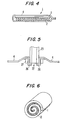
- Figure 1 is a cross-sectional view of the element containing a gas-channel-forming component enclosed by an envelope having an unreinforced edge seal;
- Figure 2 is a partial cross-sectional view of the element with an envelope having a reinforced edge seal;
- Figure 3 is a cross-sectional view of a gas-channel-forming component;
- Figure 4 is a cross-sectional view of a deaeration element containing a gas-channel-forming component;
- Figure 5 is a cross-sectional view of an example of a connection between a gas removal tube and the envelope at a port in the envelope;
- Figure 6 shows a spirally-wound element with a liquid-channel-forming component interposed between adjacent outer surfaces of the element;
- Figure 7 shows a folded element with a liquid-channel-forming component interposed between adjacent outer surface of the element;
- Figure 8 is a cross-section view of a module containing an embodiment of the assembly of the invention;
- Figure 9 is a partial cross-sectional and perspective view of a deaeration element in which both the gas-channel-forming component and liquid-channel-forming component are contained within the envelope;
- Figure 10 is a partial cross-sectional view of adjacent element layers of another deaeration element in which both the gas-channel-forming component and liquid-channel-forming component are contained within the envelope.
- With reference to the figures, the invention will be described in detail. To facilitate understanding, the same numerical identifiers for elements common to the figures will be used through the figures.
- The term "non-porous" is used herein simply to describe a material which is essentially free of pores or voids, and which is a barrier to bulk flow of liquids or gases.
- While a material may be non-porous, it may still be "permeable" to liquids or gases. The term "permeable", (and correspondingly "impermeable"), or a variation thereof, is used herein to describe the property of a material to transport (or not transport) a particular species, such as gas or water-vapor, through the material. The term describes the overall property of mass transfer by diffusion at a molecular level, and in no way implies any particular scientific mechanism by which this occurs.
- In Figure 1 is shown a cross-section of a deaeration element 1 which includes an
envelope 4 made of a single sheet of non-porous fluoropolymer film. The envelope encloses a porous gas-channel-formingmaterial 2 on each side of which is laminated a porouspolymeric membrane 3. The overlapping edges of thefluoropolymer film envelope 4 are sealed at anedge region 5 which extends along the length and across the ends of the deaeration element 1. - Non-porous fluoropolymer films are used to make the
envelope 4 of the deaeration element 1 due to their well known chemical inertness, i.e., they are highly resistant to attack by aggressive chemicals, solvents, oils, and high purity water or other aqueous liquids, and thereby minimize contamination of liquids in contact with them. Many fluoropolymers can be used so long as non-porous films made of them have sufficient chemical resistance to the liquids to which they will be exposed and are sufficiently permeable by the gases dissolved or entrained in the liquids. Preferably, the fluoropolymers are melt-processible thermoplastic fluoropolymers such as tetrafluoroethylene-hexafluoropropylene copolymer (FEP), tetrafluoroethylene-(perfluoroalkyl) vinyl ether copolymer (PFA), amorphous fluoropolymers, such as TEFLON AF® amorphous fluoropolymer, and the like. Such fluoropolymers are well know in the art and are readily available in sheet and film form from a number of suppliers. - The thickness of the non-porous fluoropolymer film influences properties such as gas permeation rate, strength, processability, durability in use, etc., and may necessitate some compromise or trade-offs between desired properties. The film used to make the
envelope 4 should be in therange 5 to 100 micrometers thick, and preferably in the range 10 to 40 micrometers thick. If the film is less than about 5 micrometers thick, it will be difficult to handle and will lack pressure resistance and durability in use. On the other hand, if the film is thicker than about 100 micrometers, gas permeation rates through the film may be too low to be useful. - There are no particular limitations on the length and width dimensions of the
envelope 4 except as dictated by deaeration performance desired and availability of materials. Typically, theenvelope 4 should be in the range 10 to 100 centimeters wide and in therange 2 to 20 meters long. As the element 1 is typically operated at a pressure differential between the outside and inside of the element, the inside being at a lower pressure, there are some practical limitations imposed due to pressure drop across the element walls or through the interior of the element. If the envelope is too long, it will be difficult to maintain the desired pressure differential across the walls of the element over its full length. On the other hand, if the envelope is too short there may not be sufficient surface area available to achieve the desired gas permeation rate. Nevertheless, even with these considerations, there is considerable flexibility in choosing suitable length and width dimensions for theenvelope 4. - The non-porous
fluoropolymer film envelope 4 can be made from a single sheet as shown in Figure 1, or can be made using two sheets of non-porous fluoropolymer film, in which case theseal region 5 extends around the entire periphery of the element. Alternatively, thin-walled tubes of a melt-processible thermoplastic fluoropolymer can be extruded or blow-molded and flattened to form theenvelope 4. In this case, only the ends will have aseal region 5. Sealing the open edges of anenvelope 4 made of a melt-processible thermoplastic fluoropolymer film can be readily accomplished by application of heat and pressure atseal regions 5 where the film overlaps the porous gas-channel-formingcomponent 2. Many heat sealing methods are known in the art and can be used. - An
alternative seal region 15 is illustrated in Figure 2. In thisconfiguration reinforcing strips 6 of porous polytetrafluoroethylene (PTFE) film are placed on the outward-facing surfaces of theenvelope 4 at theseal region 15 prior to heat sealing. When heat sealing is performed some of the melt-processible fluoropolymer film penetrates into the porous PTFE film and the strength and reliability of the seal are enhanced. The porous PTFE film also serves as an excellent release material which prevents contact between melted thermoplastic fluoropolymer and equipment surfaces applying heat and pressure to theseal region 15. Preferably, the porous PTFE film is porous expanded polytetrafluoroethylene film. - The interior of the deaeration element 1 contains a gas-channel-forming
component 2 which provides pathways through the inside of the element for gases which have permeated from the liquid through the film forming theenvelope 4, to at least one port through thefilm envelope 4 which is connected to means for transfer of gases to a location external to the apparatus. The gas-channel-forming component must be able to withstand the compressive forces exerted on it, be compatible with the gases to be removed from the liquid, and, within these limitations, have a structure as open or porous as possible so as to minimize the pressure drop through the interior of the element 1. Preferably the gas-channel-formingcomponent 2 is made of a synthetic polymer, although other materials can also be used. Suitable polymeric material and forms are known in the art and are available commercially. Suitable materials include polymers such as polyolefins, polyesters, nylons, polyurethanes, polycarbonates, polystyrenes, polyvinyl chloride, polyvinylidene chloride, and the like; or fluoropolymers such as PTFE, FEP, PFA, polyvinylfluoride, polyvinylidene fluoride, and the like. Suitable forms include nonwoven fabric, knit fabric, woven fabric or mesh, open-cell foams, porous membranes, and the like. The thickness of the gas-channel-formingcomponent 2 is preferably in the range of about 0.3 millimeters to about 2 millimeters, and should have length and width dimensions somewhat less, about 2 millimeters to about 10 millimeters less, than the length and width dimensions of theenvelope 4 in order to provide sufficient area to form theseal region 5. - It can be desirable to laminate a
porous membrane 3 to both sides of the gas-channel-formingcomponent 2, to form a subassembly as shown in Figure 3; or to one side of the gas-channel-formingcomponent 2, as shown in Figure 4, where the subassembly is shown positioned in thefluoropolymer envelope 4 of the element 1. Theporous membrane 3 provides support to the non-porous fluoropolymer film forming theenvelope 4 and helps to more uniformly distribute the compressive load on the gas-channel-formingcomponent 2 encountered during operation. By providing such support to the fluoropolymer film, a thinner film can be used to form theenvelope 4, thereby increasing the gas permeation rate from the liquid outside the element to the gas channels inside the element. Preferably theporous membrane 3 is also made of a synthetic polymer and its selection is subject to the same constraints listed above for the gas-channel-forming component. Most preferred are porous membranes of polytetrafluoroethylene. - Porous polytetrafluoroethylene sheet or film suitable for use in the invention can be made by processes known in the art, for example, by stretching or drawing processes, by papermaking processes, by processes in which filler materials are incorporated with the PTFE resin and which are subsequently removed to leave a porous structure, or by powder sintering processes. Preferably the porous polytetrafluoroethylene membrane is porous expanded polytetrafluoroethylene film having a structure of interconnected nodes and fibrils, as described in U.S. Patent Nos. 3,953,566 and 4,187,390 which describe the preferred material and processes for making them.
- The porous membrane should have a pore volume in the range of about 30 to 95 percent, a nominal pore size in the range of about 0.1 to 100 micrometers, and be about 5 to about 100 micrometers thick.
- Lamination of the
porous membrane 3 to the gas-channel-formingcomponent 2 can be done using conventional methods and equipment, for example, by adhesive bonding. The adhesive can be applied to the surface to be bonded of either layer, and should be applied in a non-continuous pattern. A non-continuous pattern of adhesive is used herein to indicate a layer of adhesive which is applied to a surface so as to not form a non-porous continuous film. For example, a layer applied to a surface as a pattern of discrete dots, a porous non-woven web or mesh, or the like. - The adhesive may be selected from many known in the art. The adhesive can be a thermoplastic, thermosetting, or reaction curing type, in liquid or solid form, selected from the classes including, but not limited to, polyamides, polyacrylamides, polyesters, polyolefins, polyurethanes, and the like. The adhesive should be applied so that it forms a porous (non-continuous) gas-permeable layer which minimizes resistance to air flow while adhering the
porous membrane 3 to the gas-channel-formingcomponent 2. Preferably, the adhesive is applied so as to cover about 30 percent or less of the surface. Suitable application means include gravure printing, spray coating, powder coating, interposing a non-woven web of adhesive, and the like. - Lamination of the
porous membrane 3 to the gas-channel-formingcomponent 2 can be also be done using conventional heat-fusing methods and equipment, for example, by application of heat and pressure in the nip between rolls, or by a heated platen press. - One or more ports, or openings, are provided in the element 1 for passage of gases out of the element. Transfer means, preferably a tube of the same melt-processible thermoplastic fluoropolymer used to form the
envelope 4, for removal of gases from inside the element to a location external to the module or apparatus in which the element 1 is positioned is connected to the port by any convenient method. The outside diameter of the tube should be about 4 millimeters to about 10 millimeters, and the wall thickness about 0.5 millimeters to about 1 millimeter. By way of example only, one such connection is illustrated in Figure 5. - In Figure 5 is shown a section of one wall of the melt-processible thermoplastic
fluoropolymer film envelope 4 in which anopening 22 leading to the inside of the element has been made. An end of atube 23, preferably of the same fluoropolymer as the envelope, is positioned around theopening 22. Afluoropolymer ring 27 andporous PTFE film 26 are pressed into place around the end of thetube 23 so that, when finally positioned, the film forming theenvelope 4 and thePTFE film 26 overlap the end of thetube 23, and the edge of thering 27 is approximately even with the end of thetube 23. The portion of theenvelope 4 overlapping the end of thetube 23 is heat sealed to the end of the tube by application of a heated plate (not shown) to the PTFE film portion overlapping the end of the tube, and a strong air-tight seal is formed. The fluoropolymer ring 25 serves as a strain relief for the connection and also prevents distortion or contraction of the envelope film during the heat sealing step. Theporous PTFE film 26 serves to reinforce the seal region and serves as a release material to prevent melted fluoropolymer from sticking to the heated plate. - To most efficiently use the element, it may be positioned in a module or apparatus in a spiral-wound configuration, as shown in Figure 6; or in a folded configuration, as shown in Figure 7. In such configurations a space between adjacent element layers must be provided to permit the liquid to be deaerated to contact the outer surface of the element and to permit the liquid to flow through the module. This space can be provided by interposing a liquid-channel-forming
component 12 between adjacent layers of the element 1, as shown in Figures 6 and 7. The void size and distance between element layers provided by the liquid-channel-formingcomponent 12 should be in the range 50 to 1000 micrometers, preferably in the range 100 to 400 micrometers. If the spacing is larger than 1000 micrometers, deaeration performance will suffer as the diffusion distance for the gas through the liquid will become too great. If the spacing is less than 50 micrometers, the pressure drop of the liquid through the liquid-channel-forming component may become too high. The length of the liquid-channel-forming compnonent should be roughly the same as the length of the deaeration element. The width of the liquid-channel-forming component should be at least as wide as the deaeration element, and may be somewhat wider (about 1-2 centimeters) so as to extend beyond and protect the longitudinal edges of the fluoropolymer film envelope. - As with the gas-channel-forming component described earlier, suitable materials include polymers such as polyolefins, polyesters, nylons, polyurethanes, polycarbonates, polystyrenes, polyvinyl chloride, polyvinylidene chloride, and the like, or fluoropolymers such as PTFE, FEP, PFA, polyvinylfluoride, polyvinylidene fluoride, and the like, in forms such as nonwoven fabric, knit fabric, woven fabric or mesh, and the like. In systems in which chemically aggressive and high purity liquids, or special liquids in which contamination must be minimized, it is preferred that the liquid-channel-forming component be made of a fluoropolymer such as PTFE, PFA, FEP.
- A cross-sectional view of a deaeration apparatus or module containing a spiral-wound assembly of the invention is shown in Figure 8. The
module 41 has a cylindrical casing body 41a, and end caps 41b at each end. A spirally-wound element 1, with a liquid-channel-formingcomponent 12 interposed between adjacent layers of the element, is disposed in the casing body. Agas removal tube 23 is connected to the element 1 and exits the module through a fitting in an end cap 41b. An inlet opening 46 for a liquid to be deaerated, and avent opening 48 for removal of air during initial filling of the module with the liquid, are provided in one end cap. In the opposing end cap is anoutlet opening 47 for liquid which has been deaerated. At each end of the spiral-wound assembly is aporous spacer element 49 which serves both to space the assembly within the module and provides passages for liquid. The module shown is a conventional type, well known in the art, as are the materials and constructions methods to make it, which are selected according to the fluids and operating conditions which will be encountered in the projected end-use. Again, in systems in which chemically aggressive and high purity liquids, or special liquids in which contamination must be minimized, it is preferred that the module be made of a fluoropolymer such as PTFE, PFA or FEP, or the liquid-wetted surfaces be lined with a fluoropolymer. - After the module is initially filled with a liquid to be deaerated, and trapped air exhausted through the
vent opening 48, liquid flow through the liquid-channel-forming component is begun and the interior of the element 1 is operated at a pressure lower than the pressure of the liquid flowing over the outer surface of the element, for example, by drawing a vacuum through thegas removal tube 23. Gas dissolved in the liquid, driven by the pressure differential between the liquid and the interior of the element, diffuses out of the liquid and permeates through the fluoropolymer film forming the envelope of the element, passes through the gas channels formed inside the element to the gas removal tube, and thence out of the module. At the same time, the dissolved gas concentration in the liquid becomes progressively lower as the liquid flows over and past the surface of the deaeration element. - The deaeration assembly of the invention accomplishes the efficient removal of gases dissolved not only in ordinary liquids such as water or aqueous solutions, but also in chemically aggressive, high purity, and other special liquids, while contributing virtually no contaminants to the liquids.
- Referring to Figures 9 and 10, another embodiment of the deaeration assembly of the invention is shown. The second embodiment differs from the embodiment described hereinabove in that [i] both the liquid-channel-forming component and gas-channel-forming component are enclosed within the fluoropolymer film forming the envelope of the element, [ii] the liquid-channel-forming component is contiguous with at least one inward-facing surface of the fluoropolymer film, [iii] the fluoropolymer film conforms to the contours of the liquid-channel-forming component thereby creating channels along the outward-facing surface of the fluoropolymer film, and [iv] the liquid-channel-forming component does not come in contact with the liquid to be deaerated. In other respects, the second embodiment is the same as the embodiment described earlier.
- Figure 9 shows an
element 51 consisting of a gas-channel-formingsubassembly 52 of a porous membrane laminated to each side of a gas-channel-forming component (as depicted in Figure 3), and a liquid-channel-formingcomponent 53 of a porous ribbed material, each component contiguous with an inward-facing surface of anenvelope 54 of a non-porous fluoropolymer film. The ribbed material of the liquid-channel-forming component can be, for example, a knitted ribbed fabric of synthetic polymer fibers. In operation, the pressure differential between the outside and the inside of the element causes the inward-facing surface of the fluoropolymer film contiguous with the liquid-channel-forming component to contact and generally conform to the contours of the liquid-channel-formingcomponent 53 to formchannels 55, defined by the ribs of the material, for passage of liquids over the outward-facing surface of theelement 51. - Figure 10 shows sections of adjacent element layers 61 of another deaeration element in which both the gas-channel-forming
subassembly 62 and liquid-channel-formingcomponent 63 of a woven material are contained within thefluoropolymer film envelope 64. The woven material of the liquid-channel-forming component can be, for example, a woven fabric or mesh of synthetic polymer fibers. As noted above, in operation, the pressure differential between the outside and the inside of the element causes the inward-facing surface of the fluoropolymer film contiguous with the liquid-channel-forming component to generally conform to the high spots and depressions of the woven material to form corresponding high spots and depressions in the outward-facing surface to formchannels 65 for passage of liquids over the outward-facing surface of theelement 61. - In this embodiment of the assembly of the invention a liquid-channel-forming component external to the element is not needed which significantly reduces the risk of contamination of the liquids, reduces material costs, and simplifies manufacture of the assembly.
- On each side of a 250 micrometers thick polyester knitted fabric (Stock No. 2020, 20-denier staple fiber, made by Toray Co) was laminated a 30 micrometers thick porous expanded PTFE membrane (made by Japan Gore-Tex, Inc.) having a pore volume of 82%. The laminate thus produced was cut to make a gas removal subassembly 20 centimeters wide and 9 meters long of the type shown in Figure 3.
- The subassembly was placed on a 12.5 mm thick FEP film (made by Daikin Industries) which was then folded over the subassembly, and the open ends and longitudinal edge heat-sealed to form an element about 20 cm wide and 9.3 m long of the type shown in Figure 1. An FEP tube, 6 mm outside diameter and 4 mm inside diameter, was connected to one end of the element to serve as a gas removal tube. The tube was connected and heat-sealed to the element by the method shown in Figure 5.
- A woven mesh of PFA (made by Gunze Co.), about 8 mesh/cm (20 mesh/inch) and 0.51 mm thick, was cut to a width of 24 cm and a lenth of 9.3 m to serve as a liquid-channel-forming component. The liquid-channel-forming component was placed on and aligned over the element, and the element, with the liquid-channel-forming component interposed between layers, was rolled up (as shown in Figure 6) to form a spiral-wound deaeration assembly of 101.6 mm diameter and 24 cm length which provided 3.72 m2 of surface area for liquid contact. The deaeration assembly thus made was installed in a module of the type shown in Figure 8 which had a casing body and end caps made of PTFE.
- The deaeration assembly was tested by flowing tap-water having an initial dissolved oxygen concentration of 8.2 ppm through the module at a rate of 300 cc/minute at 25°C. The pressure inside the element was reduced and kept at about 100 Torr by a vacuum pump.
- The dissolved oxygen concentration of the deaerated liquid at the outlet of the module was measured and found to be 2.9 ppm, which is a good value.
- A second test under the same conditions except that tap-water containing 9% neutral detergent (with surfactant) was used. The dissolved oxygen content of the deaerated liquid at the outlet was found to be 2.95 ppm, which is also a good value.
- After the second test, the module was emptied of water and filled with 98% ethyl alcohol. The pressure inside the element was reduced to 100 Torr. No alcohol was detected in the gas sampled from the gas removal tube, confirming that the alcohol liquid did not permeate through the FEP deaeration film.
- Hot water (90°C) was also passed through the module, after which the apparatus was disassembled and the various components inspected. No change whatsoever was seen in any of the materials.
- It is apparent from the above that the deaeration assembly of the invention permits deaeration of a liquid containing a surfactant, and that there is no problem with washing the assembly with 90°C hot water. Furthermore since the deaeration apparatus used in this example makes use of FEP, PFA, or PTFE for all its liquid-wetted parts, it can also be used with chemically aggressive liquids which are strongly acidic or alkaline.
- A deaeration assembly was made as described in Example 1, except that the FEP film was 25 micrometers thick.
- The deaeration assembly was installed in the module and the same tests performed as described in Example 1, except that the liquid flow rate was 200 cc/minute.
- The dissolved oxygen content of the deaerated liquid at the module outlet was found to be 2.95 ppm, which is a good value. The results of the other tests were the same as described in Example 1.
- A gas removal subassembly was made as described in Example 1.
- The subassembly was placed on a 25 mm thick FEP film (made by Daikin Industries). A woven mesh of PFA (made by Gunze Co.), about 8 mesh/cm (20 mesh/inch) and 0.51 mm thick to serve as the liquid-channel-forming component, was cut to the same width and lenth as the subassembly. The liquid-channel-forming component was placed on and aligned over the gas removal subassembly. The FEP film was then folded over the subassembly and liquid-channel-forming component, and the open ends and longitudinal edge heat-sealed to form an element about 20 cm wide and 9.3 m long of the type shown in Figure 9. An FEP tube, 6 mm outside diameter and 4 mm inside diameter, was connected to one end of the element to serve as a gas removal tube. The tube was connected and heat-sealed to the element by the method shown in Figure 5.
- The element, with the liquid-channel-forming component and gas removal subassembly enclosed within the FEP film envelope, was rolled up to form a spiral-wound deaeration assembly which provided about 3.72 m2 of surface area for liquid contact. The deaeration assembly thus made was installed in a module and tested as described in Example 1.
- The dissolved oxygen content of the deaerated liquid at the module outlet was found to be 2.7 ppm, which is a good value. The results of the other tests were the same as described in Example 1.
- A deaeration assembly having the same structure and dimensions as described in Example 1 was made, the only difference being that the FEP film was 25 micrometers thick and was extruded in tubular form. A jig was prepared and the gas removal subassembly was drawn into the tube, thus only the ends of the tube required sealing. This procedure greatly simplified and shortened the production process to form the deaeration assembly. The deaeration assembly thus made was installed in a module and tested as described in Example 1.
- The dissolved oxygen content of the deaerated liquid at the module outlet was found to be 2.95 ppm, which is a good value. The results of the other tests were the same as described in Example 1.
- A deaeration assembly having the same structure and dimensions as described in Example 3 was made, the only difference being that the FEP film was extruded in tubular form. A jig was used to simultaneously draw the gas removal subassembly and liquid-channel-forming component into the tube, thus only the ends of the tube required sealing. This procedure greatly simplified and shortened the production process to form the deaeration assembly. The deaeration assembly thus made was Installed in a module and tested as described in Example 1.
- The dissolved oxygen content of the deaerated liquid at the module outlet was found to be 3.02, which is a good value. The results of the other tests were the same as described in Example 1.
Claims (8)
- A deaeration assembly for removal of a gas from a liquid comprising:(a) a deaeration element having a gas-channel-forming component enclosed and sealed within an envelope formed of a non-porous fluoropolymer film, said envelope having inward-facing and outward-facing surfaces and at least one port leading from the inside to the outside of said envelope for passage of gases permeating into the element to a location external to the assembly; and(b) a liquid-channel-forming component contiguous with at least one outward-facing surface of said fluoropolymer film envelope.
- A deaeration assembly for removal of a gas from a liquid comprising a deaeration element having a gas-channel-forming component and a liquid-channel-forming component enclosed and sealed within an envelope formed of a non-porous fluoropolymer film, said envelope having inward-facing and outward-facing surfaces and at least one port leading from the inside to the outside of said envelope for passage of gases permeating into the element to a location external to the assembly;wherein said liquid-channel-forming component is contiguous with at least one inward-facing surface of said fluoropolymer film envelope, andwherein the region of said fluoropolymer film envelope in contact with said liquid-channel-forming component conforms to the channel-forming contours of the liquid-channel-forming component to form liquid channels in said outward-facing surface.
- A deaeration assembly as claimed in claim 1 or 2, wherein said envelope is formed of a non-porous film of tetrafluoroethylene-hexafluoropropylene copolymer.
- A deaeration assembly as claimed in any of claims 1 to 3, wherein said liquid-channel-forming component is formed of a fluoropolymer material.
- A deaeration assembly as claimed in any preceding claim, in which said gas-channel-forming component has continuous interconnected pores and passageways throughout its structure to facilitate the passage of gases therethrough.
- A deaeration assembly as claimed in any preceding claim, wherein each channel-forming component comprises at least one synthetic polymeric porous material in the form of a nonwoven fabric, knit fabric, woven fabric, woven mesh, or a porous membrane.
- A deaeration element for a deaeration assembly as claimed in claim 1, said element having a gas-channel-forming component enclosed and sealed within an envelope formed of a non-porous fluoropolymer film, said envelope having inward-facing and outward-facing surfaces and at least one port leading from the inside to the outside of said envelope for passage of gases permeating into the element to a location external to the element; and
at least one outward-facing surface of said fluoropolymer film envelope being adapted to be contiguous with a liquid-channel-forming component. - A deaeration element for a deaeration assembly as claimed in claim 7, said element having a gas-channel-forming component and a liquid-channel-forming component enclosed and sealed within said envelope;wherein at least one inward-facing surface of said fluoropolymer film envelope is adapted to be contiguous with said liquid-channel-forming component; andwherein the region of said envelope in contact with said liquid-channel-forming component conforms to channel-forming contours of the liquid-channel-forming component to form liquid channels in said outward-facing surface.
Applications Claiming Priority (3)
| Application Number | Priority Date | Filing Date | Title |
|---|---|---|---|
| JP8065389A JP2969075B2 (en) | 1996-02-26 | 1996-02-26 | Degassing device |
| JP6538996 | 1996-02-26 | ||
| JP65389/96 | 1996-02-26 |
Publications (2)
| Publication Number | Publication Date |
|---|---|
| EP0791383A1 true EP0791383A1 (en) | 1997-08-27 |
| EP0791383B1 EP0791383B1 (en) | 2003-06-04 |
Family
ID=13285595
Family Applications (1)
| Application Number | Title | Priority Date | Filing Date |
|---|---|---|---|
| EP97301285A Expired - Lifetime EP0791383B1 (en) | 1996-02-26 | 1997-02-26 | An assembly for deaeration of liquids |
Country Status (4)
| Country | Link |
|---|---|
| US (1) | US5830261A (en) |
| EP (1) | EP0791383B1 (en) |
| JP (1) | JP2969075B2 (en) |
| DE (1) | DE69722481T2 (en) |
Cited By (102)
| Publication number | Priority date | Publication date | Assignee | Title |
|---|---|---|---|---|
| EP1464376A1 (en) * | 2003-04-04 | 2004-10-06 | United Technologies Corporation | Planar membrane deoxygenator |
| EP1810741A2 (en) | 2006-01-18 | 2007-07-25 | United Technologies Corporation | Fuel deoxygenator with non-planar fuel channel and oxygen permeable membrane |
| EP1541227A3 (en) * | 2003-12-12 | 2008-12-03 | United Technologies Corporation | Acoustic fuel deoxygenation system |
| US8540807B2 (en) | 2008-10-30 | 2013-09-24 | Porous Media Corporation | Venting and filtration systems with gas permeable membrane |
| US9695751B2 (en) | 2012-01-31 | 2017-07-04 | United Technologies Corporation | Geared turbofan gas turbine engine architecture |
| US9739206B2 (en) | 2012-01-31 | 2017-08-22 | United Technologies Corporation | Geared turbofan gas turbine engine architecture |
| US9835052B2 (en) | 2012-01-31 | 2017-12-05 | United Technologies Corporation | Gas turbine engine with high speed low pressure turbine section and bearing support features |
| US9840969B2 (en) | 2012-05-31 | 2017-12-12 | United Technologies Corporation | Gear system architecture for gas turbine engine |
| US9879608B2 (en) | 2014-03-17 | 2018-01-30 | United Technologies Corporation | Oil loss protection for a fan drive gear system |
| US9926885B2 (en) | 2011-07-05 | 2018-03-27 | United Technologies Corporation | Efficient, low pressure ratio propulsor for gas turbine engines |
| US9951860B2 (en) | 2006-08-15 | 2018-04-24 | United Technologies Corporation | Ring gear mounting arrangement with oil scavenge scheme |
| US9988908B2 (en) | 2014-02-19 | 2018-06-05 | United Technologies Corporation | Gas turbine engine airfoil |
| US10047699B2 (en) | 2013-03-15 | 2018-08-14 | United Technologies Corporation | Thrust efficient turbofan engine |
| US10060357B2 (en) | 2007-08-01 | 2018-08-28 | United Technologies Corporation | Turbine section of high bypass turbofan |
| US10082105B2 (en) | 2006-08-15 | 2018-09-25 | United Technologies Corporation | Gas turbine engine with geared architecture |
| US10087885B2 (en) | 2007-08-23 | 2018-10-02 | United Technologies Corporation | Gas turbine engine with axial movable fan variable area nozzle |
| US10196989B2 (en) | 2006-08-15 | 2019-02-05 | United Technologies Corporation | Gas turbine engine gear train |
| US10227893B2 (en) | 2011-06-08 | 2019-03-12 | United Technologies Corporation | Flexible support structure for a geared architecture gas turbine engine |
| US10233773B2 (en) | 2015-11-17 | 2019-03-19 | United Technologies Corporation | Monitoring system for non-ferrous metal particles |
| US10287914B2 (en) | 2012-01-31 | 2019-05-14 | United Technologies Corporation | Gas turbine engine with high speed low pressure turbine section and bearing support features |
| US10301971B2 (en) | 2012-12-20 | 2019-05-28 | United Technologies Corporation | Low pressure ratio fan engine having a dimensional relationship between inlet and fan size |
| US10309414B2 (en) | 2014-02-19 | 2019-06-04 | United Technologies Corporation | Gas turbine engine airfoil |
| US10358924B2 (en) | 2015-03-18 | 2019-07-23 | United Technologies Corporation | Turbofan arrangement with blade channel variations |
| US10436116B2 (en) | 2012-03-30 | 2019-10-08 | United Technologies Corporation | Gas turbine engine geared architecture axial retention arrangement |
| US10451004B2 (en) | 2008-06-02 | 2019-10-22 | United Technologies Corporation | Gas turbine engine with low stage count low pressure turbine |
| US10465549B2 (en) | 2012-01-10 | 2019-11-05 | United Technologies Corporation | Gas turbine engine forward bearing compartment architecture |
| US10544741B2 (en) | 2007-03-05 | 2020-01-28 | United Technologies Corporation | Flutter sensing and control system for a gas turbine engine |
| US10550852B2 (en) | 2014-02-19 | 2020-02-04 | United Technologies Corporation | Gas turbine engine airfoil |
| US10563576B2 (en) | 2013-03-15 | 2020-02-18 | United Technologies Corporation | Turbofan engine bearing and gearbox arrangement |
| US10577965B2 (en) | 2006-08-15 | 2020-03-03 | United Technologies Corporation | Epicyclic gear train |
| US10605351B2 (en) | 2006-07-05 | 2020-03-31 | United Technologies Corporation | Oil baffle for gas turbine fan drive gear system |
| US10605167B2 (en) | 2011-04-15 | 2020-03-31 | United Technologies Corporation | Gas turbine engine front center body architecture |
| US10655538B2 (en) | 2012-02-29 | 2020-05-19 | United Technologies Corporation | Geared gas turbine engine with reduced fan noise |
| US10677192B2 (en) | 2006-10-12 | 2020-06-09 | Raytheon Technologies Corporation | Dual function cascade integrated variable area fan nozzle and thrust reverser |
| US10731563B2 (en) | 2012-01-31 | 2020-08-04 | Raytheon Technologies Corporation | Compressed air bleed supply for buffer system |
| US10731559B2 (en) | 2015-04-27 | 2020-08-04 | Raytheon Technologies Corporation | Lubrication system for gas turbine engines |
| US10753285B2 (en) | 2006-07-05 | 2020-08-25 | Raytheon Technologies Corporation | Method of assembly for gas turbine fan drive gear system |
| US10760488B2 (en) | 2013-11-22 | 2020-09-01 | Raytheon Technologies Corporation | Geared turbofan engine gearbox arrangement |
| US10781755B2 (en) | 2012-01-31 | 2020-09-22 | Raytheon Technologies Corporation | Turbine engine gearbox |
| US10794292B2 (en) | 2012-01-31 | 2020-10-06 | United Technologies Corporation | Geared turbofan gas turbine engine architecture |
| US10801355B2 (en) | 2015-12-01 | 2020-10-13 | Raytheon Technologies Corporation | Geared turbofan with four star/planetary gear reduction |
| US10808617B2 (en) | 2012-09-28 | 2020-10-20 | Raytheon Technologies Corporation | Split-zone flow metering T-tube |
| US10815888B2 (en) | 2011-07-29 | 2020-10-27 | Raytheon Technologies Corporation | Geared turbofan bearing arrangement |
| US10823052B2 (en) | 2013-10-16 | 2020-11-03 | Raytheon Technologies Corporation | Geared turbofan engine with targeted modular efficiency |
| US10830178B2 (en) | 2012-01-31 | 2020-11-10 | Raytheon Technologies Corporation | Gas turbine engine variable area fan nozzle control |
| US10830153B2 (en) | 2012-04-02 | 2020-11-10 | Raytheon Technologies Corporation | Geared turbofan engine with power density range |
| US10830152B2 (en) | 2007-09-21 | 2020-11-10 | Raytheon Technologies Corporation | Gas turbine engine compressor arrangement |
| US10890195B2 (en) | 2014-02-19 | 2021-01-12 | Raytheon Technologies Corporation | Gas turbine engine airfoil |
| US10907482B2 (en) | 2012-01-31 | 2021-02-02 | Raytheon Technologies Corporation | Turbine blade damper seal |
| US10914315B2 (en) | 2014-02-19 | 2021-02-09 | Raytheon Technologies Corporation | Gas turbine engine airfoil |
| US10989143B2 (en) | 2009-03-17 | 2021-04-27 | Raytheon Technologies Corporation | Gas turbine engine bifurcation located fan variable area nozzle |
| US11008947B2 (en) | 2014-03-07 | 2021-05-18 | Raytheon Technologies Corporation | Geared turbofan with integral front support and carrier |
| US11015550B2 (en) | 2012-12-20 | 2021-05-25 | Raytheon Technologies Corporation | Low pressure ratio fan engine having a dimensional relationship between inlet and fan size |
| US11041507B2 (en) | 2014-02-19 | 2021-06-22 | Raytheon Technologies Corporation | Gas turbine engine airfoil |
| US11047337B2 (en) | 2011-06-08 | 2021-06-29 | Raytheon Technologies Corporation | Geared architecture for high speed and small volume fan drive turbine |
| US11053816B2 (en) | 2013-05-09 | 2021-07-06 | Raytheon Technologies Corporation | Turbofan engine front section |
| US11053843B2 (en) | 2012-04-02 | 2021-07-06 | Raytheon Technologies Corporation | Geared turbofan engine with a high ratio of thrust to turbine volume |
| US11053811B2 (en) | 2015-06-23 | 2021-07-06 | Raytheon Technologies Corporation | Roller bearings for high ratio geared turbofan engine |
| US11066954B2 (en) | 2014-07-29 | 2021-07-20 | Raytheon Technologies Corporation | Geared gas turbine engine with oil deaerator and air removal |
| US11073157B2 (en) | 2011-07-05 | 2021-07-27 | Raytheon Technologies Corporation | Efficient, low pressure ratio propulsor for gas turbine engines |
| US11085400B2 (en) | 2015-02-06 | 2021-08-10 | Raytheon Technologies Corporation | Propulsion system arrangement for turbofan gas turbine engine |
| US11098644B2 (en) | 2012-01-31 | 2021-08-24 | Raytheon Technologies Corporation | Gas turbine engine buffer system |
| US11125155B2 (en) | 2013-11-01 | 2021-09-21 | Raytheon Technologies Corporation | Geared turbofan arrangement with core split power ratio |
| US11125167B2 (en) | 2012-05-31 | 2021-09-21 | Raytheon Technologies Corporation | Fundamental gear system architecture |
| US11136920B2 (en) | 2013-03-12 | 2021-10-05 | Raytheon Technologies Corporation | Flexible coupling for geared turbine engine |
| US11143109B2 (en) | 2013-03-14 | 2021-10-12 | Raytheon Technologies Corporation | Low noise turbine for geared gas turbine engine |
| US11149689B2 (en) | 2012-01-31 | 2021-10-19 | Raytheon Technologies Corporation | Gas turbine engine shaft bearing configuration |
| US11149650B2 (en) | 2007-08-01 | 2021-10-19 | Raytheon Technologies Corporation | Turbine section of high bypass turbofan |
| US11174936B2 (en) | 2011-06-08 | 2021-11-16 | Raytheon Technologies Corporation | Flexible support structure for a geared architecture gas turbine engine |
| US11181074B2 (en) | 2012-01-31 | 2021-11-23 | Raytheon Technologies Corporation | Variable area fan nozzle with wall thickness distribution |
| US11187160B2 (en) | 2017-01-03 | 2021-11-30 | Raytheon Technologies Corporation | Geared turbofan with non-epicyclic gear reduction system |
| US11193497B2 (en) | 2014-02-19 | 2021-12-07 | Raytheon Technologies Corporation | Gas turbine engine airfoil |
| US11193496B2 (en) | 2014-02-19 | 2021-12-07 | Raytheon Technologies Corporation | Gas turbine engine airfoil |
| US11209013B2 (en) | 2014-02-19 | 2021-12-28 | Raytheon Technologies Corporation | Gas turbine engine airfoil |
| US11215143B2 (en) | 2013-11-01 | 2022-01-04 | Raytheon Technologies Corporation | Geared turbofan arrangement with core split power ratio |
| US11236679B2 (en) | 2012-10-08 | 2022-02-01 | Raytheon Technologies Corporation | Geared turbine engine with relatively lightweight propulsor module |
| US11242805B2 (en) | 2007-08-01 | 2022-02-08 | Raytheon Technologies Corporation | Turbine section of high bypass turbofan |
| US11286852B2 (en) | 2012-01-31 | 2022-03-29 | Raytheon Technologies Corporation | Gas turbine engine buffer system |
| US11300141B2 (en) | 2015-04-07 | 2022-04-12 | Raytheon Technologies Corporation | Modal noise reduction for gas turbine engine |
| US11346289B2 (en) | 2007-08-01 | 2022-05-31 | Raytheon Technologies Corporation | Turbine section of high bypass turbofan |
| US11384657B2 (en) | 2017-06-12 | 2022-07-12 | Raytheon Technologies Corporation | Geared gas turbine engine with gear driving low pressure compressor and fan at a common speed and a shear section to provide overspeed protection |
| US11391216B2 (en) | 2013-02-06 | 2022-07-19 | Raytheon Technologies Corporation | Elongated geared turbofan with high bypass ratio |
| US11391294B2 (en) | 2014-02-19 | 2022-07-19 | Raytheon Technologies Corporation | Gas turbine engine airfoil |
| US11408372B2 (en) | 2007-08-28 | 2022-08-09 | Raytheon Technologies Corporation | Gas turbine engine front architecture |
| US11408436B2 (en) | 2014-02-19 | 2022-08-09 | Raytheon Technologies Corporation | Gas turbine engine airfoil |
| US11486311B2 (en) | 2007-08-01 | 2022-11-01 | Raytheon Technologies Corporation | Turbine section of high bypass turbofan |
| US11486269B2 (en) | 2012-01-31 | 2022-11-01 | Raytheon Technologies Corporation | Gas turbine engine shaft bearing configuration |
| US11499476B2 (en) | 2012-01-31 | 2022-11-15 | Raytheon Technologies Corporation | Gas turbine engine buffer system |
| US11536204B2 (en) | 2018-01-03 | 2022-12-27 | Raytheon Technologies Corporation | Method of assembly for gear system with rotating carrier |
| US11566587B2 (en) | 2012-01-24 | 2023-01-31 | Raytheon Technologies Corporation | Geared turbomachine fan and compressor rotation |
| US11585276B2 (en) | 2012-01-31 | 2023-02-21 | Raytheon Technologies Corporation | Gas turbine engine with high speed low pressure turbine section and bearing support features |
| US11719245B2 (en) | 2021-07-19 | 2023-08-08 | Raytheon Technologies Corporation | Compressor arrangement for a gas turbine engine |
| US11719161B2 (en) | 2013-03-14 | 2023-08-08 | Raytheon Technologies Corporation | Low noise turbine for geared gas turbine engine |
| US11725670B2 (en) | 2012-01-31 | 2023-08-15 | Raytheon Technologies Corporation | Compressor flowpath |
| US11725589B2 (en) | 2014-07-01 | 2023-08-15 | Raytheon Technologies Corporation | Geared gas turbine engine with oil deaerator |
| US11754000B2 (en) | 2021-07-19 | 2023-09-12 | Rtx Corporation | High and low spool configuration for a gas turbine engine |
| US11753951B2 (en) | 2018-10-18 | 2023-09-12 | Rtx Corporation | Rotor assembly for gas turbine engines |
| US11781490B2 (en) | 2012-10-09 | 2023-10-10 | Rtx Corporation | Operability geared turbofan engine including compressor section variable guide vanes |
| US11781506B2 (en) | 2020-06-03 | 2023-10-10 | Rtx Corporation | Splitter and guide vane arrangement for gas turbine engines |
| US11815001B2 (en) | 2010-10-12 | 2023-11-14 | Rtx Corporation | Planetary gear system arrangement with auxiliary oil system |
| US11814968B2 (en) | 2021-07-19 | 2023-11-14 | Rtx Corporation | Gas turbine engine with idle thrust ratio |
| US11971051B2 (en) | 2023-06-09 | 2024-04-30 | Rtx Corporation | Compressor flowpath |
Families Citing this family (32)
| Publication number | Priority date | Publication date | Assignee | Title |
|---|---|---|---|---|
| JP3273735B2 (en) * | 1996-05-17 | 2002-04-15 | 日東電工株式会社 | Polytetrafluoroethylene porous membrane and method for producing the same, sheet-like polytetrafluoroethylene molded article, and filter medium for air filter |
| JP3280880B2 (en) * | 1997-02-07 | 2002-05-13 | 東京エレクトロン株式会社 | Degassing mechanism and processing apparatus using the same |
| DE69828594T2 (en) * | 1998-07-17 | 2005-06-16 | Agilent Technologies Inc., A Delaware Corp., Palo Alto | Device for degassing liquids |
| US6048383A (en) * | 1998-10-08 | 2000-04-11 | International Fuel Cells, L.L.C. | Mass transfer composite membrane for a fuel cell power plant |
| JP2000225328A (en) * | 1998-11-30 | 2000-08-15 | Nitto Denko Corp | Filter medium for filter |
| JP2000176261A (en) * | 1998-12-11 | 2000-06-27 | Fuji Photo Film Co Ltd | Method for deaerating water-based coating liquid |
| WO2000058603A1 (en) * | 1999-03-27 | 2000-10-05 | Chevron U.S.A. Inc. | Method and apparatus for wellbore gas separation |
| WO2001027552A1 (en) * | 1999-10-08 | 2001-04-19 | Carrier Corporation | A plate-type heat exchanger |
| US6613241B1 (en) * | 1999-10-29 | 2003-09-02 | California Insitute Of Technology | MEMS elements with integrated porous membranes and method of making the same |
| US6315815B1 (en) * | 1999-12-16 | 2001-11-13 | United Technologies Corporation | Membrane based fuel deoxygenator |
| US6402818B1 (en) * | 2000-06-02 | 2002-06-11 | Celgard Inc. | Degassing a liquid with a membrane contactor |
| US6391096B1 (en) | 2000-06-09 | 2002-05-21 | Serveron Corporation | Apparatus and method for extracting and analyzing gas |
| WO2002062446A1 (en) * | 2001-02-07 | 2002-08-15 | Mykrolis Corporation | Process for degassing an aqueous plating solution |
| US6596058B2 (en) | 2001-07-16 | 2003-07-22 | Systec, Inc. | Film degassing system |
| US6942718B1 (en) * | 2002-01-31 | 2005-09-13 | Ball Aerospace & Technologies Corp. | Orientation insensitive combined liquid reservoir and gas/liquid separator |
| US6726743B2 (en) | 2002-06-18 | 2004-04-27 | 3M Innovative Properties Company | Electrostatic deaeration method and apparatus |
| US6977009B2 (en) * | 2002-08-07 | 2005-12-20 | Hewlett-Packard Development Company, L.P. | Metal coated polymer electrolyte membrane having a reinforcement structure |
| US6968728B2 (en) * | 2003-07-10 | 2005-11-29 | Hydro Quebec | Test tap adapter for extracting dissolved gases from insulating oil and measuring electrical parameters of a transformer bushing |
| US7097690B2 (en) * | 2003-10-10 | 2006-08-29 | Scimed Life Systems, Inc. | Apparatus and method for removing gasses from a liquid |
| US20050092175A1 (en) * | 2003-10-29 | 2005-05-05 | Meacham G.B. K. | Noble metal gas barriers |
| US7074255B2 (en) * | 2003-10-29 | 2006-07-11 | Meacham G B Kirby | Noble metal gas barriers |
| US7022157B2 (en) * | 2003-11-12 | 2006-04-04 | Agilent Technologies, Inc. | Devices and methods for performing array based assays |
| US7459081B2 (en) * | 2004-11-30 | 2008-12-02 | Phyre Technologies, Inc. | Contacting systems and methods and uses thereof |
| JP2008521596A (en) * | 2004-11-30 | 2008-06-26 | ファイア テクノロジーズ、インコーポレイテッド | Contacting device and method and use thereof |
| US7465335B2 (en) * | 2005-02-02 | 2008-12-16 | United Technologies Corporation | Fuel deoxygenation system with textured oxygen permeable membrane |
| US7393388B2 (en) * | 2005-05-13 | 2008-07-01 | United Technologies Corporation | Spiral wound fuel stabilization unit for fuel de-oxygenation |
| US7465336B2 (en) * | 2005-06-09 | 2008-12-16 | United Technologies Corporation | Fuel deoxygenation system with non-planar plate members |
| TWI388368B (en) * | 2006-05-01 | 2013-03-11 | Nitto Denko Corp | Degassing apparatus |
| EP1992400A1 (en) * | 2007-05-18 | 2008-11-19 | Vlaamse Instelling Voor Technologisch Onderzoek (Vito) | Membrane bag and method of producing same |
| US8075675B2 (en) * | 2008-06-12 | 2011-12-13 | Serveron Corporation | Apparatus and method for extracting gas from liquid |
| US8038770B2 (en) * | 2008-12-01 | 2011-10-18 | Eaton Corporation | Separator for degassing fluid |
| US8177884B2 (en) | 2009-05-20 | 2012-05-15 | United Technologies Corporation | Fuel deoxygenator with porous support plate |
Citations (7)
| Publication number | Priority date | Publication date | Assignee | Title |
|---|---|---|---|---|
| US4187390A (en) * | 1970-05-21 | 1980-02-05 | W. L. Gore & Associates, Inc. | Porous products and process therefor |
| JPS6463007A (en) * | 1987-09-03 | 1989-03-09 | Japan Gore Tex Inc | Degasifying mechanism |
| EP0354797A2 (en) * | 1988-08-12 | 1990-02-14 | Japan Gore-Tex, Inc. | Degassing device |
| EP0360009A2 (en) * | 1988-08-20 | 1990-03-28 | Nitto Denko Corporation | Method of removing dissolved gas from liquid |
| EP0376638A2 (en) * | 1988-12-29 | 1990-07-04 | Japan Gore-Tex, Inc. | A degassing tube for solvents |
| EP0408769A1 (en) * | 1989-02-03 | 1991-01-23 | Japan Gore-Tex, Inc. | Deaerating film and deaerating method |
| EP0448973A1 (en) * | 1990-02-27 | 1991-10-02 | Toray Industries, Inc. | Spiral wound gas permeable membrane module and apparatus and method for using the same |
Family Cites Families (21)
| Publication number | Priority date | Publication date | Assignee | Title |
|---|---|---|---|---|
| US2597907A (en) * | 1950-03-31 | 1952-05-27 | Waldo A Steiner | Apparatus for the separation of gases by fractional permeation through membranes |
| BE711789A (en) * | 1968-03-07 | 1968-09-09 | ||
| US3668837A (en) * | 1970-02-13 | 1972-06-13 | Pall Corp | Separator of the semipermeable membrane type |
| US3735562A (en) * | 1971-06-09 | 1973-05-29 | Gulf Research Development Co | Membrane gas extractor |
| US3911080A (en) * | 1971-09-10 | 1975-10-07 | Wright H Dudley | Air pollution control |
| US4004587A (en) * | 1975-06-13 | 1977-01-25 | Baxter Travenol Laboratories, Inc. | Parenteral liquid administration set with non-air blocking filter |
| US4190426A (en) * | 1977-11-30 | 1980-02-26 | Baxter Travenol Laboratories, Inc. | Gas separating and venting filter |
| JPS55119418A (en) * | 1979-03-06 | 1980-09-13 | Daishiro Fujishima | Gas adsorption sheet |
| US4274848A (en) * | 1979-09-24 | 1981-06-23 | Hollister Incorporated | Gas-venting filter for collection appliance |
| JPS61216713A (en) * | 1985-03-20 | 1986-09-26 | Matsushita Electric Ind Co Ltd | Gas permeable membrane module |
| JPS61278328A (en) * | 1985-06-04 | 1986-12-09 | Matsushita Electric Ind Co Ltd | Gas permeable membrane module |
| JPS621405A (en) * | 1985-06-28 | 1987-01-07 | Toray Ind Inc | Fluid separator |
| JPH0232929U (en) * | 1988-08-19 | 1990-03-01 | ||
| US5019140A (en) * | 1988-12-21 | 1991-05-28 | W. L. Gore & Associates, Inc. | Irradiated expanded polytetrafluoroethylene composites, and devices using them, and processes for making them |
| US4957518A (en) * | 1989-06-06 | 1990-09-18 | Brassell Gilbert W | Assembly useful for retaining components such as a filter to a container and a corresponding combination |
| US4957522A (en) * | 1989-06-06 | 1990-09-18 | Brassell Gilbert W | Combination of a filter and a material permeable to gases but impermeable to liquids |
| JP2774843B2 (en) * | 1989-11-28 | 1998-07-09 | 日東電工株式会社 | Spiral type degassing module |
| US5082472A (en) * | 1990-11-05 | 1992-01-21 | Mallouk Robert S | Composite membrane for facilitated transport processes |
| EP0493869A1 (en) * | 1991-01-04 | 1992-07-08 | Japan Gore-Tex, Inc. | Apparatus for treating water |
| JPH07133994A (en) * | 1993-11-09 | 1995-05-23 | Japan Gore Tex Inc | Heat exchanging film |
| JP3606614B2 (en) * | 1994-10-13 | 2005-01-05 | ジャパンゴアテックス株式会社 | Humidification sheet and humidification unit |
-
1996
- 1996-02-26 JP JP8065389A patent/JP2969075B2/en not_active Expired - Fee Related
-
1997
- 1997-02-24 US US08/804,769 patent/US5830261A/en not_active Expired - Lifetime
- 1997-02-26 DE DE69722481T patent/DE69722481T2/en not_active Expired - Lifetime
- 1997-02-26 EP EP97301285A patent/EP0791383B1/en not_active Expired - Lifetime
Patent Citations (7)
| Publication number | Priority date | Publication date | Assignee | Title |
|---|---|---|---|---|
| US4187390A (en) * | 1970-05-21 | 1980-02-05 | W. L. Gore & Associates, Inc. | Porous products and process therefor |
| JPS6463007A (en) * | 1987-09-03 | 1989-03-09 | Japan Gore Tex Inc | Degasifying mechanism |
| EP0354797A2 (en) * | 1988-08-12 | 1990-02-14 | Japan Gore-Tex, Inc. | Degassing device |
| EP0360009A2 (en) * | 1988-08-20 | 1990-03-28 | Nitto Denko Corporation | Method of removing dissolved gas from liquid |
| EP0376638A2 (en) * | 1988-12-29 | 1990-07-04 | Japan Gore-Tex, Inc. | A degassing tube for solvents |
| EP0408769A1 (en) * | 1989-02-03 | 1991-01-23 | Japan Gore-Tex, Inc. | Deaerating film and deaerating method |
| EP0448973A1 (en) * | 1990-02-27 | 1991-10-02 | Toray Industries, Inc. | Spiral wound gas permeable membrane module and apparatus and method for using the same |
Non-Patent Citations (1)
| Title |
|---|
| PATENT ABSTRACTS OF JAPAN vol. 013, no. 260 (C - 607) 15 June 1989 (1989-06-15) * |
Cited By (200)
| Publication number | Priority date | Publication date | Assignee | Title |
|---|---|---|---|---|
| EP1464376A1 (en) * | 2003-04-04 | 2004-10-06 | United Technologies Corporation | Planar membrane deoxygenator |
| EP1541227A3 (en) * | 2003-12-12 | 2008-12-03 | United Technologies Corporation | Acoustic fuel deoxygenation system |
| EP1810741A2 (en) | 2006-01-18 | 2007-07-25 | United Technologies Corporation | Fuel deoxygenator with non-planar fuel channel and oxygen permeable membrane |
| EP1810741A3 (en) * | 2006-01-18 | 2007-12-12 | United Technologies Corporation | Fuel deoxygenator with non-planar fuel channel and oxygen permeable membrane |
| US7582137B2 (en) | 2006-01-18 | 2009-09-01 | United Technologies Corporation | Fuel deoxygenator with non-planar fuel channel and oxygen permeable membrane |
| US11773787B2 (en) | 2006-07-05 | 2023-10-03 | Rtx Corporation | Method of assembly for gas turbine fan drive gear system |
| US11339726B2 (en) | 2006-07-05 | 2022-05-24 | Raytheon Technologies Corporation | Method of assembly for gas turbine fan drive gear system |
| US10605351B2 (en) | 2006-07-05 | 2020-03-31 | United Technologies Corporation | Oil baffle for gas turbine fan drive gear system |
| US11079007B2 (en) | 2006-07-05 | 2021-08-03 | Raytheon Technologies Corporation | Oil baffle for gas turbine fan drive gear system |
| US10753285B2 (en) | 2006-07-05 | 2020-08-25 | Raytheon Technologies Corporation | Method of assembly for gas turbine fan drive gear system |
| US11448310B2 (en) | 2006-07-05 | 2022-09-20 | Raytheon Technologies Corporation | Oil baffle for gas turbine fan drive gear system |
| US11319831B2 (en) | 2006-08-15 | 2022-05-03 | Raytheon Technologies Corporation | Epicyclic gear train |
| US11499624B2 (en) | 2006-08-15 | 2022-11-15 | Raytheon Technologies Corporation | Ring gear mounting arrangement with oil scavenge scheme |
| US9951860B2 (en) | 2006-08-15 | 2018-04-24 | United Technologies Corporation | Ring gear mounting arrangement with oil scavenge scheme |
| US10570855B2 (en) | 2006-08-15 | 2020-02-25 | United Technologies Corporation | Gas turbine engine with geared architecture |
| US10577965B2 (en) | 2006-08-15 | 2020-03-03 | United Technologies Corporation | Epicyclic gear train |
| US11221066B2 (en) | 2006-08-15 | 2022-01-11 | Raytheon Technologies Corporation | Ring gear mounting arrangement with oil scavenge scheme |
| US10907579B2 (en) | 2006-08-15 | 2021-02-02 | Raytheon Technologies Corporation | Gas turbine engine with geared architecture |
| US11378039B2 (en) | 2006-08-15 | 2022-07-05 | Raytheon Technologies Corporation | Ring gear mounting arrangement with oil scavenge scheme |
| US11680492B2 (en) | 2006-08-15 | 2023-06-20 | Raytheon Technologies Corporation | Epicyclic gear train |
| US10591047B2 (en) | 2006-08-15 | 2020-03-17 | United Technologies Corporation | Ring gear mounting arrangement with oil scavenge scheme |
| US10082105B2 (en) | 2006-08-15 | 2018-09-25 | United Technologies Corporation | Gas turbine engine with geared architecture |
| US10527151B1 (en) | 2006-08-15 | 2020-01-07 | United Technologies Corporation | Gas turbine engine with geared architecture |
| US10125858B2 (en) | 2006-08-15 | 2018-11-13 | United Technologies Corporation | Ring gear mounting arrangement with oil scavenge scheme |
| US10830334B2 (en) | 2006-08-15 | 2020-11-10 | Raytheon Technologies Corporation | Ring gear mounting arrangement with oil scavenge scheme |
| US10890245B2 (en) | 2006-08-15 | 2021-01-12 | Raytheon Technologies Corporation | Epicyclic gear train |
| US10196989B2 (en) | 2006-08-15 | 2019-02-05 | United Technologies Corporation | Gas turbine engine gear train |
| US10677192B2 (en) | 2006-10-12 | 2020-06-09 | Raytheon Technologies Corporation | Dual function cascade integrated variable area fan nozzle and thrust reverser |
| US11499502B2 (en) | 2006-10-12 | 2022-11-15 | Raytheon Technologies Corporation | Dual function cascade integrated variable area fan nozzle and thrust reverser |
| US11396847B2 (en) | 2007-03-05 | 2022-07-26 | Raytheon Technologies Corporation | Flutter sensing and control system for a gas turbine engine |
| US10544741B2 (en) | 2007-03-05 | 2020-01-28 | United Technologies Corporation | Flutter sensing and control system for a gas turbine engine |
| US10697375B2 (en) | 2007-03-05 | 2020-06-30 | Raytheon Technologies Corporation | Flutter sensing and control system for a gas turbine engine |
| US10711703B2 (en) | 2007-03-05 | 2020-07-14 | Raytheon Technologies Corporation | Flutter sensing and control system for a gas turbine engine |
| US11242805B2 (en) | 2007-08-01 | 2022-02-08 | Raytheon Technologies Corporation | Turbine section of high bypass turbofan |
| US11149650B2 (en) | 2007-08-01 | 2021-10-19 | Raytheon Technologies Corporation | Turbine section of high bypass turbofan |
| US11480108B2 (en) | 2007-08-01 | 2022-10-25 | Raytheon Technologies Corporation | Turbine section of high bypass turbofan |
| US11215123B2 (en) | 2007-08-01 | 2022-01-04 | Raytheon Technologies Corporation | Turbine section of high bypass turbofan |
| US10371061B2 (en) | 2007-08-01 | 2019-08-06 | United Technologies Corporation | Turbine section of high bypass turbofan |
| US11486311B2 (en) | 2007-08-01 | 2022-11-01 | Raytheon Technologies Corporation | Turbine section of high bypass turbofan |
| US11346289B2 (en) | 2007-08-01 | 2022-05-31 | Raytheon Technologies Corporation | Turbine section of high bypass turbofan |
| US10794293B2 (en) | 2007-08-01 | 2020-10-06 | Raytheon Technologies Corporation | Turbine section of high bypass turbofan |
| US10060357B2 (en) | 2007-08-01 | 2018-08-28 | United Technologies Corporation | Turbine section of high bypass turbofan |
| US11614036B2 (en) | 2007-08-01 | 2023-03-28 | Raytheon Technologies Corporation | Turbine section of gas turbine engine |
| US10087885B2 (en) | 2007-08-23 | 2018-10-02 | United Technologies Corporation | Gas turbine engine with axial movable fan variable area nozzle |
| US10174715B2 (en) | 2007-08-23 | 2019-01-08 | United Technologies Corporation | Gas turbine engine with axial movable fan variable area nozzle |
| US10174716B2 (en) | 2007-08-23 | 2019-01-08 | United Technologies Corporation | Gas turbine engine with axial movable fan variable area nozzle |
| US11162456B2 (en) | 2007-08-23 | 2021-11-02 | Raytheon Technologies Corporation | Gas turbine engine with axial movable fan variable area nozzle |
| US11454193B2 (en) | 2007-08-23 | 2022-09-27 | Raytheon Technologies Corporation | Gas turbine engine with axial movable fan variable area nozzle |
| US11408372B2 (en) | 2007-08-28 | 2022-08-09 | Raytheon Technologies Corporation | Gas turbine engine front architecture |
| US10830152B2 (en) | 2007-09-21 | 2020-11-10 | Raytheon Technologies Corporation | Gas turbine engine compressor arrangement |
| US10451004B2 (en) | 2008-06-02 | 2019-10-22 | United Technologies Corporation | Gas turbine engine with low stage count low pressure turbine |
| US11731773B2 (en) | 2008-06-02 | 2023-08-22 | Raytheon Technologies Corporation | Engine mount system for a gas turbine engine |
| US11286883B2 (en) | 2008-06-02 | 2022-03-29 | Raytheon Technologies Corporation | Gas turbine engine with low stage count low pressure turbine and engine mounting arrangement |
| US8540807B2 (en) | 2008-10-30 | 2013-09-24 | Porous Media Corporation | Venting and filtration systems with gas permeable membrane |
| US10989143B2 (en) | 2009-03-17 | 2021-04-27 | Raytheon Technologies Corporation | Gas turbine engine bifurcation located fan variable area nozzle |
| US11391240B2 (en) | 2009-03-17 | 2022-07-19 | Raytheon Technologies Corporation | Gas turbine engine bifurcation located fan variable area nozzle |
| US11815001B2 (en) | 2010-10-12 | 2023-11-14 | Rtx Corporation | Planetary gear system arrangement with auxiliary oil system |
| US11713713B2 (en) | 2011-04-15 | 2023-08-01 | Raytheon Technologies Corporation | Gas turbine engine front center body architecture |
| US10605167B2 (en) | 2011-04-15 | 2020-03-31 | United Technologies Corporation | Gas turbine engine front center body architecture |
| US11174936B2 (en) | 2011-06-08 | 2021-11-16 | Raytheon Technologies Corporation | Flexible support structure for a geared architecture gas turbine engine |
| US11635043B2 (en) | 2011-06-08 | 2023-04-25 | Raytheon Technologies Corporation | Geared architecture for high speed and small volume fan drive turbine |
| US10590802B2 (en) | 2011-06-08 | 2020-03-17 | United Technologies Corporation | Flexible support structure for a geared architecture gas turbine engine |
| US11111818B2 (en) | 2011-06-08 | 2021-09-07 | Raytheon Technologies Corporation | Flexible support structure for a geared architecture gas turbine engine |
| US11073106B2 (en) | 2011-06-08 | 2021-07-27 | Raytheon Technologies Corporation | Geared architecture for high speed and small volume fan drive turbine |
| US11698007B2 (en) | 2011-06-08 | 2023-07-11 | Raytheon Technologies Corporation | Flexible support structure for a geared architecture gas turbine engine |
| US10227893B2 (en) | 2011-06-08 | 2019-03-12 | United Technologies Corporation | Flexible support structure for a geared architecture gas turbine engine |
| US11047337B2 (en) | 2011-06-08 | 2021-06-29 | Raytheon Technologies Corporation | Geared architecture for high speed and small volume fan drive turbine |
| US11021996B2 (en) | 2011-06-08 | 2021-06-01 | Raytheon Technologies Corporation | Flexible support structure for a geared architecture gas turbine engine |
| US11021997B2 (en) | 2011-06-08 | 2021-06-01 | Raytheon Technologies Corporation | Flexible support structure for a geared architecture gas turbine engine |
| US9926885B2 (en) | 2011-07-05 | 2018-03-27 | United Technologies Corporation | Efficient, low pressure ratio propulsor for gas turbine engines |
| US10605202B2 (en) | 2011-07-05 | 2020-03-31 | United Technologies Corporation | Efficient, low pressure ratio propulsor for gas turbine engines |
| US10288009B2 (en) | 2011-07-05 | 2019-05-14 | United Technologies Corporation | Efficient, low pressure ratio propulsor for gas turbine engines |
| US11073157B2 (en) | 2011-07-05 | 2021-07-27 | Raytheon Technologies Corporation | Efficient, low pressure ratio propulsor for gas turbine engines |
| US10815888B2 (en) | 2011-07-29 | 2020-10-27 | Raytheon Technologies Corporation | Geared turbofan bearing arrangement |
| US10465549B2 (en) | 2012-01-10 | 2019-11-05 | United Technologies Corporation | Gas turbine engine forward bearing compartment architecture |
| US11293299B2 (en) | 2012-01-10 | 2022-04-05 | Raytheon Technologies Corporation | Gas turbine engine forward bearing compartment architecture |
| US11549387B2 (en) | 2012-01-10 | 2023-01-10 | Raytheon Technologies Corporation | Gas turbine engine forward bearing compartment architecture |
| US10550713B2 (en) | 2012-01-10 | 2020-02-04 | United Technologies Corporation | Gas turbine engine forward bearing compartment architecture |
| US10920603B2 (en) | 2012-01-10 | 2021-02-16 | Raytheon Technologies Corporation | Gas turbine engine forward bearing compartment architecture |
| US10550714B2 (en) | 2012-01-10 | 2020-02-04 | United Technologies Corporation | Gas turbine engine forward bearing compartment architecture |
| US11566587B2 (en) | 2012-01-24 | 2023-01-31 | Raytheon Technologies Corporation | Geared turbomachine fan and compressor rotation |
| US10288010B2 (en) | 2012-01-31 | 2019-05-14 | United Technologies Corporation | Geared turbofan gas turbine engine architecture |
| US11098644B2 (en) | 2012-01-31 | 2021-08-24 | Raytheon Technologies Corporation | Gas turbine engine buffer system |
| US10287914B2 (en) | 2012-01-31 | 2019-05-14 | United Technologies Corporation | Gas turbine engine with high speed low pressure turbine section and bearing support features |
| US11401889B2 (en) | 2012-01-31 | 2022-08-02 | Raytheon Technologies Corporation | Gas turbine engine variable area fan nozzle control |
| US11499476B2 (en) | 2012-01-31 | 2022-11-15 | Raytheon Technologies Corporation | Gas turbine engine buffer system |
| US10830178B2 (en) | 2012-01-31 | 2020-11-10 | Raytheon Technologies Corporation | Gas turbine engine variable area fan nozzle control |
| US10288011B2 (en) | 2012-01-31 | 2019-05-14 | United Technologies Corporation | Geared turbofan gas turbine engine architecture |
| US10794292B2 (en) | 2012-01-31 | 2020-10-06 | United Technologies Corporation | Geared turbofan gas turbine engine architecture |
| US10781755B2 (en) | 2012-01-31 | 2020-09-22 | Raytheon Technologies Corporation | Turbine engine gearbox |
| US10907482B2 (en) | 2012-01-31 | 2021-02-02 | Raytheon Technologies Corporation | Turbine blade damper seal |
| US11560839B2 (en) | 2012-01-31 | 2023-01-24 | Raytheon Technologies Corporation | Gas turbine engine buffer system |
| US11725670B2 (en) | 2012-01-31 | 2023-08-15 | Raytheon Technologies Corporation | Compressor flowpath |
| US11525406B2 (en) | 2012-01-31 | 2022-12-13 | Raytheon Technologies Corporation | Turbine engine gearbox |
| US11486269B2 (en) | 2012-01-31 | 2022-11-01 | Raytheon Technologies Corporation | Gas turbine engine shaft bearing configuration |
| US11598223B2 (en) | 2012-01-31 | 2023-03-07 | Raytheon Technologies Corporation | Gas turbine engine with high speed low pressure turbine section and bearing support features |
| US10731563B2 (en) | 2012-01-31 | 2020-08-04 | Raytheon Technologies Corporation | Compressed air bleed supply for buffer system |
| US11585276B2 (en) | 2012-01-31 | 2023-02-21 | Raytheon Technologies Corporation | Gas turbine engine with high speed low pressure turbine section and bearing support features |
| US11286852B2 (en) | 2012-01-31 | 2022-03-29 | Raytheon Technologies Corporation | Gas turbine engine buffer system |
| US11913349B2 (en) | 2012-01-31 | 2024-02-27 | Rtx Corporation | Gas turbine engine with high speed low pressure turbine section and bearing support features |
| US9835052B2 (en) | 2012-01-31 | 2017-12-05 | United Technologies Corporation | Gas turbine engine with high speed low pressure turbine section and bearing support features |
| US9828944B2 (en) | 2012-01-31 | 2017-11-28 | United Technologies Corporation | Geared turbofan gas turbine engine architecture |
| US11149689B2 (en) | 2012-01-31 | 2021-10-19 | Raytheon Technologies Corporation | Gas turbine engine shaft bearing configuration |
| US9739206B2 (en) | 2012-01-31 | 2017-08-22 | United Technologies Corporation | Geared turbofan gas turbine engine architecture |
| US9695751B2 (en) | 2012-01-31 | 2017-07-04 | United Technologies Corporation | Geared turbofan gas turbine engine architecture |
| US11566586B2 (en) | 2012-01-31 | 2023-01-31 | Raytheon Technologies Corporation | Gas turbine engine shaft bearing configuration |
| US11181074B2 (en) | 2012-01-31 | 2021-11-23 | Raytheon Technologies Corporation | Variable area fan nozzle with wall thickness distribution |
| US11512631B2 (en) | 2012-02-29 | 2022-11-29 | Raytheon Technologies Corporation | Geared gas turbine engine with reduced fan noise |
| US11118507B2 (en) | 2012-02-29 | 2021-09-14 | Raytheon Technologies Corporation | Geared gas turbine engine with reduced fan noise |
| US10655538B2 (en) | 2012-02-29 | 2020-05-19 | United Technologies Corporation | Geared gas turbine engine with reduced fan noise |
| US10436116B2 (en) | 2012-03-30 | 2019-10-08 | United Technologies Corporation | Gas turbine engine geared architecture axial retention arrangement |
| US10830153B2 (en) | 2012-04-02 | 2020-11-10 | Raytheon Technologies Corporation | Geared turbofan engine with power density range |
| US11448124B2 (en) | 2012-04-02 | 2022-09-20 | Raytheon Technologies Corporation | Geared turbofan engine with a high ratio of thrust to turbine volume |
| US11053843B2 (en) | 2012-04-02 | 2021-07-06 | Raytheon Technologies Corporation | Geared turbofan engine with a high ratio of thrust to turbine volume |
| US11346286B2 (en) | 2012-04-02 | 2022-05-31 | Raytheon Technologies Corporation | Geared turbofan engine with power density range |
| US11608786B2 (en) | 2012-04-02 | 2023-03-21 | Raytheon Technologies Corporation | Gas turbine engine with power density range |
| US11773786B2 (en) | 2012-05-31 | 2023-10-03 | Rtx Corporation | Fundamental gear system architecture |
| US11125167B2 (en) | 2012-05-31 | 2021-09-21 | Raytheon Technologies Corporation | Fundamental gear system architecture |
| US9840969B2 (en) | 2012-05-31 | 2017-12-12 | United Technologies Corporation | Gear system architecture for gas turbine engine |
| US10808617B2 (en) | 2012-09-28 | 2020-10-20 | Raytheon Technologies Corporation | Split-zone flow metering T-tube |
| US11236679B2 (en) | 2012-10-08 | 2022-02-01 | Raytheon Technologies Corporation | Geared turbine engine with relatively lightweight propulsor module |
| US11661894B2 (en) | 2012-10-08 | 2023-05-30 | Raytheon Technologies Corporation | Geared turbine engine with relatively lightweight propulsor module |
| US11781490B2 (en) | 2012-10-09 | 2023-10-10 | Rtx Corporation | Operability geared turbofan engine including compressor section variable guide vanes |
| US11286811B2 (en) | 2012-12-20 | 2022-03-29 | Raytheon Technologies Corporation | Low pressure ratio fan engine having a dimensional relationship between inlet and fan size |
| US10301971B2 (en) | 2012-12-20 | 2019-05-28 | United Technologies Corporation | Low pressure ratio fan engine having a dimensional relationship between inlet and fan size |
| US11015550B2 (en) | 2012-12-20 | 2021-05-25 | Raytheon Technologies Corporation | Low pressure ratio fan engine having a dimensional relationship between inlet and fan size |
| US11781447B2 (en) | 2012-12-20 | 2023-10-10 | Rtx Corporation | Low pressure ratio fan engine having a dimensional relationship between inlet and fan size |
| US11781505B2 (en) | 2012-12-20 | 2023-10-10 | Rtx Corporation | Low pressure ratio fan engine having a dimensional relationship between inlet and fan size |
| US11391216B2 (en) | 2013-02-06 | 2022-07-19 | Raytheon Technologies Corporation | Elongated geared turbofan with high bypass ratio |
| US11536203B2 (en) | 2013-03-12 | 2022-12-27 | Raytheon Technologies Corporation | Flexible coupling for geared turbine engine |
| US11136920B2 (en) | 2013-03-12 | 2021-10-05 | Raytheon Technologies Corporation | Flexible coupling for geared turbine engine |
| US11560849B2 (en) | 2013-03-14 | 2023-01-24 | Raytheon Technologies Corporation | Low noise turbine for geared gas turbine engine |
| US11719161B2 (en) | 2013-03-14 | 2023-08-08 | Raytheon Technologies Corporation | Low noise turbine for geared gas turbine engine |
| US11143109B2 (en) | 2013-03-14 | 2021-10-12 | Raytheon Technologies Corporation | Low noise turbine for geared gas turbine engine |
| US10047702B2 (en) | 2013-03-15 | 2018-08-14 | United Technologies Corporation | Thrust efficient turbofan engine |
| US11598287B2 (en) | 2013-03-15 | 2023-03-07 | Raytheon Technologies Corporation | Thrust efficient gas turbine engine |
| US10060391B2 (en) | 2013-03-15 | 2018-08-28 | United Technologies Corporation | Thrust efficient turbofan engine |
| US10047701B2 (en) | 2013-03-15 | 2018-08-14 | United Technologies Corporation | Thrust efficient turbofan engine |
| US10563576B2 (en) | 2013-03-15 | 2020-02-18 | United Technologies Corporation | Turbofan engine bearing and gearbox arrangement |
| US11199159B2 (en) | 2013-03-15 | 2021-12-14 | Raytheon Technologies Corporation | Thrust efficient turbofan engine |
| US10294894B2 (en) | 2013-03-15 | 2019-05-21 | Untied Technologies Corporation | Thrust efficient turbofan engine |
| US11608779B2 (en) | 2013-03-15 | 2023-03-21 | Raytheon Technologies Corporation | Turbofan engine bearing and gearbox arrangement |
| US10047700B2 (en) | 2013-03-15 | 2018-08-14 | United Technologies Corporation | Thrust efficient turbofan engine |
| US10047699B2 (en) | 2013-03-15 | 2018-08-14 | United Technologies Corporation | Thrust efficient turbofan engine |
| US11053816B2 (en) | 2013-05-09 | 2021-07-06 | Raytheon Technologies Corporation | Turbofan engine front section |
| US11506084B2 (en) | 2013-05-09 | 2022-11-22 | Raytheon Technologies Corporation | Turbofan engine front section |
| US10823052B2 (en) | 2013-10-16 | 2020-11-03 | Raytheon Technologies Corporation | Geared turbofan engine with targeted modular efficiency |
| US11859538B2 (en) | 2013-10-16 | 2024-01-02 | Rtx Corporation | Geared turbofan engine with targeted modular efficiency |
| US11371427B2 (en) | 2013-10-16 | 2022-06-28 | Raytheon Technologies Corporation | Geared turbofan engine with targeted modular efficiency |
| US11585268B2 (en) | 2013-10-16 | 2023-02-21 | Raytheon Technologies Corporation | Geared turbofan engine with targeted modular efficiency |
| US11125155B2 (en) | 2013-11-01 | 2021-09-21 | Raytheon Technologies Corporation | Geared turbofan arrangement with core split power ratio |
| US11598286B2 (en) | 2013-11-01 | 2023-03-07 | Raytheon Technologies Corporation | Geared gas turbine engine arrangement with core split power ratio |
| US11215143B2 (en) | 2013-11-01 | 2022-01-04 | Raytheon Technologies Corporation | Geared turbofan arrangement with core split power ratio |
| US11578651B2 (en) | 2013-11-01 | 2023-02-14 | Raytheon Technologies Corporation | Geared turbofan arrangement with core split power ratio |
| US10760488B2 (en) | 2013-11-22 | 2020-09-01 | Raytheon Technologies Corporation | Geared turbofan engine gearbox arrangement |
| US11280267B2 (en) | 2013-11-22 | 2022-03-22 | Raytheon Technologies Corporation | Geared turbofan engine gearbox arrangement |
| US11867195B2 (en) | 2014-02-19 | 2024-01-09 | Rtx Corporation | Gas turbine engine airfoil |
| US10914315B2 (en) | 2014-02-19 | 2021-02-09 | Raytheon Technologies Corporation | Gas turbine engine airfoil |
| US11193497B2 (en) | 2014-02-19 | 2021-12-07 | Raytheon Technologies Corporation | Gas turbine engine airfoil |
| US11408436B2 (en) | 2014-02-19 | 2022-08-09 | Raytheon Technologies Corporation | Gas turbine engine airfoil |
| US10550852B2 (en) | 2014-02-19 | 2020-02-04 | United Technologies Corporation | Gas turbine engine airfoil |
| US11391294B2 (en) | 2014-02-19 | 2022-07-19 | Raytheon Technologies Corporation | Gas turbine engine airfoil |
| US10309414B2 (en) | 2014-02-19 | 2019-06-04 | United Technologies Corporation | Gas turbine engine airfoil |
| US11209013B2 (en) | 2014-02-19 | 2021-12-28 | Raytheon Technologies Corporation | Gas turbine engine airfoil |
| US11041507B2 (en) | 2014-02-19 | 2021-06-22 | Raytheon Technologies Corporation | Gas turbine engine airfoil |
| US11767856B2 (en) | 2014-02-19 | 2023-09-26 | Rtx Corporation | Gas turbine engine airfoil |
| US10890195B2 (en) | 2014-02-19 | 2021-01-12 | Raytheon Technologies Corporation | Gas turbine engine airfoil |
| US9988908B2 (en) | 2014-02-19 | 2018-06-05 | United Technologies Corporation | Gas turbine engine airfoil |
| US11193496B2 (en) | 2014-02-19 | 2021-12-07 | Raytheon Technologies Corporation | Gas turbine engine airfoil |
| US11008947B2 (en) | 2014-03-07 | 2021-05-18 | Raytheon Technologies Corporation | Geared turbofan with integral front support and carrier |
| US11578665B2 (en) | 2014-03-07 | 2023-02-14 | Raytheon Technologies Corporation | Geared turbofan with integral front support and carrier |
| US9879608B2 (en) | 2014-03-17 | 2018-01-30 | United Technologies Corporation | Oil loss protection for a fan drive gear system |
| US11725589B2 (en) | 2014-07-01 | 2023-08-15 | Raytheon Technologies Corporation | Geared gas turbine engine with oil deaerator |
| US11814976B2 (en) | 2014-07-29 | 2023-11-14 | Raytheon Technologies Corporation | Geared gas turbine engine with oil deaerator and air removal |
| US11248494B2 (en) | 2014-07-29 | 2022-02-15 | Raytheon Technologies Corporation | Geared gas turbine engine with oil deaerator and air removal |
| US11066954B2 (en) | 2014-07-29 | 2021-07-20 | Raytheon Technologies Corporation | Geared gas turbine engine with oil deaerator and air removal |
| US11661906B2 (en) | 2015-02-06 | 2023-05-30 | Raytheon Technologies Corporation | Propulsion system arrangement for turbofan gas turbine engine |
| US11085400B2 (en) | 2015-02-06 | 2021-08-10 | Raytheon Technologies Corporation | Propulsion system arrangement for turbofan gas turbine engine |
| US10358924B2 (en) | 2015-03-18 | 2019-07-23 | United Technologies Corporation | Turbofan arrangement with blade channel variations |
| US11118459B2 (en) | 2015-03-18 | 2021-09-14 | Aytheon Technologies Corporation | Turbofan arrangement with blade channel variations |
| US11466572B2 (en) | 2015-03-18 | 2022-10-11 | Raytheon Technologies Corporation | Gas turbine engine with blade channel variations |
| US11300141B2 (en) | 2015-04-07 | 2022-04-12 | Raytheon Technologies Corporation | Modal noise reduction for gas turbine engine |
| US11754094B2 (en) | 2015-04-07 | 2023-09-12 | Rtx Corporation | Modal noise reduction for gas turbine engine |
| US10731559B2 (en) | 2015-04-27 | 2020-08-04 | Raytheon Technologies Corporation | Lubrication system for gas turbine engines |
| US11053811B2 (en) | 2015-06-23 | 2021-07-06 | Raytheon Technologies Corporation | Roller bearings for high ratio geared turbofan engine |
| US10233773B2 (en) | 2015-11-17 | 2019-03-19 | United Technologies Corporation | Monitoring system for non-ferrous metal particles |
| US10801355B2 (en) | 2015-12-01 | 2020-10-13 | Raytheon Technologies Corporation | Geared turbofan with four star/planetary gear reduction |
| US11459957B2 (en) | 2017-01-03 | 2022-10-04 | Raytheon Technologies Corporation | Gas turbine engine with non-epicyclic gear reduction system |
| US11187160B2 (en) | 2017-01-03 | 2021-11-30 | Raytheon Technologies Corporation | Geared turbofan with non-epicyclic gear reduction system |
| US11384657B2 (en) | 2017-06-12 | 2022-07-12 | Raytheon Technologies Corporation | Geared gas turbine engine with gear driving low pressure compressor and fan at a common speed and a shear section to provide overspeed protection |
| US11536204B2 (en) | 2018-01-03 | 2022-12-27 | Raytheon Technologies Corporation | Method of assembly for gear system with rotating carrier |
| US11753951B2 (en) | 2018-10-18 | 2023-09-12 | Rtx Corporation | Rotor assembly for gas turbine engines |
| US11781506B2 (en) | 2020-06-03 | 2023-10-10 | Rtx Corporation | Splitter and guide vane arrangement for gas turbine engines |
| US11814968B2 (en) | 2021-07-19 | 2023-11-14 | Rtx Corporation | Gas turbine engine with idle thrust ratio |
| US11719245B2 (en) | 2021-07-19 | 2023-08-08 | Raytheon Technologies Corporation | Compressor arrangement for a gas turbine engine |
| US11754000B2 (en) | 2021-07-19 | 2023-09-12 | Rtx Corporation | High and low spool configuration for a gas turbine engine |
| US11970982B2 (en) | 2022-11-15 | 2024-04-30 | Rtx Corporation | Turbine engine gearbox |
| US11970984B2 (en) | 2023-02-08 | 2024-04-30 | Rtx Corporation | Gas turbine engine with power density range |
| US11971051B2 (en) | 2023-06-09 | 2024-04-30 | Rtx Corporation | Compressor flowpath |
| US11971052B1 (en) | 2023-08-02 | 2024-04-30 | Rtx Corporation | Modal noise reduction for gas turbine engine |
Also Published As
| Publication number | Publication date |
|---|---|
| JPH09225206A (en) | 1997-09-02 |
| JP2969075B2 (en) | 1999-11-02 |
| DE69722481D1 (en) | 2003-07-10 |
| DE69722481T2 (en) | 2004-04-29 |
| US5830261A (en) | 1998-11-03 |
| EP0791383B1 (en) | 2003-06-04 |
Similar Documents
| Publication | Publication Date | Title |
|---|---|---|
| US5830261A (en) | Assembly for deaeration of liquids | |
| US5888275A (en) | Assembly for deaeration of liquids | |
| JP4673973B2 (en) | Fluid treatment element, method for cleaning fluid treatment element, and method for treating fluid | |
| TWI450758B (en) | Flat film element for filtration and flat film filtrating modules | |
| EP2473259B1 (en) | Filter membrane with supporting frame and method of production | |
| US5114582A (en) | Filter element and spiral-wound membrane cartridge containing same | |
| CN101310838B (en) | Device for substance and heat transmission | |
| WO2006044255A2 (en) | A membrane contactor and method of making the same | |
| JPH0810586A (en) | Pipe collecting body and manufacture and use thereof | |
| WO1998028065A1 (en) | Hollow-fiber membrane module and process for the production thereof | |
| KR101465295B1 (en) | Process for manufacturing deaerating hollow fiber module | |
| JP2017047417A (en) | Separation membrane module, separation membrane element and telescope prevention sheet | |
| JPH08332306A (en) | Degassing membrane and module | |
| US5167825A (en) | Supported pervaporation membrane and module containing arrays of membranes | |
| WO2018187024A1 (en) | Spiral wound module assembly including integrated pressure monitoring | |
| JPH06106037A (en) | Tubular porous double layer film and its production | |
| JPH11114381A (en) | Spiral type membrane element | |
| JPH08942A (en) | Dehumidifying hollow fiber membrane model | |
| JP3214222B2 (en) | Tubular porous composite and method for producing the same | |
| JPH0751505A (en) | Method and apparatus for removal of gal dissolved in aqueous solution | |
| JPS6061018A (en) | Filtering apparatus | |
| JP7290208B2 (en) | Hollow fiber membrane module | |
| JP2000033245A (en) | Fluororesin composite membrane and its production | |
| JPH0337681Y2 (en) | ||
| KR870000603B1 (en) | Filtering devices |
Legal Events
| Date | Code | Title | Description |
|---|---|---|---|
| PUAI | Public reference made under article 153(3) epc to a published international application that has entered the european phase |
Free format text: ORIGINAL CODE: 0009012 |
|
| AK | Designated contracting states |
Kind code of ref document: A1 Designated state(s): DE FR GB IT SE |
|
| 17P | Request for examination filed |
Effective date: 19980120 |
|
| 17Q | First examination report despatched |
Effective date: 20020129 |
|
| GRAH | Despatch of communication of intention to grant a patent |
Free format text: ORIGINAL CODE: EPIDOS IGRA |
|
| GRAH | Despatch of communication of intention to grant a patent |
Free format text: ORIGINAL CODE: EPIDOS IGRA |
|
| GRAA | (expected) grant |
Free format text: ORIGINAL CODE: 0009210 |
|
| AK | Designated contracting states |
Designated state(s): DE FR GB IT SE |
|
| REG | Reference to a national code |
Ref country code: GB Ref legal event code: FG4D |
|
| REF | Corresponds to: |
Ref document number: 69722481 Country of ref document: DE Date of ref document: 20030710 Kind code of ref document: P |
|
| REG | Reference to a national code |
Ref country code: SE Ref legal event code: TRGR |
|
| ET | Fr: translation filed | ||
| PLBE | No opposition filed within time limit |
Free format text: ORIGINAL CODE: 0009261 |
|
| STAA | Information on the status of an ep patent application or granted ep patent |
Free format text: STATUS: NO OPPOSITION FILED WITHIN TIME LIMIT |
|
| 26N | No opposition filed |
Effective date: 20040305 |
|
| REG | Reference to a national code |
Ref country code: FR Ref legal event code: PLFP Year of fee payment: 20 |
|
| PGFP | Annual fee paid to national office [announced via postgrant information from national office to epo] |
Ref country code: DE Payment date: 20160121 Year of fee payment: 20 Ref country code: IT Payment date: 20160127 Year of fee payment: 20 |
|
| PGFP | Annual fee paid to national office [announced via postgrant information from national office to epo] |
Ref country code: GB Payment date: 20160127 Year of fee payment: 20 Ref country code: FR Payment date: 20160121 Year of fee payment: 20 Ref country code: SE Payment date: 20160126 Year of fee payment: 20 |
|
| REG | Reference to a national code |
Ref country code: DE Ref legal event code: R071 Ref document number: 69722481 Country of ref document: DE |
|
| REG | Reference to a national code |
Ref country code: GB Ref legal event code: PE20 Expiry date: 20170225 |
|
| REG | Reference to a national code |
Ref country code: SE Ref legal event code: EUG |
|
| PG25 | Lapsed in a contracting state [announced via postgrant information from national office to epo] |
Ref country code: GB Free format text: LAPSE BECAUSE OF EXPIRATION OF PROTECTION Effective date: 20170225 |