EP0792659A2 - Introducer needle assembly with orienting grip - Google Patents
Introducer needle assembly with orienting grip Download PDFInfo
- Publication number
- EP0792659A2 EP0792659A2 EP97300945A EP97300945A EP0792659A2 EP 0792659 A2 EP0792659 A2 EP 0792659A2 EP 97300945 A EP97300945 A EP 97300945A EP 97300945 A EP97300945 A EP 97300945A EP 0792659 A2 EP0792659 A2 EP 0792659A2
- Authority
- EP
- European Patent Office
- Prior art keywords
- needle
- fingergrip
- needle assembly
- bevel
- proximal end
- Prior art date
- Legal status (The legal status is an assumption and is not a legal conclusion. Google has not performed a legal analysis and makes no representation as to the accuracy of the status listed.)
- Withdrawn
Links
Images


Classifications
-
- A—HUMAN NECESSITIES
- A61—MEDICAL OR VETERINARY SCIENCE; HYGIENE
- A61M—DEVICES FOR INTRODUCING MEDIA INTO, OR ONTO, THE BODY; DEVICES FOR TRANSDUCING BODY MEDIA OR FOR TAKING MEDIA FROM THE BODY; DEVICES FOR PRODUCING OR ENDING SLEEP OR STUPOR
- A61M25/00—Catheters; Hollow probes
- A61M25/01—Introducing, guiding, advancing, emplacing or holding catheters
- A61M25/06—Body-piercing guide needles or the like
- A61M25/0612—Devices for protecting the needle; Devices to help insertion of the needle, e.g. wings or holders
-
- A—HUMAN NECESSITIES
- A61—MEDICAL OR VETERINARY SCIENCE; HYGIENE
- A61M—DEVICES FOR INTRODUCING MEDIA INTO, OR ONTO, THE BODY; DEVICES FOR TRANSDUCING BODY MEDIA OR FOR TAKING MEDIA FROM THE BODY; DEVICES FOR PRODUCING OR ENDING SLEEP OR STUPOR
- A61M25/00—Catheters; Hollow probes
- A61M25/01—Introducing, guiding, advancing, emplacing or holding catheters
- A61M25/09—Guide wires
- A61M2025/09116—Design of handles or shafts or gripping surfaces thereof for manipulating guide wires
Definitions
- This invention relates to an introducer needle assembly having an orienting grip to facilitate proper use of the device by a clinician.
- Introducer needles are used to gain access to the venous system of a patient to permit proper placement of an intravenous (IV) catheter into a patient.
- IV catheters include a sharp distal tip and a proximal end.
- a hub is connected to the proximal end of the introducer needle.
- the hub typically includes a flashback chamber that is a reservoir to hold blood that flows from the sharp distal tip, through the needle and then out of the proximal end of the needle when the sharp distal tip of the needle pierces the patient's vein.
- IV catheters are typically located coaxially over the introducer needle in a snug fit.
- the distal end of the needle protrudes past the distal end of the catheter.
- the catheter rides with the needle through the patient's skin and tissue into the vein. Once flashback of blood is observed by the clinician, the catheter is advanced further into the vein and the needle is removed from the catheter and patient.
- clinicians that insert IV catheters into a patient have a certain technique.
- clinicians prefer to insert the introducer needle into the patient with the bevel, or the opening into the needle lumen, on the distal tip of the needle facing up away from the patient's skin.
- This bevel position is preferred because it allows blood to easily flow into the needle as soon as the vein has been punctured by the needle. If the needle bevel were oriented down toward the patient's skin, the opening to the needle lumen would be occluded by the vein wall until the distal tip of the needle is inserted a substantial distance into the patient's vein. This could result in the clinician inserting the needle through the opposite wall of the vein because of the delay in flashback being transmitted to the flashback chamber.
- having the bevel in the "up" position allows the clinician to more easily locate where the distal tip of the needle is entering the patient's skin.
- typical introducer needles do not have any mechanism for the clinician to know in which direction the bevel is facing. Instead, the clinician must look closely at the distal tip of the needle to know what the orientation of the bevel is.
- the needle hub of typical introducer needles is cylindrical. Thus even when the clinician grasps the needle hub so the bevel is in the correct orientation, the cylindrical needle hub could be rotated by the clinician so the bevel moves to an incorrect orientation during insertion.
- the introducer needle assembly of this invention includes a hub connected to the proximal end of the needle.
- the hub includes two over-sized fingergrips that are located on opposite sides thereof.
- the proximal end of the needle is connected to the hub so that a plane defined by a line extending between the distal end of the bevel and the proximal end of the bevel and the longitudinal axis is substantially parallel to the height of the fingergrips.
- the height of each of the fingergrips could be up to about 30 degrees away from being parallel to the plane. In this manner, when the clinician grasps the fingergrips, the clinician will immediately know in what orientation the bevel is.
- each fingergrip has a generally arcuate facing surface and a plurality of raised bumps formed on the facing surface to make it easier for the clinician comfortably to hold the fingergrips.
- Introducer needle assembly 10 includes a needle 20 and a needle hub 30 and a flow control plug 40 which all have a longitudinal axis A-A.
- Needle 20 includes a sharp distal tip 21 and a proximal end 29.
- Sharp distal tip 21 is in the form of a bevel 22 which includes a distal end 22a and a proximal end 22b.
- Proximal end 29 of needle is affixed to needle hub 30 by any standard mechanism such as by using an adhesive.
- a UV cured epoxy is used to bond needle 20 to needle hub 30.
- Needle hub 30 is formed from any strong, transparent polymer such as propionate.
- the main body portion 31 of needle hub 30 has a generally tubular configuration and is hollow. This hollow interior defines the flashback chamber 32.
- flow control plug 40 is located in open proximal end 33.
- Flow control plug 40 may be formed from a porous low density polyethylene such as the material sold under the POREX trademark by Porex Materials Corporation.
- flow control plug 40 can be a plastic plug that fits into open proximal end 33 and has a hydrophobic membrane or any material that is impervious to blood but will allow air to flow through it placed over the open proximal end 41 of flow control plug 40.
- a hydrophobic membrane or other thin porous film material could be placed directly over open proximal end 33.
- Each fingergrip 34 is connected to main body portion 31 by any standard mechanism such as by using an adhesive or by ultrasonic welding. Alternatively, fingergrips 34 could be molded integrally with main body portion 31.
- Each fingergrip 34 is connected to main body portion 31 so that each fingergrip 34 is about 180° apart from one another.
- each fingergrip 34 defines a height H, see FIG. 5, that is substantially parallel to the height H of the other fingergrip 34.
- the center of gravity of each fingergrip 34 is above longitudinal axis A-A of main body portion 31.
- the terms “above” and “up” refer to the direction toward the top of FIG. 4 when the sheet is in the landscape orientation.
- This asymmetrical orientation of fingergrips 34 facilitates gripping of fingergrips 34 by the clinician.
- this configuration allows the clinician to insert introducer needle assembly 10 into a patient with a lower angle of attack. This facilitates successful insertion of introducer needle assembly 10 in the vein.
- Each fingergrip 34 has a generally elliptically shaped facing surface 35 where the bottom portion has been removed to create a flat bottom 36.
- the ellipse forming fingergrips 34 should have a height to width ratio of between about 1:1 to about 1:4.
- the ellipse forming fingergrips 34 has a major axis, i.e. width, of about 1 inch and a minor axis, i.e. height, of about 0.465 inches.
- the minor axis is about 0.376 inches when flat bottom 36 is formed on each fingergrip 34.
- the major axis of each fingergrip 34 is the centerline of the ellipse before flat bottom 36 is formed.
- needle 20 is connected to needle hub 30 so that the opening into bevel 22 of sharp distal tip 21 is facing up away from flat bottom 36 of fingergrips 34.
- needle 20 is affixed to needle hub 30 such that a plane P defined by a line C extending between distal end 22a of bevel 22 and proximal end 22b of bevel 22 and longitidunal axis A-A is substantially parallel to the height H of each fingergrip 34.
- plane P is preferably parallel to each height H, each height H may be at an angle of up to about 30 degrees in either direction from being parallel to plane P.
- Each facing surface 35 preferably has an arcuate surface over a major portion thereof and a plurality of bumps formed thereon to facilitate gripping by the clinician.
- the arcuate surface of facing surface 35 defines an arc having a radius of about 1.185 inches, although a radius of between about 0.5 inches to about 3 inches would work.
- each facing surface 35 could be flat.
- each facing surface 35 could include other texturing thereon instead of a plurality of raised bumps.
- an introducer needle assembly is provided that facilitates use thereof with the needle bevel in the proper orientation without the need for the clinician to actually observe the needle bevel and that allows the clinician to easily maintain the needle bevel in the proper orientation during insertion into a patient.
Abstract
The needle assembly of this invention includes a pair of fingergrips connected to opposite sides of the main body portion of the needle hub. Each fingergrip has a generally elliptical facing surface, a flat bottom and is arcuate over a major portion thereof and is located asymmetrically to the needle hub . In addition, raised bumps are located on each facing surface for better gripping of the assembly. The fingergrips are affixed to the main body portion of the needle hub with a particular orientation to the needle bevel so that the clinician will intuitively know what the orientation of the needle bevel is when the fingergrips are grasped.
Description
- This invention relates to an introducer needle assembly having an orienting grip to facilitate proper use of the device by a clinician.
- Introducer needles are used to gain access to the venous system of a patient to permit proper placement of an intravenous (IV) catheter into a patient. Such introducer needles include a sharp distal tip and a proximal end. A hub is connected to the proximal end of the introducer needle. The hub typically includes a flashback chamber that is a reservoir to hold blood that flows from the sharp distal tip, through the needle and then out of the proximal end of the needle when the sharp distal tip of the needle pierces the patient's vein.
- IV catheters are typically located coaxially over the introducer needle in a snug fit. The distal end of the needle protrudes past the distal end of the catheter. In this way, the catheter rides with the needle through the patient's skin and tissue into the vein. Once flashback of blood is observed by the clinician, the catheter is advanced further into the vein and the needle is removed from the catheter and patient.
- Clinicians that insert IV catheters into a patient have a certain technique. Typically clinicians prefer to insert the introducer needle into the patient with the bevel, or the opening into the needle lumen, on the distal tip of the needle facing up away from the patient's skin. This bevel position is preferred because it allows blood to easily flow into the needle as soon as the vein has been punctured by the needle. If the needle bevel were oriented down toward the patient's skin, the opening to the needle lumen would be occluded by the vein wall until the distal tip of the needle is inserted a substantial distance into the patient's vein. This could result in the clinician inserting the needle through the opposite wall of the vein because of the delay in flashback being transmitted to the flashback chamber. In addition, having the bevel in the "up" position allows the clinician to more easily locate where the distal tip of the needle is entering the patient's skin.
- Unfortunately, typical introducer needles do not have any mechanism for the clinician to know in which direction the bevel is facing. Instead, the clinician must look closely at the distal tip of the needle to know what the orientation of the bevel is. In addition, the needle hub of typical introducer needles is cylindrical. Thus even when the clinician grasps the needle hub so the bevel is in the correct orientation, the cylindrical needle hub could be rotated by the clinician so the bevel moves to an incorrect orientation during insertion.
- It is therefore an object of this invention to provide an introducer needle assembly that facilitates use thereof with the needle bevel in the proper orientation without the need for the clinician to actually observe the needle bevel.
- It is another object of this invention to provide an introducer needle assembly that allows the clinician to maintain the needle bevel in the proper orientation during insertion into a patient.
- The introducer needle assembly of this invention includes a hub connected to the proximal end of the needle. The hub includes two over-sized fingergrips that are located on opposite sides thereof. The proximal end of the needle is connected to the hub so that a plane defined by a line extending between the distal end of the bevel and the proximal end of the bevel and the longitudinal axis is substantially parallel to the height of the fingergrips. Although this parallel relationship is preferred, the height of each of the fingergrips could be up to about 30 degrees away from being parallel to the plane. In this manner, when the clinician grasps the fingergrips, the clinician will immediately know in what orientation the bevel is. In addition, each fingergrip has a generally arcuate facing surface and a plurality of raised bumps formed on the facing surface to make it easier for the clinician comfortably to hold the fingergrips.
- The above and other objects and advantages of this invention will be apparent from the detailed description and drawings in which like parts are referred to by like numbers throughout, and in which :
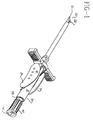
- FIG. 1 is a perspective view of the introducer needle assembly of this invention with a catheter introducer coaxially located thereover;
- FIG. 2 is a perspective view of the introducer needle assembly of this invention;
- FIG. 3 is a top plan view of the introducer needle assembly of this invention.
- FIG. 4 is a side elevation view of the introducer needle assembly of this invention; and
- FIG. 5 is a proximal end elevation view of the introducer needle assembly of this invention without the flow control plug.
- Although this invention is described as being an introducer needle assembly, it is to be understood that this invention is applicable to other types of needle assemblies such as spinal needles, guidewire introducer needles, through the needle introducers and needle assemblies for catheter introducers.
- Introducer needle assembly 10 includes a
needle 20 and aneedle hub 30 and aflow control plug 40 which all have a longitudinal axis A-A. -
Needle 20 includes a sharpdistal tip 21 and aproximal end 29. Sharpdistal tip 21 is in the form of a bevel 22 which includes adistal end 22a and aproximal end 22b.Proximal end 29 of needle is affixed to needlehub 30 by any standard mechanism such as by using an adhesive. Preferably a UV cured epoxy is used to bondneedle 20 toneedle hub 30. -
Needle hub 30 is formed from any strong, transparent polymer such as propionate. Themain body portion 31 ofneedle hub 30 has a generally tubular configuration and is hollow. This hollow interior defines theflashback chamber 32. In order to prevent blood from leaking out of theproximal end 33 ofneedle hub 30,flow control plug 40 is located in openproximal end 33.Flow control plug 40 may be formed from a porous low density polyethylene such as the material sold under the POREX trademark by Porex Materials Corporation. Alternatively,flow control plug 40 can be a plastic plug that fits into openproximal end 33 and has a hydrophobic membrane or any material that is impervious to blood but will allow air to flow through it placed over the openproximal end 41 offlow control plug 40. A hydrophobic membrane or other thin porous film material could be placed directly over openproximal end 33. - Located on opposite sides of
main body portion 31 are a pair offingergrips 34. Eachfingergrip 34 is connected tomain body portion 31 by any standard mechanism such as by using an adhesive or by ultrasonic welding. Alternatively,fingergrips 34 could be molded integrally withmain body portion 31. - Each
fingergrip 34 is connected tomain body portion 31 so that eachfingergrip 34 is about 180° apart from one another. In addition, eachfingergrip 34 defines a height H, see FIG. 5, that is substantially parallel to the height H of theother fingergrip 34. Preferably the center of gravity of eachfingergrip 34 is above longitudinal axis A-A ofmain body portion 31. As used herein, the terms "above" and "up" refer to the direction toward the top of FIG. 4 when the sheet is in the landscape orientation. This asymmetrical orientation offingergrips 34 facilitates gripping offingergrips 34 by the clinician. In addition, this configuration allows the clinician to insert introducer needle assembly 10 into a patient with a lower angle of attack. This facilitates successful insertion of introducer needle assembly 10 in the vein. - Each
fingergrip 34 has a generally elliptically shaped facingsurface 35 where the bottom portion has been removed to create aflat bottom 36. Theellipse forming fingergrips 34 should have a height to width ratio of between about 1:1 to about 1:4. Preferably theellipse forming fingergrips 34 has a major axis, i.e. width, of about 1 inch and a minor axis, i.e. height, of about 0.465 inches. Preferably the minor axis is about 0.376 inches whenflat bottom 36 is formed on eachfingergrip 34. The major axis of eachfingergrip 34 is the centerline of the ellipse beforeflat bottom 36 is formed. Thus, after flat bottom 36 is formed on eachfingergrip 34, the center of gravity of eachfingergrip 34 moves up away from the major axis of theellipse forming fingergrip 34. This results in introducer needle assembly 10 having a low profile. In addition, flat bottom 36 clearly indicates to the clinician the bottom of needle introducer assembly 10. An elliptical shape for facingsurface 35 is preferred because it has no corners and is aesthetically pleasing. However, other shapes such as a rectangle could be used for each facingsurface 35. - As seen in FIGS. 4 and 5,
needle 20 is connected toneedle hub 30 so that the opening into bevel 22 of sharpdistal tip 21 is facing up away fromflat bottom 36 offingergrips 34. In other words, needle 20 is affixed toneedle hub 30 such that a plane P defined by a line C extending betweendistal end 22a of bevel 22 andproximal end 22b of bevel 22 and longitidunal axis A-A is substantially parallel to the height H of eachfingergrip 34. This configuration allows the clinician intuitively to know that bevel 22 is in the proper orientation. Although plane P is preferably parallel to each height H, each height H may be at an angle of up to about 30 degrees in either direction from being parallel to plane P. - Each facing
surface 35 preferably has an arcuate surface over a major portion thereof and a plurality of bumps formed thereon to facilitate gripping by the clinician. Preferably the arcuate surface of facingsurface 35 defines an arc having a radius of about 1.185 inches, although a radius of between about 0.5 inches to about 3 inches would work. Alternatively, each facingsurface 35 could be flat. In addition, each facingsurface 35 could include other texturing thereon instead of a plurality of raised bumps. - Thus, it is seen that an introducer needle assembly is provided that facilitates use thereof with the needle bevel in the proper orientation without the need for the clinician to actually observe the needle bevel and that allows the clinician to easily maintain the needle bevel in the proper orientation during insertion into a patient.
Claims (8)
- A needle assembly having a longitudinal axis, comprising:a needle having a sharp distal tip, a proximal end and a bevel having a distal end and a proximal end;a needle hub having a proximal end and a distal end connected to the proximal end of the needle; andat least one fingergrip having a height and being located on the needle hub wherein the height is at an angle of up to about 30° to a plane defined by a line extending between the distal end of the bevel and the proximal end of the bevel and the longitudinal axis.
- The needle assembly of claim 1 wherein the fingergrip defines a center of gravity that is not aligned with the longitudinal axis.
- The needle assembly of claim 2 wherein the fingergrip has a substantially flat bottom.
- The needle assembly of claim 1 wherein the fingergrip has a generally elliptical configuration.
- The needle assembly of claim 4 wherein the fingergrip has a height to width ratio of between about. 1:1 to about 1:4.
- The needle assembly of claim 1 wherein the fingergrip has an arcuate face.
- The needle assembly of claim 6 wherein the arcuate face is an arc having a radius of between about 0.5 inches to about 3 inches.
- The needle assembly of claim 6 wherein the fingergrip has a plurality of bumps formed the arcuate face.
Applications Claiming Priority (2)
| Application Number | Priority Date | Filing Date | Title |
|---|---|---|---|
| US60909196A | 1996-02-29 | 1996-02-29 | |
| US609091 | 2000-06-30 |
Publications (2)
| Publication Number | Publication Date |
|---|---|
| EP0792659A2 true EP0792659A2 (en) | 1997-09-03 |
| EP0792659A3 EP0792659A3 (en) | 1998-02-11 |
Family
ID=24439323
Family Applications (1)
| Application Number | Title | Priority Date | Filing Date |
|---|---|---|---|
| EP97300945A Withdrawn EP0792659A3 (en) | 1996-02-29 | 1997-02-13 | Introducer needle assembly with orienting grip |
Country Status (3)
| Country | Link |
|---|---|
| EP (1) | EP0792659A3 (en) |
| JP (1) | JPH09239038A (en) |
| CA (1) | CA2198062A1 (en) |
Cited By (5)
| Publication number | Priority date | Publication date | Assignee | Title |
|---|---|---|---|---|
| WO2013032770A1 (en) * | 2011-08-31 | 2013-03-07 | Smiths Medical Asd, Inc. | Needle assembly |
| US9289555B2 (en) | 2010-10-01 | 2016-03-22 | Bracco Imaging S.P.A. | Finger-grip device for medical syringe or cartridge |
| WO2016164981A1 (en) * | 2015-04-16 | 2016-10-20 | X Tec Pty Ltd | A syringe |
| US10086151B2 (en) | 2012-08-06 | 2018-10-02 | Smiths Medical Asd, Inc. | Needle assembly |
| US10537683B2 (en) | 2016-11-03 | 2020-01-21 | Johnson & Johnson Surgical Vision, Inc. | Syringe finger grip |
Citations (5)
| Publication number | Priority date | Publication date | Assignee | Title |
|---|---|---|---|---|
| FR2215977A1 (en) * | 1973-02-07 | 1974-08-30 | Boehringer Sohn Ingelheim | |
| US4020835A (en) * | 1973-08-16 | 1977-05-03 | Boehringer Ingelheim Gmbh | Catheter placement assembly |
| US4392856A (en) * | 1981-10-23 | 1983-07-12 | Whitman Medical Corporation | Vascular puncture stabilizer fitting for facilitating withdrawal |
| US5186712A (en) * | 1991-08-23 | 1993-02-16 | Kansas Creative Devices, Inc. | Intravenous catheter launching device |
| US5489273A (en) * | 1994-10-07 | 1996-02-06 | Tfx Medical, Incorporated | Introducer device and methods of use thereof |
-
1997
- 1997-02-13 EP EP97300945A patent/EP0792659A3/en not_active Withdrawn
- 1997-02-20 CA CA 2198062 patent/CA2198062A1/en not_active Abandoned
- 1997-02-27 JP JP9043875A patent/JPH09239038A/en active Pending
Patent Citations (5)
| Publication number | Priority date | Publication date | Assignee | Title |
|---|---|---|---|---|
| FR2215977A1 (en) * | 1973-02-07 | 1974-08-30 | Boehringer Sohn Ingelheim | |
| US4020835A (en) * | 1973-08-16 | 1977-05-03 | Boehringer Ingelheim Gmbh | Catheter placement assembly |
| US4392856A (en) * | 1981-10-23 | 1983-07-12 | Whitman Medical Corporation | Vascular puncture stabilizer fitting for facilitating withdrawal |
| US5186712A (en) * | 1991-08-23 | 1993-02-16 | Kansas Creative Devices, Inc. | Intravenous catheter launching device |
| US5489273A (en) * | 1994-10-07 | 1996-02-06 | Tfx Medical, Incorporated | Introducer device and methods of use thereof |
Cited By (6)
| Publication number | Priority date | Publication date | Assignee | Title |
|---|---|---|---|---|
| US9289555B2 (en) | 2010-10-01 | 2016-03-22 | Bracco Imaging S.P.A. | Finger-grip device for medical syringe or cartridge |
| WO2013032770A1 (en) * | 2011-08-31 | 2013-03-07 | Smiths Medical Asd, Inc. | Needle assembly |
| US9861383B2 (en) | 2011-08-31 | 2018-01-09 | Smiths Medical Asd, Inc. | Needle assembly |
| US10086151B2 (en) | 2012-08-06 | 2018-10-02 | Smiths Medical Asd, Inc. | Needle assembly |
| WO2016164981A1 (en) * | 2015-04-16 | 2016-10-20 | X Tec Pty Ltd | A syringe |
| US10537683B2 (en) | 2016-11-03 | 2020-01-21 | Johnson & Johnson Surgical Vision, Inc. | Syringe finger grip |
Also Published As
| Publication number | Publication date |
|---|---|
| JPH09239038A (en) | 1997-09-16 |
| EP0792659A3 (en) | 1998-02-11 |
| CA2198062A1 (en) | 1997-08-29 |
Similar Documents
| Publication | Publication Date | Title |
|---|---|---|
| US4020835A (en) | Catheter placement assembly | |
| EP0317555B1 (en) | High flux threaded needle | |
| EP0610308B1 (en) | Arterial catheter | |
| US3630198A (en) | Catheter placement device | |
| US4445893A (en) | Infusion apparatus | |
| US4880412A (en) | Tube insertion apparatus | |
| EP0932369B1 (en) | Catheter guide wire introducing device and method | |
| US4349023A (en) | Epidural needle catheter and adapter | |
| US5098395A (en) | Medical connector | |
| EP0158697B1 (en) | Dialysis needle | |
| US5267971A (en) | Catheter introducer with notched needle | |
| EP1231971B1 (en) | Guide for surgical device | |
| EP0391511B1 (en) | Suction tube for use in surgical operation, particularly for liposuction | |
| EP0486498B1 (en) | A catheter introduction syringe | |
| US6953448B2 (en) | Cantilever push tab for an intravenous medical device | |
| US5630802A (en) | Device for introducing a catheter into a body cavity | |
| US4713057A (en) | Mechanical assist device for inserting catheters | |
| US4828549A (en) | Over-the-needle catheter assembly | |
| EP0155331A1 (en) | Apparatus for providing an opening into a body cavity or hollow viscus | |
| EP0440479A2 (en) | Catheter with controlled valve | |
| GB2065479A (en) | Devices for introducing a catheter or a probe into a blood vessel | |
| US5312376A (en) | Catheter with clear needle shaft | |
| US3920013A (en) | Subclavian vena puncture devices | |
| EP0792659A2 (en) | Introducer needle assembly with orienting grip | |
| US4493708A (en) | Intravascular catheter assembly |
Legal Events
| Date | Code | Title | Description |
|---|---|---|---|
| PUAI | Public reference made under article 153(3) epc to a published international application that has entered the european phase |
Free format text: ORIGINAL CODE: 0009012 |
|
| AK | Designated contracting states |
Kind code of ref document: A2 Designated state(s): DE ES FR GB IT |
|
| PUAL | Search report despatched |
Free format text: ORIGINAL CODE: 0009013 |
|
| AK | Designated contracting states |
Kind code of ref document: A3 Designated state(s): DE ES FR GB IT |
|
| STAA | Information on the status of an ep patent application or granted ep patent |
Free format text: STATUS: THE APPLICATION IS DEEMED TO BE WITHDRAWN |
|
| 18D | Application deemed to be withdrawn |
Effective date: 19980812 |