EP0794885B1 - System zur fahrstabilitätsregelung - Google Patents
System zur fahrstabilitätsregelung Download PDFInfo
- Publication number
- EP0794885B1 EP0794885B1 EP95941020A EP95941020A EP0794885B1 EP 0794885 B1 EP0794885 B1 EP 0794885B1 EP 95941020 A EP95941020 A EP 95941020A EP 95941020 A EP95941020 A EP 95941020A EP 0794885 B1 EP0794885 B1 EP 0794885B1
- Authority
- EP
- European Patent Office
- Prior art keywords
- vehicle
- pressure
- wheel
- control
- yaw rate
- Prior art date
- Legal status (The legal status is an assumption and is not a legal conclusion. Google has not performed a legal analysis and makes no representation as to the accuracy of the status listed.)
- Expired - Lifetime
Links
- 230000001133 acceleration Effects 0.000 claims description 65
- 230000002441 reversible effect Effects 0.000 claims description 14
- 230000004913 activation Effects 0.000 claims description 11
- 238000004364 calculation method Methods 0.000 description 65
- 238000000034 method Methods 0.000 description 36
- 230000008859 change Effects 0.000 description 35
- 238000009826 distribution Methods 0.000 description 35
- 238000012937 correction Methods 0.000 description 30
- 239000010432 diamond Substances 0.000 description 29
- 229910003460 diamond Inorganic materials 0.000 description 28
- 230000006399 behavior Effects 0.000 description 27
- 239000013598 vector Substances 0.000 description 25
- 238000005259 measurement Methods 0.000 description 21
- 238000010586 diagram Methods 0.000 description 19
- 238000001514 detection method Methods 0.000 description 18
- 230000009467 reduction Effects 0.000 description 18
- 230000010354 integration Effects 0.000 description 16
- 230000005484 gravity Effects 0.000 description 15
- 230000033228 biological regulation Effects 0.000 description 14
- 230000006870 function Effects 0.000 description 11
- 230000008569 process Effects 0.000 description 11
- 239000011159 matrix material Substances 0.000 description 10
- 230000007423 decrease Effects 0.000 description 8
- 230000002829 reductive effect Effects 0.000 description 8
- 238000011156 evaluation Methods 0.000 description 7
- 230000001105 regulatory effect Effects 0.000 description 7
- 238000013459 approach Methods 0.000 description 6
- 238000004422 calculation algorithm Methods 0.000 description 6
- 230000008901 benefit Effects 0.000 description 5
- 230000003111 delayed effect Effects 0.000 description 5
- 230000007935 neutral effect Effects 0.000 description 5
- 238000001914 filtration Methods 0.000 description 4
- 238000007726 management method Methods 0.000 description 4
- 230000005540 biological transmission Effects 0.000 description 3
- 238000006243 chemical reaction Methods 0.000 description 3
- 230000001276 controlling effect Effects 0.000 description 3
- 230000001419 dependent effect Effects 0.000 description 3
- 238000009795 derivation Methods 0.000 description 3
- 230000000694 effects Effects 0.000 description 3
- 239000000654 additive Substances 0.000 description 2
- 230000000996 additive effect Effects 0.000 description 2
- 230000000903 blocking effect Effects 0.000 description 2
- 230000004048 modification Effects 0.000 description 2
- 238000012986 modification Methods 0.000 description 2
- 238000005096 rolling process Methods 0.000 description 2
- 238000012360 testing method Methods 0.000 description 2
- 230000007704 transition Effects 0.000 description 2
- 230000028838 turning behavior Effects 0.000 description 2
- ORILYTVJVMAKLC-UHFFFAOYSA-N Adamantane Natural products C1C(C2)CC3CC1CC2C3 ORILYTVJVMAKLC-UHFFFAOYSA-N 0.000 description 1
- 101100022430 Arabidopsis thaliana MYB101 gene Proteins 0.000 description 1
- 230000015572 biosynthetic process Effects 0.000 description 1
- 238000011217 control strategy Methods 0.000 description 1
- 230000036461 convulsion Effects 0.000 description 1
- 238000013461 design Methods 0.000 description 1
- 238000011161 development Methods 0.000 description 1
- 230000018109 developmental process Effects 0.000 description 1
- 230000004069 differentiation Effects 0.000 description 1
- 238000006073 displacement reaction Methods 0.000 description 1
- 238000005516 engineering process Methods 0.000 description 1
- 230000002349 favourable effect Effects 0.000 description 1
- 239000012530 fluid Substances 0.000 description 1
- 230000012447 hatching Effects 0.000 description 1
- 230000000670 limiting effect Effects 0.000 description 1
- 238000012886 linear function Methods 0.000 description 1
- 238000012423 maintenance Methods 0.000 description 1
- KFOPKOFKGJJEBW-ZSSYTAEJSA-N methyl 2-[(1s,7r,8s,9s,10r,13r,14s,17r)-1,7-dihydroxy-10,13-dimethyl-3-oxo-1,2,6,7,8,9,11,12,14,15,16,17-dodecahydrocyclopenta[a]phenanthren-17-yl]acetate Chemical compound C([C@H]1O)C2=CC(=O)C[C@H](O)[C@]2(C)[C@@H]2[C@@H]1[C@@H]1CC[C@H](CC(=O)OC)[C@@]1(C)CC2 KFOPKOFKGJJEBW-ZSSYTAEJSA-N 0.000 description 1
- 238000005457 optimization Methods 0.000 description 1
- 230000010355 oscillation Effects 0.000 description 1
- 230000010363 phase shift Effects 0.000 description 1
- 230000002265 prevention Effects 0.000 description 1
- 238000012545 processing Methods 0.000 description 1
- 230000004044 response Effects 0.000 description 1
- 230000000717 retained effect Effects 0.000 description 1
- 230000035945 sensitivity Effects 0.000 description 1
- 238000009987 spinning Methods 0.000 description 1
- 230000006641 stabilisation Effects 0.000 description 1
- 238000011105 stabilization Methods 0.000 description 1
- 230000003068 static effect Effects 0.000 description 1
- 238000006467 substitution reaction Methods 0.000 description 1
- 239000000725 suspension Substances 0.000 description 1
- 230000009182 swimming Effects 0.000 description 1
- 230000002123 temporal effect Effects 0.000 description 1
- 230000009466 transformation Effects 0.000 description 1
Images


Classifications
-
- B—PERFORMING OPERATIONS; TRANSPORTING
- B60—VEHICLES IN GENERAL
- B60T—VEHICLE BRAKE CONTROL SYSTEMS OR PARTS THEREOF; BRAKE CONTROL SYSTEMS OR PARTS THEREOF, IN GENERAL; ARRANGEMENT OF BRAKING ELEMENTS ON VEHICLES IN GENERAL; PORTABLE DEVICES FOR PREVENTING UNWANTED MOVEMENT OF VEHICLES; VEHICLE MODIFICATIONS TO FACILITATE COOLING OF BRAKES
- B60T8/00—Arrangements for adjusting wheel-braking force to meet varying vehicular or ground-surface conditions, e.g. limiting or varying distribution of braking force
- B60T8/17—Using electrical or electronic regulation means to control braking
- B60T8/1755—Brake regulation specially adapted to control the stability of the vehicle, e.g. taking into account yaw rate or transverse acceleration in a curve
- B60T8/17551—Brake regulation specially adapted to control the stability of the vehicle, e.g. taking into account yaw rate or transverse acceleration in a curve determining control parameters related to vehicle stability used in the regulation, e.g. by calculations involving measured or detected parameters
-
- B—PERFORMING OPERATIONS; TRANSPORTING
- B60—VEHICLES IN GENERAL
- B60T—VEHICLE BRAKE CONTROL SYSTEMS OR PARTS THEREOF; BRAKE CONTROL SYSTEMS OR PARTS THEREOF, IN GENERAL; ARRANGEMENT OF BRAKING ELEMENTS ON VEHICLES IN GENERAL; PORTABLE DEVICES FOR PREVENTING UNWANTED MOVEMENT OF VEHICLES; VEHICLE MODIFICATIONS TO FACILITATE COOLING OF BRAKES
- B60T8/00—Arrangements for adjusting wheel-braking force to meet varying vehicular or ground-surface conditions, e.g. limiting or varying distribution of braking force
- B60T8/17—Using electrical or electronic regulation means to control braking
- B60T8/1755—Brake regulation specially adapted to control the stability of the vehicle, e.g. taking into account yaw rate or transverse acceleration in a curve
-
- B—PERFORMING OPERATIONS; TRANSPORTING
- B60—VEHICLES IN GENERAL
- B60W—CONJOINT CONTROL OF VEHICLE SUB-UNITS OF DIFFERENT TYPE OR DIFFERENT FUNCTION; CONTROL SYSTEMS SPECIALLY ADAPTED FOR HYBRID VEHICLES; ROAD VEHICLE DRIVE CONTROL SYSTEMS FOR PURPOSES NOT RELATED TO THE CONTROL OF A PARTICULAR SUB-UNIT
- B60W10/00—Conjoint control of vehicle sub-units of different type or different function
- B60W10/18—Conjoint control of vehicle sub-units of different type or different function including control of braking systems
- B60W10/184—Conjoint control of vehicle sub-units of different type or different function including control of braking systems with wheel brakes
-
- B—PERFORMING OPERATIONS; TRANSPORTING
- B60—VEHICLES IN GENERAL
- B60W—CONJOINT CONTROL OF VEHICLE SUB-UNITS OF DIFFERENT TYPE OR DIFFERENT FUNCTION; CONTROL SYSTEMS SPECIALLY ADAPTED FOR HYBRID VEHICLES; ROAD VEHICLE DRIVE CONTROL SYSTEMS FOR PURPOSES NOT RELATED TO THE CONTROL OF A PARTICULAR SUB-UNIT
- B60W30/00—Purposes of road vehicle drive control systems not related to the control of a particular sub-unit, e.g. of systems using conjoint control of vehicle sub-units, or advanced driver assistance systems for ensuring comfort, stability and safety or drive control systems for propelling or retarding the vehicle
- B60W30/02—Control of vehicle driving stability
-
- B—PERFORMING OPERATIONS; TRANSPORTING
- B60—VEHICLES IN GENERAL
- B60W—CONJOINT CONTROL OF VEHICLE SUB-UNITS OF DIFFERENT TYPE OR DIFFERENT FUNCTION; CONTROL SYSTEMS SPECIALLY ADAPTED FOR HYBRID VEHICLES; ROAD VEHICLE DRIVE CONTROL SYSTEMS FOR PURPOSES NOT RELATED TO THE CONTROL OF A PARTICULAR SUB-UNIT
- B60W40/00—Estimation or calculation of non-directly measurable driving parameters for road vehicle drive control systems not related to the control of a particular sub unit, e.g. by using mathematical models
- B60W40/02—Estimation or calculation of non-directly measurable driving parameters for road vehicle drive control systems not related to the control of a particular sub unit, e.g. by using mathematical models related to ambient conditions
- B60W40/06—Road conditions
- B60W40/064—Degree of grip
-
- B—PERFORMING OPERATIONS; TRANSPORTING
- B60—VEHICLES IN GENERAL
- B60G—VEHICLE SUSPENSION ARRANGEMENTS
- B60G2400/00—Indexing codes relating to detected, measured or calculated conditions or factors
- B60G2400/10—Acceleration; Deceleration
- B60G2400/104—Acceleration; Deceleration lateral or transversal with regard to vehicle
- B60G2400/1042—Acceleration; Deceleration lateral or transversal with regard to vehicle using at least two sensors
-
- B—PERFORMING OPERATIONS; TRANSPORTING
- B60—VEHICLES IN GENERAL
- B60T—VEHICLE BRAKE CONTROL SYSTEMS OR PARTS THEREOF; BRAKE CONTROL SYSTEMS OR PARTS THEREOF, IN GENERAL; ARRANGEMENT OF BRAKING ELEMENTS ON VEHICLES IN GENERAL; PORTABLE DEVICES FOR PREVENTING UNWANTED MOVEMENT OF VEHICLES; VEHICLE MODIFICATIONS TO FACILITATE COOLING OF BRAKES
- B60T2210/00—Detection or estimation of road or environment conditions; Detection or estimation of road shapes
- B60T2210/10—Detection or estimation of road conditions
- B60T2210/12—Friction
-
- B—PERFORMING OPERATIONS; TRANSPORTING
- B60—VEHICLES IN GENERAL
- B60T—VEHICLE BRAKE CONTROL SYSTEMS OR PARTS THEREOF; BRAKE CONTROL SYSTEMS OR PARTS THEREOF, IN GENERAL; ARRANGEMENT OF BRAKING ELEMENTS ON VEHICLES IN GENERAL; PORTABLE DEVICES FOR PREVENTING UNWANTED MOVEMENT OF VEHICLES; VEHICLE MODIFICATIONS TO FACILITATE COOLING OF BRAKES
- B60T2230/00—Monitoring, detecting special vehicle behaviour; Counteracting thereof
- B60T2230/02—Side slip angle, attitude angle, floating angle, drift angle
-
- B—PERFORMING OPERATIONS; TRANSPORTING
- B60—VEHICLES IN GENERAL
- B60T—VEHICLE BRAKE CONTROL SYSTEMS OR PARTS THEREOF; BRAKE CONTROL SYSTEMS OR PARTS THEREOF, IN GENERAL; ARRANGEMENT OF BRAKING ELEMENTS ON VEHICLES IN GENERAL; PORTABLE DEVICES FOR PREVENTING UNWANTED MOVEMENT OF VEHICLES; VEHICLE MODIFICATIONS TO FACILITATE COOLING OF BRAKES
- B60T2270/00—Further aspects of brake control systems not otherwise provided for
- B60T2270/30—ESP control system
- B60T2270/313—ESP control system with less than three sensors (yaw rate, steering angle, lateral acceleration)
-
- B—PERFORMING OPERATIONS; TRANSPORTING
- B60—VEHICLES IN GENERAL
- B60W—CONJOINT CONTROL OF VEHICLE SUB-UNITS OF DIFFERENT TYPE OR DIFFERENT FUNCTION; CONTROL SYSTEMS SPECIALLY ADAPTED FOR HYBRID VEHICLES; ROAD VEHICLE DRIVE CONTROL SYSTEMS FOR PURPOSES NOT RELATED TO THE CONTROL OF A PARTICULAR SUB-UNIT
- B60W2422/00—Indexing codes relating to the special location or mounting of sensors
- B60W2422/95—Measuring the same parameter at multiple locations of the vehicle
-
- B—PERFORMING OPERATIONS; TRANSPORTING
- B60—VEHICLES IN GENERAL
- B60W—CONJOINT CONTROL OF VEHICLE SUB-UNITS OF DIFFERENT TYPE OR DIFFERENT FUNCTION; CONTROL SYSTEMS SPECIALLY ADAPTED FOR HYBRID VEHICLES; ROAD VEHICLE DRIVE CONTROL SYSTEMS FOR PURPOSES NOT RELATED TO THE CONTROL OF A PARTICULAR SUB-UNIT
- B60W2520/00—Input parameters relating to overall vehicle dynamics
- B60W2520/12—Lateral speed
- B60W2520/125—Lateral acceleration
-
- B—PERFORMING OPERATIONS; TRANSPORTING
- B60—VEHICLES IN GENERAL
- B60W—CONJOINT CONTROL OF VEHICLE SUB-UNITS OF DIFFERENT TYPE OR DIFFERENT FUNCTION; CONTROL SYSTEMS SPECIALLY ADAPTED FOR HYBRID VEHICLES; ROAD VEHICLE DRIVE CONTROL SYSTEMS FOR PURPOSES NOT RELATED TO THE CONTROL OF A PARTICULAR SUB-UNIT
- B60W2520/00—Input parameters relating to overall vehicle dynamics
- B60W2520/14—Yaw
-
- B—PERFORMING OPERATIONS; TRANSPORTING
- B60—VEHICLES IN GENERAL
- B60W—CONJOINT CONTROL OF VEHICLE SUB-UNITS OF DIFFERENT TYPE OR DIFFERENT FUNCTION; CONTROL SYSTEMS SPECIALLY ADAPTED FOR HYBRID VEHICLES; ROAD VEHICLE DRIVE CONTROL SYSTEMS FOR PURPOSES NOT RELATED TO THE CONTROL OF A PARTICULAR SUB-UNIT
- B60W2520/00—Input parameters relating to overall vehicle dynamics
- B60W2520/20—Sideslip angle
-
- B—PERFORMING OPERATIONS; TRANSPORTING
- B60—VEHICLES IN GENERAL
- B60W—CONJOINT CONTROL OF VEHICLE SUB-UNITS OF DIFFERENT TYPE OR DIFFERENT FUNCTION; CONTROL SYSTEMS SPECIALLY ADAPTED FOR HYBRID VEHICLES; ROAD VEHICLE DRIVE CONTROL SYSTEMS FOR PURPOSES NOT RELATED TO THE CONTROL OF A PARTICULAR SUB-UNIT
- B60W2720/00—Output or target parameters relating to overall vehicle dynamics
- B60W2720/14—Yaw
-
- B—PERFORMING OPERATIONS; TRANSPORTING
- B60—VEHICLES IN GENERAL
- B60W—CONJOINT CONTROL OF VEHICLE SUB-UNITS OF DIFFERENT TYPE OR DIFFERENT FUNCTION; CONTROL SYSTEMS SPECIALLY ADAPTED FOR HYBRID VEHICLES; ROAD VEHICLE DRIVE CONTROL SYSTEMS FOR PURPOSES NOT RELATED TO THE CONTROL OF A PARTICULAR SUB-UNIT
- B60W2720/00—Output or target parameters relating to overall vehicle dynamics
- B60W2720/30—Wheel torque
Definitions
- FSR driving stability control
- a vehicle is a motor vehicle meant with four wheels, which with one hydraulic brake system is equipped.
- the hydraulic brake system can be operated by means of a pedal Master cylinder a brake pressure can be built up by the driver.
- Each wheel has a brake, which one Inlet valve and an outlet valve is assigned.
- About the Intake valves are in the wheel brakes with the master cylinder Connection while the exhaust valves are depressurized Guide the container or low-pressure accumulator.
- an auxiliary pressure source which is also independent from the position of the brake pedal into the Can build wheel brakes.
- the intake and exhaust valves are electromagnetic for pressure control in the wheel brakes actuatable.
- Speed sensors there are four for recording dynamic driving conditions Speed sensors, one per wheel, one yaw rate sensor, a lateral accelerometer and at least one Pressure sensor for the brake pressure generated by the brake pedal available.
- the pressure sensor can also be replaced by a pedal travel or pedal dynamometer if the Auxiliary pressure source is arranged such that a driver built up brake pressure from that of the auxiliary pressure source not is distinguishable.
- a critical situation here is an unstable driving condition, in which, in extreme cases, the vehicle meets the requirements of the Driver does not follow.
- the traction control and the electronic brake force distribution in primarily the longitudinal slip of the tires on the road is important, flow into the yaw moment control (GMR) other sizes, for example the yaw rate ⁇ ⁇ .
- GMR yaw moment control
- the float angle ⁇ and the yaw rate ⁇ ⁇ represent the state variables of the system.
- the input variable acting on the vehicle represents the steering angle ⁇ , as a result of which the vehicle obtains the yaw rate ⁇ ⁇ as the output variable.
- c h and c v stand for the resulting stiffness from tire, wheel suspension and steering elasticity on the rear and front axles.
- l h and l v represent the distances between the rear axle and the front axle from the center of gravity.
- ⁇ is the yaw moment of inertia of the vehicle, i.e. the moment of inertia of the vehicle about its vertical axis.
- DE-40 30 704 A1 describes a two-track model for one Vehicle proposed, which one in its accuracy Single track model is superior. Here too form the Yaw rate ⁇ ⁇ and the slip angle ⁇ die Condition sizes. When using a two-track model However, it should be noted that an enormous computing capacity is needed to get one in a sufficiently short time To be able to carry out control intervention.
- a target yaw rate is always calculated assuming forward travel. Is that Vehicle but actually in a reverse drive Curve, is its measured target yaw rate exactly opposite and gives because of their great Deviation from the target yaw rate causes Assumption that the vehicle is in an unstable Driving condition.
- the object of the present invention is therein a device for regulating the Yaw moment of a vehicle according to the top mountain of the To create claim 1, in which when reversing such fallacies are excluded.
- the invention therefore consists of yaw moment control easy to turn off when situation detection Reverses.
- the vehicle forms the so-called controlled system:
- the vehicle 1 forms the so-called controlled system: the driver brake pressure P driver and steering angle ⁇ given by the driver act on the vehicle 1.
- the driver brake pressure P driver and steering angle ⁇ given by the driver act on the vehicle 1.
- the resulting motor torque M motist , lateral acceleration a transverse , yaw rate ⁇ ⁇ , wheel speeds and hydraulic signals such as wheel brake pressures are measured.
- the FSR system has four electronic controllers 7, 8, 9 and 10, each of which is assigned to the anti-lock braking system ABS, the traction control system ASR, the electronic brake force distribution EBV and the yaw moment control GMR.
- the electronic controllers for ABS 7, ASR 8 and EBV 9 can continue to correspond to the state of the art.
- the wheel speeds are fed to the controllers for the anti-lock braking system 7, the traction control system 8 and the electronic braking force distribution 9.
- the controller 8 of the traction control system additionally receives data about the prevailing engine torque, the actual engine torque M Motist . This information also goes to the controller 10 for yaw moment control GMR. It also receives data from sensors about lateral acceleration a transverse and the yaw rate winkel ⁇ of the vehicle. Since a vehicle reference speed v Ref is determined in any case in the controller 7 of the ABS via the individual wheel speeds of the vehicle wheels, on the basis of which an excessive braking slip of one of the wheels can be determined, such a reference speed does not have to be calculated in the GMR controller 10, but is calculated by the ABS controller 7 taken over.
- the vehicle reference speed is calculated or whether a separate calculation is made for yaw moment control only makes a small difference for the course of the yaw moment control.
- the value for this could also be determined in the ABS controller 7 and passed on to the GMR controller 10. This applies only to a limited extent to a determination of the road coefficient of friction ⁇ , since a more precisely determined coefficient of friction is desirable for yaw moment control than is determined for the anti-lock system.
- All four electronic controllers of the FSR i.e. the controllers for GMR 10, ABS 7, ASR 8 and EBV 9, work in parallel and independently of each other based on their own control strategies, brake pressure specifications P GMR, P ABS, P ASR, P EBV for the individual wheels.
- the ASR controller 8 and the GMR controller 10 simultaneously calculate specifications M ASR and M StellM for the engine torque.
- the pressure specifications p GMR of the GMR controller 10 for the individual wheel brake pressures are determined as follows:
- the GMR controller 10 first calculates an additional yaw moment M G , which leads to the stabilization of the driving state within a curve when it is generated by appropriate brake actuation.
- This M G is fed to a distribution logic 2, which could also be represented as part of the GMR controller 10.
- the distribution logic 2 calculates yaw moment control brake pressures P GMR for the wheel brakes from the predetermined yaw moment MG and from the desired driver brake pressure, which can be very different individually for the individual wheels.
- These yaw moment control brake pressures P GMR like the pressure specifications calculated by the other controllers 7, 8 and 9 for ABS, TCS and EBV for function optimization, are fed to a priority circuit 3 for the wheel brake pressures.
- a priority circuit 3 determined taking into account the driver's request Sollraddrücke p for optimum stability.
- These setpoint pressures can either correspond to the pressure specifications of a single one of these four regulators or can represent an overlay.
- the engine torque is handled in a similar way to the wheel brake pressures. While ABS and EBV only act on the wheel brakes, GMR and ASR also intervene in the engine torque.
- the specifications M StellM and M ASR for the engine torque which are calculated separately in the GMR controller 10 and in the ASR controller 8, are again evaluated in a priority circuit 4 and superimposed on a setpoint torque.
- this target torque M target can just as well correspond to the calculated specification of one of the two controllers.
- driving stability control can now be carried out by braking and engaging the engine.
- hydraulic signals or values that reflect the actual wheel brake pressure flow into the pressure controller 5.
- the pressure controller 5 generates valve signals which are emitted to the control valves of the individual wheel brakes in the vehicle 1.
- the engine management system 6 controls in accordance with M to the drive motor of the vehicle, which in turn is a modified engine torque is generated. This then results in new input variables for the four electronic controllers 7, 8, 9 and 10 of the FSR system.
- FIG. 2 shows in a block diagram how the additional yaw moment M G for the distribution logic 2 is determined within the GMR controller 10.
- the steering angle ⁇ the vehicle reference speed v Ref from the ABS controller 7, the measured lateral acceleration a q and the measured yaw angle speed ⁇ ⁇ Mess are used as input variables.
- the vehicle reference speed vRef passes through a filter 17, which sets a constant value above zero at low speeds, so that the denominator of a fraction does not become zero in further calculations.
- the unfiltered value of v Ref is only fed to an activation logic 11, which recognizes vehicle standstill.
- This direct detection of the vehicle reference speed v Ref by the activation logic 11 can also be omitted if it is assumed that the vehicle is at a standstill when the filtered vehicle reference speed V RefFil assumes its constant minimum value.
- a vehicle reference model 12 is stored in the GMR controller, which uses the steering angle ⁇ , the filtered vehicle reference speed vRefFil and the measured yaw rate ⁇ ⁇ measurement to calculate a specification for a change in the yaw rate ⁇ ⁇ .
- the road surface friction coefficient ⁇ needed in a friction coefficient and situation detection 13 is calculated as an estimate ⁇ .
- the latter can also be used for the coefficient of friction. Or but in ABS controller 7, the coefficient of friction calculated in GMR controller 10 accepted.
- the friction value and situation detection 13 uses the filtered reference speed v RefFil , the measured vehicle lateral acceleration a transverse , the measured yaw rate embassy ⁇ measurement , and the steering angle ⁇ for their calculations.
- the situation detection distinguishes different cases such as driving straight ahead, cornering, reversing and vehicle standstill.
- Vehicle standstill is assumed when the filtered vehicle reference speed v RefFil assumes its constant minimum value. Instead of the unfiltered vehicle reference speed, this information can also be supplied to the activation logic 11 for the detection of a vehicle standstill.
- To detect the backward drive use is made of the fact that, given the steering angle ⁇ , the yaw rate ⁇ ⁇ is oriented in the opposite direction to that when driving forward.
- the measured yaw speed ⁇ ⁇ measurement is with the predetermined reference model of the vehicle 12 target yaw rate ⁇ ⁇ soll. If the signs are always opposite and this also applies to the time derivatives of the two curves, then there is a backward drive, because ⁇ ⁇ should always be calculated for forward drive because common speed sensors do not record any information about the direction of wheel rotation.
- a kinematic slip angle speed determination is carried out.
- the calculated value of the slip angle speed passes through a first-order low-pass filter 15, which is an estimate for the slip angle speed to the activation logic 11 and to a program 16 for implementing the yaw moment control law.
- the program 16 also uses the change specifications ⁇ ⁇ for the yaw angular velocity, which is represented as the difference between the measured yaw angular velocity ⁇ ⁇ Mess and the target yaw angular velocity ⁇ ⁇ soll calculated on the basis of the vehicle reference model 12. From this, the additional yaw moment M G for the vehicle is determined, which is to be conveyed via the brake pressures.
- the program 16 works continuously in order to keep the control variables current ready to go. Whether these actuating torques, however the distribution logic 2 shown in Fig. 1 passed on depends on the activation logic 11.
- the activation logic 11 not only receives the value of the unfiltered vehicle reference speed v Ref and, as described, that of the slip angle speed , but also the amount
- the measured lateral acceleration a transverse is above the threshold value a qermin , but in diamond 55 it is recognized in the next step that the steering angle ⁇ is smaller than a threshold value ⁇ min .
- the measured lateral acceleration a transverse is a measurement error that results from the fact that lateral accelerometers are usually fixedly mounted in the vehicle's transverse axis and incline with the vehicle when the road is inclined sideways, so that a lateral acceleration is displayed that is actually not present.
- the size of the longitudinal acceleration a long is considered in diamond 59. If the amount is smaller than a threshold value a longmin , constant straight-ahead travel is assumed. If, however, the amount of the longitudinal acceleration a long is greater than this threshold value, diamond 60 distinguishes between positive and negative longitudinal acceleration. If the value of a long is above the threshold value a longmin , the vehicle is accelerating straight ahead, i.e. situation ⁇ 2>. If the value of a long is below the threshold value a longmin , this means nothing else than that there is negative longitudinal acceleration , i.e. a delayed straight-ahead drive , situation ⁇ 3>.
- diamond 56 queries whether the vehicle is now reversing.
- the detection of a reverse drive is only necessary at this point, since when driving straight ahead the yaw rate ⁇ ⁇ hardly differs from zero anyway and therefore a control intervention is not carried out. Only when a cornering is detected, in which the yaw moment control itself becomes active, must a reverse travel be excluded with certainty. This is not possible due to the signals from the wheel speed sensors alone, since such sensors only pass on the speed in terms of amount, without allowing conclusions to be drawn about the direction of travel.
- the situation ⁇ 6> is as described before, determined by comparing the measured yaw rate ⁇ ⁇ measurement with the determined in the vehicle reference model 12 target yaw rate ⁇ ⁇ should be compared. If the signs are opposite and this also applies to the time derivatives of the two quantities, the yaw rate accelerations and the vehicle is in a backward bend. The signs of the yaw angle accelerations are therefore compared so that it can be ruled out that the opposite signs of the yaw angle velocities do not only result from a phase shift which is caused by the time-delayed calculation of the target values.
- the longitudinal acceleration a long can be determined in various ways. It can be determined, for example, from the reference speed v Ref provided by the ABS controller 7, it having to be taken into account that such a reference speed v Ref can deviate from the actual vehicle speed during an ABS intervention. A correction of v Ref is therefore appropriate for an ABS case.
- the longitudinal acceleration a long can under certain circumstances also be taken over directly from the ABS controller if such a calculation takes place there.
- the situation detection according to Fig. 3 is constantly new drive through, the last determined situation being saved remains and is available in diamond 53.
- the yaw moment control responds on the basis of an instantaneous driving situation, it can be assumed that the vehicle is at least in the vicinity of the limit range for unstable driving situations. It is thus possible to deduce the current road surface friction value by considering the current measured variables on the vehicle.
- the friction coefficient then determined as it enters the control provides the basis for the limitation of the desired yaw rate ⁇ ⁇ to in the course, and thus also for the passed to the GMR control law 16 control difference for the yaw angular velocity ⁇ ⁇ .
- an internal coefficient of friction ⁇ and int is first calculated from the measured transverse acceleration a transverse and a calculated value for the longitudinal acceleration a long , which, assuming that a full use of the frictional connection exists, corresponds to the instantaneous coefficient of friction.
- the internal coefficient of friction ⁇ and int is assigned a higher coefficient of friction ⁇ and by means of a table, a characteristic curve or a constant factor. This coefficient of friction ⁇ and is then fed to the control.
- a road friction coefficient adapted to the target yaw rate ⁇ ⁇ is to be expected and improve regulation.
- An update of the coefficient of friction can be omitted if the time derivative of the coefficient of friction ⁇ and so is negative and the amount of the time derivative of the steering angle ⁇ , ie
- Step 62 includes the situation detection according to FIG. 3.
- the detected driving situation is later important for the update phase in step 74.
- step 68 the reg old parameter is set to 1 for step 65.
- the counting parameter T ⁇ is set to 1 in accordance with the fact that the first determination of the coefficient of friction of the internal coefficient of friction ⁇ and int has been carried out.
- step 69 an assignment of an estimated coefficient of friction ⁇ and to the calculated internal coefficient of friction ⁇ and int takes place . This is done on the assumption that the existing acceleration components are not yet based on full adhesion utilization. The estimated coefficient of friction ⁇ and is therefore usually between the determined internal coefficient of friction ⁇ and int and 1. This concludes the determination of the coefficient of friction.
- the parameter reg old is reset to 0 for the control (75).
- step 78 The criteria for an update of the internal coefficient of friction ⁇ and int after step 74 are shown in FIG. 5. Based on the specification in field 77 that the internal coefficient of friction ⁇ and int is to be updated, the time derivatives of the previously formed estimated coefficient of friction ⁇ and or ⁇ and int as well as the steering angle ⁇ are formed in step 78.
- Step 78 If it is then recognized in diamond 79 that the vehicle is neither is still driving straight ahead, so that's one of the situations ⁇ 6> to ⁇ 9> is present, the results are from Step 78 evaluated in step 80. Only if - how already explained - a falling coefficient of friction does not arise a steering maneuver is due, a coefficient of friction is determined performed. No coefficient of friction update, if either the vehicle turns straight ahead - forward or backward - or when the vehicle is stationary or a decrease in the estimated coefficient of friction ⁇ and a steering maneuver is due.
- a measure of the stability of a driving state is the predominant one Float angle ⁇ and its time derivative, the float angular velocity ⁇ ⁇ . The determination these values are explained below.
- the kinematic ⁇ ⁇ determination 14 contains nothing else, than that - detached from any vehicle models - the Floating angle velocity ⁇ ⁇ from measured or from measured values calculated values as follows purely physical considerations are determined:
- the acceleration a transverse to the center of gravity transverse to the longitudinal axis in the plane of movement is measured.
- the center of gravity of the vehicle moves with the speed vector v relative to an inertial system:
- ⁇ denotes the yaw angle and ⁇ the float angle.
- the acceleration vector a is derived from time t as:
- the slip angle velocity ⁇ ⁇ can now be calculated according to the differential equation above.
- the yaw angular velocity ⁇ ⁇ , the scalar vehicle speed v and their time derivative V ⁇ are used as the measured variable.
- a simplification results if the last term is generally neglected, so that no ⁇ has to be determined.
- the proposed method has the advantage that the Float angle velocity ⁇ ⁇ directly from the sensor signals is derived and thus also in the nonlinear range of Lateral dynamics can be determined.
- FIG. 6 shows how such a combination of a kinematic determination of the slip angle velocity ⁇ ⁇ based on an observer model can be designed, which can be inserted instead of the block 18 shown in broken lines in FIG. 2.
- the steering angle ⁇ also flows as an input variable, as indicated by a dashed arrow.
- an observer vehicle model 84 is used here to determine the driving state.
- the observer vehicle model 84 like the vehicle reference model 12 for determining the yaw rate — receives the steering angle ⁇ .
- the filtered vehicle reference speed v RefFil is used as a parameter.
- the measurable output variables lateral acceleration a transverse and yaw angular velocity ⁇ ⁇ measurement are required for the kinematic ⁇ ⁇ determination 83, but not for the observer vehicle model 84, which in principle creates these variables itself.
- Y which in the simplest case is identical to the additional yaw moment calculated by the GMR control law, represents the changes in vehicle behavior that are caused by a control intervention. Y thus serves to expose the observer's simulated vehicle to the same conditions as the real vehicle.
- the observer vehicle model In addition to a slip angle velocity ⁇ ⁇ Obs , the observer vehicle model also gives a value for the yaw angle acceleration ⁇ ⁇ Obs .
- the variable for the angular velocity derived from the kinematic ⁇ ⁇ determination is multiplied by a weighting factor k after passing through the low pass, while the quantity from the observer vehicle model for the slip angle velocity ⁇ ⁇ Obs Y after addition is multiplied by a correction factor from the measured yaw angle velocity multiplied by a factor h determining the size of the correction - by a weighting factor (1 -k) is multiplied.
- the value of k is always between 0 and 1. Without an observer vehicle model, k would be 1.
- the sum is integrated into an estimated float angle ⁇ and.
- the float angle ⁇ and is passed on both to the kinematic ⁇ ⁇ determination 83 and to the observer vehicle model 84.
- a similar correction quantity is represented by the yaw angle acceleration ⁇ ⁇ Obs calculated by the observer vehicle model 84.
- this is integrated into a yaw rate and flows back to the observer vehicle model 84 and is subtracted from the measured yaw rate winkel ⁇ measurement .
- This difference is multiplied by a factor h 2 , which determines the size of the upcoming control steps in the correction of the observer vehicle model 84 and is provided with the dimension l / s.
- the yaw angular velocity multiplied by this factor h 2 thus has the same dimension as the yaw angular acceleration ⁇ ⁇ , so that both variables can be added together and, after further integration, form a retrospective correction quantity for the yaw angular velocity.
- Y assumes values deviating from zero in accordance with the additional yaw moment M G applied.
- Y also contains the dimension of a yaw angle acceleration and is added to the sum of the yaw angle accelerations, so that the integrated correction variable also takes the control influences into account.
- the kinematic ⁇ ⁇ determination which takes place in combination with an observer vehicle model, is shown in FIG. 7.
- the lateral acceleration a transverse and the yaw angular velocity ⁇ ⁇ measurement are included in the calculation 91 as measured output variables according to equation F 2.6.
- the filtered vehicle reference speed v RefFil is differentiated in field 93 to the vehicle reference acceleration v ⁇ Ref , which is divided in field 94 by the filtered vehicle reference speed v RefFil , which leads to a factor f ⁇ after nonlinear multiplication 95.
- This non-linear multiplication 95 has the effect that the factor f ⁇ is set to zero for a small quotient of v ⁇ Ref and v RefFil , so that this factor, which stands before the float angle ⁇ and, can be neglected. Only when the vehicle acceleration v ⁇ Ref reaches a significant size is the float angle ⁇ taken into account in the kinematic ⁇ ⁇ determination.
- the ⁇ and used here is the combined ⁇ and as it is used both as a variable for the control and for the feedback according to FIG. 6. According to the calculation 91, the determined value for the slip angular velocity passes through a low-pass filter 92 as described above and results in the estimated oscillation angular velocity .
- FIG. 8 How the observer vehicle model 84 from FIG. 6 works is shown in Fig. 8. Here was a matrix representation chosen, where " ⁇ " scalar and " ⁇ " multidimensional Represent structures.
- the matrix representation is based on equations F 1.1 to F 1.3.
- the state variables ⁇ and ⁇ ⁇ are combined to form a state vector x (t), so that the following system of equations results:
- F 2.7 x (t) A (v (t)) x (t) + B (v (t)) u (t) with the system matrix A (v (t)), the input matrix B (v (t)), the state vector x (t) and the input vector u (t):
- the input vector u (t) contains as input variables the steering angle ⁇ and the term Y, which represents the additional yaw moment generated by the yaw moment control.
- a weighting matrix K 1 and a weighting vector k 2 are used for the weighted addition of the determined quantities.
- the dynamics of the observer vehicle model i.e. the size of the correction steps, is determined by a vector h , the first component h 1 of which is dimensionless and the second component h 2 of which has the dimension (1 / s):
- the system equations according to F 2.7 are formed in the adder 104.
- the system matrix A is multiplied by the state vector x and the input matrix d is multiplied by the input variables ⁇ and Y, ie the input vector u .
- the only variable parameter that flows into both the system matrix A and the input matrix B is the current vehicle reference speed v RefFil .
- the time derivative x ⁇ of the state vector x formed by addition in the adder 104 is now multiplied by the weighting matrix K 1 according to F 2.9 and fed to a further adder 105.
- a direct angular velocity 103 becomes a float angle estimated.
- the filtered vehicle reference speed v RefFil and its time derivative v ⁇ Ref determined in the differentiator 102 (identical to 93 in FIG. 7), the measured lateral acceleration a transverse and the measured yaw angle speed ⁇ ⁇ measurement according to equation F 2.6 are used.
- the last term of the equation is neglected, since there is still no value for the slip angle ⁇ .
- the slip angle speed After determining the slip angle speed, it still passes through the low pass 92, as already shown in FIG. 7, whereupon the resulting estimated slip angle speed the further invoice is made available. This corresponds to that , which is shown in Fig. 2 from the dashed field.
- the scalar is multiplied by the weighting vector k 2 , so that the result is a vector whose first component has the dimension of an angular velocity and whose second component is zero.
- This vector is also fed to the adder 105.
- the vector resulting from the sum of the time derivative x ⁇ of the state vector x and the vector obtained from the multiplication by k 2 is integrated in the integrator 106 to form the state vector x .
- the calculated ⁇ ⁇ is used within the combined method only as a state variable within the observer and for estimation error determination.
- the difference is formed in adder 107 between the yaw rate ⁇ ⁇ determined from the observer vehicle model and the measured yaw rate ⁇ ⁇ measurement .
- This difference is multiplied by a vector h, the first component of which is dimensionless and specifies the size of the correction steps for the slip angle velocity ⁇ ⁇ and the second component has the dimension s -1 and determines the size of the control steps for the correction of the yaw rate ⁇ ⁇ .
- the float angle too is fed back as a correction quantity, specifically in the direct method of the kinematic ⁇ ⁇ determination according to FIG. 7, so that in the subsequent control step the last term of equation F 2.6 can also be assigned a value.
- the vehicle reference model is subsequently described with reference to FIG. 9 to 15 explained.
- FIG. 9 shows the control circuit according to FIGS. 1 and 2 for controlling the driving stability of a vehicle again in a simplified manner.
- the controllers 7 to 9 in FIG. 1, the associated priority circuit 3 and the engine management 6 were omitted, and the distribution logic 2 was shown combined with the pressure controller 5.
- an additional yaw moment M G about the vertical axis of the vehicle is calculated and set so that the curved path desired by the driver is maintained.
- the additional yaw moment M G is generated by targeted braking processes on the individual wheels, the course of the braking processes and the selection of the wheels to be braked being determined by the distribution logic 2.
- the driver determines the desired direction of travel by means of a corresponding angular position of the steering wheel.
- the steering wheel is coupled to the steered wheels in a fixed transmission ratio (steering transmission ratio). In this way, a certain steering angle ⁇ of the wheels is set.
- the amount of change in the yaw angle per unit of time (yaw rate sammlung ⁇ target ) is to be calculated on the basis of the input data.
- the setpoint of the yaw rate Soll wert target is compared in a downstream comparator 303 with the measured actual value of the yaw rate ⁇ ⁇ measurement .
- the comparator 303 outputs an output quantity ⁇ ⁇ which corresponds to the difference between ⁇ ⁇ target and ⁇ ⁇ measurement .
- the difference value determined in this way is fed to a control law 16 for controlling the yaw moment.
- the control law calculates an additional yaw moment M G on the basis of ⁇ ⁇ , which is supplied to the distribution logic 2.
- the distribution logic 2 specifies output variables based on the additional yaw moment M G and possibly a driver request for pressure build-up in the brakes p driver . These can be brake pressure values or valve switching times.
- vehicle reference model 302 may additionally to the linear dynamic single-track model described above 311 also with a stationary circular model 306 be provided.
- the switchover between the computing models 306 and 311 is carried out automatically by a switch in the vehicle reference model 302, not shown in the drawing, as a function of the speed of the vehicle.
- a hysteresis of a few km / h is provided for switching from one model to another.
- the target yaw rate ⁇ ⁇ target is calculated according to the model of the stationary circular drive 306.
- the calculation of the target value is the yaw angular velocity ⁇ ⁇ is to made by means of the dynamic single-track model 311th This allows the dynamic processes that are particularly important for control at higher speeds to be included in the model.
- a preferred model can be that of the stationary circular drive.
- the yaw rate ⁇ ⁇ should be calculated using the formula given above. If you now want to represent such a vehicle computing model, it makes sense to supply the measured values ⁇ and v Ref to a computing circuit and then to tap the setpoint value of the yaw rate ⁇ ⁇ setpoint as an output value.
- the target yaw rate ⁇ ⁇ is calculated either by means of a dynamic vehicle model (e.g. a single-track model) or by a static model (called a stationary circular value) and compared with the measured yaw rate ⁇ ⁇ measurement .
- a dynamic vehicle model e.g. a single-track model
- a static model e.g. a stationary circular value
- An important goal of driving stability control is that Adjust driving behavior so that the reaction of the vehicle on driver's steering, brake and accelerator pedal inputs is always predictable and easy to control. As a result must under- and oversteering operating states of the vehicle recognized and by an appropriate brake or Engine management intervention corrected for neutral behavior become.
- the idea for a simplified control principle is to use a direct measure of under- / oversteering behavior as a control variable.
- the mean slip angles of the front and rear axles ( ⁇ v , ⁇ H ) are compared.
- the vehicle At larger slip angles at the front, the vehicle then has an understeering behavior, in the opposite case an oversteering behavior.
- neutral behavior is when the slip angles at the front and rear are the same.
- the controlled variable is small in amount to keep in order to achieve roughly neutral behavior. It may be useful to make this tolerance threshold asymmetrical to set, so that in the direction of oversteering behavior the tolerance can be chosen smaller.
- the target yaw rate ⁇ ⁇ target can be calculated (F2.18). This target yaw rate ⁇ ⁇ soll is then compared with ⁇ ⁇ measured and shown in FIG. 1 of the scheme used.
- control system it is undesirable for the control system to control the vehicle in any case to the one specified by the steering angle ⁇ Cam track forces if the steering wheel is too strong or too quickly in terms of existing vehicle speed was hit.
- ⁇ ⁇ should be made the default according to the selected vehicle reference model under all circumstances. If one follows the reference model alone, this can lead to unfortunate circumstances that if the steering wheel angle is accidentally set too high and at the same time the speed is too high , the actual yaw angle speed ⁇ ⁇ should be adjusted so far that in extreme cases that Vehicle rotates on its own axis, while its center of gravity moves essentially straight. This condition is much more unfavorable for the driver than the condition in which the vehicle is unable to follow the driver's request due to the poor friction conditions and pushes straight ahead understeering. Because in the latter case the vehicle will at least only drive straight ahead and will not simultaneously turn around its own axis.
- One possibility for this may be, for example, that the activation logic 11 in FIG. 2 does not forward any current M G to the distribution logic 2 if a too large swimming angle ⁇ and is determined, which can happen depending on the current speed.
- the program structure of the control law 16 of the yaw moment controller 10 is described below.
- the program uses four input variables to calculate the additional yaw moment M G around the vertical axis of the vehicle, which is necessary to maintain stable vehicle behavior, especially when cornering.
- the calculated yaw moment M G is the basis for the calculations of the pressures to be controlled in the wheel brakes.
- the input 503 is optional. He stands especially then available if a so-called Observer vehicle model 84 is provided.
- the value at input 500 is the difference between the measured yaw speed ⁇ ⁇ measured and calculated by means of a vehicle reference model 12 desired yaw rate ⁇ ⁇ intended.
- the value at input 501 results either as a temporal change in the size at input 500 from calculation loop to calculation loop divided by the loop time T 0 , or as the difference between the time derivative of the measured yaw rate and the time derivative of the calculated target yaw rate.
- a calculation loop is understood to mean a calculation run through the FSR controller according to FIG. 1. Due to its structure, such a run takes up a certain real time, the loop time T 0 . For effective regulation, this must be kept sufficiently small.
- the values at the inputs 500 and 501, namely ⁇ ⁇ and ⁇ are first fed to a low-pass filter 510 and 511, respectively.
- the two low-pass filters have the same structure and have a structure as shown in Figure 18.
- the input variable 520 of the low-pass filter according to FIG. 18 is denoted by u and the output variable 521 by y.
- the output variable 521 is fed to a register 522 and is available in the next calculation as the previous value y (k-1).
- ⁇ describes the value of the low-pass filter.
- k p is a linear weighting factor
- the low-pass filtering just described is done for the two Input values 500 and 501 and leads to filtered values 515.516.
- the same low-pass filtering 512 takes place for the input variable 502, namely for .
- the filtered value 517 is supplied to nonlinear filters.
- the function of these filters is to set the output value to 0 for small input values and to forward an input value reduced by the limit value for input values that are above a certain limit value.
- the limitation takes place both in the negative and in the positive range.
- the limit values ⁇ ⁇ th and ⁇ th can be variables that are permanently implemented in the program, but also variables that depend on other parameters, for example the coefficient of friction between the tires and the road. In this case, the limit values are calculated separately as a linear function of the coefficient of friction.
- All four sizes, namely 515,516,517 and 518 are in one further step 530,531,532 or 533, each with a linear one Weighted factor.
- the evaluation can be done in different ways.
- a way is proposed in which the measured lateral acceleration is first converted into a slip angle speed is converted. This value is used to correct the setpoint for the yaw rate.
- the process is carried out according to the scheme given in Figure 19.
- the estimated value for the slip angle speed is compared to a first threshold value th 1 after a low-pass filtering (diamond 400).
- th 1 a low-pass filtering
- the threshold value size represents a maximum permissible deviation from a theoretically observed float angle.
- the threshold value ⁇ s is on the order of approximately 5 degrees. If this threshold is exceeded, the desired yaw rate ⁇ ⁇ is intended by an additive constant S reevaluated (step 405), which is dependent on the instantaneous slip angular velocity and the number n of integration steps. This means that with each new loop in which the threshold value ⁇ s is exceeded, the target yaw rate is further reduced.
- the additive constant S is either added or subtracted, depending on the sign of ⁇ ⁇ soll , so that the absolute value of the target yaw rate is reduced in any case. If Intg n does not reach the threshold value ⁇ s , then ⁇ ⁇ is not limited (step 407).
- a check is again carried out to determine whether the amount of the estimated slip angle velocity is less than the threshold th 1 . If this is the case, it is interpreted as meaning that the vehicle has stabilized again.
- the result of this is that n is reset to 0 in step 406 and that a target yaw angular velocity is used as the basis for the further calculation in step 407, which is not corrected, that is to say is identical to the value that is available as a result of the vehicle reference model.
- the start value Intg n-1 of the integration is set to zero.
- Another possibility is to manipulate the yaw moment M G , which is calculated by control law 16.
- the difference between the previous value M 1 (k-1) and the current value M 1 (k) is formed.
- Index 1 indicates that these values are the immediate results of the yaw moment controller, and therefore have not yet been calculated on the basis of the following correction.
- This difference is related to the loop time T 0 and results in ⁇ M 1 .
- a correction gradient is added to this gradient ⁇ M 1 multiplied by a correction factor.
- the gradient corrected in this way is multiplied by the loop time T 0 and added to the yaw moment M (k-1) of the previous calculation. This gives the current moment M G (k) which is used as the basis for the further calculation.
- the calculation logic 430 also uses the kinematic ⁇ ⁇ determination to determine the estimated slip angle speed fed. Furthermore, a value for a correction factor a is defined in a memory, with which the slip angle speed is converted into a change in torque.
- the current value of the corrected torque, in register 432 the value from the previous calculation filed.
- the value in register 431 is used for further calculation based on.
- the steering angle represents that desired by the driver Cam track of the vehicle.
- the vehicle With a stable stationary Cornering, the vehicle is said to have an approximately constant Float angle and constant yaw rate run through the web. Deviations from this Float angle or from this yaw rate must be compensate the driver by counter-steering. But this is not Always possible, especially not if the driver Passes the curve at the curve limit speed. In such Situations, it is necessary to brake the vehicle in a targeted manner and additional moments about the vertical axis on the Vehicle to bring up an adjustment to the actual to cause the desired yaw rate. Control algorithms that describe these relationships, have been described previously, therefore need at this point not to be elaborated on.
- the proposed calculation method has the advantage that very quickly from a given additional yaw moment the corresponding brake pressures can be calculated. Should the above parameters change while driving, so this is about changing the coefficients in the brake pressure calculation.
- FIG. 21 shows a vehicle in a schematic manner Straight ahead with four wheels 601, 602, 603, 604.
- Teen Wheels are assigned a wheel brake 605, 606, 607, 608. This can be controlled independently of each other, whereby by the braking forces exerted by the wheel brakes in the contact patches of the wheels on the road surface be generated. For example, when the wheel brake is activated 605 generates a braking force F on the wheel 601 which again a moment M (counted positively in the example) around the Vertical axis generated.
- Such moments about the vertical axis of the vehicle can be targeted used to keep a vehicle stable on one of the Driver to keep desired track.
- Sensors are still present in the vehicle. This includes Wheel sensors that measure the angular speed of the wheels 601,602,603,604. In addition, the steering wheel angle with a steering sensor 612 detected. Furthermore, a sensor 613 intended for yaw rate.
- the driver's request on the other hand the behavior of the vehicle can be recorded calculate realizing yaw moment, that when applied is able to control the yaw rate of the Vehicle and its float angle with the driver request in Bring agreement.
- the wheel brakes 605,606,607,608 controlled independently of one another, for which one Control device is provided which is part of a complex Program to regulate driving stability.
- FIG. 22 The basic situation is shown in FIG. 22.
- 16 denotes a program module that calculates the yaw moment M G.
- FIG. 22 shows a control device that calculates pressures p xx that are to be applied to the individual wheel brakes 605, 606, 607, 608.
- the determined pressure values 622, 623, 624, 625 can be further evaluated and converted into corresponding control signals for the wheel brakes 605, 606, 607, 608.
- the control device itself consists of two parts, namely a first part 630, in which coefficients C xx are calculated for the individual wheels.
- the coefficients c xx establish a linear relationship between the pressure in the wheel brake and the proportional yaw moment, which is caused by the braking force on the corresponding wheel.
- the individual pressure values p xx 622.623.624.625 are calculated by weighting the individual coefficients and taking into account the yaw moment M G to be realized.
- the pressure values as well as the coefficients are with indices designated.
- v in front H behind l Left r right x stands for either v / l or h / r
- the first calculation part 630 takes into account the steering angle, which is made available to the computing process via an evaluation 632 of the steering sensor 612. To calculate the coefficients, the coefficient of friction ⁇ is taken into account, which is derived in an evaluation unit 633 from the wheel turning behavior. (see also section 2.1) The wheel turning behavior is again determined by a signal from the wheel sensors on the individual wheels. The vehicle mass and the load distribution N z also flow, which are determined in an evaluation unit 634, in which the vehicle behavior is analyzed in different situations.
- the first program part 630 has access to a memory 635 which contains the above-mentioned vehicle-specific and wheel brake-specific values.
- a coefficient C xx is calculated for each wheel from the values mentioned, whereby the values 640,641,642,643 can be calculated in parallel or in succession.
- the calculation is based on a function that is implemented in the program.
- the known relationships between brake pressure and braking force are taken into account in this function. As a rule, the relationship is linear. Only the steering angle ⁇ has to be considered separately. How the steering angle can be taken into account in a suitable manner is described below.
- the calculation of the individual pressures according to this formula has the advantage that, in order to achieve the calculated braking torque, only relatively low pressures entered into the wheel brakes Need to become. Furthermore, the brake pressure control can be very sensitive and quick to changes in particular Steering angle and the coefficients of friction react.
- FIG. 23 shows a schematic illustration of a vehicle, the front wheels 601 and 602 being shown turned. S is the distance between the front wheels, and l v is the distance between the center of gravity 610 and the front axle.
- the wheel planes 650, 651 include steering angles 652, 653 with the longitudinal axis of the vehicle. For the sake of simplicity, it is assumed that the steering angles ⁇ 652.653 are the same size.
- the effective lever arm h l or h r based on the braking force F, which acts in the wheel plane 650, 651, is calculated as follows on the basis of approximation considerations for small steering angles.
- F 3.2a H r s 2nd + ⁇ * l v
- F 3.2b H l s 2nd - ⁇ * l v
- the coefficients can be represented as the product of two terms, one term being the effective one Lever arm determined and the other term regardless of the steering angle is.
- a method of applying unilateral braking forces is to control the wheel brakes such that the Wheels are braked to different degrees. A procedure, this is done in the previous section been.
- This method reaches a limit when driving stability control during a brake application should, if only because of the braking by the driver a certain brake pressure is set in the wheel brakes is.
- the method described above can be used also apply in this case. Instead of absolute pressures Changes in the brake pressures already set are determined.
- the limit of the braking force on the a vehicle side can in the sense of a yaw moment control are compensated for by a reduction in braking force on the other side of the vehicle.
- the wheel brakes of at least one wheel are controlled so that the longitudinal slip 2 of the wheel is set so that it is larger is than the longitudinal slip at which the maximum adhesion is achieved.
- This method takes advantage of that the transmitted braking force, that is the longitudinal force on Tires, their maximum value with a longitudinal slip of approx. 20% (0% - rolling wheel; 100% - blocked wheel) reached and at values over 20% the transferable braking force decreases only slightly, so that no significant loss in the Deceleration of the vehicle with a wheel slip between 20% and 100% occurs.
- the choice of the bike, at least temporarily with a increased longitudinal slip is carried out according to the following Regulate. To do this, consider a cornering desired by the driver to the right. Apply to a left turn corresponding "mirrored" rules. The case can occur that the vehicle is not so strong in the curve screw in as expected. In other words, the vehicle understeered. In this case, the rear is inside the curve Wheel operated with increased slip values. Does that turn Vehicle too strong in the curve, this case referred to as oversteer, so the front outside of the curve Wheel operated with high slip values.
- pressure reduction on a front wheel can be prevented become. This is done according to the following rules. In a driving situation in which the vehicle is understeering, the brake pressure reduction on the front wheel on the outside of the curve is prevented. In a situation where the vehicle is oversteering, the pressure reduction on the inside of the curve front wheel prevented.
- the actual control of the brake pressure can be as follows respectively. As previously explained, the brake pressure in the individual wheel brakes depending on that too achieving yaw moment and the weighted wheel coefficient certainly.
- one of the brake slip dependent factor are introduced that readjusted in this way is that the desired one described above Brake slip sets.
- the limit of pressure reduction A wheel can be set by setting a lower threshold the corresponding coefficients can be achieved.
- the control program calculates based on weighted coefficients the brake pressure generated in each individual wheel brake must become. The calculation becomes more problematic if the vehicle is braked, especially when it is under Utilization of the adhesion limit between the tire and the road is delayed. In such cases it is entirely possible that first an anti-lock control starts before one superimposed driving stability control is required.
- This diagram shows slip values ⁇ between 0 and 100% on the X axis, with 0% marking a free-rolling wheel and 100% marking a blocked wheel.
- the Y-axis shows the friction and lateral force values ⁇ B and ⁇ s in the value range between 0 and 1.
- This wheel behavior can be exploited to target the To reduce the lateral force of a specific wheel on the vehicle.
- the selection of the wheel is made according to the following scheme what is to be explained in more detail with reference to FIGS. 25a and 25b.
- FIG. 25 a, b shows a vehicle in a schematic representation in a right turn. According to the curve radius and the speed of the vehicle must match the vehicle rotate around its vertical axis, that means it must have a certain one Yaw rate is clockwise.
- the vehicle has a yaw angle sensor. If the measured yaw angular velocity ⁇ ⁇ measurement deviates from the ⁇ ⁇ to be achieved, an additional torque M G must be applied around the vertical axis of the vehicle.
- the pressure in the right rear wheel brake is increased so that the wheel runs at slip values in the range between 40 and 80%.
- the wheel 604 is therefore marked with a " ⁇ ". As already explained, this results in a significant reduction in lateral force. So there are only slight lateral forces on the right rear wheel, which has the consequence that the vehicle breaks out with the rear to the left, that is, begins a clockwise rotation. The minimization of the lateral force is maintained until the actual yaw rate ⁇ ⁇ measuring the target yaw rate ⁇ ⁇ corresponds to the vehicle.
- 25b shows the situation of an oversteering vehicle shown.
- the vehicle turns around faster Vertical axis than this is a calculated target yaw rate corresponds.
- a calculated target yaw rate corresponds.
- the wheel is 601 therefore marked here with a " ⁇ ".
- a subroutine can be stored in the control program, which brings about a further reduction in pressure on the outer front wheel 601 in the event of understeer (FIG. 25a) or on the inner front wheel 602 in the event of oversteer (FIG. 25b). These wheels are each marked with “p min ". For cornering to the left, the corresponding controls are reversed.
- the pressure in the individual wheels can now be regulated in such a way that a coefficient is determined for each individual wheel which represents the relationship between the pressure change and the calculated additional yaw moment M G.
- the additional yaw moment M G is calculated (program 640). From this moment, the associated changes in braking force or changes in braking pressure for the individual wheels are determined (program part 641). The determined brake pressures are compared with thresholds p th , which are determined, among other things, by the road / tire friction coefficient pairing (diamond 642). The thresholds p th determine whether a further increase in the wheel brake pressure is possible with a simultaneous increase in the braking force. If the pressures to be controlled remain below these limit values, control is carried out according to the procedure mentioned in section 3.1. If the calculated brake pressures are above these threshold values, the pressures are calculated according to the scheme 644 presented above.
- the pressures to be set in the wheel brakes are calculated from the additional yaw moment M G using a distribution logic (section 3).
- control signals from other controllers (ABS7, ASR8, EBV9) should be included (section 1.) it is necessary that also their control signals first with the help of a computer stored hydraulic model of the wheel brakes in pressure values can be converted.
- the pressure requirements of the GMR controller 10 are then with the Pressure requirements of the ABS controller and other controllers in Reference set. This happens in a priority circuit, which decides which requirements should be preferred is, or in how far averaged pressures to the pressure control 5 are issued for the wheel brakes.
- the pressure control 5 in turn, the pressures are converted into valve switching times.
- the priority circuit can also be used instead of target pressures Set pressure changes are supplied (see section 7).
- the priority circuit 3 carries out the output the pressure changes ⁇ p at their outlet according to the rule by that the demand for a pressure drop on a the wheels are preferred and the requirement, the pressure keeping in a wheel brake is a priority over the requirement after increasing the pressure. So that the individual claims processed to the priority circuit according to the rule, that if there is a demand for pressure reduction Demands for maintaining pressure or for Pressure build-up can be ignored. In the same way, no Pressure build up when pressure maintenance is required.
- the distribution logic does not use the additional yaw moment M G to calculate pressures, but valve switching times directly, like the other controllers.
- the valve switching times of the GMR can thus be compared with the requested valve switching times, for example of the ABS.
- different pressure requirements are not assessed - as before - but different valve switching times.
- the distribution logic calculates the valve switching times pressure changes to be set first for each wheel brake.
- This non-linear control element can e.g. B. be a counter.
- This counter converts the specified pressure changes into cycle numbers.
- the loop time T 0 is divided into approximately 3 to 10 switching intervals (cycles).
- the maximum number of cycles per loop time is a fixed quantity, which is determined by the control quality to be achieved.
- the calculated number of cycles determines how long a Valve should be controlled within a loop time.
- the priority circuit decides which controller has priority What is to be given is the number of cycles for the actual valve control is taken over.
- a next step 705 the current print request p n is read from the first register position 702. If this value is 0 or less than a minimum value, the program branches into a loop 706, with which it is intended to ensure that so much pressure medium is removed from the wheel brake that the pressure which is set becomes zero. For this purpose, the inlet valve is closed and the outlet valve is opened for at least one loop time T 0 .
- the difference is formed from the two register values 702 and 703. This takes place in the difference generator 707.
- the calculated pressure change ⁇ p can either be greater or less than 0. If it is greater than 0, the pressure in the respective wheel brake must be increased. If it is less than 0, the pressure in the respective wheel brake must be reduced. In the case of pressure increase the workout is the right decision path 710. Taking into account the Basic, setting-pressure difference and the pressure requirement or, if appropriate signals are present, because of the actual pressure in the wheel brake, At is a calculated for the inlet valve an opening time. The opening time ⁇ t from the exhaust valve is set to zero.
- each loop time T 0 is divided into N time segments.
- n is set to the maximum value N in each case (in the example shown to six).
- This calculation is carried out for each wheel brake, for a four-wheel vehicle four times.
- the calculations can in parallel or in succession.
- the result is eight Values before, four values for intake valves, four values for exhaust valves. These values become a modified priority circuit 720 fed.
- this priority circuit 720 flow the switching time requirement, also expressed in Cycle times, an ABS controller and other controllers.
- This control is carried out so that there is a change in pressure results in the wheel brakes. That changes the Braking forces and the moments exerted on the vehicle. So there is a change in the sizes that drive dynamics describe the vehicle. These are through sensors recorded directly or indirectly and again the calculation fed.
- the calculation of the pressure differences to be set is based on the pressure requirements from the previous calculation loop. However, these need not actually be set, so that the actual pressures in the wheel brakes differ from the pressure requirements calculated in each case. It is therefore necessary in certain situations to compare the actual pressure in the wheel brake with the pressure requirements.
- the easiest way to do this is when the pressure request is zero, ie the distribution logic 700 requests a value that corresponds to the pressure zero in a wheel brake. In such a case, the difference to the previous value is not formed and the control signals are derived therefrom, but branched in step 705 into the loop 706 for calculating the switching times, which is intended to ensure that a pressure value of zero is actually set. This is done by setting the switching time ⁇ t off for the exhaust valve to at least the loop time T 0 .
- the FSR pressure regulator described up to section 4 delivers as Result of brake pressure values for the wheel brakes. These values must be realized.
- One method is to Press the wheel brakes to measure and with the values to compare.
- a pressure regulator that operates according to the usual laws works, regulates the wheel brake pressure to the specified one Setpoint on. This method requires one pressure sensor each four pressure sensors per wheel brake, i.e. for a four-wheel vehicle.
- the pressure in each wheel brake is, as already explained, by regulated two valves.
- the inlet valve controls the pressure medium supply, while the outlet valve the pressure medium drain controls.
- the signals emitted by a pressure regulator are hence control times that show how long a valve is open or should be closed.
- a loop time is divided into a fixed number of periods (bars).
- the tax times can then be represented as a number of measures, which indicates how many time periods a valve is open or closed should be.
- the basic idea now is not only to send these control signals to the wheel brakes, but also as arithmetic variables to a vehicle model.
- the real vehicle reacts to the applied brake pressures, a specific center of gravity v and wheel speeds ⁇ i of the individual wheels being set.
- the speed of the vehicle is not measured directly, but is also derived from the wheel speeds ⁇ i of the individual wheels in special calculation steps. It is therefore referred to as the reference speed v Ref .
- a correction variable for the pressure in the individual wheel brakes can be determined from a comparison of the actual values for ⁇ i , v Ref with the calculated or estimated values for ⁇ i and v Ref based on the vehicle model, with the aid of the correction variable using a hydraulic model calculated pressure can be modified so that a better estimate of the wheel brake pressures can be given.
- Designated at 800 is a pressure control which bears the number 5 in FIG. 1.
- the pressure controller calculates control times for the valves of the wheel brakes from a first value 801, which characterizes the pressure to be set, and from a second value 802, which marks an estimated or measured pressure present in the wheel brake.
- the control times are shown here as output variable 803.
- the vehicle is designated 810. This is to show that the vehicle reacts to the forces caused by the pressures set in the wheel brakes.
- the wheel speeds ⁇ i of the individual wheels also change.
- the vehicle 810 should also include wheel sensors which detect the wheel speeds of the wheels, so that the values ⁇ i are immediately available.
- the vehicle 810 also includes an evaluation unit for ⁇ i , which generally represents a sub-area of an ABS controller, which, under certain boundary conditions, calculates a so-called reference speed v ref from the wheel speeds ⁇ i of the individual wheels, which corresponds to the actual speed of the vehicle should.
- the values ⁇ i , v Ref are available as output values 811.
- the slip ⁇ i is available as a value 812.
- the hydraulic model 821 describes in two approximation formulas the relationship between brake pressure p and the volume V enclosed in the wheel brake as well as the change ⁇ V in the volume when the intake and exhaust valves are open for a certain time.
- Parameters a, b and c are variables that describe the braking system and are stored as values in the corresponding memory.
- p describes the current pressure in the wheel brake.
- V describes the current volume that is included in the wheel brake.
- ⁇ p is either via the inlet valve or via the outlet valve measured, with the measurement via the inlet valve the difference between a pressure source and p is detected, the difference when measuring via the outlet valve between p and the pressure in a reservoir is determined, which is generally 1 bar and is therefore neglected can be.
- the vehicle is generally a rigid body in model 822 described in four contact points (wheel contact patches) stands on one level.
- the body can be parallel to the plane in x and Move Y direction and rotate around its center of gravity, where the axis of rotation is perpendicular to the plane of movement.
- Forces that act on the body are the braking forces in the wheel contact patches and air resistance forces.
- the tire model assumes that the adhesion utilization f, namely the ratio of braking force to wheel load, changes linearly with the slip of the wheel.
- the given equations allow the wheel speed of each wheel and the reference speed of the vehicle model to calculate.
- This additional pressure medium volume ⁇ V is calculated
- the target volume is added and results in the new target volume derived a wheel brake pressure according to Formula F 6.1 can be, which is relatively accurate the actual wheel brake pressure corresponds.
- the accuracy of the estimate naturally depends on the correction factor k, which may be determined in advance by tests got to.
- This factor will vary from vehicle to vehicle and among other things also depend on how, well the vehicle model reflects the actual situation.
- the additional volume there can also be a tolerance volume be included, with which it should be taken into account that the Volume flow through the valves is not proportional to the Switching times is.
- the opening cross-section of the valve widens or narrows only slowly, so that in the periods in which the full opening cross section is still being built up or dismantled, only a reduced volume flows.
- the measured yaw rate in FIG. 12 is usually determined by means of a yaw rate sensor 321, which outputs the output signal g I.
- a yaw rate sensor 321 which outputs the output signal g I.
- Known yaw rate sensors of this type with direct delivery of the yaw rate are, however, of a complex design and are therefore very expensive. The same applies to the downstream comparator and the controller belonging to the control circuit. It is therefore sought to remedy this and to present a simpler sensor system and a more simply constructed controller.
- FIG. 13 shows a sketch of the mode of operation of a novel sensor 321, which has a first transverse accelerometer 322 and a second transverse accelerometer 323.
- the two accelerometers 322, 323 are each arranged on the vehicle longitudinal axis above the front and rear axles.
- the transverse accelerometers can be arranged at any point outside the center of gravity SP, with a corresponding conversion then taking place. 15, the square outline 324 of a vehicle with its tires 325 and sensors is indicated. Because of this arrangement, the front lateral accelerometer 322 measures the lateral acceleration a qv at the front axle 326 and the rear lateral accelerometer 323 measures the lateral acceleration a qh at the rear axle 327.
- the two lateral accelerometers are capable of one size to be specified depending on the yaw rate.
- l v , l h are the distances of the lateral accelerometers 322, 323 from the center of gravity SP, while v is the speed of the vehicle and ⁇ is the slip angle.
- the yaw angle acceleration g ⁇ I can thus be determined from the transverse accelerations and the distances between the accelerometers 322, 323. It is therefore proposed to use the yaw angular acceleration g ⁇ I instead of the yaw angular velocity suggested in the previous sections. Or it is also possible to carry out a linear weighting of the individual input values for the comparator similar to the known state control.
- the yaw angle velocity g and the float angle ⁇ can be calculated from the yaw angle pressure g ⁇ and the float angle velocity ⁇ ⁇ by means of a band-limited integration or a scaled low-pass filter of the first order in order to obtain from the sensor 321 quantities which in their dimensions correspond to the output quantities of the vehicle.
- reference model 302 (section 2.3.1).
- 16 is the control loop for regulating driving stability 9, 14 shown again in a highly simplified manner, wherein the designations introduced there are retained.
- the GMR controller 10 according to FIG. 1 is modified here to the extent that the change M ⁇ of the additional yaw moment M G is present at the output, which is entered into the distribution logic 2 together with the pressure distribution on the brakes (braking request) desired by the driver.
- M ⁇ For the calculation of M ⁇ , reference is made to FIG. 12.
- Distribution logic 2 includes logic block 340 and one Pressure gradient circuit 341.
- the essential task of Logic block 340 is to ensure that despite intervention the driving stability control does not affect the vehicle as a whole is braked more than the driver by default its pressure signal at the input of the distribution logic 2 desired becomes. This is to prevent the Driving stability control also caused instabilities become. So if due to the braking request of the Driver a brake pressure is provided on a wheel and the other via the FSR controller on one or two wheels Pressure build-up and pressure reduction on the opposite wheels is required to achieve the additional yaw moment, so can each other regarding the individual wheels conflicting demands exist, namely pressure build-up simultaneous pressure reduction.
- the logic block now ensures that first in the corresponding Wheels the brake pressure is lowered while following an increase in brake pressure via the driver's request beyond a certain limit. In order to it is ensured that the average braking force over all Wheels seen, taking into account the FSR regulation induced additional torque is not greater is desired by the driver.
- the actual brake pressure p xxist is either taken from a pressure gauge on the affected wheel or calculated using a brake model that follows the pressure changes prescribed on the wheel and is therefore an image of the pressure currently prevailing on the wheel (Section 6).
- the calculated pressure requirements become a priority circuit 3 and evaluated there (see section above 4).
Description

- Fig. 1
- ein Blockschaltbild zur Gesamtstruktur eines Systems zur Fahrstabilitätsregelung,
- Fig. 2
- ein Blockschaltbild zur Struktur eines Giermomentreglers,
- Fig. 3
- ein Flußdiagramm über die Ermittlung einer Fahrsituation, wie z.B. Kurvenfahrt,
- Fig. 4 und 5
- je ein Flußdiagramm über die Bestimmung des Fahrbahnreibwertes, wobei Fig. 5 in Fig. 4 einzufügen ist,
- Fig. 6 und 8
- Blockschaltbilder über ein kombiniertes Verfahren zur Bestimmung der aktuellen Werte der Schwimmwinkelgeschwindigkeit und des Schwimmwinkels in unterschiedlicher Darstellungsweise,
- Fig. 7
- ein Blockschaltbild zur direkten Bestimmung der Schwimmwinkelgeschwindigkeit aus kinematischen Betrachtungen als Teil des kombinierten Verfahrens von Fig. 6,
- Fig. 9
- ein Regelkreis zur Fahrstabilitätsregelung mit von der Fahrgeschwindigkeit abhängigem Wechsel des Rechenmodells für das Fahrzeug,
- Fig. 10 und 11
- Diagramme, aus denen die Abhängigkeit der Schräglaufwinkeldifferenz eines Fahrzeugs vom Schwimmwinkel und dem Geschwindigkeitsvektor der einzelnen Räder entnommen werden kann,
- Fig. 12 bis 15
- ein Blockschaltbild einer Regelschaltung zur Regelung der Fahrstabilität, bei der die in dem Vergleicher miteinander verglichenen Größen Ableitungen der Gierwinkelgeschwindigkeit darstellen,
- Fig. 16
- eine Regelschaltung zur Ermittlung der Fahrstabilität, bei der als Regelgröße der Druckgradient und/oder die Ventilschaltzeit der Fahrzeugbremse Verwendung findet,
- Fig. 17
- Blockschaltbild zur Beschreibung des Reglers zur Berechnung des Zusatzgiermoments,
- Fig. 18
- Blockschaltbild zur Beschreibung eines Tiefpaßfilters,
- Fig. 19
- Flußdiagramm zur Berechnung einer korrigierten Sollgierwinkelgeschwindigkeit,
- Fig. 20
- Blockdiagramm zum Berechnen eines korrigierten Zusatzgiermoments,
- Fig. 21
- schematische Darstellung eines Kraftfahrzeugs,
- Fig. 22
- Blockschaltbild zur Beschreibung der Verteilungslogik,
- Fig. 23
- schematische Darstellung eines Kraftfahrzeugs und den angreifenden Kräften bei eingeschlagenem Lenkrad,
- Fig. 24
- Diagramm zur Beschreibung der Seiten- und Längskraftbeiwerte in Abhängigkeit vom Radschlupf,
- Fig. 25A, B
- schematische Darstellung von Kraftfahrzeugen zur Beschreibung des unter- und übersteuernden Verhaltens,
- Fig. 26
- Flußdiagramm mit einer Entscheidungslogik innerhalb der Verteilungslogik,
- Fig. 27
- Blockschaltbild zur Berechnung von Schaltzeiten für Ein- und Auslaßventile,
- Fig. 28
- Diagramm zur Beschreibung von Zeitintervallen innerhalb eines Berechnungsflugs,
- Fig. 29
- prinzipielles Blockschaltbild zur Bestimmung des Radbremsdruckes.
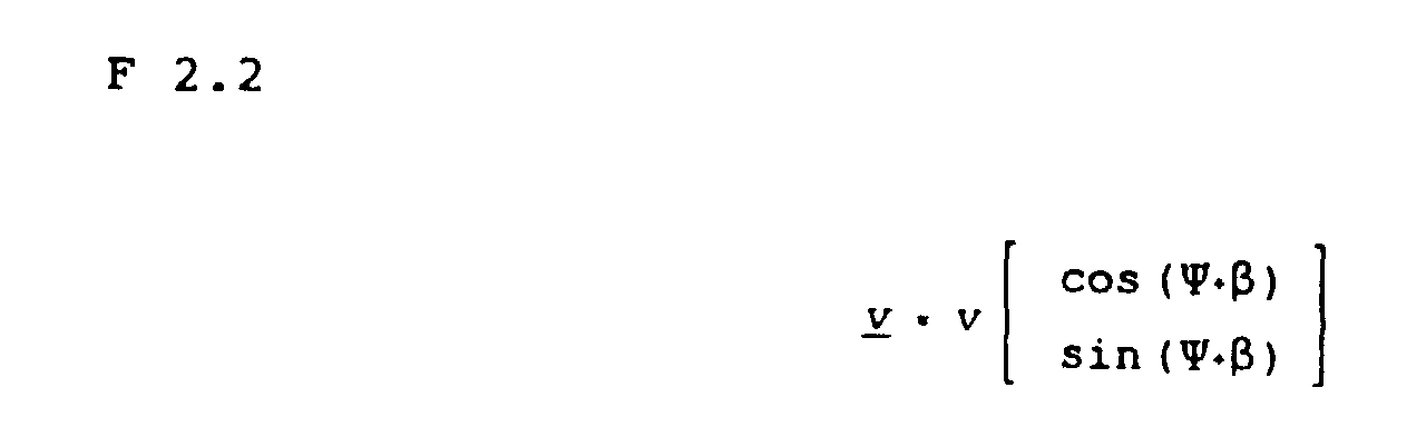


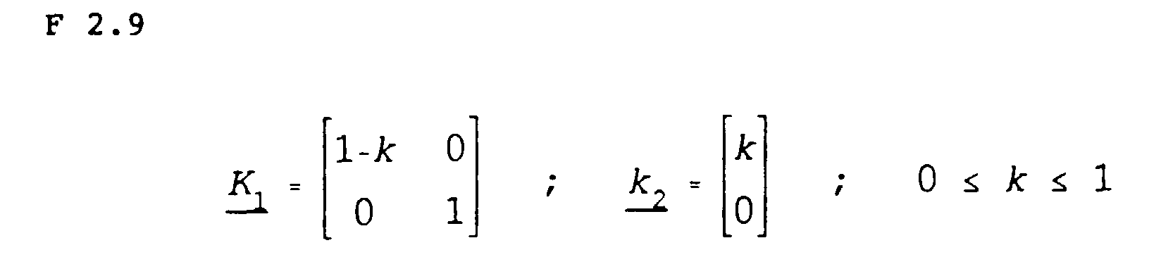
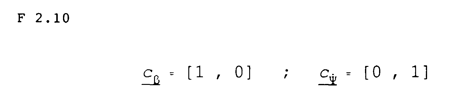

v = vorn; h = hinten; m = Masse; 1 = Abstand der Achse vom Schwerpunkt; Ψ ˙Korr, βkorr = Korrekturglieder für Ψ ˙, β.
- der Lenkwinkel δ
- der Reibwert µ zwischen Reifen und Fahrbahn,
- das Fahrzeugmasse m
- die Achslastverteilung Nz.
- die Fläche A der Bremskolben
- die Anzahl n der Kolben pro Radbremse
- der Reibungskoeffizient µR zwischen Scheibe und Bremsbelag
- das Verhältnis s von effektivem Reibradius zu dynamischem Reifenhalbmesser
- sowie der Wirkungsgrad η der Bremse.
| v | vorne | h | hinten |
| l | links | r | rechts |
| x | steht entweder für v/l oder h/r |
- Ψ ˙Mess =
- gI als gemessener Istwert der Gierwinkelgeschwindigkeit
- =

- g ˙I als gemessener Istwert der Gierwinkelbeschleunigung
- d / dt=

- als gemessener Istwert der Gierwinkelbeschleunigungsgungsänderung (Gierwinkelruck)


Claims (3)
- Vorrichtung zur Regelung des Giermomentes eines vierrädrigen Kraftfahrzeuges während einer Kurvenfahrt, mit einem Fahrzeugreferenzmodell (12), welches die Abweichung (ΔΨ ˙) einer gemessenen Gierwinkelgeschwindigkeit (Ψ ˙mess) von einer berechneten Sollgierwinkelgeschwindigkeit berechnet, und mit einer Aktivierungslogik (11), welche in bestimmten Fahrsituation eine Giermomentregelung veranlaßt, wenn diese Abweichung eine bestimmte Schwelle überschreitet, dadurch gekennzeichnet, daß eine Situationserkennung (13) an die Aktivierungslogik (11) zumindest Informationen darüber gibt, ob sich das Fahrzeug in einer Rückwärtsfahrt befindet, daß Rückwärtsfahrt zumindest immer dann erkannt wird, wenn die gemessene Gierwinkelgeschwindigkeit (Ψ ˙mess) und die Sollgierwinkelgeschwindigkeit (Ψ ˙soll) entgegengesetzte Vorzeichen haben, und dies auch für deren zeitliche Ableitungen (Ψ ˙mess,Ψ ˙soll ) gilt, und daß die Aktivierungslogik (11) bei Rückwärtfahrt keine Giermomentregelung zuläßt.
- Vorrichtung nach Anspruch 1, dadurch gekennzechnet, daß die Situationserkennung (13) die Annahme einer Rückwärtsfahrt solange beibehält, bis die Fahrzeuggeschwindigkeit (vref) so klein ist, daß eine Fahrzeugstillstandssituation angenommen wird.
- Vorrichtung nach Anspruch 1 oder 2, dadurch gekennzeichnet, daß die Situationserkennung (13) nur dann aufgrund einer gemessenen Querbeschleunigung (aquer) eine Kurvenfahrt annimmt, wenn ein Lenkwinkel (δ) gemessen wird, der betragsmäßig eine vorgegebene Minimalschwelle (δmin) überschreitet.
Applications Claiming Priority (11)
| Application Number | Priority Date | Filing Date | Title |
|---|---|---|---|
| DE4441957 | 1994-11-25 | ||
| DE4441956 | 1994-11-25 | ||
| DE4441958 | 1994-11-25 | ||
| DE4441959 | 1994-11-25 | ||
| DE4441956 | 1994-11-25 | ||
| DE4441959 | 1994-11-25 | ||
| DE4441958 | 1994-11-25 | ||
| DE4441957 | 1994-11-25 | ||
| DE4447313 | 1994-12-31 | ||
| DE4447313 | 1994-12-31 | ||
| PCT/EP1995/004656 WO1996016850A1 (de) | 1994-11-25 | 1995-11-25 | System zur fahrstabilitätsregelung |
Publications (2)
| Publication Number | Publication Date |
|---|---|
| EP0794885A1 EP0794885A1 (de) | 1997-09-17 |
| EP0794885B1 true EP0794885B1 (de) | 2000-02-16 |
Family
ID=27511785
Family Applications (6)
| Application Number | Title | Priority Date | Filing Date |
|---|---|---|---|
| EP95940245A Withdrawn EP0792226A1 (de) | 1994-11-25 | 1995-11-25 | Bremsanlage für ein kraftfahrzeug |
| EP95941020A Expired - Lifetime EP0794885B1 (de) | 1994-11-25 | 1995-11-25 | System zur fahrstabilitätsregelung |
| EP95940247A Expired - Lifetime EP0792228B1 (de) | 1994-11-25 | 1995-11-25 | System zur fahrstabilitätsregelung |
| EP95940246A Expired - Lifetime EP0792227B1 (de) | 1994-11-25 | 1995-11-25 | Fahrstabilitätsregler mit reibwertabhängiger begrenzung der referenzgierrate |
| EP95941021A Expired - Lifetime EP0792229B1 (de) | 1994-11-25 | 1995-11-25 | System zur fahrstabilitätsregelung |
| EP95940244A Expired - Lifetime EP0792225B1 (de) | 1994-11-25 | 1995-11-25 | Bremsanlage |
Family Applications Before (1)
| Application Number | Title | Priority Date | Filing Date |
|---|---|---|---|
| EP95940245A Withdrawn EP0792226A1 (de) | 1994-11-25 | 1995-11-25 | Bremsanlage für ein kraftfahrzeug |
Family Applications After (4)
| Application Number | Title | Priority Date | Filing Date |
|---|---|---|---|
| EP95940247A Expired - Lifetime EP0792228B1 (de) | 1994-11-25 | 1995-11-25 | System zur fahrstabilitätsregelung |
| EP95940246A Expired - Lifetime EP0792227B1 (de) | 1994-11-25 | 1995-11-25 | Fahrstabilitätsregler mit reibwertabhängiger begrenzung der referenzgierrate |
| EP95941021A Expired - Lifetime EP0792229B1 (de) | 1994-11-25 | 1995-11-25 | System zur fahrstabilitätsregelung |
| EP95940244A Expired - Lifetime EP0792225B1 (de) | 1994-11-25 | 1995-11-25 | Bremsanlage |
Country Status (11)
| Country | Link |
|---|---|
| US (3) | US5711025A (de) |
| EP (6) | EP0792226A1 (de) |
| JP (4) | JP4091110B2 (de) |
| KR (5) | KR970706155A (de) |
| CN (5) | CN1166813A (de) |
| AU (6) | AU4176096A (de) |
| CZ (5) | CZ158997A3 (de) |
| DE (20) | DE19515055A1 (de) |
| HU (4) | HUT77226A (de) |
| PL (2) | PL320164A1 (de) |
| WO (6) | WO1996016849A1 (de) |
Families Citing this family (268)
| Publication number | Priority date | Publication date | Assignee | Title |
|---|---|---|---|---|
| JP3387692B2 (ja) * | 1995-05-16 | 2003-03-17 | 三菱自動車工業株式会社 | 車両の旋回制御装置 |
| DE19521086A1 (de) * | 1995-06-09 | 1996-12-12 | Teves Gmbh Alfred | Verfahren zum Einregeln eines vorgegebenen, veränderlichen Bremsdruckes in den Radbremsen einer Bremsanlage |
| JP3463415B2 (ja) * | 1995-06-22 | 2003-11-05 | 日産自動車株式会社 | 車両のヨーイング挙動制御装置 |
| TW330182B (en) * | 1995-09-26 | 1998-04-21 | Honda Motor Co Ltd | Process for controlling yaw moment in a vehicle |
| DE19607185A1 (de) * | 1996-02-27 | 1997-08-28 | Bayerische Motoren Werke Ag | Verfahren zur Sicherstellung eines neutralen Fahrverhaltens bei Kurvenfahrten und gleichzeitigem Lastwechsel |
| DE19611491B4 (de) * | 1996-03-23 | 2007-01-04 | Robert Bosch Gmbh | Vorrichtung zur Ansteuerung von Brems-Aktuatoren |
| JPH09301142A (ja) * | 1996-05-10 | 1997-11-25 | Aisin Seiki Co Ltd | 車両の制動力制御装置 |
| DE19623595A1 (de) * | 1996-06-13 | 1997-12-18 | Teves Gmbh Alfred | Verfahren zur Regelung des Fahrverhaltens eines Fahrzeugs |
| DE19624376A1 (de) * | 1996-06-19 | 1998-01-02 | Teves Gmbh Alfred | Bremsanlage für Kraftfahrzeuge |
| DE19632337C2 (de) * | 1996-08-10 | 2000-12-14 | Daimler Chrysler Ag | Verfahren und Einrichtung zur Regelung der Längsdynamik eines Kraftfahrzeuges |
| US5878357A (en) * | 1996-09-03 | 1999-03-02 | Ford Global Technologies, Inc. | Method and apparatus for vehicle yaw rate estimation |
| JPH10119743A (ja) * | 1996-10-23 | 1998-05-12 | Aisin Seiki Co Ltd | 車両の運動制御装置 |
| DE19648909A1 (de) * | 1996-11-26 | 1998-05-28 | Teves Gmbh Alfred | Verfahren und Vorrichtung zur Verbesserung des Regelverhaltens einer blockiergeschützten Bremsanlage |
| JP3946294B2 (ja) * | 1996-11-29 | 2007-07-18 | 富士重工業株式会社 | 制動力制御装置 |
| JP3735995B2 (ja) * | 1997-01-20 | 2006-01-18 | アイシン精機株式会社 | 車両の運動制御装置 |
| DE19704841A1 (de) | 1997-02-08 | 1998-08-13 | Itt Mfg Enterprises Inc | Verfahren und Vorrichtung zur Regelung der Längsdynamik eines Fahrzeugs |
| JP3425728B2 (ja) | 1997-03-28 | 2003-07-14 | 三菱ふそうトラック・バス株式会社 | 車両の挙動制御装置 |
| JP3713893B2 (ja) * | 1997-05-16 | 2005-11-09 | 日産自動車株式会社 | 車両のヨーイング運動量制御装置 |
| JPH1134831A (ja) * | 1997-05-21 | 1999-02-09 | Denso Corp | ブレーキ制御装置 |
| JP3915197B2 (ja) * | 1997-07-10 | 2007-05-16 | トヨタ自動車株式会社 | 車輌のブレーキ装置 |
| DE19752061A1 (de) * | 1997-11-25 | 1999-05-27 | Itt Mfg Enterprises Inc | Verfahren zur Verbesserung des Regelverhaltens eines Kraftfahrzeug-Regelungssystems |
| DE19753907A1 (de) * | 1997-12-05 | 1999-06-10 | Itt Mfg Enterprises Inc | Verbundsystem zur Regelung des Fahrverhaltens eines Kraftfahrzeugs |
| DE19843221B4 (de) * | 1998-01-07 | 2011-11-17 | Continental Teves Ag & Co. Ohg | Fahrdynamikregelsystem und Verfahren zum Betreiben eines solchen Fahrdynamikregelsystems |
| DE19809886A1 (de) | 1998-03-07 | 1999-09-09 | Bosch Gmbh Robert | Elektronisches Gerät mit Bedientasten |
| DE19812237C1 (de) | 1998-03-20 | 1999-09-23 | Daimler Chrysler Ag | Verfahren zur Fahrdynamik-Regelung an einem Straßenfahrzeug |
| DE19817686A1 (de) * | 1998-04-21 | 1999-10-28 | Wabco Gmbh | Verfahren zur Bestimmung einer Vergleichsgröße |
| DE19818860C2 (de) * | 1998-04-28 | 2001-04-19 | Daimler Chrysler Ag | Verfahren und Einrichtung zur Detektion und Lokalisation von Sensorfehlern in Kraftfahrzeugen |
| JP2002514547A (ja) | 1998-05-12 | 2002-05-21 | ダイムラークライスラー・アクチエンゲゼルシヤフト | タイヤスリップ要求値に依存して車両の走行安定性制御方法およびこの方法の実施に適した回路 |
| DE19821617C1 (de) * | 1998-05-15 | 1999-09-30 | Daimler Chrysler Ag | Verfahren und Vorrichtung zur Messung des Neigungswinkels in seitlich geneigten Kurven und deren Verwendung |
| DE19825304A1 (de) * | 1998-06-05 | 1999-12-09 | Bayerische Motoren Werke Ag | Radbremsregelsystem für Kraftfahrzeuge |
| US6370467B1 (en) | 1998-08-10 | 2002-04-09 | Ford Global Technologies, Inc. | Method of calculating optimal wheelslips for brake controller |
| US6292735B1 (en) | 1998-08-10 | 2001-09-18 | Ford Global Technologies, Inc. | Wheelslip regulating brake control |
| DE19849508B4 (de) | 1998-10-27 | 2010-06-17 | Wabco Gmbh | Verfahren zur Regelung des Fahrverhaltens eines Fahrzeuges |
| JP4119020B2 (ja) * | 1998-10-28 | 2008-07-16 | 本田技研工業株式会社 | 車両制御装置 |
| DE19851978A1 (de) * | 1998-11-11 | 2000-05-25 | Daimler Chrysler Ag | Verfahren zur Regelung der Querdynamik eines Fahrzeuges mit Vorderachs-Lenkung |
| JP3649007B2 (ja) * | 1998-11-27 | 2005-05-18 | トヨタ自動車株式会社 | 車両の後退判定方法及び車両制御装置 |
| JP3707276B2 (ja) * | 1998-12-21 | 2005-10-19 | トヨタ自動車株式会社 | 車輌の運動制御装置 |
| WO2000053447A1 (de) * | 1999-03-08 | 2000-09-14 | Continental Teves Ag & Co. Ohg | Antriebsschlupfregelverfahren mit soll- querbeschleunigung und regelschaltung für die durchführung des antriebsschlupfregelverfahrens |
| DE19916267A1 (de) | 1999-04-12 | 2000-10-19 | Continental Teves Ag & Co Ohg | Verfahren und Vorrichtung zum Überwachen oder zum Beeinflussen der Bewegung eines Fahrzeugs auf einem Weg |
| DE10011779A1 (de) * | 1999-09-10 | 2001-06-21 | Continental Teves Ag & Co Ohg | Verfahren zur Regelung eines Giermoments |
| JP3463622B2 (ja) * | 1999-09-14 | 2003-11-05 | トヨタ自動車株式会社 | 車輌の挙動制御装置 |
| JP3872242B2 (ja) * | 1999-09-21 | 2007-01-24 | トヨタ自動車株式会社 | ブレーキ制御装置 |
| JP4042277B2 (ja) * | 1999-11-29 | 2008-02-06 | アイシン精機株式会社 | 車体横すべり角推定装置 |
| DE19960101B4 (de) * | 1999-12-14 | 2016-03-10 | Continental Automotive Gmbh | Verfahren zur vorausschauenden Bestimmung eines Fahrkorridors eines Kraftfahrzeuges für ein automatisches Abstandsregel- und/oder kontrollsystem |
| US6324446B1 (en) | 1999-12-21 | 2001-11-27 | Ford Global Technologies, Inc. | Roll over stability control for an automotive vehicle |
| US6263261B1 (en) | 1999-12-21 | 2001-07-17 | Ford Global Technologies, Inc. | Roll over stability control for an automotive vehicle |
| US6834218B2 (en) | 2001-11-05 | 2004-12-21 | Ford Global Technologies, Llc | Roll over stability control for an automotive vehicle |
| US6332104B1 (en) | 1999-12-21 | 2001-12-18 | Ford Global Technologies, Inc. | Roll over detection for an automotive vehicle |
| JP3391324B2 (ja) | 1999-12-27 | 2003-03-31 | トヨタ自動車株式会社 | ブレーキ液圧制御装置 |
| DE19963747C2 (de) * | 1999-12-30 | 2002-04-04 | Bosch Gmbh Robert | Verfahren und Vorrichtung zur Stabilisierung eines Fahrzeuges oder eines Fahrzeuggespannes bei Untersteuertendenz |
| DE10002685A1 (de) * | 2000-01-22 | 2001-07-26 | Wabco Gmbh & Co Ohg | Verfahren zur Erkennung des fehlerhaften Einbaus von Sensiermiteln in einem Fahrzeug |
| WO2001083277A1 (de) * | 2000-04-28 | 2001-11-08 | Continental Teves Ag & Co. Ohg | Verfahren zur regelung der fahrstabilität eines fahrzeugs |
| DE10103629B4 (de) * | 2000-04-28 | 2016-07-28 | Continental Teves Ag & Co. Ohg | Verfahren zur Regelung der Fahrstabilität eines Fahrzeugs |
| DE10029061C2 (de) * | 2000-06-13 | 2003-12-11 | Breed Automotive Tech | Rückhaltevorrichtung |
| DE10127481A1 (de) * | 2000-06-16 | 2002-01-31 | Continental Teves Ag & Co Ohg | Verfahren zur Ermittlung oder Abschätzung des Reibungskoeffizienten zwischen den Reibbelägen einer Kraftfahrzeugbremse |
| DE10034873B4 (de) * | 2000-07-18 | 2005-10-13 | Pacifica Group Technologies Pty Ltd | Verfahren und Bremsanlage zum Regeln des Bremsvorgangs bei einem Kraftfahrzeug |
| EP1220771B1 (de) | 2000-08-04 | 2007-08-22 | Continental Teves AG & Co. oHG | Fahrzeugstabilisierende einrichtung |
| US6397127B1 (en) | 2000-09-25 | 2002-05-28 | Ford Global Technologies, Inc. | Steering actuated wheel lift identification for an automotive vehicle |
| US7132937B2 (en) | 2000-09-25 | 2006-11-07 | Ford Global Technologies, Llc | Wheel lift identification for an automotive vehicle using passive and active detection |
| US7109856B2 (en) | 2000-09-25 | 2006-09-19 | Ford Global Technologies, Llc | Wheel lifted and grounded identification for an automotive vehicle |
| US7233236B2 (en) | 2000-09-25 | 2007-06-19 | Ford Global Technologies, Llc | Passive wheel lift identification for an automotive vehicle using operating input torque to wheel |
| US6904350B2 (en) | 2000-09-25 | 2005-06-07 | Ford Global Technologies, Llc | System for dynamically determining the wheel grounding and wheel lifting conditions and their applications in roll stability control |
| US6356188B1 (en) | 2000-09-25 | 2002-03-12 | Ford Global Technologies, Inc. | Wheel lift identification for an automotive vehicle |
| DE10050420A1 (de) * | 2000-10-12 | 2003-03-27 | Bayerische Motoren Werke Ag | Fahrdynamik-Regelsystem eines Kraftfahrzeuges |
| DE10061966A1 (de) * | 2000-12-13 | 2002-06-27 | Deutsch Zentr Luft & Raumfahrt | Regelung des dynamischen Verhaltens eines Fahrzeugs um eine definierte Achse |
| DE10062546B4 (de) * | 2000-12-15 | 2012-08-30 | Robert Bosch Gmbh | Bremsanlage für ein Fahrzeug |
| US6799092B2 (en) | 2001-02-21 | 2004-09-28 | Ford Global Technologies, Llc | Rollover stability control for an automotive vehicle using rear wheel steering and brake control |
| JP3623456B2 (ja) | 2001-02-28 | 2005-02-23 | トヨタ自動車株式会社 | 車輌の走行制御装置 |
| JP2003146199A (ja) * | 2001-11-15 | 2003-05-21 | Honda Motor Co Ltd | 車両状態量の推定方法 |
| US6654674B2 (en) | 2001-11-21 | 2003-11-25 | Ford Global Technologies, Llc | Enhanced system for yaw stability control system to include roll stability control function |
| DE10202579C1 (de) | 2002-01-24 | 2003-05-28 | Daimler Chrysler Ag | Verfahren zur Drucksteuerung |
| DE10208815B4 (de) * | 2002-03-01 | 2011-05-19 | Continental Teves Ag & Co. Ohg | Verfahren zum Ermitteln eines maximalen Reibwertes |
| US6556908B1 (en) | 2002-03-04 | 2003-04-29 | Ford Global Technologies, Inc. | Attitude sensing system for an automotive vehicle relative to the road |
| DE10212582B4 (de) | 2002-03-15 | 2013-11-07 | Volkswagen Ag | Verfahren und Vorrichtung zur Regelung der Fahrdynamik |
| DE10215464B9 (de) * | 2002-03-28 | 2013-11-07 | Volkswagen Ag | Verfahren und Vorrichtung zum Schätzen einer Zustandsgröße |
| JP3541840B2 (ja) * | 2002-05-24 | 2004-07-14 | トヨタ自動車株式会社 | ブレーキ液圧制御装置 |
| DE10226227B4 (de) * | 2002-06-13 | 2016-05-12 | Continental Teves Ag & Co. Ohg | Verfahren zur Stabilisierung eines Fahrzeugs und Einrichtung zur Fahrstabilitätsregelung |
| US6672689B1 (en) * | 2002-06-28 | 2004-01-06 | Continental Teves, Inc. | System and method of regulating manual control of a vehicle in a sliding condition |
| US7194351B2 (en) | 2002-08-01 | 2007-03-20 | Ford Global Technologies, Llc | System and method for determining a wheel departure angle for a rollover control system |
| US7085639B2 (en) | 2002-08-01 | 2006-08-01 | Ford Global Technologies, Llc | System and method for characterizing the road bank for vehicle roll stability control |
| US7302331B2 (en) | 2002-08-01 | 2007-11-27 | Ford Global Technologies, Inc. | Wheel lift identification for an automotive vehicle |
| US7003389B2 (en) | 2002-08-01 | 2006-02-21 | Ford Global Technologies, Llc | System and method for characterizing vehicle body to road angle for vehicle roll stability control |
| US6941205B2 (en) | 2002-08-01 | 2005-09-06 | Ford Global Technologies, Llc. | System and method for deteching roll rate sensor fault |
| US7079928B2 (en) | 2002-08-01 | 2006-07-18 | Ford Global Technologies, Llc | System and method for determining a wheel departure angle for a rollover control system with respect to road roll rate and loading misalignment |
| US20040024504A1 (en) | 2002-08-05 | 2004-02-05 | Salib Albert Chenouda | System and method for operating a rollover control system during an elevated condition |
| US6963797B2 (en) | 2002-08-05 | 2005-11-08 | Ford Global Technologies, Llc | System and method for determining an amount of control for operating a rollover control system |
| US6961648B2 (en) | 2002-08-05 | 2005-11-01 | Ford Motor Company | System and method for desensitizing the activation criteria of a rollover control system |
| US7430468B2 (en) | 2002-08-05 | 2008-09-30 | Ford Global Technologies, Llc | System and method for sensitizing the activation criteria of a rollover control system |
| US7085642B2 (en) | 2002-08-05 | 2006-08-01 | Ford Global Technologies, Llc | Method and system for correcting sensor offsets |
| US20040024505A1 (en) | 2002-08-05 | 2004-02-05 | Salib Albert Chenouda | System and method for operating a rollover control system in a transition to a rollover condition |
| DE10236734A1 (de) * | 2002-08-09 | 2004-02-12 | Bayerische Motoren Werke Ag | Verfahren zum Führen eines mehrspurigen Fahrzeugs auf einer Kurvenbahn |
| DE10239254A1 (de) * | 2002-08-22 | 2004-03-04 | Continental Teves Ag & Co. Ohg | Verfahren zur Regelung der Fahrstabilität |
| JP2004090744A (ja) | 2002-08-30 | 2004-03-25 | Hitachi Unisia Automotive Ltd | ブレーキ圧力推定装置 |
| DE50306863D1 (de) * | 2002-09-05 | 2007-05-03 | Continental Teves Ag & Co Ohg | Verfahren zur steuerung und regelung von digital oder analog einstellbaren stossdämpfern |
| US6691013B1 (en) * | 2002-09-06 | 2004-02-10 | Ford Motor Company | Braking and controllability control method and system for a vehicle with regenerative braking |
| DE10247722A1 (de) † | 2002-10-12 | 2004-05-06 | Wabco Gmbh & Co. Ohg | Verfahren zur Steuerung der Bremsanlage eines Fahrzeugzuges |
| US7653471B2 (en) | 2003-02-26 | 2010-01-26 | Ford Global Technologies, Llc | Active driven wheel lift identification for an automotive vehicle |
| US7239949B2 (en) | 2003-02-26 | 2007-07-03 | Ford Global Technologies, Llc | Integrated sensing system |
| US9162656B2 (en) | 2003-02-26 | 2015-10-20 | Ford Global Technologies, Llc | Active driven wheel lift identification for an automotive vehicle |
| US6957875B2 (en) | 2003-03-07 | 2005-10-25 | Advics Co., Ltd. | Vehicle brake squeal control device |
| US6856885B2 (en) * | 2003-04-01 | 2005-02-15 | General Motors Corporation | Vehicle stability enhancement control |
| DE10316413B4 (de) * | 2003-04-10 | 2011-02-03 | Man Nutzfahrzeuge Ag | Verfahren und Vorrichtung zur Spurführung eines Fahrzeugs, insbesondere Nutzfahrzeugs |
| US6885931B2 (en) * | 2003-04-24 | 2005-04-26 | Visteon Global Technologies, Inc. | Control algorithm for a yaw stability management system |
| US7136731B2 (en) | 2003-06-11 | 2006-11-14 | Ford Global Technologies, Llc | System for determining vehicular relative roll angle during a potential rollover event |
| US7137673B2 (en) * | 2003-06-27 | 2006-11-21 | Visteon Global Technologies, Inc. | Vehicle yaw stability system and method |
| WO2005005200A2 (en) * | 2003-06-30 | 2005-01-20 | Kelsey-Hayes Company | Method and apparatus for detecting and correcting trailer induced yaw movements in a towing vehicle |
| US7293842B2 (en) | 2003-07-02 | 2007-11-13 | Haldex Brake Products Ltd. | Control network for vehicle dynamics and ride control systems having distributed electronic control units |
| GB2403708B (en) * | 2003-07-09 | 2005-05-25 | Hsi-Tsai Chen | An expandible reel, spindle or the like for holding a roll of web material. |
| WO2005007489A1 (de) * | 2003-07-11 | 2005-01-27 | Continental Teves Ag & Co. Ohg | Verfahren zum ermitteln eines istwertes einer stellgrösse, insbesondere eines lenkwinkels |
| JP4241248B2 (ja) | 2003-07-17 | 2009-03-18 | 株式会社アドヴィックス | 車両の運動制御装置 |
| US7007763B2 (en) * | 2003-09-19 | 2006-03-07 | Borgwarner Inc. | Control system for interactive driveline and vehicle control |
| DE102004017845B4 (de) * | 2003-09-24 | 2016-02-25 | Continental Teves Ag & Co. Ohg | Verfahren zum Ermitteln des Giermoments |
| DE10348399B4 (de) | 2003-10-17 | 2019-05-23 | Robert Bosch Gmbh | Verfahren und Vorrichtung zum Verbessern der Steuerbarkeit eines Fahrzeugs in einer fahrdynamischen Grenzsituation |
| US7769520B2 (en) * | 2003-10-27 | 2010-08-03 | Ford Global Technologies, Llc | Tractive force map |
| DE10355701A1 (de) * | 2003-11-28 | 2005-06-16 | Zf Friedrichshafen Ag | Verfahren zum Steuern und Regeln der Fahrdynamik eines Fahrzeugs |
| DE10360728A1 (de) * | 2003-12-23 | 2005-07-21 | Daimlerchrysler Ag | Verfahren und Vorrichtung zur Bestimmung eines Fahrzeugzustandes |
| DE112005000348A5 (de) * | 2004-03-01 | 2007-05-24 | Continental Teves Ag & Co. Ohg | Vorrichtung zum Ermitteln einer Kipptendenz |
| US7502675B2 (en) * | 2004-04-01 | 2009-03-10 | Delphi Technologies, Inc. | Feedforward control of motor vehicle roll angle |
| DE102004019281A1 (de) * | 2004-04-21 | 2005-11-17 | Zf Friedrichshafen Ag | Verfahren zur Fahrstabilitätsregelung eines Fahrzeugs |
| US7308350B2 (en) | 2004-05-20 | 2007-12-11 | Ford Global Technologies, Llc | Method and apparatus for determining adaptive brake gain parameters for use in a safety system of an automotive vehicle |
| US7451032B2 (en) | 2004-06-02 | 2008-11-11 | Ford Global Technologies, Llc | System and method for determining desired yaw rate and lateral velocity for use in a vehicle dynamic control system |
| WO2006000578A1 (de) * | 2004-06-25 | 2006-01-05 | Continental Teves Ag & Co. Ohg | Verfahren und einrichtung zum stabilisieren eines fahrzeugs |
| DE102004035004A1 (de) * | 2004-07-20 | 2006-02-16 | Bayerische Motoren Werke Ag | Verfahren zur Erhöhung der Fahrstabilität eines Kraftfahrzeugs |
| US7191047B2 (en) * | 2004-09-27 | 2007-03-13 | Delphi Technologies, Inc. | Motor vehicle control using a dynamic feedforward approach |
| DE102004046890A1 (de) * | 2004-09-28 | 2006-03-30 | Jungheinrich Ag | Verfahren zur Kippvermeidung von hinterradgelenkten Fahrzeugen, insbesondere Flurförderzeugen |
| US7640081B2 (en) | 2004-10-01 | 2009-12-29 | Ford Global Technologies, Llc | Roll stability control using four-wheel drive |
| US7499787B2 (en) * | 2004-10-07 | 2009-03-03 | Ford Global Technologies, Llc | Traction control system and method for a vehicle |
| DE102005049396A1 (de) * | 2004-10-14 | 2006-04-27 | Continental Teves Ag & Co. Ohg | Verfahren und System zum Steuern des Sperrgrades einer elektronisch steuerbaren Differenzialsperre |
| WO2006040343A1 (de) | 2004-10-14 | 2006-04-20 | Continental Teves Ag & Co. Ohg | Verfahren und vorrichtung zum steuern des sperrgrades einer elektronisch steuerbaren differenzialsperre |
| US7668645B2 (en) | 2004-10-15 | 2010-02-23 | Ford Global Technologies | System and method for dynamically determining vehicle loading and vertical loading distance for use in a vehicle dynamic control system |
| US7715965B2 (en) | 2004-10-15 | 2010-05-11 | Ford Global Technologies | System and method for qualitatively determining vehicle loading conditions |
| JP4701673B2 (ja) * | 2004-10-22 | 2011-06-15 | トヨタ自動車株式会社 | ブレーキシステム |
| JP4480543B2 (ja) * | 2004-11-01 | 2010-06-16 | 三菱電機株式会社 | 運転状況判定システム |
| US7660654B2 (en) | 2004-12-13 | 2010-02-09 | Ford Global Technologies, Llc | System for dynamically determining vehicle rear/trunk loading for use in a vehicle control system |
| CN100404333C (zh) * | 2004-12-22 | 2008-07-23 | 日产自动车株式会社 | 用于机动车辆的制动力控制方法及其控制装置 |
| JP4350670B2 (ja) * | 2005-03-15 | 2009-10-21 | 株式会社日立製作所 | 車両制動力制御装置 |
| US7480547B2 (en) | 2005-04-14 | 2009-01-20 | Ford Global Technologies, Llc | Attitude sensing system for an automotive vehicle relative to the road |
| JP2006298192A (ja) * | 2005-04-21 | 2006-11-02 | Toyota Motor Corp | ブレーキ制御装置 |
| DE102005025287A1 (de) * | 2005-06-02 | 2006-12-07 | Continental Teves Ag & Co. Ohg | Fahrzustandsangepaßte, auf Lenkeingriffen basierende Fahrdynamikregelung |
| US7668637B2 (en) * | 2005-07-22 | 2010-02-23 | O'dea Kevin Austin | Technique for determining motor vehicle slip angle while accounting for road banks |
| US7966113B2 (en) * | 2005-08-25 | 2011-06-21 | Robert Bosch Gmbh | Vehicle stability control system |
| DE102005041745A1 (de) * | 2005-09-02 | 2007-03-08 | Bayerische Motoren Werke Ag | Fahrdynamik-Regelsystem für ein Kraftfahrzeug mit einem System zur beliebigen Veränderung der Antriebsmomentverteilung zwischen den beiden angetriebenen Rädern einer Achse |
| US7590481B2 (en) | 2005-09-19 | 2009-09-15 | Ford Global Technologies, Llc | Integrated vehicle control system using dynamically determined vehicle conditions |
| DE102005046672A1 (de) * | 2005-09-29 | 2007-04-05 | Robert Bosch Gmbh | Nachtsichteinrichtung |
| CN1299938C (zh) * | 2005-11-03 | 2007-02-14 | 重庆邮电学院 | 汽车abs仿人智能控制方法 |
| DE102006051908B4 (de) * | 2005-11-04 | 2020-09-24 | Continental Teves Ag & Co. Ohg | Verfahren zum Regeln der Bremskräfte |
| DE102005053116A1 (de) * | 2005-11-08 | 2007-05-10 | Robert Bosch Gmbh | Fahrdynamikregelungssystem mit Lastwechsel-Funktion |
| US8121758B2 (en) | 2005-11-09 | 2012-02-21 | Ford Global Technologies | System for determining torque and tire forces using integrated sensing system |
| US7600826B2 (en) | 2005-11-09 | 2009-10-13 | Ford Global Technologies, Llc | System for dynamically determining axle loadings of a moving vehicle using integrated sensing system and its application in vehicle dynamics controls |
| DE102005053864A1 (de) | 2005-11-11 | 2007-05-16 | Bosch Gmbh Robert | Fahrdynamikregelungssystem mit erweiterter Bremsfunktion |
| DE102006054425A1 (de) | 2005-11-22 | 2007-05-31 | Continental Teves Ag & Co. Ohg | Verfahren und Vorrichtung zum Ermitteln eines Modellparameters eines Referenzfahrzeugmodells |
| DE102006050215B4 (de) | 2005-11-22 | 2019-05-09 | Continental Teves Ag & Co. Ohg | Verfahren und Vorrichtung zum Stabilisieren eines Kraftfahrzeugs |
| JP5011866B2 (ja) * | 2006-01-23 | 2012-08-29 | 日産自動車株式会社 | 横すべり角推定装置、自動車、及び横すべり角推定方法 |
| DE102007008486B4 (de) * | 2006-02-20 | 2022-10-06 | Continental Teves Ag & Co. Ohg | Verfahren zur Regelung der Fahrstabilität |
| JP4640224B2 (ja) * | 2006-03-15 | 2011-03-02 | 日産自動車株式会社 | 車両走行路の湾曲傾向検出装置およびこれを用いた車両の動作応答制御装置 |
| CN101088818B (zh) * | 2006-06-14 | 2012-03-28 | 比亚迪股份有限公司 | 电动汽车防滑控制系统及方法 |
| CN101088819B (zh) * | 2006-06-14 | 2012-03-28 | 比亚迪股份有限公司 | 混合动力汽车防滑控制系统及方法 |
| DE102006030590B4 (de) * | 2006-07-03 | 2023-11-30 | Continental Automotive Technologies GmbH | Verfahren und Vorrichtung zur Bestimmung der Fahrtrichtung eines Fahrzeugs |
| US8740317B2 (en) * | 2006-08-11 | 2014-06-03 | Robert Bosch Gmbh | Closed-loop control for trailer sway mitigation |
| DE102006044424B4 (de) | 2006-09-21 | 2019-05-09 | Robert Bosch Gmbh | Bestimmung der Soll-Giergeschwindigkeit mittels eines erweiterten Einspurmodells |
| DE102006054805B4 (de) * | 2006-11-21 | 2009-11-26 | Continental Automotive Gmbh | Verfahren und Vorrichtung zum Schätzen einer Reibkennzahl |
| DE102007057605A1 (de) | 2006-11-29 | 2008-06-05 | Continental Teves Ag & Co. Ohg | Vorrichtung zur Bestimmung eines Fahrzustandes und Verfahren zum fahrzustandabhängigen Betrieb einer kombinierten Fahrzeugbremsanlage |
| DE102008013988B4 (de) | 2007-03-13 | 2022-07-21 | Continental Autonomous Mobility Germany GmbH | Verfahren und Vorrichtung zum Durchführen eines Ausweichmanövers |
| DE102007019698B4 (de) * | 2007-04-26 | 2019-05-09 | Ford Global Technologies, Llc | Verfahren und Vorrichtung zum elektrisch gesteuerten Unterstützen einer Fahrbewegung eines Fahrzeugs sowie Fahrzeug |
| DE102008032763A1 (de) | 2007-07-12 | 2009-02-05 | Magna Steyr Fahrzeugtechnik Ag & Co. Kg | Vorrichtung und Verfahren zur Regelung der Fahrdynamik |
| DE102008032754A1 (de) | 2007-07-12 | 2009-07-16 | Magna Steyr Fahrzeugtechnik Ag & Co. Kg | Vorrichtung und Verfahren zur Fahrdynamikreglung eines Fahrzeuges |
| DE102008038642A1 (de) | 2007-08-16 | 2009-02-19 | Continental Teves Ag & Co. Ohg | System und Verfahren zum Stabilisieren eines Kraftfahrzeugs |
| US7917274B2 (en) * | 2007-10-19 | 2011-03-29 | Advics Co., Ltd. | Method and apparatus for vehicle sway detection and reduction |
| DE102008052536A1 (de) | 2007-10-23 | 2009-04-30 | Continental Teves Ag & Co. Ohg | Bremsbereitschaftsfunktion für eine Fahrzeugbremse |
| JP4886655B2 (ja) * | 2007-10-30 | 2012-02-29 | 本田技研工業株式会社 | 車両挙動制御装置 |
| FR2925005A3 (fr) * | 2007-12-14 | 2009-06-19 | Renault Sas | Procede d'estimation de l'adherence d'un vehicule automobile et dispositif correspondant |
| WO2009103665A1 (de) | 2008-02-22 | 2009-08-27 | Continental Teves Ag & Co. Ohg | Verfahren und vorrichtung zum stabilisieren eines fahrzeugs |
| US8527124B2 (en) * | 2008-04-14 | 2013-09-03 | Deere & Company | Traction control method and apparatus for a vehicle with independent drives |
| DE102008021241B4 (de) * | 2008-04-28 | 2018-04-19 | Bombardier Transportation Gmbh | Messwert-Anzeige, insbesondere im Führerstand eines Schienenfahrzeugs |
| DE102008021530A1 (de) * | 2008-04-30 | 2009-11-12 | Ford Global Technologies, LLC, Dearborn | Vorrichtung und Verfahren zur Fahrzeugsteuerung |
| DE102008046259B4 (de) * | 2008-09-08 | 2019-10-31 | Volkswagen Ag | Verfahren und Vorrichtung zum Bestimmen einer Fahrstabilität eines Fahrzeugs beim Bremsen und Verfahren und Vorrichtung zum Einstellen eines Bremsdrucks für ein Fahrzeug |
| FR2939748A3 (fr) * | 2008-12-17 | 2010-06-18 | Renault Sas | Procede de commande d'un vehicule automobile en situation de virage. |
| WO2010113799A1 (ja) * | 2009-03-30 | 2010-10-07 | 本田技研工業株式会社 | 車両横滑り運動状態量推定装置 |
| US8067829B2 (en) * | 2009-04-29 | 2011-11-29 | Bae Systems Information And Electronic Systems Integration Inc. | System and method for multi-chip module die extraction and replacement |
| DE102010028384A1 (de) | 2009-05-07 | 2010-11-11 | Continental Teves Ag & Co. Ohg | Verfahren und Vorrichtung zur Regelung bzw. Steuerung der Fahrstabilität eines Fahrzeugs |
| US8838353B2 (en) * | 2009-07-24 | 2014-09-16 | Robert Bosch Gmbh | Trailer sway mitigation using measured distance between a trailer and a tow vehicle |
| US8326504B2 (en) * | 2009-07-30 | 2012-12-04 | Robert Bosch Gmbh | Holistic control for stabilizing vehicle-trailer swaying |
| US7944070B2 (en) * | 2009-08-25 | 2011-05-17 | Vestas Wind Systems A/S | Yaw system for a nacelle of a wind turbine and wind turbine |
| DE102009041566B4 (de) | 2009-09-15 | 2022-01-20 | Continental Teves Ag & Co. Ohg | Verfahren zur Klassifizierung des Fahrbahnreibwerts |
| DE102009046337A1 (de) * | 2009-11-03 | 2011-05-05 | Robert Bosch Gmbh | Verfahren zur Einstellung eines Grenzwerts einer Fahrzeugzustandsgröße bei einem Unfall |
| DE102010004113B4 (de) * | 2010-01-07 | 2014-11-20 | Continental Automotive Gmbh | Verfahren und Vorrichtung zur Ermittlung eines maximalen Reibungsbeiwerts μmax zwischen einem Reifen und einem Untergrund |
| CN101786452B (zh) * | 2010-03-25 | 2013-01-30 | 清华大学 | 轴驱电动车辆驱动防滑控制系统 |
| DE102011077153B4 (de) | 2010-06-09 | 2022-08-04 | Continental Teves Ag & Co. Ohg | Verfahren zum Modifizieren einer Fahrstabilitätsregelung eines Fahrzeugs und Elektronisches Steuergerät |
| DE102010033530A1 (de) * | 2010-06-24 | 2011-12-29 | Continental Teves Ag & Co. Ohg | Verfahren und System zur Fahrspurenmittenführung eines Kraftfahrzeugs |
| DE102011076633A1 (de) * | 2010-09-14 | 2012-03-15 | Robert Bosch Gmbh | Schräglagenabhängige Anpassung einer Bremskraftregelung bei einspurigen Fahrzeugen |
| JP5510255B2 (ja) * | 2010-10-01 | 2014-06-04 | トヨタ自動車株式会社 | 車両の操作状態判定システム |
| DE102011084534A1 (de) | 2010-10-18 | 2012-04-19 | Continental Teves Ag & Co. Ohg | Fehlersichere Parkbremse für Kraftfahrzeuge |
| US9061663B2 (en) | 2010-10-27 | 2015-06-23 | Robert Bosch Gmbh | Trailer sway mitigation using torque vectoring |
| US8311693B2 (en) * | 2010-11-19 | 2012-11-13 | Robert Bosch Gmbh | Energy management for hybrid electric vehicle during trailer sway |
| CN102485528B (zh) * | 2010-12-03 | 2014-08-13 | 比亚迪股份有限公司 | 轮边电机打滑处理控制系统及轮边电机的打滑处理方法 |
| DE102012203182A1 (de) | 2011-03-01 | 2012-09-06 | Continental Teves Ag & Co. Ohg | Sicherheitsvorrichtung für ein Kraftfahrzeug und Verfahren zum Betrieb eines Kraftfahrzeugs |
| EP2681085B1 (de) | 2011-03-01 | 2017-05-10 | Continental Teves AG & Co. oHG | Verfahren und vorrichtung zur prädiktion und adaption von bewegungstrajektorien von kraftfahrzeugen |
| WO2012120076A1 (de) | 2011-03-09 | 2012-09-13 | Continental Teves Ag & Co. Ohg | Sicherheitsvorrichtung für ein kraftfahrzeug und verfahren zum betrieb eines kraftfahrzeugs |
| CN102267460B (zh) * | 2011-05-26 | 2013-07-24 | 上海理工大学 | 一种基于轮胎垂向载荷分配的车辆稳定性控制方法 |
| WO2013011058A1 (de) | 2011-07-19 | 2013-01-24 | Continental Teves Ag & Co. Ohg | Verfahren zur verbesserung der fahrstabilität |
| DE102012214337A1 (de) | 2011-08-11 | 2013-03-14 | Continental Teves Ag & Co. Ohg | Verfahren zur Erkennung eines Fahrzeugstillstands |
| CN103857571B (zh) | 2011-09-28 | 2017-11-21 | 大陆-特韦斯贸易合伙股份公司及两合公司 | 用于电驱动机动车的防滑调节的制动系统 |
| KR101415208B1 (ko) | 2011-10-14 | 2014-08-07 | 주식회사 만도 | 차량 제어 장치 및 방법 |
| US9550480B2 (en) | 2011-10-21 | 2017-01-24 | Autoliv Nissin Brake Systems Japan Co., Ltd. | Vehicle brake hydraulic pressure control apparatus and road surface friction coefficient estimating device |
| DE102011121454A1 (de) | 2011-12-16 | 2013-06-20 | Audi Ag | Steuervorrichtung für einen Kraftwagen, Kraftwagen sowie Verfahren zum Konfigurieren der Steuervorrichtung |
| DE102012222490B4 (de) | 2011-12-20 | 2023-06-22 | Continental Automotive Technologies GmbH | Verfahren zur Erhöhung der Fahrstabilität eines Fahrzeugs |
| DE102011121822A1 (de) | 2011-12-21 | 2013-06-27 | Wabco Gmbh | Verfahren und Einrichtung zum Bestimmen der Einbaulage eines Sensormoduls in einem Fahrzeug sowie Fahrzeug mit einer derartigen Einrichtung |
| DE102012202467A1 (de) | 2012-02-17 | 2013-08-22 | Continental Teves Ag & Co. Ohg | Verfahren zur Ansteuerung eines Bremssystems, Bremssystem und Verwendung |
| WO2013191765A1 (en) * | 2012-06-21 | 2013-12-27 | Eaton Corporation | Predictive vehicle stability control method |
| DE102012222489A1 (de) | 2012-12-06 | 2014-06-12 | Continental Teves Ag & Co. Ohg | Verfahren zur Regelung der Fahrdynamik |
| DE102012222549B4 (de) | 2012-12-07 | 2023-01-12 | Continental Automotive Technologies GmbH | Verfahren zur Überwachung eines Lenkwinkelsensors |
| DE102012222993A1 (de) | 2012-12-12 | 2014-06-12 | Continental Teves Ag & Co. Ohg | Verfahren zum Stabilisieren eines Gespanns |
| DE102012223296A1 (de) | 2012-12-14 | 2014-06-18 | Continental Teves Ag & Co. Ohg | Verfahren zum Betreiben eines Bremssystems |
| DE112013006126A5 (de) | 2012-12-20 | 2015-09-10 | Continental Teves Ag & Co. Ohg | Verfahren und Vorrichtung zum automatisierten Bremsen und Lenken eines Fahrzeugs |
| DE102012112725A1 (de) | 2012-12-20 | 2014-06-26 | Continental Teves Ag & Co. Ohg | Reibwertschätzung aus Kamera- und Raddrehzahldaten |
| DE102012112724A1 (de) | 2012-12-20 | 2014-06-26 | Continental Teves Ag & Co. Ohg | Verfahren zur Bestimmung eines Fahrbahnzustands aus Umfeldsensordaten |
| US8918263B2 (en) | 2013-03-14 | 2014-12-23 | Clark Equipment Company | Traction control for power machine |
| DE102013220582A1 (de) | 2013-10-11 | 2015-04-16 | Continental Teves Ag & Co. Ohg | Verfahren zum Betreiben eines Bremssystems |
| DE102013113872B4 (de) | 2013-12-11 | 2018-04-05 | Audi Ag | Vorrichtungen und Verfahren zum Ausgleichen einer fahrtrichtungsabhängigen Längsgeschwindigkeitsbeeinflussung |
| DE102014203752A1 (de) | 2014-02-28 | 2015-09-17 | Continental Teves Ag & Co. Ohg | Verfahren zur Regelung der Querdynamik eines Kraftfahrzeugs |
| DE102014208625A1 (de) | 2014-05-08 | 2015-11-12 | Continental Teves Ag & Co. Ohg | Verfahren zur Regelung der Fahrdynamik eines Kraftfahrzeugs |
| DE102014209526A1 (de) | 2014-05-20 | 2015-11-26 | Continental Teves Ag & Co. Ohg | Regelschaltung zum Regeln der Fahrstabilität eines Fahrzeuges und Verfahren zur Bereitstellung einer solchen Regelschaltung |
| US10408323B2 (en) | 2014-07-16 | 2019-09-10 | Dana Automotive Systems Group, Llc | Drive unit with twin side shaft torque coupling |
| CN105691403B (zh) * | 2014-11-27 | 2018-08-24 | 沈阳工业大学 | 四轮全驱电动汽车路面附着系数估计方法 |
| CN105151047B (zh) * | 2015-09-08 | 2018-08-24 | 吉林大学 | 一种汽车质心侧偏角测量方法 |
| TW201710924A (zh) * | 2015-09-14 | 2017-03-16 | 義守大學 | 以多項式估測感應機參數之方法 |
| US10108197B2 (en) * | 2015-12-08 | 2018-10-23 | Ford Global Technologies, Llc | Deceleration determination of a vehicle |
| JP6578212B2 (ja) | 2016-01-08 | 2019-09-18 | Ntn株式会社 | 車両の旋回制御装置 |
| DE102016206077A1 (de) * | 2016-04-12 | 2017-10-12 | Robert Bosch Gmbh | Verfahren und Vorrichtung zum Bestimmen einer sicherheitskritischen Gierbewegung eines Fahrzeugs |
| DE102016210921A1 (de) * | 2016-06-20 | 2018-01-04 | Robert Bosch Gmbh | Verfahren zur Durchführung eines fahrerunabhängigen Bremsvorgangs eines Kraftfahrzeugs |
| JP6638619B2 (ja) * | 2016-10-25 | 2020-01-29 | トヨタ自動車株式会社 | 車線逸脱抑制装置 |
| KR101868843B1 (ko) * | 2016-11-29 | 2018-06-19 | 주식회사 만도 | 차량 제어 장치 및 그 제어 방법 |
| CN106696755B (zh) * | 2016-12-19 | 2019-04-26 | 北京理工大学 | 一种车辆转矩分配装置及方法 |
| US10197144B2 (en) | 2017-01-20 | 2019-02-05 | Dana Heavy Vehicle Systems Group, Llc | Drive unit with torque vectoring and an axle disconnect and reconnect mechanism |
| US20180319381A1 (en) * | 2017-05-05 | 2018-11-08 | Caterpillar Inc. | Control system and method for anti-lock braking system for autonomous vehicle |
| US10300897B2 (en) * | 2017-05-15 | 2019-05-28 | Goodrich Corporation | Brake load balance and runway centering techniques |
| DE102017214070A1 (de) * | 2017-08-11 | 2019-02-14 | Robert Bosch Gmbh | Verfahren und Vorrichtung zum Ermitteln eines Reibwertes einer Fahrbahn |
| US10821981B1 (en) * | 2017-10-18 | 2020-11-03 | Zoox, Inc. | Independent control of vehicle wheels |
| US11136021B1 (en) | 2017-10-18 | 2021-10-05 | Zoox, Inc. | Independent control of vehicle wheels |
| US10488172B1 (en) | 2017-10-18 | 2019-11-26 | Zoox, Inc. | Independent control of vehicle wheels |
| US10759416B1 (en) | 2017-10-18 | 2020-09-01 | Zoox, Inc. | Independent control of vehicle wheels |
| KR102432432B1 (ko) * | 2017-12-05 | 2022-08-17 | 현대자동차주식회사 | 차량 및 그 제어방법 |
| JP6554568B2 (ja) * | 2018-01-24 | 2019-07-31 | 本田技研工業株式会社 | 車両制御装置 |
| DE102018201190A1 (de) | 2018-01-25 | 2019-07-25 | Audi Ag | Verfahren zum Betrieb eines Fahrerassistenzsystems |
| CN109733461B (zh) * | 2018-02-13 | 2023-04-14 | 重庆长安汽车股份有限公司 | 自动驾驶车辆的冗余电子转向系统及控制方法 |
| JP7194376B2 (ja) * | 2018-02-19 | 2022-12-22 | マツダ株式会社 | 車両の制御装置 |
| CN110386134B (zh) * | 2018-04-12 | 2024-02-06 | 罗伯特·博世有限公司 | 车辆稳定性控制模块和控制方法 |
| CN109094543A (zh) * | 2018-06-20 | 2018-12-28 | 苏州工业园区职业技术学院 | 一种车身稳定系统 |
| DE102018116512A1 (de) * | 2018-07-09 | 2020-01-09 | Valeo Schalter Und Sensoren Gmbh | Neue odometrische Berechnungen für eine Eigenbewegung eines Kraftfahrzeugs auf Basis einer Abschätzung von Steifigkeitskoeffizienten |
| CN108995637B (zh) * | 2018-07-25 | 2020-08-04 | 合肥市智信汽车科技有限公司 | 一种车辆制动控制装置以及控制方法 |
| JP7032275B2 (ja) * | 2018-09-21 | 2022-03-08 | トヨタ自動車株式会社 | 車両用制動制御装置 |
| CN111098849B (zh) * | 2018-10-29 | 2021-04-27 | 香港城市大学深圳研究院 | 一种新能源汽车稳定性控制方法及系统 |
| DE102018132157B3 (de) | 2018-12-13 | 2020-06-18 | Nira Dynamics Ab | Reifensteifigkeitsschätzung und Fahrbahnreibungsschätzung |
| DE102019101390A1 (de) * | 2019-01-21 | 2020-07-23 | Dr. Ing. H.C. F. Porsche Aktiengesellschaft | Verfahren zum Betrieb einer Fahrzeugbremseinrichtung, System und Computerprogramm |
| EP3696053B1 (de) * | 2019-02-15 | 2021-08-25 | Volkswagen Ag | Steer-by-wire-lenksystem für ein fahrzeug und verfahren zum betreiben eines steer-by-wire-lenksystems |
| JP7189060B2 (ja) * | 2019-03-27 | 2022-12-13 | トヨタ自動車株式会社 | 車両走行制御システム |
| CN111762172A (zh) * | 2019-04-01 | 2020-10-13 | 江西理工大学 | 一种基于电-液参数的路面附着估计方法 |
| CN110550035B (zh) * | 2019-08-14 | 2022-03-18 | 平安科技(深圳)有限公司 | 驾驶行为检测方法、装置、计算机设备及存储介质 |
| DE102019219263A1 (de) * | 2019-12-10 | 2021-06-10 | Continental Teves Ag & Co. Ohg | Verfahren und System zur Verbesserung der Fahrstabilität |
| CN111306009B (zh) * | 2020-03-18 | 2022-03-08 | 西安热工研究院有限公司 | 一种风机偏航系统制动盘磨损量在线测量方法 |
| DE102020209169A1 (de) | 2020-07-21 | 2022-01-27 | Continental Automotive Gmbh | Verfahren zur Unterstützung des Fahrzeugführers eines Ego-Fahrzeugs beim Durchfahren einer vorausliegenden Kurve |
| AT523916B1 (de) * | 2020-07-24 | 2022-01-15 | Avl List Gmbh | Verfahren und System zum Analysieren eines fahrdynamischen Fahrverhaltens eines Fahrzeugs |
| US11648900B2 (en) * | 2020-07-27 | 2023-05-16 | Robert Bosch Gmbh | Off-zone crash detection using lateral accelerations at different positions in a vehicle |
| CN112918482B (zh) * | 2021-03-25 | 2022-12-27 | 东风汽车集团股份有限公司 | 车辆跑偏程度的检测分析方法、系统及存储介质 |
| DE102021211740A1 (de) * | 2021-10-18 | 2023-04-20 | Robert Bosch Gesellschaft mit beschränkter Haftung | Verfahren zum automatisierten Anpassen einer Antischlupfregelung eines Fahrzeugs |
| CN115179977B (zh) * | 2022-07-08 | 2023-10-13 | 广州地铁集团有限公司 | 一种大坡度道岔区列车动力性能调控方法 |
| DE102022125561A1 (de) | 2022-10-04 | 2024-04-04 | Bayerische Motoren Werke Aktiengesellschaft | Verfahren zum Betreiben eines Fahrzeugs und Fahrzeug |
| CN117087628B (zh) * | 2023-10-18 | 2023-12-22 | 江苏智能无人装备产业创新中心有限公司 | 双侧独立电驱动无人驾驶履带车辆制动防跑偏控制方法 |
Family Cites Families (295)
| Publication number | Priority date | Publication date | Assignee | Title |
|---|---|---|---|---|
| DE1902944U (de) | 1964-08-13 | 1964-10-22 | Tipp & Co Fabrik Mechanischer | Modellspielzeug. |
| JPS4820348B1 (de) * | 1968-10-30 | 1973-06-20 | ||
| DE1902944C3 (de) * | 1969-01-22 | 1978-10-12 | Dr.Ing.H.C. F. Porsche Ag, 7000 Stuttgart | Steuereinrichtung zum Vermeiden von Kurvenschleudern bei Kraftfahrzeugen |
| DE2726465A1 (de) | 1977-06-11 | 1978-12-21 | Bosch Gmbh Robert | Zentralsteuerung fuer fahrzeuge |
| DE2752908A1 (de) | 1977-11-26 | 1979-05-31 | Porsche Ag | Kraftfahrzeug mit luftbereiften raedern |
| DE2900461A1 (de) | 1979-01-08 | 1980-07-24 | Bosch Gmbh Robert | Einrichtung zur regelung der fahrgeschwindigkeit eines fahrzeugs |
| US4295540A (en) * | 1979-09-14 | 1981-10-20 | Towmotor Corporation | Vehicle brake and engine interlock |
| DE3033653A1 (de) | 1980-09-06 | 1982-10-07 | Volkswagenwerk Ag, 3180 Wolfsburg | Fuehrungsteil fuer einen sicherheitsgurt |
| DE3127302C2 (de) | 1981-07-10 | 1983-09-15 | Daimler-Benz Ag, 7000 Stuttgart | "Einrichtung zur Vortriebsregelung an Kraftfahrzeugen" |
| DE3127605C2 (de) | 1981-07-13 | 1985-10-17 | Dr.Ing.H.C. F. Porsche Ag, 7000 Stuttgart | Einrichtung zum Zu- und Abschalten eines Vorderradantriebs bei einem allradgetriebenen Kraftfahrzeug |
| JPS58104339A (ja) | 1981-12-15 | 1983-06-21 | Nissan Motor Co Ltd | 車両のエンジンアイドリング安定化装置 |
| US4542460A (en) * | 1982-02-16 | 1985-09-17 | Weber Harold J | Driving aid indicator for economical operation of automatic transmission equipped motor vehicle |
| US4573705A (en) | 1982-11-22 | 1986-03-04 | Mazda Motor Corporation | Suspension and steering control of motor vehicles |
| DE3343007A1 (de) | 1982-11-30 | 1984-05-30 | Toyo Kogyo Co. Ltd., Hiroshima | Anordnung zum verstellen der aufhaengungen und der lenkeinrichtung eines kraftfahrzeuges |
| DE3309712A1 (de) | 1983-03-18 | 1984-09-20 | Bosch Gmbh Robert | Fahrzeug-antriebs-kupplung |
| DE3421776C2 (de) | 1983-06-14 | 1993-09-30 | Bosch Gmbh Robert | Fahrzeug mit Allradantrieb |
| JPS6022547A (ja) | 1983-07-14 | 1985-02-05 | Nissan Motor Co Ltd | ブレ−キ装置 |
| JPS6085068A (ja) | 1983-10-17 | 1985-05-14 | Honda Motor Co Ltd | 車両の前後輪操舵装置 |
| JPS60101356A (ja) | 1983-11-09 | 1985-06-05 | Nissan Motor Co Ltd | 車両用自動変速機のロツクアツプ制御装置 |
| GB2152166A (en) | 1983-12-06 | 1985-07-31 | Ae Plc | Automatic vehicle speed control |
| JPS60161256A (ja) * | 1984-01-31 | 1985-08-22 | Nissan Motor Co Ltd | 車両の補助操舵方法 |
| DE3416292A1 (de) | 1984-05-03 | 1985-11-07 | Bosch Gmbh Robert | Regelschaltung fuer die angetriebenen raeder eines fahrzeugs |
| JPH0613287B2 (ja) * | 1984-05-21 | 1994-02-23 | 日産自動車株式会社 | 車両用制動力制御装置 |
| IT1178969B (it) | 1984-06-15 | 1987-09-16 | Fiat Auto Spa | Apparato di rivviamento automatico del motore di un autoveicolo dopo una frenata brusca in condizione discarsa aderenza |
| JPH064390B2 (ja) | 1984-08-08 | 1994-01-19 | 株式会社曙ブレ−キ中央技術研究所 | 車両の発進制御方法 |
| US4669750A (en) | 1984-08-21 | 1987-06-02 | Mitsubishi Jidosha Kogyo Kabushiki Kaisha | Vehicle suspension apparatus |
| US4679809A (en) * | 1984-09-10 | 1987-07-14 | Nissan Motor Co., Ltd. | Steering control system for wheeled vehicle |
| JPS61108040A (ja) | 1984-10-30 | 1986-05-26 | Toyota Motor Corp | 車輪スリツプ制御装置 |
| SE445629B (sv) | 1984-11-23 | 1986-07-07 | Volvo Ab | Hjelpanordning vid fordonsstart i backe |
| DE3505600A1 (de) | 1985-02-18 | 1986-08-21 | Happel GmbH & Co, 4690 Herne | Verfahren und vorrichtung zur regelung der temperatur in zu temperierenden raeumen |
| JPH06104455B2 (ja) * | 1985-03-15 | 1994-12-21 | 日産自動車株式会社 | 車両運動状態推定装置 |
| JPH0645338B2 (ja) * | 1985-04-09 | 1994-06-15 | 日産自動車株式会社 | アンチスキッド制御装置 |
| DE3618691A1 (de) * | 1985-06-04 | 1986-12-04 | Robert Bosch Gmbh, 7000 Stuttgart | Verfahren zur einstellung eines optimierten bremsschlupfs |
| US4770266A (en) | 1985-08-13 | 1988-09-13 | Mazda Motor Corporation | Brake control system for four-wheel drive vehicle |
| DE3534211A1 (de) | 1985-09-25 | 1987-03-26 | Pfister Gmbh | Kraftfahrzeug und verfahren zu dessen betrieb |
| DE3536185A1 (de) | 1985-10-10 | 1987-04-23 | Daimler Benz Ag | Einrichtung zur generierung einer fuer die fahrgeschwindigkeit eines kraftfahrzeuges mit automatisch zu- und abschaltbarem allradantrieb repraesentativen groesse |
| DE3537452C2 (de) | 1985-10-22 | 1996-06-13 | Bosch Gmbh Robert | Antriebsschlupfregelsystem |
| US4765430A (en) * | 1985-10-24 | 1988-08-23 | Volkswagen Ag | Method and arrangement for propulsion regulation of an automobile |
| DE3543145C2 (de) * | 1985-12-06 | 1995-08-03 | Bosch Gmbh Robert | Elektrisches Bremssystem für ein Fahrzeug |
| DE3545652A1 (de) * | 1985-12-21 | 1987-06-25 | Daimler Benz Ag | Einrichtung zur vortriebsregelung an kraftfahrzeugen |
| DE3545715A1 (de) * | 1985-12-21 | 1987-07-02 | Daimler Benz Ag | Einrichtung zur vortriebsregelung an kraftfahrzeugen |
| JPS62157851A (ja) | 1985-12-28 | 1987-07-13 | Toyota Motor Corp | 加速スリツプ制御装置 |
| JPS62161037A (ja) * | 1986-01-09 | 1987-07-17 | Nippon Denso Co Ltd | 車両に搭載される総合診断装置 |
| JPH0629039B2 (ja) * | 1986-01-10 | 1994-04-20 | 日産自動車株式会社 | 車両運動状態量推定装置 |
| DE3768968D1 (de) | 1986-01-30 | 1991-05-08 | Toyota Motor Co Ltd | Steuerungsverfahren fuer das fahrzeugverhalten. |
| DE3605600A1 (de) | 1986-02-21 | 1987-08-27 | Audi Ag | Antiblockierregelsystem fuer kraftfahrzeuge |
| DE3606797C2 (de) * | 1986-03-01 | 2000-11-23 | Bosch Gmbh Robert | Vorrichtung und Verfahren zur Steuerung, insbesondere zur Begrenzung, der Fahrgeschwindigkeit eines Straßenfahrzeuges |
| JPS62253557A (ja) | 1986-03-24 | 1987-11-05 | Aisin Seiki Co Ltd | アンチスキツド制御装置 |
| DE3612170A1 (de) | 1986-04-11 | 1987-10-15 | Daimler Benz Ag | Einrichtung zur vortriebs-regelung fuer ein kraftfahrzeug mit allradantrieb |
| DE3616907A1 (de) | 1986-05-20 | 1987-11-26 | Hans Prof Dr Ing Marko | Einrichtung zur regelung der drehgeschwindigkeit eines kraftfahrzeuges um die hochachse |
| DE3619474A1 (de) * | 1986-06-10 | 1987-12-17 | Hengstler Bauelemente | Relais zur betaetigung eines gurtstraffers an kraftfahrzeug-sicherheitshaltegurten |
| AT394686B (de) | 1986-07-02 | 1992-05-25 | Steyr Daimler Puch Ag | Kraftfahrzeug mit vierradantrieb |
| US4836618A (en) * | 1986-07-04 | 1989-06-06 | Nippondenso Co., Ltd. | Brake control system for controlling a braking force to each wheel of a motor vehicle |
| US4884651A (en) * | 1986-07-24 | 1989-12-05 | Mazda Motor Corporation | Vehicle slip control apparatus |
| US4779696A (en) | 1986-07-24 | 1988-10-25 | Mazda Motor Corporation | Vehicle slip control apparatus |
| DE3784577T2 (de) * | 1986-07-24 | 1993-06-17 | Mazda Motor | Fahrzeug-schleuder-steuervorrichtung. |
| JPH0698903B2 (ja) * | 1986-08-06 | 1994-12-07 | 本田技研工業株式会社 | 車両走行制御装置 |
| DE3627549A1 (de) * | 1986-08-13 | 1988-02-18 | Daimler Benz Ag | Vorrichtung zum selbsttaetigen umschalten von fahrzeugaggregaten eines kraftfahrzeuges |
| DE3634240A1 (de) | 1986-10-08 | 1988-04-21 | Bosch Gmbh Robert | Antriebsschlupfregeleinrichtung |
| DE3634301A1 (de) | 1986-10-08 | 1988-04-21 | Porsche Ag | Kraftfahrzeug |
| JP2630586B2 (ja) | 1986-10-24 | 1997-07-16 | 日本エ−ビ−エス株式会社 | 車両用ブレーキ調整装置 |
| JPS63112254A (ja) | 1986-10-30 | 1988-05-17 | Sumitomo Electric Ind Ltd | 車輪スピン制御装置 |
| JPH0741784B2 (ja) * | 1986-11-28 | 1995-05-10 | 日産自動車株式会社 | サスペンシヨンとステアリングの総合制御装置 |
| JP2504009B2 (ja) * | 1986-12-13 | 1996-06-05 | トヨタ自動車株式会社 | 加速スリップ制御装置 |
| EP0272700B1 (de) | 1986-12-23 | 1991-04-03 | Mazda Motor Corporation | Steuergerät zur Steuerung einer Vorrichtung in einem Fahrzeug |
| JPH0624912B2 (ja) * | 1987-01-26 | 1994-04-06 | 本田技研工業株式会社 | 車両のアンチロツク制御方法 |
| CA1320551C (en) * | 1987-03-09 | 1993-07-20 | Shuji Shiraishi | Yaw motion control device |
| JP2584765B2 (ja) * | 1987-03-31 | 1997-02-26 | 日産自動車株式会社 | 自動変速機の変速制御装置 |
| DE3710870A1 (de) | 1987-04-01 | 1988-10-20 | Bosch Gmbh Robert | Antriebsschlupfregelsystem |
| US4868755A (en) * | 1987-05-18 | 1989-09-19 | Texas Instruments Incorporated | Expert vehicle control system |
| JP2508093B2 (ja) * | 1987-06-01 | 1996-06-19 | 日本電装株式会社 | 車両用スリップ制御装置 |
| JPS644577A (en) | 1987-06-26 | 1989-01-09 | Ford Motor Co | Car controller having wheel-speed difference input |
| DE3826982C2 (de) * | 1987-08-10 | 2000-11-30 | Denso Corp | Hilfslenksystem verbunden mit einem Antiblockiersteuerungssystem zur Verwendung in Kraftfahrzeugen |
| JPH0780407B2 (ja) * | 1987-08-14 | 1995-08-30 | 株式会社日立製作所 | 電動パワ−ステアリング連動式車高制御装置 |
| DE3728572A1 (de) | 1987-08-27 | 1989-03-16 | Daimler Benz Ag | Einrichtung zur vortriebsregelung an kraftfahrzeugen |
| DE3731756A1 (de) | 1987-09-22 | 1989-03-30 | Bosch Gmbh Robert | Verfahren zur regelung der fahrstabilitaet eines fahrzeugs |
| JP2534730B2 (ja) | 1987-09-29 | 1996-09-18 | 日産自動車株式会社 | 4輪操舵・差動制限力総合制御装置 |
| JPH0195922A (ja) | 1987-10-08 | 1989-04-14 | Mazda Motor Corp | 車両のサスペンション制御装置 |
| WO1989004263A1 (en) | 1987-11-06 | 1989-05-18 | Robert Bosch Gmbh | Drive slip regulating system |
| JP2709927B2 (ja) | 1987-11-24 | 1998-02-04 | 富士重工業株式会社 | 自動車用液圧式制動装置の制動液圧制御方法 |
| JP2618250B2 (ja) * | 1987-12-22 | 1997-06-11 | 富士重工業株式会社 | トラクション制御装置 |
| US4882693A (en) * | 1987-12-28 | 1989-11-21 | Ford Motor Company | Automotive system for dynamically determining road adhesion |
| JP2804760B2 (ja) | 1988-01-22 | 1998-09-30 | 雅彦 三成 | 自動車の操縦制御装置 |
| US5224044A (en) * | 1988-02-05 | 1993-06-29 | Nissan Motor Company, Limited | System for controlling driving condition of automotive device associated with vehicle slip control system |
| GB2215796A (en) * | 1988-02-09 | 1989-09-27 | Fuji Heavy Ind Ltd | Antilock brake control method for motor vehicles |
| DE3804587A1 (de) * | 1988-02-13 | 1989-08-24 | Daimler Benz Ag | Zusatzlenkung |
| JP2600756B2 (ja) * | 1988-02-16 | 1997-04-16 | トヨタ自動車株式会社 | 車両の加速スリップ制御装置 |
| US4955448A (en) | 1988-02-29 | 1990-09-11 | Toyota Jidosha Kabushiki Kaisha | Controller for reducing acceleration slippage of a driven wheel |
| JP2685205B2 (ja) * | 1988-03-14 | 1997-12-03 | マツダ株式会社 | 車両の後輪操舵装置 |
| JP2683655B2 (ja) * | 1988-03-28 | 1997-12-03 | マツダ株式会社 | 4輪駆動車のトルク配分装置 |
| US4926333A (en) | 1988-04-20 | 1990-05-15 | Mitsubishi Jidosha Kogyo Kabushiki Kaisha | Traction control apparatus |
| EP0338588B1 (de) * | 1988-04-22 | 1994-03-23 | Honda Giken Kogyo Kabushiki Kaisha | Steuerung für das Moment an den angetriebenen Rädern eines Fahrzeuges |
| DE68909296T2 (de) | 1988-04-27 | 1994-02-24 | Nissan Motor | Pannensicheres Fahrzeugregelsystem. |
| US5255193A (en) | 1988-05-12 | 1993-10-19 | Nissan Motor Company | Traction control system for controlling engine output and brake for maintaining optimum wheel traction with road friction level dependent brake control |
| DE3915840C2 (de) | 1988-05-19 | 1996-12-19 | Volkswagen Ag | Verfahren zur Vermeidung unbeabsichtigter Beschleunigungen |
| DE3817546A1 (de) * | 1988-05-24 | 1989-12-07 | Bosch Gmbh Robert | Verfahren zur erhoehung der beherrschbarkeit eines gebremsten fahrzeuges |
| JPH01297316A (ja) | 1988-05-26 | 1989-11-30 | Mazda Motor Corp | 車両のサスペンション制御装置 |
| DE3819474C1 (de) * | 1988-06-08 | 1989-11-30 | Daimler-Benz Aktiengesellschaft, 7000 Stuttgart, De | |
| DE3919347C3 (de) * | 1988-06-15 | 2002-05-29 | Aisin Seiki | Einrichtung und Verfahren zur Regelung einer Fahrzeugbewegung |
| US4898431A (en) * | 1988-06-15 | 1990-02-06 | Aisin Seiki Kabushiki Kaisha | Brake controlling system |
| JP2509299B2 (ja) * | 1988-06-22 | 1996-06-19 | 日産自動車株式会社 | 四輪駆動車のアンチスキッド制御装置 |
| DE3825639C2 (de) | 1988-07-28 | 1995-10-12 | Sepp Gunther | Einrichtung zum Stabilisieren von Kraftfahrzeugen bei Kurvenfahrt |
| US5001637A (en) * | 1988-08-01 | 1991-03-19 | Honda Giken Kogyo Kabushiki Kaisha | Steering wheel turning angle detector and method for controlling yawing for vehicle |
| JP2603524B2 (ja) | 1988-08-10 | 1997-04-23 | 本田技研工業株式会社 | 車両のエンジン特性切換装置 |
| US5255194A (en) | 1988-08-17 | 1993-10-19 | Robert Bosch Gmbh | System for maintaining a vehicle equipped with ABS in driving direction during lateral skidding |
| JPH0239167U (de) * | 1988-09-09 | 1990-03-15 | ||
| US5313389A (en) | 1988-09-13 | 1994-05-17 | Aisin Seiki Kabushiki Kaisha | Fail-safe mechanism for vehicle stability augmentation steering system |
| DE3831105C1 (de) | 1988-09-13 | 1990-03-22 | Daimler-Benz Aktiengesellschaft, 7000 Stuttgart, De | |
| JP2724173B2 (ja) | 1988-09-19 | 1998-03-09 | マツダ株式会社 | 4輪駆動車のスリップ制御装置 |
| DE3833588A1 (de) * | 1988-10-03 | 1990-04-05 | Daimler Benz Ag | Antriebsschlupfregeleinrichtung fuer kraftfahrzeuge |
| JPH0299439A (ja) * | 1988-10-05 | 1990-04-11 | Hitachi Ltd | 自動車のキヤラクタライジング装置及びその登録方法 |
| IT1223919B (it) | 1988-11-18 | 1990-09-29 | Leonardo Fioravanti | Procedimento e sistema per la rilevazione delle impronte di appoggio dei pneumatici di un autoveicolo particolarmente per l'ottimizzazione automatica del comportamento del l'autoveicolo |
| JP2627439B2 (ja) * | 1988-11-24 | 1997-07-09 | 本田技研工業株式会社 | 車両の駆動輪スリップ制御装置 |
| DE3840456A1 (de) * | 1988-12-01 | 1990-06-07 | Bosch Gmbh Robert | Verfahren zur erhoehung der beherrschbarkeit eines fahrzeugs |
| DE3840564A1 (de) * | 1988-12-01 | 1990-03-08 | Daimler Benz Ag | Verfahren zur lastabhaengigen bremskraftregelung bei einem kraftfahrzeug |
| DE3843520C1 (de) * | 1988-12-23 | 1990-04-19 | Daimler-Benz Aktiengesellschaft, 7000 Stuttgart, De | |
| JPH02182581A (ja) | 1989-01-10 | 1990-07-17 | Mazda Motor Corp | サスペンションとステアリングの総合制御装置 |
| US5041978A (en) * | 1989-01-17 | 1991-08-20 | Mazda Motor Corporation | Power train control apparatus |
| JPH0297178U (de) | 1989-01-18 | 1990-08-02 | ||
| DE3902082A1 (de) | 1989-01-25 | 1990-08-09 | Daimler Benz Ag | Fahrzeug mit einer vorder- und einer hinterachse |
| JP2693204B2 (ja) | 1989-01-31 | 1997-12-24 | マツダ株式会社 | 4輪駆動車のトルク分配制御装置 |
| JP2774132B2 (ja) | 1989-03-10 | 1998-07-09 | マツダ株式会社 | 自動車のスリップ制御装置 |
| JPH02246841A (ja) | 1989-03-17 | 1990-10-02 | Hitachi Ltd | 自動車の制御装置及び制御方法 |
| US4998593A (en) * | 1989-03-31 | 1991-03-12 | Aisin Seiki Kabushiki Kaisha | Steering and brake controlling system |
| JP2773774B2 (ja) | 1989-03-31 | 1998-07-09 | マツダ株式会社 | 自動車のスリップ制御装置 |
| JPH02262433A (ja) | 1989-03-31 | 1990-10-25 | Mazda Motor Corp | 自動車のスリップ制御装置 |
| DE4010551A1 (de) | 1989-04-07 | 1990-10-11 | Zahnradfabrik Friedrichshafen | Verfahren und vorrichtung zur verbesserung des bremsverhaltens eines kraftfahrzeugs |
| DE3912014C2 (de) * | 1989-04-12 | 1998-07-09 | Bayerische Motoren Werke Ag | Verfahren zur Ermittlung des Reibwertes zwischen der Fahrbahn und den Reifen eines Fahrzeuges |
| DE3912045A1 (de) | 1989-04-12 | 1990-10-25 | Bayerische Motoren Werke Ag | Verfahren zur regelung einer querdynamischen zustandsgroesse eines kraftfahrzeuges |
| DE3912555A1 (de) | 1989-04-17 | 1990-10-18 | Daimler Benz Ag | Verfahren zur bestimmung des radschlupfes einzelner raeder eines fahrzeuges |
| GB8909074D0 (en) | 1989-04-21 | 1989-06-07 | Lotus Group Plc | Vehicle control system |
| US5014202A (en) | 1989-05-11 | 1991-05-07 | General Motors Corporation | Vehicle traction control system |
| JP2754721B2 (ja) | 1989-05-11 | 1998-05-20 | 日産自動車株式会社 | 車両のフェイルセーフ装置 |
| US4946015A (en) * | 1989-05-11 | 1990-08-07 | General Motors Corporation | Vehicle traction control system |
| DE3916354A1 (de) | 1989-05-19 | 1990-11-22 | Daimler Benz Ag | Lenkungsregelsystem fuer ein fahrzeug mit gelenkter vorderachse und hinterachse |
| US5155686A (en) * | 1989-05-31 | 1992-10-13 | Honda Giken Hogyo Kabushiki Kaisha | Physical quantity control device usable in vehicle motion control |
| GB8913212D0 (en) | 1989-06-08 | 1989-07-26 | Lotus Group Plc | A wheeled vehicle steering system |
| DE69016282T2 (de) | 1989-06-30 | 1995-05-24 | Mazda Motor | Antiblockier-Bremssteuerungssystem (ABS). |
| US5010972A (en) * | 1989-07-06 | 1991-04-30 | Nartron Corporation | Combination vehicular braking and accessory control system |
| US5025881A (en) * | 1989-07-25 | 1991-06-25 | General Motors Corporation | Vehicle traction control system with fuel control |
| JPH0367767A (ja) * | 1989-08-04 | 1991-03-22 | Aisin Seiki Co Ltd | アンチスキッド制御装置 |
| US5033573A (en) * | 1989-09-05 | 1991-07-23 | Ford Motor Company | Wheel slip control utilizing active suspension |
| US5183127A (en) * | 1989-09-13 | 1993-02-02 | Mazda Motor Corporation | Suspension-traction total control system |
| JP2945705B2 (ja) | 1989-09-13 | 1999-09-06 | マツダ株式会社 | サスペンションと駆動力の総合制御装置 |
| JPH03121222A (ja) * | 1989-10-03 | 1991-05-23 | Nissan Motor Co Ltd | 車両の走行制御装置 |
| DE3933652A1 (de) | 1989-10-09 | 1991-04-11 | Bosch Gmbh Robert | Antiblockierregelsystem und antriebsschlupfregelsystem |
| JP2760865B2 (ja) * | 1989-10-09 | 1998-06-04 | 日産自動車株式会社 | 四輪駆動車のトラクション制御装置 |
| DE3933653B4 (de) * | 1989-10-09 | 2004-05-27 | Robert Bosch Gmbh | Radschlupfregelsystem |
| DE3935588A1 (de) | 1989-10-23 | 1991-04-25 | Forschungsgesellschaft Kraftfa | Verfahren zur gewaehrleistung der fahrstabilitaet von kraftfahrzeugen |
| JPH07112789B2 (ja) * | 1989-10-24 | 1995-12-06 | 日産自動車株式会社 | 車両走行制御装置 |
| DE69027507T2 (de) * | 1989-10-27 | 1997-01-30 | Hitachi Ltd | Kraftfahrzeugsteuerungssystem und Steuerungseinheit dafür |
| JPH03143759A (ja) | 1989-10-30 | 1991-06-19 | Mazda Motor Corp | 車両のスリップ制御装置 |
| JPH03153411A (ja) * | 1989-11-06 | 1991-07-01 | Mazda Motor Corp | サスペンションとステアリングの協調制御装置 |
| US5172319A (en) * | 1989-11-13 | 1992-12-15 | Honda Giken Kogyo Kabushiki Kaisha | Drive wheel slip control system for vehicle |
| JPH03163601A (ja) * | 1989-11-21 | 1991-07-15 | Matsushita Electric Ind Co Ltd | 車両用適応制御装置 |
| DE3939069C2 (de) | 1989-11-25 | 2002-07-04 | Bosch Gmbh Robert | Kraftfahrzeug |
| JP2834808B2 (ja) * | 1989-12-08 | 1998-12-14 | 三菱電機株式会社 | 自動車用制御装置 |
| JPH03189338A (ja) * | 1989-12-19 | 1991-08-19 | Japan Electron Control Syst Co Ltd | トラクションコントロール装置 |
| US5225983A (en) | 1989-12-21 | 1993-07-06 | Mazda Motor Corp. | Rear wheel steering system for motor vehicle |
| JP2832280B2 (ja) | 1989-12-28 | 1998-12-09 | 富士重工業株式会社 | 無段変速機の制御装置 |
| IT1237745B (it) | 1989-12-28 | 1993-06-15 | Fiat Auto Spa | Procedimento e sistema di controllo della trazione per autoveicoli con cambio di velocita' meccanico |
| GB2239911B (en) | 1989-12-28 | 1994-03-02 | Fuji Heavy Ind Ltd | Transmission ratio control system for a continuously variable transmission |
| US5152191A (en) | 1989-12-28 | 1992-10-06 | Fuji Jukogyo Kabushiki Kaisha | Control system of a continuously variable transmission for a four-wheel motor vehicle |
| JP2832281B2 (ja) | 1989-12-28 | 1998-12-09 | 富士重工業株式会社 | 無段変速機の変速制御装置 |
| US5009294A (en) * | 1990-01-19 | 1991-04-23 | General Motors Corporation | Vehicle traction control system |
| US5025882A (en) * | 1990-01-19 | 1991-06-25 | General Motors Corporation | Vehicle traction control system |
| JP2940042B2 (ja) * | 1990-01-23 | 1999-08-25 | 日産自動車株式会社 | 車両の制御戦略装置 |
| US5276624A (en) | 1990-01-25 | 1994-01-04 | Mitsubishi Jidosha Kogyo Kabushiki Kaisha | Turning control apparatus for vehicle |
| DE69101500T2 (de) * | 1990-01-25 | 1994-08-18 | Mitsubishi Motors Corp | Regelsystem für die Antriebsleistung von Kraftfahrzeugen. |
| JP2580836B2 (ja) | 1990-01-25 | 1997-02-12 | 三菱自動車工業株式会社 | 車両の出力制御装置 |
| JP2722746B2 (ja) | 1990-01-29 | 1998-03-09 | 日産自動車株式会社 | 自動ブレーキ装置 |
| DE69100663T3 (de) | 1990-01-31 | 1998-12-10 | Mazda Motor | Schlupfregelsystem für ein Kraftfahrzeug. |
| JP2835761B2 (ja) | 1990-02-22 | 1998-12-14 | マツダ株式会社 | 車両のスリップ制御装置 |
| GB9004190D0 (en) * | 1990-02-23 | 1990-04-18 | Lucas Ind Plc | Method and apparatus for controlling engine torque and wheel spin |
| JPH03258647A (ja) * | 1990-03-07 | 1991-11-18 | Mazda Motor Corp | 車両のスリップ制御装置 |
| EP0655362B1 (de) * | 1990-03-22 | 1998-05-27 | Mazda Motor Corporation | System zur Erfassung des Strassenzustandes |
| US5229944A (en) * | 1990-03-22 | 1993-07-20 | Yoshiki Yasuno | Braking force control apparatus |
| DE4009355A1 (de) | 1990-03-23 | 1991-09-26 | Teves Gmbh Alfred | Schaltungsanordnung fuer ein kraftfahrzeug mit blockierschutz- und/oder antriebsschlupfregelung |
| JPH03276856A (ja) | 1990-03-27 | 1991-12-09 | Nissan Motor Co Ltd | 車両の旋回挙動制御装置 |
| JP2605918B2 (ja) * | 1990-03-27 | 1997-04-30 | 日産自動車株式会社 | 車両の旋回挙動制御装置 |
| JPH0833408B2 (ja) * | 1990-03-29 | 1996-03-29 | 株式会社日立製作所 | 角度検出装置と並進加速度検出装置並びに自動車制御装置 |
| JPH03284429A (ja) * | 1990-03-30 | 1991-12-16 | Mazda Motor Corp | 車両のスリップ制御装置 |
| DE4011974C1 (en) | 1990-04-12 | 1991-09-12 | Lucas Industries P.L.C., Birmingham, West Midlands, Gb | Preventing spin of driven wheels of motor vehicle - detecting speed of rotation and/or acceleration of wheels and comparing with threshold values |
| DE4012167A1 (de) * | 1990-04-14 | 1991-10-17 | Bosch Gmbh Robert | Antiblockierregelsystem |
| GB2245873B (en) | 1990-04-18 | 1994-03-16 | Nissan Motor | Control system for optimizing operation of vehicle performance/safety enhancing systems |
| DE4112638A1 (de) | 1990-04-20 | 1991-10-24 | Mazda Motor | Einrichtung zur steuerung der drehmomentverteilung fuer allradgetriebene fahrzeuge |
| JP3221873B2 (ja) | 1990-04-20 | 2001-10-22 | マツダ株式会社 | 4輪駆動車のトルク配分制御装置 |
| DE4014561A1 (de) * | 1990-05-04 | 1991-11-07 | Teves Gmbh Alfred | Regelsystem fuer kraftfahrzeuge |
| JP2649857B2 (ja) | 1990-05-07 | 1997-09-03 | 日野自動車工業株式会社 | パワー・ステアリング・アンド・リミッテッド・スリップ・ディファレンシャル・システム |
| JP2552380B2 (ja) | 1990-05-14 | 1996-11-13 | 日産自動車株式会社 | 検出値オフセット量除去装置 |
| US5255192A (en) | 1990-05-18 | 1993-10-19 | Mitsubishi Jidosha Kogyo Kabushiki Kaisha | Output control apparatus for vehicle |
| US5243526A (en) | 1990-05-18 | 1993-09-07 | Mitsubishi Jidosha Kogyo Kabushiki Kaisha | Output control apparatus for vehicle |
| US5225984A (en) * | 1990-06-04 | 1993-07-06 | Mazda Motor Corporation | Torque distribution control apparatus for four wheel drive |
| JP2851385B2 (ja) | 1990-06-14 | 1999-01-27 | マツダ株式会社 | 4輪駆動車のトルク配分制御装置 |
| JP2639179B2 (ja) * | 1990-06-19 | 1997-08-06 | 日産自動車株式会社 | 車両の運転操作補償装置 |
| DE4120419C2 (de) | 1990-06-21 | 1995-01-26 | Mazda Motor | Traktionssteuereinrichtung für ein Kraftfahrzeug |
| JP2907497B2 (ja) | 1990-06-21 | 1999-06-21 | マツダ株式会社 | 車両のトラクション制御装置 |
| JP2902059B2 (ja) | 1990-06-21 | 1999-06-07 | マツダ株式会社 | 車両のトラクション制御装置 |
| JP2762711B2 (ja) * | 1990-07-02 | 1998-06-04 | 日産自動車株式会社 | 車両の制動挙動補償装置 |
| JP2623927B2 (ja) * | 1990-07-05 | 1997-06-25 | 日産自動車株式会社 | 車両の旋回挙動制御装置 |
| JP3095076B2 (ja) | 1990-07-09 | 2000-10-03 | 日産自動車株式会社 | 車両のトラクションコントロール装置 |
| US5257189A (en) | 1990-08-07 | 1993-10-26 | Toyota Jidosha Kabushiki Kaisha | Speed stage shifting of automatic transmission of automobile in relation to yaw rate in steering |
| JPH04100738A (ja) * | 1990-08-15 | 1992-04-02 | Aisin Aw Co Ltd | 電子制御式自動変速機 |
| DE4026627A1 (de) * | 1990-08-23 | 1992-02-27 | Bosch Gmbh Robert | Fahrzeug |
| DE4026626A1 (de) | 1990-08-23 | 1992-02-27 | Bosch Gmbh Robert | Verfahren zur regelung der fahrzeugdynamik |
| JP2623940B2 (ja) | 1990-08-28 | 1997-06-25 | 日産自動車株式会社 | 車両の挙動制御装置 |
| JPH04126669A (ja) | 1990-09-18 | 1992-04-27 | Nissan Motor Co Ltd | 車両の挙動制御装置 |
| JP2601003B2 (ja) | 1990-09-25 | 1997-04-16 | 日産自動車株式会社 | 車両の走行条件認識装置 |
| DE4030653A1 (de) * | 1990-09-28 | 1992-04-02 | Bosch Gmbh Robert | Verfahren zum bestimmen der schraeglaufwinkel und/oder der seitenfuehrungskraefte eines gebremsten fahrzeuges |
| DE4030704C2 (de) * | 1990-09-28 | 2000-01-13 | Bosch Gmbh Robert | Verfahren zur Verbesserung der Beherrschbarkeit von Kraftfahrzeugen beim Bremsen |
| DE4030724B4 (de) * | 1990-09-28 | 2005-05-04 | Robert Bosch Gmbh | Antiblockierregelsystem |
| DE4031304A1 (de) * | 1990-10-04 | 1992-04-09 | Bosch Gmbh Robert | Modellgestuetzte schaetzung des schwimmwinkels |
| DE4031707C2 (de) | 1990-10-06 | 2000-08-03 | Continental Teves Ag & Co Ohg | Schaltungsanordnung für eine Bremsanlage mit Blockierschutz- oder Antriebsschlupfregelung |
| JP2580865B2 (ja) | 1990-10-17 | 1997-02-12 | 三菱自動車工業株式会社 | 車両用ステアリング制御装置 |
| US5173859A (en) * | 1990-11-05 | 1992-12-22 | General Motors Corporation | Automatic vehicle deceleration |
| DE4035653A1 (de) | 1990-11-09 | 1992-05-14 | Daimler Benz Ag | Antriebs-schlupf-regeleinrichtung |
| DE4139012B4 (de) * | 1990-11-28 | 2004-11-18 | Toyota Jidosha K.K., Toyota | Vorrichtung zur Steuerung eines Kraftfahrzeugs |
| DE4038079B4 (de) | 1990-11-29 | 2005-05-12 | Robert Bosch Gmbh | Fahrzeug mit einem Antiblockierregler |
| JP2902105B2 (ja) | 1990-11-30 | 1999-06-07 | マツダ株式会社 | 車両の走行制御装置 |
| US5123497A (en) * | 1990-12-20 | 1992-06-23 | Ford Motor Company | Automotive apparatus and method for dynamically determining centripetal force of a vehicle |
| JP3030867B2 (ja) * | 1990-12-27 | 2000-04-10 | 住友電気工業株式会社 | 車体運動方向の推定装置 |
| JP2935379B2 (ja) * | 1991-02-14 | 1999-08-16 | マツダ株式会社 | 車両のスリップ制御装置 |
| DE4104902A1 (de) * | 1991-02-18 | 1992-08-20 | Swf Auto Electric Gmbh | Verfahren und anordnung zur erkennung einer bewegungsrichtung, insbesondere einer drehrichtung |
| JPH04292250A (ja) * | 1991-03-20 | 1992-10-16 | Hitachi Ltd | アンチスキッド制御装置及びその制御方法 |
| JPH05170120A (ja) * | 1991-03-20 | 1993-07-09 | Hitachi Ltd | 車両のヨー運動量検出装置及びその方法、並びにこれを利用した車両の運動制御装置 |
| US5386365A (en) | 1991-03-22 | 1995-01-31 | Mazda Motor Corporation | Rear wheel steering system for vehicle |
| US5276620A (en) | 1991-03-25 | 1994-01-04 | Bottesch H Werner | Automatic countersteering system for motor vehicles |
| DE4111023C2 (de) * | 1991-04-05 | 2003-11-20 | Bosch Gmbh Robert | Elektronisches System für ein Fahrzeug |
| DE4111614A1 (de) * | 1991-04-10 | 1992-10-15 | Bayerische Motoren Werke Ag | Verfahren zur erkennung querdynamischer instabilitaeten bei einem zweiachsigen fahrzeug in kurven |
| US5259476A (en) | 1991-04-26 | 1993-11-09 | Fuji Jukogyo Kabushiki Kaisha | Torque distribution control system for a four-wheel drive motor vehicle |
| JP3009756B2 (ja) | 1991-05-02 | 2000-02-14 | トヨタ自動車株式会社 | 流体圧式アクティブサスペンション |
| DE4118699C2 (de) | 1991-06-07 | 1994-03-31 | Bosch Gmbh Robert | Lenksystem |
| US5258912A (en) | 1991-06-24 | 1993-11-02 | General Motors Corporation | Wheel understeer speed control |
| JPH05633A (ja) | 1991-06-25 | 1993-01-08 | Mazda Motor Corp | 車両のスリツプ制御装置 |
| DE4121954A1 (de) * | 1991-07-03 | 1993-01-07 | Bosch Gmbh Robert | Verfahren zur gewinnung der giergeschwindigkeit und/oder quergeschwindigkeit |
| DE4123232C2 (de) | 1991-07-13 | 1995-01-26 | Daimler Benz Ag | Verfahren zur Verhinderung von Instabilitäten des Fahrverhaltens eines Fahrzeuges |
| DE4123235C2 (de) * | 1991-07-13 | 1997-04-03 | Daimler Benz Ag | Verfahren zur Verhinderung von Instabilitäten des Fahrverhaltens eines Fahrzeuges |
| DE4123234C1 (de) | 1991-07-13 | 1992-08-27 | Mercedes-Benz Aktiengesellschaft, 7000 Stuttgart, De | |
| JP2583367B2 (ja) | 1991-07-22 | 1997-02-19 | 日産自動車株式会社 | 制動力制御装置 |
| DE4128087A1 (de) * | 1991-08-24 | 1993-02-25 | Bosch Gmbh Robert | Bremsdruckregelanlage fuer ein fahrzeug |
| JPH0565059A (ja) | 1991-09-09 | 1993-03-19 | Hitachi Ltd | アンチスキツドブレーキ制御装置 |
| US5315519A (en) | 1991-10-03 | 1994-05-24 | General Motors Corporation | Method of sensing excessive slip in a wheel slip control system |
| US5275474A (en) | 1991-10-04 | 1994-01-04 | General Motors Corporation | Vehicle wheel slip control on split coefficient surface |
| DE4133238C2 (de) | 1991-10-05 | 2001-09-27 | Bosch Gmbh Robert | System zur Erlangung eines die Fahrbahnoberfläche repräsentierenden Signals |
| US5388658A (en) | 1991-12-02 | 1995-02-14 | Imra America, Inc. | Integrated torque and steering control system |
| DE4140270A1 (de) | 1991-12-06 | 1993-06-09 | Robert Bosch Gmbh, 7000 Stuttgart, De | Verfahren und vorrichtung zur fahrwerkregelung |
| DE4200061C2 (de) * | 1992-01-03 | 2001-09-13 | Bosch Gmbh Robert | Verfahren zur Bestimmung der Fahrzeugquergeschwindigkeit und/oder des Schwimmwinkels |
| JPH05185801A (ja) | 1992-01-10 | 1993-07-27 | Nissan Motor Co Ltd | 車両の挙動制御装置 |
| DE4200997C2 (de) * | 1992-01-16 | 1994-02-03 | Steyr Daimler Puch Ag | Verfahren zur Ermittlung der fahrdynamischen Sicherheitsreserve von Kraftfahrzeugen |
| JPH05193402A (ja) | 1992-01-22 | 1993-08-03 | Fuji Heavy Ind Ltd | 車両用無段変速機の制御装置 |
| JP2936162B2 (ja) | 1992-02-14 | 1999-08-23 | 本田技研工業株式会社 | 車両の操安制御装置 |
| JPH05221303A (ja) | 1992-02-17 | 1993-08-31 | Mazda Motor Corp | 車両のスリップ制御装置 |
| JPH05221302A (ja) | 1992-02-17 | 1993-08-31 | Mazda Motor Corp | 車両のスリップ制御装置 |
| US5265693A (en) | 1992-03-09 | 1993-11-30 | Saturn Corporation | Integrated traction control system |
| US5255191A (en) | 1992-03-26 | 1993-10-19 | General Motors Corporation | Vehicle suspension control with relative suspension position sensor and differentiator |
| KR960013319B1 (ko) | 1992-03-31 | 1996-10-04 | 마쯔다 가부시기가이샤 | 차량의 슬립제어장치 |
| US5213178A (en) * | 1992-04-21 | 1993-05-25 | General Motors Corporation | Traction control system with fuel and spark control |
| DE4214642B4 (de) | 1992-05-02 | 2007-05-10 | Robert Bosch Gmbh | Fahrdynamik Regelungsverfahren |
| US5548536A (en) | 1992-05-16 | 1996-08-20 | Daimler-Benz Ag | Method for determining quantities which characterize the driving behavior |
| DE4216301C2 (de) * | 1992-05-16 | 1997-05-22 | Daimler Benz Ag | Verfahren zur Bestimmung das Fahrverhalten charakterisierender Größen |
| US5257828A (en) | 1992-06-03 | 1993-11-02 | Trw Inc. | Method and apparatus for controlling damping in an electric assist steering system for vehicle yaw rate control |
| DE4222958B4 (de) * | 1992-07-13 | 2004-05-27 | Robert Bosch Gmbh | Verfahren zum Erkennen einer Fahrzeugsituation |
| DE4226646B4 (de) | 1992-08-12 | 2005-11-17 | Robert Bosch Gmbh | Bremsanlage |
| DE4226746C1 (de) * | 1992-08-13 | 1993-10-07 | Daimler Benz Ag | Verfahren zur Bestimmung eines fahrsituationsabhängigen Lenkwinkels |
| DE4226749C2 (de) * | 1992-08-13 | 1996-02-08 | Daimler Benz Ag | Verfahren zur Bestimmung das Fahrverhalten charakterisierender Größen |
| DE4227886A1 (de) * | 1992-08-22 | 1994-02-24 | Sel Alcatel Ag | Neigungsgeber für ein Fahrzeug mit einem Aufbau |
| DE4228893B4 (de) | 1992-08-29 | 2004-04-08 | Robert Bosch Gmbh | System zur Beeinflussung der Fahrdynamik eines Kraftfahrzeugs |
| DE4229504B4 (de) * | 1992-09-04 | 2007-11-29 | Robert Bosch Gmbh | Verfahren zur Regelung der Fahrzeugstabilität |
| FR2695613B1 (fr) | 1992-09-15 | 1994-11-04 | Renault | Procédé et dispositif de correction automatique d'un mouvement de lacet d'un véhicule routier. |
| US5335979A (en) | 1992-10-09 | 1994-08-09 | Mitsubishi Denki Kabushiki Kaisha | Control device for vehicle including anti-skid braking system and power steering control system |
| US6009364A (en) | 1992-10-09 | 1999-12-28 | Mitsubishi Denki Kabushiki Kaisha | Power steering control apparatus for motor vehicle |
| DE4239711B4 (de) * | 1992-11-26 | 2005-03-31 | Robert Bosch Gmbh | Verfahren und Vorrichtung zur Steuerung eines Fahrzeugs |
| US5532929A (en) | 1992-12-16 | 1996-07-02 | Toyota Jidosha Kabushiki Kaisha | Apparatus for controlling vehicle driving power |
| US5513107A (en) | 1992-12-17 | 1996-04-30 | Ford Motor Company | Methods and apparatus for controlling operating subsystems of a motor vehicle |
| DE4243717A1 (de) | 1992-12-23 | 1994-06-30 | Bosch Gmbh Robert | Verfahren zur Regelung der Fahrzeugstabilität |
| DE4305155C2 (de) * | 1993-02-19 | 2002-05-23 | Bosch Gmbh Robert | Vorrichtung zur Regelung der Fahrdynamik |
| JP3039187B2 (ja) * | 1993-02-25 | 2000-05-08 | トヨタ自動車株式会社 | 車両制御装置 |
| DE4310422A1 (de) * | 1993-03-31 | 1994-07-21 | Telefunken Microelectron | Verfahren zur Bestimmung des Anlegedrucks |
| DE4314827A1 (de) * | 1993-05-05 | 1994-11-10 | Porsche Ag | Verfahren zur Bestimmung der Gierwinkelgeschwindigkeit eines Fahrzeuges |
| US5488555A (en) | 1993-05-27 | 1996-01-30 | Ford Motor Company | Method and apparatus for four wheel steering control |
| JP2753793B2 (ja) * | 1993-06-03 | 1998-05-20 | 本田技研工業株式会社 | 車両における車輪前後力制御方法 |
| EP0630786B1 (de) * | 1993-06-22 | 1996-10-09 | Siemens Aktiengesellschaft | Verfahren und Schaltungsanordnung zum Ermitteln des Reibwerts |
| DE4325413C2 (de) * | 1993-07-29 | 1995-05-18 | Daimler Benz Ag | Verfahren zur Bestimmung des Fahrverhalten charakterisierender Größen |
| JP3363214B2 (ja) * | 1993-08-20 | 2003-01-08 | マツダ株式会社 | 車両のトラクションコントロ−ル制御装置 |
| EP0644093B1 (de) | 1993-09-22 | 2002-12-11 | Aisin Seiki Kabushiki Kaisha | Radbremsdrucksteuergerät |
| DE4435448B4 (de) * | 1993-10-13 | 2007-10-11 | Volkswagen Ag | Verfahren zur permanenten Ermittlung des Fahrbahnreibwerts |
| DE4337766C1 (de) * | 1993-11-05 | 1994-12-15 | Fichtel & Sachs Ag | Verfahren und Einrichtung zur Bereitstellung eines Querbeschleunigungssignals für die Ansteuerung eines verstellbaren Fahrwerksystems |
| DE4339570B4 (de) * | 1993-11-19 | 2004-03-04 | Robert Bosch Gmbh | Elektronisches Bremssystem |
| DE4340921B4 (de) * | 1993-12-01 | 2004-11-18 | Robert Bosch Gmbh | Bremsdruckregelsystem |
| JP3385688B2 (ja) * | 1993-12-13 | 2003-03-10 | 株式会社デンソー | 半導体ヨーレートセンサおよびその製造方法 |
| DE4405379A1 (de) * | 1994-02-19 | 1995-08-24 | Bosch Gmbh Robert | Fahrdynamikregelsystem |
| DE4418772C2 (de) | 1994-05-28 | 2000-08-24 | Daimler Chrysler Ag | Verfahren zur Regelung des Bremsdrucks in Abhängigkeit der Abweichung des Istschlupfes von Rädern zu einem Sollschlupf |
| DE4418771C1 (de) | 1994-05-28 | 1995-10-19 | Daimler Benz Ag | Verfahren zur Fahrstabilitätsregelung eines Kraftfahrzeuges bei erhöhtem Schlupf der Antriebsräder |
| US5471386A (en) | 1994-10-03 | 1995-11-28 | Ford Motor Company | Vehicle traction controller with torque and slip control |
| US5576959A (en) | 1995-03-03 | 1996-11-19 | Ford Motor Company | Method for controlling yaw of a wheeled vehicle based on under-steer and over-steer containment routines |
-
1995
- 1995-04-27 DE DE19515055A patent/DE19515055A1/de not_active Withdrawn
- 1995-04-27 DE DE19515053A patent/DE19515053A1/de not_active Withdrawn
- 1995-04-27 DE DE19515050A patent/DE19515050A1/de not_active Withdrawn
- 1995-04-27 DE DE19515046A patent/DE19515046B4/de not_active Expired - Lifetime
- 1995-04-27 DE DE19515058A patent/DE19515058A1/de not_active Withdrawn
- 1995-04-27 DE DE19515060A patent/DE19515060A1/de not_active Withdrawn
- 1995-04-27 DE DE19515059A patent/DE19515059A1/de not_active Withdrawn
- 1995-04-27 DE DE19515048A patent/DE19515048A1/de not_active Withdrawn
- 1995-04-27 DE DE19515056A patent/DE19515056A1/de not_active Withdrawn
- 1995-04-27 DE DE19515061A patent/DE19515061A1/de not_active Ceased
- 1995-04-27 DE DE19515054A patent/DE19515054A1/de not_active Withdrawn
- 1995-04-27 DE DE19549800.3A patent/DE19549800B4/de not_active Expired - Lifetime
- 1995-04-27 DE DE19515047A patent/DE19515047B4/de not_active Expired - Lifetime
- 1995-04-27 DE DE19515057A patent/DE19515057B4/de not_active Expired - Lifetime
- 1995-04-27 DE DE19515051A patent/DE19515051B4/de not_active Expired - Lifetime
- 1995-06-07 US US08/474,683 patent/US5711025A/en not_active Expired - Lifetime
- 1995-06-07 US US08/475,190 patent/US5671982A/en not_active Expired - Lifetime
- 1995-06-07 US US08/477,583 patent/US5711023A/en not_active Expired - Lifetime
- 1995-11-25 CN CN95196428A patent/CN1166813A/zh active Pending
- 1995-11-25 CZ CZ971589A patent/CZ158997A3/cs unknown
- 1995-11-25 CN CN95196429A patent/CN1167466A/zh active Pending
- 1995-11-25 WO PCT/EP1995/004655 patent/WO1996016849A1/de active IP Right Grant
- 1995-11-25 JP JP51816696A patent/JP4091110B2/ja not_active Expired - Lifetime
- 1995-11-25 CZ CZ971585A patent/CZ158597A3/cs unknown
- 1995-11-25 WO PCT/EP1995/004657 patent/WO1996016851A1/de not_active Application Discontinuation
- 1995-11-25 DE DE59509013T patent/DE59509013D1/de not_active Expired - Lifetime
- 1995-11-25 AU AU41760/96A patent/AU4176096A/en not_active Abandoned
- 1995-11-25 EP EP95940245A patent/EP0792226A1/de not_active Withdrawn
- 1995-11-25 WO PCT/EP1995/004656 patent/WO1996016850A1/de active IP Right Grant
- 1995-11-25 HU HU9701860A patent/HUT77226A/hu unknown
- 1995-11-25 DE DE59504098T patent/DE59504098D1/de not_active Expired - Lifetime
- 1995-11-25 JP JP51712896A patent/JP4353543B2/ja not_active Expired - Lifetime
- 1995-11-25 PL PL95320164A patent/PL320164A1/xx unknown
- 1995-11-25 CZ CZ971586A patent/CZ158697A3/cs unknown
- 1995-11-25 AU AU41758/96A patent/AU4175896A/en not_active Abandoned
- 1995-11-25 KR KR1019970702296A patent/KR970706155A/ko not_active Application Discontinuation
- 1995-11-25 EP EP95941020A patent/EP0794885B1/de not_active Expired - Lifetime
- 1995-11-25 KR KR1019970702292A patent/KR970706151A/ko active IP Right Grant
- 1995-11-25 CZ CZ971588A patent/CZ158897A3/cs unknown
- 1995-11-25 KR KR1019970702294A patent/KR100370443B1/ko not_active IP Right Cessation
- 1995-11-25 JP JP51816996A patent/JP4142097B2/ja not_active Expired - Lifetime
- 1995-11-25 PL PL95320163A patent/PL320163A1/xx unknown
- 1995-11-25 HU HU9702321A patent/HUT77027A/hu unknown
- 1995-11-25 DE DE59507826T patent/DE59507826D1/de not_active Expired - Lifetime
- 1995-11-25 EP EP95940247A patent/EP0792228B1/de not_active Expired - Lifetime
- 1995-11-25 HU HU9701891A patent/HUT77231A/hu unknown
- 1995-11-25 WO PCT/EP1995/004654 patent/WO1996016848A1/de active IP Right Grant
- 1995-11-25 AU AU41759/96A patent/AU4175996A/en not_active Abandoned
- 1995-11-25 CZ CZ971587A patent/CZ158797A3/cs unknown
- 1995-11-25 DE DE59508631T patent/DE59508631D1/de not_active Expired - Lifetime
- 1995-11-25 HU HU9701845A patent/HUT77229A/hu unknown
- 1995-11-25 WO PCT/EP1995/004653 patent/WO1996016847A1/de not_active Application Discontinuation
- 1995-11-25 WO PCT/EP1995/004652 patent/WO1996016846A1/de active IP Right Grant
- 1995-11-25 AU AU42562/96A patent/AU4256296A/en not_active Abandoned
- 1995-11-25 EP EP95940246A patent/EP0792227B1/de not_active Expired - Lifetime
- 1995-11-25 AU AU42561/96A patent/AU4256196A/en not_active Abandoned
- 1995-11-25 CN CN95196425A patent/CN1166810A/zh active Pending
- 1995-11-25 CN CN95196427A patent/CN1166812A/zh active Pending
- 1995-11-25 CN CN95196426A patent/CN1082911C/zh not_active Expired - Lifetime
- 1995-11-25 AU AU41761/96A patent/AU4176196A/en not_active Abandoned
- 1995-11-25 JP JP8518167A patent/JPH10504785A/ja active Pending
- 1995-11-25 KR KR1019970702295A patent/KR970706154A/ko active IP Right Grant
- 1995-11-25 EP EP95941021A patent/EP0792229B1/de not_active Expired - Lifetime
- 1995-11-25 EP EP95940244A patent/EP0792225B1/de not_active Expired - Lifetime
- 1995-11-25 DE DE59510096T patent/DE59510096D1/de not_active Expired - Lifetime
-
1997
- 1997-04-08 KR KR1019970702293A patent/KR970706152A/ko not_active Application Discontinuation
Also Published As
Similar Documents
| Publication | Publication Date | Title |
|---|---|---|
| EP0794885B1 (de) | System zur fahrstabilitätsregelung | |
| EP1682392B1 (de) | Verfahren und system zur verbesserung des fahrverhaltens eines fahrzeugs | |
| EP0943515B1 (de) | Verfahren zur Regelung des Gierverhaltens von Fahrzeugen | |
| DE4010332C2 (de) | ||
| DE19615311B4 (de) | Verfahren und Vorrichtung zur Regelung einer die Fahrzeugbewegung repräsentierenden Bewegungsgröße | |
| EP1089901B1 (de) | Regelschaltung zum regeln der fahrstabilität eines fahrzeugs anhand eines fahrzeugreferenzmodells | |
| DE10149190A1 (de) | Vorrichtung und Verfahren zur Wankregelung für ein Fahrzeug | |
| DE10103629B4 (de) | Verfahren zur Regelung der Fahrstabilität eines Fahrzeugs | |
| DE19846848A1 (de) | Verfahren und Vorrichtung zur Fahrstabilisierung | |
| WO2001083277A1 (de) | Verfahren zur regelung der fahrstabilität eines fahrzeugs | |
| WO1999031950A2 (de) | Verfahren und vorrichtung zur fahrstabilisierung |
Legal Events
| Date | Code | Title | Description |
|---|---|---|---|
| PUAI | Public reference made under article 153(3) epc to a published international application that has entered the european phase |
Free format text: ORIGINAL CODE: 0009012 |
|
| 17P | Request for examination filed |
Effective date: 19970625 |
|
| AK | Designated contracting states |
Kind code of ref document: A1 Designated state(s): DE FR GB IT NL |
|
| RAP1 | Party data changed (applicant data changed or rights of an application transferred) |
Owner name: CONTINENTAL TEVES AG & CO. OHG |
|
| GRAG | Despatch of communication of intention to grant |
Free format text: ORIGINAL CODE: EPIDOS AGRA |
|
| GRAG | Despatch of communication of intention to grant |
Free format text: ORIGINAL CODE: EPIDOS AGRA |
|
| GRAG | Despatch of communication of intention to grant |
Free format text: ORIGINAL CODE: EPIDOS AGRA |
|
| 17Q | First examination report despatched |
Effective date: 19990315 |
|
| GRAG | Despatch of communication of intention to grant |
Free format text: ORIGINAL CODE: EPIDOS AGRA |
|
| GRAH | Despatch of communication of intention to grant a patent |
Free format text: ORIGINAL CODE: EPIDOS IGRA |
|
| GRAH | Despatch of communication of intention to grant a patent |
Free format text: ORIGINAL CODE: EPIDOS IGRA |
|
| GRAA | (expected) grant |
Free format text: ORIGINAL CODE: 0009210 |
|
| AK | Designated contracting states |
Kind code of ref document: B1 Designated state(s): DE FR GB IT NL |
|
| PG25 | Lapsed in a contracting state [announced via postgrant information from national office to epo] |
Ref country code: NL Free format text: LAPSE BECAUSE OF FAILURE TO SUBMIT A TRANSLATION OF THE DESCRIPTION OR TO PAY THE FEE WITHIN THE PRESCRIBED TIME-LIMIT Effective date: 20000216 Ref country code: IT Free format text: LAPSE BECAUSE OF FAILURE TO SUBMIT A TRANSLATION OF THE DESCRIPTION OR TO PAY THE FEE WITHIN THE PRESCRIBED TIME-LIMIT;WARNING: LAPSES OF ITALIAN PATENTS WITH EFFECTIVE DATE BEFORE 2007 MAY HAVE OCCURRED AT ANY TIME BEFORE 2007. THE CORRECT EFFECTIVE DATE MAY BE DIFFERENT FROM THE ONE RECORDED. Effective date: 20000216 |
|
| REF | Corresponds to: |
Ref document number: 59507826 Country of ref document: DE Date of ref document: 20000323 |
|
| ET | Fr: translation filed | ||
| GBT | Gb: translation of ep patent filed (gb section 77(6)(a)/1977) |
Effective date: 20000502 |
|
| NLV1 | Nl: lapsed or annulled due to failure to fulfill the requirements of art. 29p and 29m of the patents act | ||
| PLBE | No opposition filed within time limit |
Free format text: ORIGINAL CODE: 0009261 |
|
| STAA | Information on the status of an ep patent application or granted ep patent |
Free format text: STATUS: NO OPPOSITION FILED WITHIN TIME LIMIT |
|
| PGFP | Annual fee paid to national office [announced via postgrant information from national office to epo] |
Ref country code: GB Payment date: 20001222 Year of fee payment: 6 |
|
| 26N | No opposition filed | ||
| PG25 | Lapsed in a contracting state [announced via postgrant information from national office to epo] |
Ref country code: GB Free format text: LAPSE BECAUSE OF NON-PAYMENT OF DUE FEES Effective date: 20011125 |
|
| REG | Reference to a national code |
Ref country code: GB Ref legal event code: IF02 |
|
| GBPC | Gb: european patent ceased through non-payment of renewal fee |
Effective date: 20011125 |
|
| PGFP | Annual fee paid to national office [announced via postgrant information from national office to epo] |
Ref country code: FR Payment date: 20141119 Year of fee payment: 20 Ref country code: DE Payment date: 20141130 Year of fee payment: 20 |
|
| REG | Reference to a national code |
Ref country code: DE Ref legal event code: R071 Ref document number: 59507826 Country of ref document: DE |