EP0796006A1 - Procedure to represent an optical scene by using the walsh-hadamard transform and image sensor therefor - Google Patents
Procedure to represent an optical scene by using the walsh-hadamard transform and image sensor therefor Download PDFInfo
- Publication number
- EP0796006A1 EP0796006A1 EP97400577A EP97400577A EP0796006A1 EP 0796006 A1 EP0796006 A1 EP 0796006A1 EP 97400577 A EP97400577 A EP 97400577A EP 97400577 A EP97400577 A EP 97400577A EP 0796006 A1 EP0796006 A1 EP 0796006A1
- Authority
- EP
- European Patent Office
- Prior art keywords
- value
- nxn
- walsh
- rank
- operators
- Prior art date
- Legal status (The legal status is an assumption and is not a legal conclusion. Google has not performed a legal analysis and makes no representation as to the accuracy of the status listed.)
- Granted
Links
- 230000003287 optical effect Effects 0.000 title claims abstract description 27
- 238000000034 method Methods 0.000 title claims abstract description 21
- 230000006870 function Effects 0.000 claims abstract description 46
- 239000011159 matrix material Substances 0.000 claims abstract description 12
- 230000009466 transformation Effects 0.000 claims description 19
- 239000007787 solid Substances 0.000 claims description 4
- 235000021183 entrée Nutrition 0.000 description 10
- 238000010586 diagram Methods 0.000 description 8
- 230000004907 flux Effects 0.000 description 3
- 238000006243 chemical reaction Methods 0.000 description 2
- 238000007906 compression Methods 0.000 description 2
- 230000006835 compression Effects 0.000 description 2
- 238000000354 decomposition reaction Methods 0.000 description 2
- 239000013598 vector Substances 0.000 description 2
- 230000005540 biological transmission Effects 0.000 description 1
- 238000013144 data compression Methods 0.000 description 1
- 238000005265 energy consumption Methods 0.000 description 1
- 238000005516 engineering process Methods 0.000 description 1
- 238000010606 normalization Methods 0.000 description 1
- 230000000717 retained effect Effects 0.000 description 1
- 238000000926 separation method Methods 0.000 description 1
- 238000000844 transformation Methods 0.000 description 1
- 230000001131 transforming effect Effects 0.000 description 1
Images


Classifications
-
- G—PHYSICS
- G06—COMPUTING; CALCULATING OR COUNTING
- G06F—ELECTRIC DIGITAL DATA PROCESSING
- G06F17/00—Digital computing or data processing equipment or methods, specially adapted for specific functions
- G06F17/10—Complex mathematical operations
- G06F17/14—Fourier, Walsh or analogous domain transformations, e.g. Laplace, Hilbert, Karhunen-Loeve, transforms
- G06F17/145—Square transforms, e.g. Hadamard, Walsh, Haar, Hough, Slant transforms
-
- G—PHYSICS
- G06—COMPUTING; CALCULATING OR COUNTING
- G06V—IMAGE OR VIDEO RECOGNITION OR UNDERSTANDING
- G06V10/00—Arrangements for image or video recognition or understanding
- G06V10/20—Image preprocessing
-
- H—ELECTRICITY
- H04—ELECTRIC COMMUNICATION TECHNIQUE
- H04N—PICTORIAL COMMUNICATION, e.g. TELEVISION
- H04N25/00—Circuitry of solid-state image sensors [SSIS]; Control thereof
- H04N25/40—Extracting pixel data from image sensors by controlling scanning circuits, e.g. by modifying the number of pixels sampled or to be sampled
- H04N25/46—Extracting pixel data from image sensors by controlling scanning circuits, e.g. by modifying the number of pixels sampled or to be sampled by combining or binning pixels
-
- H—ELECTRICITY
- H04—ELECTRIC COMMUNICATION TECHNIQUE
- H04N—PICTORIAL COMMUNICATION, e.g. TELEVISION
- H04N3/00—Scanning details of television systems; Combination thereof with generation of supply voltages
- H04N3/10—Scanning details of television systems; Combination thereof with generation of supply voltages by means not exclusively optical-mechanical
- H04N3/14—Scanning details of television systems; Combination thereof with generation of supply voltages by means not exclusively optical-mechanical by means of electrically scanned solid-state devices
- H04N3/15—Scanning details of television systems; Combination thereof with generation of supply voltages by means not exclusively optical-mechanical by means of electrically scanned solid-state devices for picture signal generation
- H04N3/155—Control of the image-sensor operation, e.g. image processing within the image-sensor
Definitions
- the present invention relates to a method for providing a representation of an optical scene by Walsh-Hadamard transformation, and an image sensor implementing this method.
- data compression has therefore become a major issue.
- numerous coding methods have emerged in the field of image compression.
- codings by orthogonal transformation make it possible to obtain, at equal image quality, compression rates higher than those obtained by methods of the linear prediction type.
- orthogonal transformation coding systems are much less sensitive to errors, for example transmission errors, than prediction systems.
- This last transformation consists, like the Fourier transformation, in a decomposition of the signal considered on a set of orthogonal basic vectors.
- the Walsh-Hadamard transformation can also be applied to multidimensional signals. Unlike the Fourier transformation, it uses for the decomposition of the signal considered a set of non-sinusoidal vectors.
- the subject of the present invention is a method and an image sensor integrating a module which implements the Walsh-Hadamard transformation, in order to provide as an output, not gray level values associated with image elements, or pixels, of the transformed image, but directly the values of the coefficients of the Walsh-Hadamard transform of a captured optical scene.
- image sensors use a coding method where: an optical scene is captured in the form of an analog signal, which will be called the captured image; the captured image is transformed into a digital image; the gray level values of all the digital picture elements are read and stored; a transformation is applied to the digital image, which can be the Walsh-Hadamard transformation; and the transformed image signal is sub-sampled in order to reconstruct the captured image.
- the methods used include a very long succession of steps which are costly in computation time.
- the image sensors of the prior art therefore require the use of very fast and therefore expensive electronic components, so as not to require a compromise between the computation time and the resolution of the image.
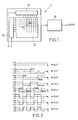
- FIG. 1 The overall structure of an image sensor according to an embodiment of the present invention is shown schematically in FIG. 1.
- This sensor 1 comprises a matrix 10 of photodetector elements intended to receive the light coming from an optical scene to be captured, and to transform the light received into electrical signals.
- a matrix 10 of photodetector elements intended to receive the light coming from an optical scene to be captured, and to transform the light received into electrical signals.
- FIG. 1 only part of the photodetector elements is shown.
- the photodetector elements can in particular be photodiodes or phototransistors.
- the matrix 10 can comprise as many rows as there are columns of photodetector elements.
- the photodetector element Pij located in the ith row and the jth column of a matrix having N rows and N columns, where N is a strictly positive integer and i and j are integers between 0 and N-1, receives a light flux L (i, j) and transforms it into an electric current signal denoted x (i, j).
- the rows of photodetector elements of the matrix 10 are connected to the inputs of a block 12 for generating and storing Walsh functions W (n, i), where n is an integer between 0 and N-1.
- W Walsh functions
- the columns of photodetector elements of the matrix 10 are connected to the inputs of a block 14 for generating and storing Walsh functions W (m, j), where m is an integer between 0 and N- 1.
- W m is an integer between 0 and N- 1.
- the output of a module comprising the matrix 10 of photodetector elements and the blocks 12 and 14 for generating and storing Walsh functions is connected to the input of a module 16 for weighting the electrical signals x (i, j ) by functions calculated from the set of Walsh functions W (n, i) and W (m, j), and summation of the weighted signals.
- the weighting and summing module 16 will be described in more detail below. It outputs NxN Walsh-Hadamard transform coefficients X (n, m) which represent the captured optical scene. The definition and the method of obtaining these coefficients will now be given.
- the optical scene to capture is arbitrary.
- radiometric parameters from the optical scene are measured in the form of NxN electrical signals x (i, j).
- the electrical signal x (i, j) is the collector current
- K (i, j) denotes the photoelectric conversion coefficient of the phototransistor Pij
- ⁇ (i, j) denotes the optical flux coming from the optical scene and picked up by the phototransistor Pij
- In (i, j) represents an intrinsic leakage current in the phototransistor.
- a weighting function Mnm (i, j), called the Walsh-Hadamard mask is generated for each signal x (i, j).
- n and m are integers between 0 and N-1.
- Each mask is worth either +1 or -1.
- FIG. 2 represents, by way of nonlimiting example, the first eight analog Walsh functions with one dimension, as a function of time t, ie W (0, t), W (1, t), ..., W (7, t), on N points.
- each mask can be represented by a checkerboard pattern composed of black portions and white portions.
- the NxN electrical signals x (i, j) are directly weighted by the NxN masks Mnm (i, j ) corresponding and adding the electrical signals thus weighted to obtain NxN Walsh-Hadamard transform coefficients X (n, m), each given by the formula and representing the optical scene captured.
- the electrical signals x (i, j) are weighted by the Mnm masks (i, j) and the summation of the weighted electrical signals by determining a component global positive C + and a global negative component C- of the current, the global positive component C + being the strictly positive sum, according to Kirchhoff's laws, of all the currents x (i, j) having for weighting function a mask Mnm (i , j) worth +1, and the global negative component C- being the strictly positive sum, according to Kirchhoff's laws, of all the currents x (i, j) having for weighting function a mask Mnm (i, j) being equal to -1.
- FIG. 4 is an electrical diagram which illustrates for any couple (n, m) the step which has just been described, namely, the separation of the currents coming from the photodetector elements Pij into two global components positive C + and negative C- .
- the corresponding mask Mnm (i, j) controls the switching of the current x (i, j), i.e. to a line 40 of contribution to the negative global component C-, i.e. towards a line 42 of contribution to the positive global component C +.
- the current x (i, j) comes from the photodetector element Pij, which has been represented diagrammatically in the form of a current generator generating the current x (i, j) and connected to ground.
- the image sensor already described in general with reference to FIG. 1 implements the above method.
- the blocks 12 and 14 and the module 16 of the sensor will now be described in detail, in a particular embodiment.
- FIG. 5A schematically represents the block 12 for generating and storing the N binary values respectively coding the N discrete Walsh functions of order n with one dimension, namely, W (n, i) for all i comprised between 0 and N -1.
- the block 12 comprises p (n) Walsh function generator modules, of identical structure, designated by 52 0 , ..., 52 r-1 , 52 r , ..., 52 p ( n) -1 , arranged in cascade, each having N parallel inputs and N parallel outputs.
- the p (n) modules having an identical structure, only the module 52 r , chosen arbitrarily, will be described in detail.
- 5A represent the arithmetic and logical part of the unit 53 carrying out the operation sgn [cos (K rn .2 r . ⁇ . i / N)] which provides, as described above, the value of f (r, n, i).
- the module 52 r also includes N OR-exclusive operators E r, 0 , ..., E r, N-1 .
- the first inputs of each of these operators are respectively connected to the outputs S r, 0 , ..., S r, N-1 of the calculation unit 53.
- the second inputs of each of the OR-exclusive operators E r, 0 , ..., E r, N-1 are respectively connected to the outputs of the N exclusive-OR operators E r-1,0 , ..., E r-1, N-1 of module 52 r-1 , except in the case of module 52 0 , arranged at the base of the cascade, where the second inputs of each of the exclusive-OR operators are supplied by a logic level "0" of initialization.
- the outputs of the N exclusive-OR operators of the module 52 p (n) -1 are respectively connected to the N inputs of a first suitable conventional digital memory (not shown), for example a ROM, which stores the N bits respectively encoding W ( n, 0), ..., W (n, N-1).
- Figure 5B is similar to Figure 5A. It will therefore only be described briefly. It schematically represents the block 14 for generating and storing the N binary values respectively coding the N discrete Walsh functions of order m with one dimension, namely, W (m, j) for all j between 0 and N-1 .
- Block 14 includes p (m) modules generating Walsh functions, of identical structure, designated by 54 0 , ..., 54 r-1 , 54 r , ..., 54 p (m) -1 , arranged in cascade and connected together in the same way as the modules 52 0 , ..., 52 r-1 , 52 r , ..., 52 p (n) -1 of Figure 5A and having the same structure as them.
- the module 54 r includes a calculation unit 55 which receives as input the bit K r, m defined above and calculates the binary value coding f (r, m, j) for all j between 0 and N-1.
- the second inputs of each of the exclusive-OR operators of the module 54 0 are supplied by a logic level "0" of initialization.
- the outputs of the N exclusive-OR operators of the module 54 p (m) -1 provide the N inputs with a suitable second conventional digital memory (not shown), for example a ROM, the N bits respectively coding W (m, 0), ..., W (m, N-1).
- FIG. 6 represents a part of the overall structure of the image sensor of the invention already illustrated by FIG. 1, in particular the block 12 for generating and storing Walsh functions W (n, i) and the block 14 of generation and memorization of Walsh functions W (m, j).
- FIG. 6 also represents, in an enlarged view, in a particular embodiment, the diagram of an electronic circuit generating a two-dimensional Walsh-Hadamard mask Mnm (i, j) from two discrete Walsh functions at one dimension, let W (n, i) and W (m, j).
- the electronic circuit comprises an OR-exclusive operator 60, whose first input is connected to the output line of block 12 leading to the crossover considered, and whose second input is connected to the output line of block 14 leading to this same crossing.
- the operator 60 therefore performs an OR-exclusive operation between the binary value coding W (n, i) and the binary value coding W (m, j), for a determined value of the couple (i, j), and outputs the binary value coding the mask Mnm (i, j).
- the mask Mnm (i, j) controls the switching of the current x (i, j) so as to provide a contribution to the weighted sum Walsh-Hadamard transform coefficient.
- the electronic diagram of FIG. 7 represents a complex switch 70 formed of a network of NMOS transistors, which simultaneously performs the OR-exclusive operation which has just been described and provides a contribution to the weighted sum of the set masks.
- the complex switch 70 comprises a first group of four NMOS transistors T1, T2, T3, T4.
- the gates of the transistors T1 to T4 are connected to the output of the memory contained in the block 12 for generating and storing Walsh functions W (n, i); the gates of transistors T1 and T2 receive the binary value coding W (n, i), and the gates of transistors T3 and T4 receive the logical inverse of this value, noted W (n, i) ⁇ , which can be achieved very simply by having an inverter at the corresponding output of said memory.
- the complex switch 70 also includes a second group of four NMOS transistors T5, T6, T7, T8.
- the gates of the transistors T5 to T8 are connected to the output of the memory contained in the block 14 for generating and memorizing Walsh functions W (m, j); the gates of transistors T5 and T6 receive the binary value coding W (m, j), and the gates of transistors T7 and T8 receive the logical inverse of this value, ie W (m, d) ⁇ , the reversal can be carried out as described above.
- the drains of the transistors T5 to T8 are connected to the output of the photodetector element Pij, shown in FIG. 7, in a particular embodiment, in the form of a photodiode.
- the drains of the T5 transistors at T8 are supplied by the current x (i, j).
- the sources of the transistors T5, T6, T7, T8 are respectively connected to the drains of the transistors T3, T1, T2, T4.
- the sources of transistors T1 and T3 constitute outputs, denoted "Plus”, of switch 70 where the current x (i, j) is assigned a positive conventional sense, and the sources of transistors T2 and T4 constitute outputs, denoted "Less”, of switch 70 where the current x (i, j) is affected in a negative conventional sense.
- NxN complex switches identical to the one just described are respectively connected to the outputs of block 14. All of these NxN switches form the weighting and summing module 16 mentioned in the description of FIG. 1.
- the image sensor comprises a VLSI circuit which combines the means described above and performs the operations mentioned above in real time.
- the present invention finds a particularly interesting, but not exclusive, application in the field of mobile radiocommunications, for portable devices requiring as low energy consumption as possible and a very small footprint, such as for example in videophone under the GSM standard ( Special Mobile Group). However, it could be used in other fields and in particular those of optical telesurveillance and television.
Landscapes
- Engineering & Computer Science (AREA)
- Physics & Mathematics (AREA)
- General Physics & Mathematics (AREA)
- Theoretical Computer Science (AREA)
- Mathematical Physics (AREA)
- Multimedia (AREA)
- Computational Mathematics (AREA)
- Mathematical Analysis (AREA)
- Mathematical Optimization (AREA)
- Pure & Applied Mathematics (AREA)
- Data Mining & Analysis (AREA)
- Signal Processing (AREA)
- General Engineering & Computer Science (AREA)
- Software Systems (AREA)
- Databases & Information Systems (AREA)
- Algebra (AREA)
- Computer Vision & Pattern Recognition (AREA)
- Complex Calculations (AREA)
- Compression, Expansion, Code Conversion, And Decoders (AREA)
- Compression Of Band Width Or Redundancy In Fax (AREA)
Abstract
Description
La présente invention concerne un procédé pour fournir une représentation d'une scène optique par transformation de Walsh-Hadamard, et un capteur d'image mettant en oeuvre ce procédé. Ces dernières années, les réseaux informatiques et les technologies multimédia ont connu un développement rapide. La compression de données est donc devenue un enjeu majeur. En particulier, de nombreux procédés de codage ont vu le jour dans le domaine de la compression des images. Parmi les procédés utilisés, les codages par transformation orthogonale permettent d'obtenir, à qualité d'image égale, des taux de compression supérieurs à ceux obtenus par des procédés du type à prédiction linéaire. De plus, les systèmes de codage par transformation orthogonale sont nettement moins sensibles aux erreurs, de transmission par exemple, que les systèmes à prédiction.The present invention relates to a method for providing a representation of an optical scene by Walsh-Hadamard transformation, and an image sensor implementing this method. In recent years, computer networks and multimedia technologies have experienced rapid development. Data compression has therefore become a major issue. In particular, numerous coding methods have emerged in the field of image compression. Among the methods used, codings by orthogonal transformation make it possible to obtain, at equal image quality, compression rates higher than those obtained by methods of the linear prediction type. In addition, orthogonal transformation coding systems are much less sensitive to errors, for example transmission errors, than prediction systems.
Si de très nombreuses transformations ont été étudiées, seules quelques-unes sont actuellement effectivement utilisées : la transformation de Karhunen-Loève, qui en théorie fournit les meilleurs résultats, mais reste difficile à mettre en oeuvre; la transformation en cosinus discret (DCT), qui constitue une bonne approximation de la transformation de Karhunen-Loève qui est retenue par un certain nombre de normalisations, et dont la mise en oeuvre est plus facile; et la transformation de Walsh-Hadamard, bien adaptée aux calculateurs numériques.If very many transformations have been studied, only a few are currently actually used: the Karhunen-Loève transformation, which in theory provides the best results, but remains difficult to implement; the transformation in discrete cosine (DCT), which constitutes a good approximation of the transformation of Karhunen-Loève which is retained by a certain number of normalizations, and whose implementation is easier; and the Walsh-Hadamard transformation, well suited to digital computers.
Cette dernière transformation consiste, comme la transformation de Fourier, en une décomposition du signal considéré sur un ensemble de vecteurs de base orthogonaux. La transformation de Walsh-Hadamard peut par ailleurs être appliquée à des signaux multidimensionnels. A la différence de la transformation de Fourier, elle utilise pour la décomposition du signal considéré un ensemble de vecteurs non sinusoïdaux.This last transformation consists, like the Fourier transformation, in a decomposition of the signal considered on a set of orthogonal basic vectors. The Walsh-Hadamard transformation can also be applied to multidimensional signals. Unlike the Fourier transformation, it uses for the decomposition of the signal considered a set of non-sinusoidal vectors.
La présente invention a pour objet un procédé et un capteur d'image intégrant un module qui met en oeuvre la transformation de Walsh-Hadamard, afin de fournir en sortie, non pas des valeurs de niveaux de gris associés à des éléments d'image, ou pixels, de l'image transformée, mais directement les valeurs des coefficients de la transformée de Walsh-Hadamard d'une scène optique captée.The subject of the present invention is a method and an image sensor integrating a module which implements the Walsh-Hadamard transformation, in order to provide as an output, not gray level values associated with image elements, or pixels, of the transformed image, but directly the values of the coefficients of the Walsh-Hadamard transform of a captured optical scene.
Les capteurs d'image classiques mettent en oeuvre un procédé de codage où : on capte une scène optique sous forme d'un signal analogique, qu'on appellera l'image captée; on transforme l'image captée en une image numérique; on lit et on mémorise les valeurs de niveaux de gris de la totalité des éléments d'image numérique; on applique à l'image numérique une transformation, qui peut être la transformation de Walsh-Hadamard; et on sous-échantillonne le signal d'image transformée afin de reconstruire l'image captée. Les procédés utilisés comportent une succession très longue d'étapes coûteuses en temps de calcul. Les capteurs d'image de l'art antérieur nécessitent donc l'utilisation de composants électroniques très rapides et donc chers, pour ne pas exiger un compromis entre le temps de calcul et la résolution de l'image.Conventional image sensors use a coding method where: an optical scene is captured in the form of an analog signal, which will be called the captured image; the captured image is transformed into a digital image; the gray level values of all the digital picture elements are read and stored; a transformation is applied to the digital image, which can be the Walsh-Hadamard transformation; and the transformed image signal is sub-sampled in order to reconstruct the captured image. The methods used include a very long succession of steps which are costly in computation time. The image sensors of the prior art therefore require the use of very fast and therefore expensive electronic components, so as not to require a compromise between the computation time and the resolution of the image.
Dans le but de remédier à ces inconvénients, la présente invention propose un procédé pour fournir une représentation d'une scène optique par transformation de Walsh-Hadamard, suivant lequel :
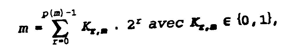
- (a) on mesure des paramètres radiométriques de NxN points représentant une scène optique réelle à deux dimensions sous forme de NxN signaux électriques respectifs x(i,j), où N est un entier strictement positif, et i et j sont des entiers compris entre 0 et N-1, représentant lesdites deux dimensions;
- (b) on engendre NxN fonctions de pondération, dites masques, respectivement associées aux NxN signaux électriques x(i,j), ces fonctions ne prenant que la valeur +1 ou - 1, et étant notées Mnm(i,j), où n et m sont des entiers compris entre 0 et N-1, chaque masque étant obtenu par la formule :


- où r est un entier,
- où b est un entier compris entre 0 et N-1,
- où a est un entier tel que

- où p(a) est le nombre de chiffres binaires pour écrire l'entier a en
base 2, - où est le signe "produit",

- et sgn est la fonction définie par sgn(x) = +1 si x≥0 et sgn(x) = -1 si x<0;
- (c) pour chaque couple (n,m), on pondère directement lesdits NxN signaux électriques x(i,j) par lesdits NxN masques Mnm(i,j) correspondants et on additionne les signaux électriques pondérés pour obtenir NxN coefficients de transformée de Walsh-Hadamard X(n,m), donnés chacun par la formule

- (a) measuring radiometric parameters of NxN points representing a real two-dimensional optical scene in the form of NxN respective electrical signals x (i, j), where N is a strictly positive integer, and i and j are integers between 0 and N-1, representing said two dimensions;
- (b) one generates NxN weighting functions, called masks, respectively associated with NxN electrical signals x (i, j), these functions only taking the value +1 or - 1, and being denoted Mnm (i, j), where n and m are integers between 0 and N-1, each mask being obtained by the formula :
- where r is an integer,
- where b is an integer between 0 and N-1,
- where a is an integer such that
- where p (a) is the number of binary digits to write the integer a in
base 2, - or is the sign "product",
- and sgn is the function defined by sgn (x) = +1 if x≥0 and sgn (x) = -1 if x <0;
- (c) for each pair (n, m), said NxN electrical signals x (i, j) are directly weighted by said corresponding NxN masks Mnm (i, j) and the weighted electrical signals are added to obtain NxN transform coefficients of Walsh-Hadamard X (n, m), each given by the formula
La présente invention propose également un capteur d'image mettant en oeuvre le procédé de codage ci-dessus, ce capteur comprenant :
- NxN moyens photodétecteurs agencés sous forme d'une matrice à N rangées et N colonnes, pour transformer un signal lumineux L(i,j), 0≤i≤N-1, 0≤j≤N-1, reçu en provenance de la scène optique dans la ième rangée et la jième colonne, en un signal de courant électrique x(i,j),
- p(n) premiers moyens générateurs de fonction de Walsh, numérotés par leur rang r, 0≤r≤p(n)-1, qui comprennent chacun
- des moyens de calcul qui reçoivent le bit Kr,n en entrée, calculent la valeur de f(r,n,i) pour tout i, 0≤i≤N-1, et fournissent en sortie le bit "0" si f(r,n,i) = +1 ou le bit "1" si f(r,n,i) = -1, et
- N opérateurs OU-exclusif disposés en parallèle, une première entrée de chacun des N opérateurs de rang r≥0 étant connectée à la sortie desdits moyens de calcul, et une seconde entrée de chacun des N opérateurs de rang r≥1 étant respectivement connectée à la sortie correspondante de chacun des N opérateurs OU-exclusif de rang r-1, la seconde entrée de chacun des N opérateurs de rang r = 0 étant alimentée par un niveau logique "0" d'initialisation,
- les N opérateurs OU-exclusif de rang r = p(n)-1 fournissant en sortie N bits codant les N fonctions de Walsh W(n,i) pour tout i, 0≤i≤N-1, à savoir, valant 0 si W(n,i) = +1 ou valant 1 si W(n,i) = -1;
- des premiers moyens de mémoire, comprenant N entrées respectivement connectées aux N sorties des premiers moyens générateurs de rang p(n)-1, pour mémoriser la valeur de W(n,i) pour tout i, 0≤1≤N-1;
- p(m) seconds moyens générateurs de fonction de Walsh, numérotés par leur rang r, 0≤r≤p(m)-1, qui comprennent chacun
- des moyens de calcul qui reçoivent le bit Kr,m en entrée, calculent la valeur de f(r,m,j) pour tout j, 0≤j≤N-1, et fournissent en sortie le bit "0" si f(r,m,j) = +1 ou le bit "1" si f(r,m,j) = -1, et
- N opérateurs OU-exclusif disposés en parallèle, une première entrée de chacun des N opérateurs de rang r≥0 étant connectée à la sortie desdits moyens de calcul, et une seconde entrée de chacun des N opérateurs de rang r≥1 étant respectivement connectée à la sortie correspondante de chacun des N opérateurs de rang r-1, la seconde entrée de chacun des N opérateurs de rang r = 0 étant alimentée par un niveau logique "0" d'initialisation,
- les N opérateurs OU-exclusif de rang r = p(m)-1 fournissant en sortie N bits codant les N fonctions de Walsh W(m,j) pour tout , 0≤j≤N-1, à savoir, valant 0 si W(m,j) = +1 ou valant 1 si W(m,j) = -1; et
- des seconds moyens de mémoire, comprenant N entrées respectivement connectées aux N sorties des seconds moyens générateurs de rang p(m)-1, pour mémoriser la valeur de W(m,j) pour tout j, 0≤j≤N-1; et
- NxN éléments à état solide connectés respectivement à l'une des N sorties des premiers moyens de mémoire et à l'une des N sorties des seconds moyens de mémoire, lesquels NxN éléments à état solide calculent respectivement la valeur de la variable binaire codant l'un des NxN masques de Walsh-Hadamard Mnm(i,j) et affectent le courant x(i,j) correspondant d'un sens conventionnel positif ou négatif suivant le niveau logique de la variable binaire codant Mnm(i,j), la sommation selon les lois de Kirchhoff des courants ainsi obtenus fournissant en sortie NxN coefficients de transformée de Walsh-Hadamard X(n,m), 0≤n≤N-1, 0≤m≤N-1, de la scène optique captée.
- NxN photodetector means arranged in the form of a matrix with N rows and N columns, for transforming a light signal L (i, j), 0≤i≤N-1, 0≤j≤N-1, received from the optical scene in the ith row and the jth column, in an electric current signal x (i, j),
- p (n) first Walsh function generating means, numbered by their rank r, 0≤r≤p (n) -1, which each include
- calculation means which receive the bit K r, n at input, calculate the value of f (r, n, i) for all i, 0≤i≤N-1, and output the bit "0" if f (r, n, i) = +1 or the bit "1" if f (r, n, i) = -1, and
- N OR-exclusive operators arranged in parallel, a first input of each of the N operators of rank r≥0 being connected to the output of said calculation means, and a second input of each of the N operators of rank r≥1 being respectively connected to the corresponding output of each of the N exclusive OR operators of rank r-1, the second input of each of the N operators of rank r = 0 being supplied by a logic initialization level "0",
- the N exclusive-OR operators of rank r = p (n) -1 providing as output N bits coding the N functions of Walsh W (n, i) for all i, 0≤i≤N-1, namely, being 0 if W (n, i) = +1 or equal to 1 if W (n, i) = -1;
- first memory means, comprising N inputs respectively connected to the N outputs of the first generating means of rank p (n) -1, for storing the value of W (n, i) for all i, 0≤1≤N-1;
- p (m) second Walsh function generating means, numbered by their rank r, 0≤r≤p (m) -1, which each include
- computing means which receive the bit K r, m at input, calculate the value of f (r, m, j) for all j, 0≤j≤N-1, and output the bit "0" if f (r, m, j) = +1 or the bit "1" if f (r, m, j) = -1, and
- N OR-exclusive operators arranged in parallel, a first input of each of the N operators of rank r≥0 being connected to the output of said calculation means, and a second input of each of the N operators of rank r≥1 being respectively connected to the corresponding output of each of the N operators of rank r-1, the second input of each of the N operators of rank r = 0 being supplied by a logic level "0" of initialization,
- the N exclusive-OR operators of rank r = p (m) -1 providing as output N bits coding the N functions of Walsh W (m, j) for all, 0≤j≤N-1, namely, being 0 if W (m, j) = +1 or worth 1 if W (m, j) = -1; and
- second memory means, comprising N inputs respectively connected to the N outputs of the second generator means of rank p (m) -1, for storing the value of W (m, j) for all j, 0≤j≤N-1; and
- NxN solid state elements connected respectively to one of the N outputs of the first memory means and to one of the N outputs of the second memory means, which NxN solid state elements respectively calculate the value of the binary variable coding for one of the NxN masks of Walsh-Hadamard Mnm (i, j) and affect the current x (i, j) corresponding in a positive or negative conventional sense depending on the logical level of the binary variable coding Mnm (i, j), the summation according to Kirchhoff's laws of the currents thus obtained providing at output NxN Walsh-Hadamard transform coefficients X (n, m), 0≤n≤N-1, 0≤m≤N-1, of the captured optical scene.
Les caractéristiques ci-dessus ainsi que d'autres apparaîtront mieux à la lecture de la description qui suit d'un mode particulier de réalisation de l'invention donné à titre d'exemple non limitatif et d'une variante. La description se réfère aux dessins qui l'accompagnent, dans lesquels:
- la figure 1 est un schéma représentant la structure globale d'un capteur d'image selon la présente invention;
- la figure 2 est un ensemble de courbes représentant les huit premières fonctions de Walsh-Hadamard;
- la figure 3 représente les seize masques de pondération de Walsh-Hadamard associés à une transformation sur une image carrée de 4 x 4 pixels;
- la figure 4 est un schéma électrique représentant sous forme symbolique une étape du calcul des coefficients de transformée de Walsh-Hadamard par sommation de courants, dans un mode particulier de réalisation;
- les figures 5A et 5B sont des schémas symboliques représentant, dans un mode particulier de réalisation, un réseau de composants électroniques en cascade engendrant des fonctions de Walsh discrètes à une dimension;
- la figure 6 est un schéma représentant, en vue partiellement agrandie, dans un mode particulier de réalisation, un circuit électronique engendrant un masque de Walsh-Hadamard à deux dimensions à partir de deux fonctions de Walsh discrètes à une dimension;
- la figure 7 est un schéma électronique représentant un commutateur complexe formé d'un réseau de transistors NMOS, qui produit simultanément un masque de Walsh-Hadamard et une contribution à la somme pondérée de l'ensemble des masques.
- Figure 1 is a diagram showing the overall structure of an image sensor according to the present invention;
- FIG. 2 is a set of curves representing the first eight Walsh-Hadamard functions;
- FIG. 3 represents the sixteen Walsh-Hadamard weighting masks associated with a transformation on a square image of 4 x 4 pixels;
- FIG. 4 is an electrical diagram representing in symbolic form a step in the calculation of the Walsh-Hadamard transform coefficients by summation of currents, in a particular embodiment;
- FIGS. 5A and 5B are symbolic diagrams representing, in a particular embodiment, a network of electronic components in cascade generating discrete one-dimensional Walsh functions;
- FIG. 6 is a diagram showing, in partially enlarged view, in a particular embodiment, an electronic circuit generating a two-dimensional Walsh-Hadamard mask from two discrete one-dimensional Walsh functions;
- FIG. 7 is an electronic diagram representing a complex switch formed by a network of NMOS transistors, which simultaneously produces a Walsh-Hadamard mask and a contribution to the weighted sum of all the masks.
La structure globale d'un capteur d'image conforme à un mode de réalisation de la présente invention est représentée de façon schématique sur la figure 1.The overall structure of an image sensor according to an embodiment of the present invention is shown schematically in FIG. 1.
Ce capteur 1 comprend une matrice 10 d'éléments photodétecteurs prévus pour recevoir la lumière provenant d'une scène optique à capter, et pour transformer la lumière reçue en des signaux électriques. Sur la figure 1, une partie seulement des éléments photodétecteurs est représentée. Les éléments photodétecteurs peuvent notamment être des photodiodes ou des phototransistors.This
La matrice 10 peut comprendre autant de rangées que de colonnes d'éléments photodétecteurs. Par exemple, l'élément photodétecteur Pij situé dans la ième rangée et la jième colonne d'une matrice ayant N rangées et N colonnes, où N est un entier strictement positif et i et j sont des entiers compris entre 0 et N-1, reçoit un flux lumineux L(i,j) et le transforme en un signal de courant électrique noté x(i,j).The
Les rangées d'éléments photodétecteurs de la matrice 10 sont connectées aux entrées d'un bloc 12 de génération et de mémorisation de fonctions de Walsh W(n,i), où n est un entier compris entre 0 et N-1. La structure détaillée du bloc 12 sera décrite plus tard.The rows of photodetector elements of the
De façon similaire, les colonnes d'éléments photodétecteurs de la matrice 10 sont connectées aux entrées d'un bloc 14 de génération et de mémorisation de fonctions de Walsh W(m,j), où m est un entier compris entre 0 et N-1. La structure détaillée du bloc 14 sera également décrite plus tard.Similarly, the columns of photodetector elements of the
La sortie d'un module comprenant la matrice 10 d'éléments photodétecteurs et les blocs 12 et 14 de génération et de mémorisation de fonctions de Walsh est connectée à l'entrée d'un module 16 de pondération des signaux électriques x(i,j) par des fonctions calculées à partir de l'ensemble des fonctions de Walsh W(n,i) et W(m,j), et de sommation des signaux pondérés.The output of a module comprising the
Le module 16 de pondération et de sommation sera décrit plus en détail ci-après. Il fournit en sortie NxN coefficients de transformée de Walsh-Hadamard X(n,m) qui représentent la scène optique captée. La définition et le procédé d'obtention de ces coefficients vont maintenant être donnés.The weighting and summing
La scène optique à capter est quelconque. Au cours d'une première étape, on mesure des paramètres radiométriques provenant de la scène optique sous forme de NxN signaux électriques x(i,j).The optical scene to capture is arbitrary. During a first step, radiometric parameters from the optical scene are measured in the form of NxN electrical signals x (i, j).
Dans un mode de réalisation où l'acquisition de la scène optique se fait au moyen d'une matrice 10 de NxN photodiodes, le signal électrique x(i,j) est le courant inverse Id(i,j) qui traverse la photodiode Pij située dans la ième rangée et la jième colonne, et vaut Id(i,j) = K(i,j) x φ(i,j) + In(i,j), où K(i,j) désigne le coefficient de conversion photoélectrique de la photodiode Pij, φ(i,j) désigne le flux optique issu de la scène optique et capté par la photodiode Pij, et In(i,j) représente un courant de fuite intrinsèque dans la photodiode Pij, appelé courant d'obscurité.In an embodiment where the acquisition of the optical scene is done by means of a
Dans un autre mode de réalisation, où l'acquisition de la scène optique se fait au moyen d'une matrice 10 de NxN phototransistors, le signal électrique x(i,j) est le courant collecteur, K(i,j) désigne le coefficient de conversion photoélectrique du phototransistor Pij, φ(i,j) désigne le flux optique issu de la scène optique et capté par le phototransistor Pij, et In(i,j) représente un courant de fuite intrinsèque dans le phototransistor.In another embodiment, where the acquisition of the optical scene is done by means of a
Au cours d'une deuxième étape, on engendre pour chaque signal x(i,j) une fonction de pondération Mnm(i,j), dite masque de Walsh-Hadamard. n et m sont des entiers compris entre 0 et N-1. Chaque masque vaut soit +1, soit -1. Pour obtenir le masque Mnm(i,j), on engendre tout d'abord une fonction de Walsh discrète à une dimension W(n,i), d'ordre n sur N points. On engendre cette fonction à partir de l'équation
![]()

![]()
![]()
![]()
Toujours au cours de la deuxième étape, on engendre également une fonction de Walsh discrète à une dimension W(m,j), d'ordre m sur N points. On engendre cette fonction, de façon analogue à ce qui précède, à partir de l'équation
![]()
![]()
On obtient alors chaque masque Mnm(i,j) grâce à la formule :![]()
![]()
En termes de représentation d'images en noir et blanc, si on associe la valeur + 1 d'un masque au "noir" (niveau de gris le plus élevé) et la valeur -1 d'un masque au "blanc" (niveau de gris le plus bas), on peut représenter chaque masque par un motif en damier composé de portions noires et de portions blanches. La figure 3 représente à titre d'exemple les seize masques de pondération en damier pour N = 4. On a indiqué en dessous de chaque masque le couple (n,m) correspondant.In terms of representation of black and white images, if we associate the value + 1 of a mask with "black" (highest gray level) and the value -1 of a mask with "white" (level lowest gray), each mask can be represented by a checkerboard pattern composed of black portions and white portions. FIG. 3 represents by way of example the sixteen checkered weighting masks for N = 4. The corresponding couple (n, m) has been indicated below each mask.
Au cours d'une troisième étape du procédé selon un mode de réalisation de l'invention, pour chaque couple (n,m), on pondère directement les NxN signaux électriques x(i,j) par les NxN masques Mnm(i,j) correspondants et on additionne les signaux électriques ainsi pondérés pour obtenir NxN coefficients de transformée de Walsh-Hadamard X(n,m), donnés chacun par la formule
Les deuxième et troisième étapes du procédé vont maintenant être décrites plus en détail dans le cadre d'un mode particulier de réalisation. Il est clair, d'après les formules permettant d'obtenir les grandeurs décimales sgn, f, W et Mnm, que toutes ces grandeurs prennent uniquement la valeur +1 ou la valeur -1. Dans le mode particulier de réalisation qui va maintenant être décrit, on code toutes ces grandeurs par des variables binaires ayant le niveau logique "0" si la grandeur décimale correspondante vaut +1, ou le niveau logique "1" si la grandeur décimale correspondante vaut -1. Une multiplication de deux des grandeurs décimales codées se traduit par conséquent par une opération logique OU-exclusif.The second and third steps of the method will now be described in more detail in the context of a particular embodiment. It is clear, from the formulas allowing to obtain the decimal quantities sgn, f, W and Mnm, that all these quantities take only the value +1 or the value -1. In the particular embodiment which will now be described, all these quantities are coded by binary variables having the logic level "0" if the corresponding decimal quantity is worth +1, or the logic level "1" if the corresponding decimal quantity is worth -1. A multiplication of two of the coded decimal quantities consequently results in an OR-exclusive logical operation.
Au cours de la deuxième étape décrite précédemment, on effectue alors pour chaque coupe (i,j), 0≤i≤N-1, 0≤j≤N-1, les étapes suivantes :During the second step described above, the following steps are then carried out for each cut (i, j), 0≤i≤N-1, 0≤j≤N-1:
Pour obtenir la valeur de la variable binaire codant la grandeur décimale W(n,i), on effectue une itération suivant laquelle, successivement :
- on initialise la variable binaire codant W(n,i) au niveau logique "0";
- on initialise l'entier r défini précédemment à la valeur 0;
- pour chaque valeur de r, on effectue une opération OU-exclusif entre la variable binaire actuelle codant W(n,i) et la variable binaire codant la grandeur décimale f(r,n,i) préalablement obtenue à partir de l'équation donnée plus haut, on réactualise la variable binaire codant W(n,i) au niveau logique obtenu après l'opération OU-exclusif, puis on
incrémente r de 1;
- the binary variable coding W (n, i) is initialized at logic level "0";
- the integer r defined above is initialized to the
value 0; - for each value of r, an OR-exclusive operation is performed between the current binary variable coding W (n, i) and the binary variable coding the decimal quantity f (r, n, i) previously obtained from the equation given above, the binary variable coding W (n, i) is updated at the logical level obtained after the OR-exclusive operation, then increment r by 1;
Pour obtenir la valeur de la variable binaire codant W(m,j), on effectue une itération similaire, à savoir, successivement :
- on initialise la variable binaire codant W(m,j) au niveau logique "0";
- on initialise l'entier r à la valeur 0;
- pour chaque valeur de r, on effectue une opération OU-exclusif entre la variable binaire actuelle codant W(m,j) et la variable binaire codant la grandeur décimale f(r,m,j) préalablement obtenue à partir de l'équation donnée plus haut, on réactualise la variable binaire codant W(m,j) au niveau logique obtenu après l'opération OU-exclusif, puis on
incrémente r de 1;
- the binary variable coding W (m, j) is initialized at logic level "0";
- we initialize the integer r to the
value 0; - for each value of r, an OR-exclusive operation is carried out between the current binary variable coding W (m, j) and the binary variable coding the decimal quantity f (r, m, j) previously obtained from the given equation above, the binary variable coding W (m, j) is updated to the logical level obtained after the OR-exclusive operation, then increment r by 1;
Pour obtenir la valeur de la variable binaire codant Mnm (i,j), on effectue une opération OU-exclusif entre les variables binaires codant respectivement W(n,i) et W(m,j).To obtain the value of the binary variable coding Mnm (i, j), an OR-exclusive operation is performed between the binary variables coding W (n, i) and W (m, j) respectively.
Au cours de la troisième étape décrite précédemment, et dans un mode particulier de réalisation, on réalise la pondération des signaux électriques x(i,j) par les masques Mnm(i,j) et la sommation des signaux électriques pondérés en déterminant une composante positive globale C+ et une composante négative globale C- du courant, la composante positive globale C+ étant la somme strictement positive, selon les lois de Kirchhoff, de tous les courants x(i,j) ayant pour fonction de pondération un masque Mnm(i,j) valant +1, et la composante négative globale C- étant la somme strictement positive, selon les lois de Kirchhoff, de tous les courants x(i,j) ayant pour fonction de pondération un masque Mnm(i,j) valant -1.During the third step described above, and in a particular embodiment, the electrical signals x (i, j) are weighted by the Mnm masks (i, j) and the summation of the weighted electrical signals by determining a component global positive C + and a global negative component C- of the current, the global positive component C + being the strictly positive sum, according to Kirchhoff's laws, of all the currents x (i, j) having for weighting function a mask Mnm (i , j) worth +1, and the global negative component C- being the strictly positive sum, according to Kirchhoff's laws, of all the currents x (i, j) having for weighting function a mask Mnm (i, j) being equal to -1.
A cet effet, pour chaque couple (n,m), 0≤n≤N-1, 0≤m≤N-1 :
- on regroupe les entiers i, 0≤i≤N-1, en deux ensembles I+ et I-, et on regroupe les entiers j, 0≤j≤N-1, en deux ensembles J+ et J-, de façon que
∀i∈I+, ∀j∈J+, Mnm(i,j) = + 1 et
∀i∈I-, ∀j∈J-, Mnm(i,j) = -1; - en appliquant les lois de Kirchhoff, on additionne, d'une part, les courants x(i,j) pour lesquels i et j sont respectivement inclus dans les ensembles I+ et J+, et, d'autre part, les courants x(i,j) pour lesquels i et j sont respectivement inclus dans les ensembles I- et J-, de façon à obtenir la composante positive globale du courant
et la composante négative globale du courant
- on soustrait le courant C- au courant C+, ce qui fournit le coefficient de transformée de Walsh-Hadamard X(n,m) = C+ - C-.
- the integers i, 0≤i≤N-1 are grouped into two sets I + and I-, and the integers j, 0≤j≤N-1 are grouped into two sets J + and J-, so that
∀i∈I +, ∀j∈J +, Mnm (i, j) = + 1 and
∀i∈I-, ∀j∈J-, Mnm (i, j) = -1; - by applying Kirchhoff's laws, we add, on the one hand, the currents x (i, j) for which i and j are respectively included in the sets I + and J +, and, on the other hand, the currents x (i , j) for which i and j are respectively included in the sets I- and J-, so as to obtain the overall positive component of the current
and the overall negative component of the current - we subtract current C- from current C +, which provides the Walsh-Hadamard transform coefficient X (n, m) = C + - C-.
La figure 4 est un schéma électrique qui illustre pour un couple (n,m) quelconque l'étape qui vient d'être décrite, à savoir, la séparation des courants issus des éléments photodétecteurs Pij en deux composantes globales positive C+ et négative C-.FIG. 4 is an electrical diagram which illustrates for any couple (n, m) the step which has just been described, namely, the separation of the currents coming from the photodetector elements Pij into two global components positive C + and negative C- .
Pour chaque couple (i,j), 0≤i≤N-1, 0≤j≤N-1, le masque Mnm(i,j) correspondant commande la commutation du courant x(i,j), soit vers une ligne 40 de contribution à la composante globale négative C-, soit vers une ligne 42 de contribution à la composante globale positive C+. Le courant x(i,j) est issu de l'élément photodétecteur Pij, qu'on a représenté schématiquement sous la forme d'un générateur de courant engendrant le courant x(i,j) et connecté à la masse.For each pair (i, j), 0≤i≤N-1, 0≤j≤N-1, the corresponding mask Mnm (i, j) controls the switching of the current x (i, j), i.e. to a
Le choix des positions de commutation sur la figure 4 est arbitraire.The choice of switching positions in Figure 4 is arbitrary.
On additionne entre eux tous les courants commutés vers la ligne 40, pour obtenir la composante C-, et on additionne entre eux tous les courants commutés vers la ligne 42, pour obtenir la composante C+. L'étape ultérieure de soustraction C+ - C-, non représentée sur la figure 4, peut être effectuée à l'intérieur ou à l'extérieur du capteur d'image mettant en oeuvre le procédé décrit ici, par exemple, au moyen d'un simple amplificateur opérationnel.We add together all the currents switched to
Le capteur d'image déjà décrit de façon globale en se référant à la figure 1 met en oeuvre le procédé ci-dessus. Les blocs 12 et 14 et le module 16 du capteur vont maintenant être décrits de façon détaillée, dans un mode particulier de réalisation.The image sensor already described in general with reference to FIG. 1 implements the above method. The
La figure 5A représente schématiquement le bloc 12 de génération et de mémorisation des N valeurs binaires codant respectivement les N fonctions de Walsh discrètes d'ordre n à une dimension, à savoir, W(n,i) pour tout i compris entre 0 et N-1.FIG. 5A schematically represents the
Comme le montre la figure 5A, le bloc 12 comprend p(n) modules générateurs de fonction de Walsh, de structure identique, désignés par 520,..., 52r-1,52r,...,52p(n)-1, disposés en cascade, ayant chacun N entrées parallèles et N sorties parallèles. Les p(n) modules ayant une structure identique, seul le module 52r, choisi arbitrairement, sera décrit en détail.As shown in FIG. 5A, the
Il comprend une unité de calcul 53 ayant N entrées parallèles, qui reçoit sur chacune de ces entrées le bit Kr,n défini plus haut, calcule la valeur binaire codant f(r,n,i) pour tout i compris entre 0 et N-1 à partir de l'équation donnée plus haut, à savoir, produit "0" si f(r,n,i) = +1 et produit "1" si f(r,n,i) = -1, et fournit les N bits de résultat sur ses N sorties parallèles Sr,0,..., Sr,N-1. Les éléments C0,...,CN-1 de l'unité 53 représentés sur la figure 5A représentent la partie arithmétique et logique de l'unité 53 effectuant l'opération sgn[cos(Kr.n.2r.π.i/N)] qui fournit, comme décrit précédemment, la valeur de f(r,n,i).It includes a
Le module 52r comprend en outre N opérateurs OU-exclusif Er,0,...,Er,N-1. Les premières entrées de chacun de ces opérateurs sont connectées respectivement aux sorties Sr,0,...,Sr,N-1 de l'unité de calcul 53. Les secondes entrées de chacun des opérateurs OU-exclusif Er,0,...,Er,N-1 sont connectées respectivement aux sorties des N opérateurs OU-exclusif Er-1,0,...,Er-1,N-1 du module 52r-1, sauf dans le cas du module 520, disposé à la base de la cascade, où les secondes entrées de chacun des opérateurs OU-exclusif sont alimentées par un niveau logique "0" d'initialisation.The module 52 r also includes N OR-exclusive operators E r, 0 , ..., E r, N-1 . The first inputs of each of these operators are respectively connected to the outputs S r, 0 , ..., S r, N-1 of the
Dans le module 52p(n)-1, disposé au sommet de la cascade, les sorties des N opérateurs OU-exclusif fournissent N bits codant respectivement les N fonctions de Walsh W(n,i), 0≤i≤N-1, à savoir, fournissent le bit 0 si W(n,i) = +1 ou le bit 1 si W(n,i) = -1. Les sorties des N opérateurs OU-exclusif du module 52p(n)-1 sont connectées respectivement aux N entrées d'une première mémoire numérique classique appropriée (non représentée), par exemple une ROM, qui mémorise les N bits codant respectivement W(n,0),..., W(n,N-1).In the module 52 p (n) -1 , arranged at the top of the cascade, the outputs of the N exclusive-OR operators provide N bits respectively coding the N Walsh functions W (n, i), 0≤i≤N-1 , i.e., provide
La figure 5B est analogue à la figure 5A. Elle ne sera donc décrite que brièvement. Elle représente schématiquement le bloc 14 de génération et de mémorisation des N valeurs binaires codant respectivement les N fonctions de Walsh discrètes d'ordre m à une dimension, à savoir, W(m,j) pour tout j compris entre 0 et N-1.Figure 5B is similar to Figure 5A. It will therefore only be described briefly. It schematically represents the
Le bloc 14 comprend p(m) modules générateurs de fonctions de Walsh, de structure identique, désignés par 540,...,54r-1,54r,...,54p(m)-1, disposés en cascade et connectés entre eux de la même façon que les modules 520,..., 52r-1,52r,...,52p(n)-1 de la figure 5A et ayant la même structure qu'eux. De même que le module 52r décrit précédemment, le module 54r comprend une unité de calcul 55 qui reçoit en entrée le bit Kr,m défini plus haut et calcule la valeur binaire codant f(r,m,j) pour tout j compris entre 0 et N-1.
De même que pour le module 520, les secondes entrées de chacun des opérateurs OU-exclusif du module 540 sont alimentées par un niveau logique "0" d'initialisation.As for the module 52 0 , the second inputs of each of the exclusive-OR operators of the
De même que pour le module 52p(n)-1, les sorties des N opérateurs OU-exclusif du module 54p(m)-1 fournissent aux N entrées d'une seconde mémoire numérique classique appropriée (non représentée), par exemple une ROM, les N bits codant respectivement W(m,0),...,W(m,N-1).As for the module 52 p (n) -1 , the outputs of the N exclusive-OR operators of the
La figure 6 représente une partie de la structure globale du capteur d'image de l'invention déjà illustrée par la figure 1, en particulier le bloc 12 de génération et de mémorisation de fonctions de Walsh W(n,i) et le bloc 14 de génération et de mémorisation de fonctions de Walsh W(m,j). La figure 6 représente en outre, en vue agrandie, dans un mode particulier de réalisation, le schéma d'un circuit électronique engendrant un masque de Walsh-Hadamard à deux dimensions Mnm(i,j) à partir de deux fonctions de Walsh discrètes à une dimension, soit W(n,i) et W(m,j).FIG. 6 represents a part of the overall structure of the image sensor of the invention already illustrated by FIG. 1, in particular the
Ce circuit électronique est disposé à un croisement d'une ligne de sortie du bloc 12 et d'une ligne de sortie du bloc 14. NxN circuits électroniques identiques sont ainsi disposés aux NxN croisements entre les N lignes de sortie du bloc 14. Dans un mode particulier de réalisation, le circuit électronique comprend un opérateur OU-exclusif 60, dont une première entrée est connectée à la ligne de sortie du bloc 12 aboutissant au croisement considéré, et dont la seconde entrée est connectée à la ligne de sortie du bloc 14 aboutissant à ce même croisement. L'opérateur 60 effectue donc une opération OU-exclusif entre la valeur binaire codant W(n,i) et la valeur binaire codant W(m,j), pour une valeur déterminée du couple (i,j), et fournit en sortie la valeur binaire codant le masque Mnm(i,j). Comme décrit précédemment à l'aide de la figure 4, le masque Mnm(i,j) commande alors la commutation du courant x(i,j) de façon à fournir une contribution à la somme pondérée
Le schéma électronique de la figure 7 représente un commutateur complexe 70 formé d'un réseau de transistors NMOS, qui, simultanément, réalise l'opération OU-exclusif qui vient d'être décrite et fournit une contribution à la somme pondérée de l'ensemble des masques.The electronic diagram of FIG. 7 represents a
Le commutateur complexe 70 comprend un premier groupe de quatre transistors NMOS T1, T2, T3, T4. Les grilles des transistors T1 à T4 sont connectées à la sortie de la mémoire contenue dans le bloc 12 de génération et de mémorisation de fonctions de Walsh W(n,i); les grilles des transistors T1 et T2 reçoivent la valeur binaire codant W(n,i), et les grilles des transistors T3 et T4 reçoivent l'inverse logique de cette valeur, noté ![]()
![]()
![]()
![]()
Les drains des transistors T5 à T8 sont connectés à la sortie de l'élément photodétecteur Pij, représenté sur la figure 7, dans un mode particulier de réalisation, sous forme d'une photodiode. Ainsi les drains des transistors T5 à T8 sont alimentés par le courant x(i,j).The drains of the transistors T5 to T8 are connected to the output of the photodetector element Pij, shown in FIG. 7, in a particular embodiment, in the form of a photodiode. Thus the drains of the T5 transistors at T8 are supplied by the current x (i, j).
Les sources des transistors T5, T6, T7, T8 sont respectivement connectées aux drains des transistors T3, T1, T2, T4.The sources of the transistors T5, T6, T7, T8 are respectively connected to the drains of the transistors T3, T1, T2, T4.
Les sources des transistors T1 et T3 constituent des sorties, notées "Plus", du commutateur 70 où le courant x(i,j) est affecté d'un sens conventionnel positif, et les sources des transistors T2 et T4 constituent des sorties, notées "Moins", du commutateur 70 où le courant x(i,j) est affecté d'un sens conventionnel négatif.The sources of transistors T1 and T3 constitute outputs, denoted "Plus", of
NxN commutateurs complexes identiques à celui qui vient d'être décrit sont respectivement connectés aux sorties du bloc 14. L'ensemble de ces NxN commutateurs forme le module 16 de pondération et de sommation mentionné dans la description de la figure 1.NxN complex switches identical to the one just described are respectively connected to the outputs of
Dans un mode particulier de réalisation, le capteur d'image comprend un circuit VLSI qui regroupe les moyens précédemment décrits et réalise les opérations mentionnées ci-dessus en temps réel.In a particular embodiment, the image sensor comprises a VLSI circuit which combines the means described above and performs the operations mentioned above in real time.
La présente invention trouve une application particulièrement intéressante, mais non exclusive, dans le domaine des radiocommunications mobiles, pour des dispositifs portatifs exigeant une consommation d'énergie aussi faible que possible et un encombrement très réduit, comme par exemple en visiophonie sous la norme GSM (Groupe Spécial Mobile). Elle serait cependant utilisable dans d'autres domaines et notamment ceux de la télésurveillance optique et de la télévision.The present invention finds a particularly interesting, but not exclusive, application in the field of mobile radiocommunications, for portable devices requiring as low energy consumption as possible and a very small footprint, such as for example in videophone under the GSM standard ( Special Mobile Group). However, it could be used in other fields and in particular those of optical telesurveillance and television.
Claims (8)


∀i∈I+, ∀j∈J+, Mnm(i,j) = +1 et
∀i∈I-, ∀j∈J-, Mnm(i,j) = -1 ;

∀i∈I +, ∀j∈J +, Mnm (i, j) = +1 and
∀i∈I-, ∀j∈J-, Mnm (i, j) = -1;
Applications Claiming Priority (2)
| Application Number | Priority Date | Filing Date | Title |
|---|---|---|---|
| FR9603293A FR2746243B1 (en) | 1996-03-15 | 1996-03-15 | METHOD FOR PROVIDING A REPRESENTATION OF AN OPTICAL SCENE BY WALSH-HADAMARD TRANSFORMATION AND IMAGE SENSOR USING THE SAME |
| FR9603293 | 1996-03-15 |
Publications (2)
| Publication Number | Publication Date |
|---|---|
| EP0796006A1 true EP0796006A1 (en) | 1997-09-17 |
| EP0796006B1 EP0796006B1 (en) | 2001-05-30 |
Family
ID=9490227
Family Applications (1)
| Application Number | Title | Priority Date | Filing Date |
|---|---|---|---|
| EP97400577A Expired - Lifetime EP0796006B1 (en) | 1996-03-15 | 1997-03-14 | Method of providing a representation of an optical scene by the Walsh-Hadamard transform and an image sensor implementing the method |
Country Status (5)
| Country | Link |
|---|---|
| US (1) | US5905818A (en) |
| EP (1) | EP0796006B1 (en) |
| JP (1) | JP3834373B2 (en) |
| DE (1) | DE69704976T2 (en) |
| FR (1) | FR2746243B1 (en) |
Cited By (1)
| Publication number | Priority date | Publication date | Assignee | Title |
|---|---|---|---|---|
| US10904049B1 (en) | 2019-07-11 | 2021-01-26 | Stmicroelectronics (Research & Development) Limited | Time domain discrete transform computation |
Families Citing this family (9)
| Publication number | Priority date | Publication date | Assignee | Title |
|---|---|---|---|---|
| DE10160527A1 (en) * | 2001-12-10 | 2003-06-26 | Siemens Ag | Sensor arrangement with readout arrangement for difference forming measurement, e.g. for electronic camera, adds and subtracts values of different sensor elements for each sub-measurement |
| KR100597104B1 (en) | 2004-06-01 | 2006-07-05 | 한국단자공업 주식회사 | connector-housing |
| US7671321B2 (en) * | 2005-01-18 | 2010-03-02 | Rearden, Llc | Apparatus and method for capturing still images and video using coded lens imaging techniques |
| US20070160308A1 (en) * | 2006-01-11 | 2007-07-12 | Jones Michael J | Difference of sum filters for texture classification |
| TWI360341B (en) * | 2007-11-26 | 2012-03-11 | Univ Nat Kaohsiung Applied Sci | Data encryption method using discrete fractional h |
| RU2638065C2 (en) * | 2015-12-29 | 2017-12-11 | Общество С Ограниченной Ответственностью "Группа "Магнезит" | Refractory product and method of its production |
| US11895405B2 (en) | 2019-07-12 | 2024-02-06 | University College Cork—National University of Ireland, Cork | Method and system for performing high speed optical image detection |
| WO2023143982A1 (en) * | 2022-01-25 | 2023-08-03 | Sony Semiconductor Solutions Corporation | Solid state imaging device for encoded readout and method of operating |
| WO2024022679A1 (en) * | 2022-07-25 | 2024-02-01 | Sony Semiconductor Solutions Corporation | Solid-state imaging device for encoded readout and method of operating the same |
Citations (7)
| Publication number | Priority date | Publication date | Assignee | Title |
|---|---|---|---|---|
| US3775602A (en) * | 1972-06-29 | 1973-11-27 | Us Air Force | Real time walsh-hadamard transformation of two-dimensional discrete pictures |
| US3925646A (en) * | 1974-04-19 | 1975-12-09 | Battelle Memorial Institute | Information and process control enhancement system employing series of square wave components |
| US4011441A (en) * | 1975-12-22 | 1977-03-08 | General Electric Company | Solid state imaging apparatus |
| US4129887A (en) * | 1977-10-31 | 1978-12-12 | General Electric Company | Solid stage imaging apparatus |
| US4460969A (en) * | 1980-12-04 | 1984-07-17 | The United States Of America As Represented By The Secretary Of The Army | Image spectrum analyzer for cartographic feature extraction |
| US4590608A (en) * | 1980-05-30 | 1986-05-20 | The United States Of America As Represented By The Secretary Of The Army | Topographic feature extraction using sensor array system |
| US5262871A (en) * | 1989-11-13 | 1993-11-16 | Rutgers, The State University | Multiple resolution image sensor |
Family Cites Families (7)
| Publication number | Priority date | Publication date | Assignee | Title |
|---|---|---|---|---|
| US4261043A (en) * | 1979-08-24 | 1981-04-07 | Northrop Corporation | Coefficient extrapolator for the Haar, Walsh, and Hadamard domains |
| JPS5737925A (en) * | 1980-08-14 | 1982-03-02 | Matsushita Electric Ind Co Ltd | High-speed hadamard converter |
| US4335373A (en) * | 1980-11-07 | 1982-06-15 | Fairchild Camera & Instrument Corp. | Method for analyzing a digital-to-analog converter with a nonideal analog-to-digital converter |
| EP0128298B1 (en) * | 1983-04-11 | 1990-07-04 | Nec Corporation | Orthogonal transformer and apparatus operational thereby |
| US4809194A (en) * | 1986-08-28 | 1989-02-28 | Hughes Aircraft Company | Image processing system and method using modulated detector outputs |
| US5175802A (en) * | 1986-08-28 | 1992-12-29 | Hughes Aircraft Company | Macro image processing system |
| US4892370A (en) * | 1987-03-09 | 1990-01-09 | Lee Yun Parn T | Means and method for implementing a two-dimensional truth-table look-up holgraphic processor |
-
1996
- 1996-03-15 FR FR9603293A patent/FR2746243B1/en not_active Expired - Lifetime
-
1997
- 1997-03-14 EP EP97400577A patent/EP0796006B1/en not_active Expired - Lifetime
- 1997-03-14 DE DE69704976T patent/DE69704976T2/en not_active Expired - Lifetime
- 1997-03-17 JP JP06363697A patent/JP3834373B2/en not_active Expired - Fee Related
- 1997-03-17 US US08/818,945 patent/US5905818A/en not_active Expired - Fee Related
Patent Citations (7)
| Publication number | Priority date | Publication date | Assignee | Title |
|---|---|---|---|---|
| US3775602A (en) * | 1972-06-29 | 1973-11-27 | Us Air Force | Real time walsh-hadamard transformation of two-dimensional discrete pictures |
| US3925646A (en) * | 1974-04-19 | 1975-12-09 | Battelle Memorial Institute | Information and process control enhancement system employing series of square wave components |
| US4011441A (en) * | 1975-12-22 | 1977-03-08 | General Electric Company | Solid state imaging apparatus |
| US4129887A (en) * | 1977-10-31 | 1978-12-12 | General Electric Company | Solid stage imaging apparatus |
| US4590608A (en) * | 1980-05-30 | 1986-05-20 | The United States Of America As Represented By The Secretary Of The Army | Topographic feature extraction using sensor array system |
| US4460969A (en) * | 1980-12-04 | 1984-07-17 | The United States Of America As Represented By The Secretary Of The Army | Image spectrum analyzer for cartographic feature extraction |
| US5262871A (en) * | 1989-11-13 | 1993-11-16 | Rutgers, The State University | Multiple resolution image sensor |
Non-Patent Citations (1)
| Title |
|---|
| FALKOWSKI B J: "GENERALIZED WALSH TRANSFORMS OF BOOLEAN FUNCTIONS", PROCEEDINGS OF THE INTERNATIONAL SYMPOSIUM ON CIRCUITS AND SYSTEMS, SAN DIEGO, MAY 10 - 13, 1992, vol. 1 OF 6, 10 May 1992 (1992-05-10), INSTITUTE OF ELECTRICAL AND ELECTRONICS ENGINEERS, pages 137 - 140, XP000337262 * |
Cited By (1)
| Publication number | Priority date | Publication date | Assignee | Title |
|---|---|---|---|---|
| US10904049B1 (en) | 2019-07-11 | 2021-01-26 | Stmicroelectronics (Research & Development) Limited | Time domain discrete transform computation |
Also Published As
| Publication number | Publication date |
|---|---|
| JP3834373B2 (en) | 2006-10-18 |
| FR2746243B1 (en) | 1998-06-05 |
| DE69704976T2 (en) | 2002-04-04 |
| FR2746243A1 (en) | 1997-09-19 |
| DE69704976D1 (en) | 2001-07-05 |
| JPH1056386A (en) | 1998-02-24 |
| EP0796006B1 (en) | 2001-05-30 |
| US5905818A (en) | 1999-05-18 |
Similar Documents
| Publication | Publication Date | Title |
|---|---|---|
| Yang et al. | Bits from photons: Oversampled image acquisition using binary poisson statistics | |
| FR2679722A1 (en) | PROCESSOR FOR GENERATING A WALSH TRANSFORMER. | |
| EP0206847B1 (en) | Cosine transform calculating devices, picture coding and decoding device comprising such calculating devices | |
| EP0796006B1 (en) | Method of providing a representation of an optical scene by the Walsh-Hadamard transform and an image sensor implementing the method | |
| FR2555377A1 (en) | ELECTRONIC CIRCUIT FOR USE IN INTEGRATED CIRCUIT DEVICES CONTAINING SWITCHED CAPACITOR FILTERS | |
| FR2697704A1 (en) | Method and device for subband segmentation and reconstruction of a digital signal, and corresponding device | |
| FR2738364A1 (en) | INVERSE DISCRETE COSINUSOIDAL TRANSFORMATION PROCESS AND PROCESSOR | |
| EP0262032B1 (en) | Binary adder having a fixed operand, and a parallel/serial multiplier comprising such an adder | |
| FR2667176A1 (en) | METHOD AND CIRCUIT FOR ENCODING A DIGITAL SIGNAL FOR DETERMINING THE SCALAR PRODUCT OF TWO VECTORS AND CORRESPONDING TCD PROCESSING. | |
| EP0022513B1 (en) | Device for calculating a bidimensional discrete fourier transform | |
| EP0536062B1 (en) | Cosina transform data processing method and apparatus | |
| EP0206892A1 (en) | Processing method for digital signals representing an original picture | |
| EP0691065B1 (en) | Compatible television picture sub-band coding/decoding | |
| EP1324210A1 (en) | Apparatus for adaptive inverse transform | |
| FR2625399A1 (en) | DEVICE FOR CONTROLLING FLOW RATE COMBINING AT LEAST TWO COMPONENTS OF DIGITAL VIDEO SIGNALS | |
| EP2327218B1 (en) | Method for entropically transcoding a first binary data stream into a second compressed binary data stream, and corresponding computer program and image recording device | |
| FR2680292A1 (en) | TWO - DIMENSIONAL FILTER WITH FINISHED IMPULSE RESPONSE. | |
| EP0603070B1 (en) | Method and apparatus for analog image-convolution | |
| EP0667680A1 (en) | Method and device for vectorial quantification of a digital signal, applied in particular for compressing digital pictures | |
| FR2521322A1 (en) | CIRCUIT FOR PROCESSING DIGITAL SIGNALS, IN PARTICULAR A LOW SPEED WORKING CIRCUIT | |
| FR2844129A1 (en) | METHOD AND SENSOR FOR DETERMINING THE LOCAL CONTRAST OF AN OBSERVED SCENES, BY DETECTING THE LUMINANCE EMITTING FROM THIS SCENE | |
| FR2536541A1 (en) | Simplified spectral analysis system using phases | |
| EP0329572B1 (en) | Multiplier of binary numbers having a very large number of bits | |
| EP0376769B1 (en) | Apparatus for line-column matrix transposition using shift registers and permutation operators | |
| BE899986A (en) | REAL-TIME HIERARCHICAL PYRAMID SIGNAL PROCESSING APPARATUS. |
Legal Events
| Date | Code | Title | Description |
|---|---|---|---|
| PUAI | Public reference made under article 153(3) epc to a published international application that has entered the european phase |
Free format text: ORIGINAL CODE: 0009012 |
|
| AK | Designated contracting states |
Kind code of ref document: A1 Designated state(s): DE GB |
|
| 17P | Request for examination filed |
Effective date: 19980113 |
|
| 17Q | First examination report despatched |
Effective date: 19991124 |
|
| GRAG | Despatch of communication of intention to grant |
Free format text: ORIGINAL CODE: EPIDOS AGRA |
|
| RTI1 | Title (correction) |
Free format text: METHOD OF PROVIDING A REPRESENTATION OF AN OPTICAL SCENE BY THE WALSH-HADAMARD TRANSFORM AND AN IMAGE SENSOR IMPLEMENTING THE METHOD |
|
| GRAG | Despatch of communication of intention to grant |
Free format text: ORIGINAL CODE: EPIDOS AGRA |
|
| GRAH | Despatch of communication of intention to grant a patent |
Free format text: ORIGINAL CODE: EPIDOS IGRA |
|
| GRAH | Despatch of communication of intention to grant a patent |
Free format text: ORIGINAL CODE: EPIDOS IGRA |
|
| GRAA | (expected) grant |
Free format text: ORIGINAL CODE: 0009210 |
|
| AK | Designated contracting states |
Kind code of ref document: B1 Designated state(s): DE GB |
|
| REF | Corresponds to: |
Ref document number: 69704976 Country of ref document: DE Date of ref document: 20010705 |
|
| GBT | Gb: translation of ep patent filed (gb section 77(6)(a)/1977) |
Effective date: 20010824 |
|
| REG | Reference to a national code |
Ref country code: GB Ref legal event code: IF02 |
|
| PLBE | No opposition filed within time limit |
Free format text: ORIGINAL CODE: 0009261 |
|
| STAA | Information on the status of an ep patent application or granted ep patent |
Free format text: STATUS: NO OPPOSITION FILED WITHIN TIME LIMIT |
|
| 26N | No opposition filed | ||
| REG | Reference to a national code |
Ref country code: GB Ref legal event code: 732E Free format text: REGISTERED BETWEEN 20090528 AND 20090603 |
|
| PGFP | Annual fee paid to national office [announced via postgrant information from national office to epo] |
Ref country code: GB Payment date: 20160224 Year of fee payment: 20 |
|
| PGFP | Annual fee paid to national office [announced via postgrant information from national office to epo] |
Ref country code: DE Payment date: 20160324 Year of fee payment: 20 |
|
| REG | Reference to a national code |
Ref country code: DE Ref legal event code: R071 Ref document number: 69704976 Country of ref document: DE |
|
| REG | Reference to a national code |
Ref country code: GB Ref legal event code: PE20 Expiry date: 20170313 |
|
| PG25 | Lapsed in a contracting state [announced via postgrant information from national office to epo] |
Ref country code: GB Free format text: LAPSE BECAUSE OF EXPIRATION OF PROTECTION Effective date: 20170313 |