EP0797138A2 - Universal ac sequencer for a server - Google Patents
Universal ac sequencer for a server Download PDFInfo
- Publication number
- EP0797138A2 EP0797138A2 EP97301996A EP97301996A EP0797138A2 EP 0797138 A2 EP0797138 A2 EP 0797138A2 EP 97301996 A EP97301996 A EP 97301996A EP 97301996 A EP97301996 A EP 97301996A EP 0797138 A2 EP0797138 A2 EP 0797138A2
- Authority
- EP
- European Patent Office
- Prior art keywords
- sequencer
- input
- connector
- status
- operating voltage
- Prior art date
- Legal status (The legal status is an assumption and is not a legal conclusion. Google has not performed a legal analysis and makes no representation as to the accuracy of the status listed.)
- Withdrawn
Links
Images


Classifications
-
- G—PHYSICS
- G06—COMPUTING; CALCULATING OR COUNTING
- G06F—ELECTRIC DIGITAL DATA PROCESSING
- G06F1/00—Details not covered by groups G06F3/00 - G06F13/00 and G06F21/00
- G06F1/26—Power supply means, e.g. regulation thereof
-
- H—ELECTRICITY
- H02—GENERATION; CONVERSION OR DISTRIBUTION OF ELECTRIC POWER
- H02J—CIRCUIT ARRANGEMENTS OR SYSTEMS FOR SUPPLYING OR DISTRIBUTING ELECTRIC POWER; SYSTEMS FOR STORING ELECTRIC ENERGY
- H02J13/00—Circuit arrangements for providing remote indication of network conditions, e.g. an instantaneous record of the open or closed condition of each circuitbreaker in the network; Circuit arrangements for providing remote control of switching means in a power distribution network, e.g. switching in and out of current consumers by using a pulse code signal carried by the network
- H02J13/00006—Circuit arrangements for providing remote indication of network conditions, e.g. an instantaneous record of the open or closed condition of each circuitbreaker in the network; Circuit arrangements for providing remote control of switching means in a power distribution network, e.g. switching in and out of current consumers by using a pulse code signal carried by the network characterised by information or instructions transport means between the monitoring, controlling or managing units and monitored, controlled or operated power network element or electrical equipment
- H02J13/00016—Circuit arrangements for providing remote indication of network conditions, e.g. an instantaneous record of the open or closed condition of each circuitbreaker in the network; Circuit arrangements for providing remote control of switching means in a power distribution network, e.g. switching in and out of current consumers by using a pulse code signal carried by the network characterised by information or instructions transport means between the monitoring, controlling or managing units and monitored, controlled or operated power network element or electrical equipment using a wired telecommunication network or a data transmission bus
-
- H—ELECTRICITY
- H02—GENERATION; CONVERSION OR DISTRIBUTION OF ELECTRIC POWER
- H02J—CIRCUIT ARRANGEMENTS OR SYSTEMS FOR SUPPLYING OR DISTRIBUTING ELECTRIC POWER; SYSTEMS FOR STORING ELECTRIC ENERGY
- H02J3/00—Circuit arrangements for ac mains or ac distribution networks
- H02J3/12—Circuit arrangements for ac mains or ac distribution networks for adjusting voltage in ac networks by changing a characteristic of the network load
- H02J3/14—Circuit arrangements for ac mains or ac distribution networks for adjusting voltage in ac networks by changing a characteristic of the network load by switching loads on to, or off from, network, e.g. progressively balanced loading
-
- H—ELECTRICITY
- H02—GENERATION; CONVERSION OR DISTRIBUTION OF ELECTRIC POWER
- H02J—CIRCUIT ARRANGEMENTS OR SYSTEMS FOR SUPPLYING OR DISTRIBUTING ELECTRIC POWER; SYSTEMS FOR STORING ELECTRIC ENERGY
- H02J2310/00—The network for supplying or distributing electric power characterised by its spatial reach or by the load
- H02J2310/50—The network for supplying or distributing electric power characterised by its spatial reach or by the load for selectively controlling the operation of the loads
- H02J2310/56—The network for supplying or distributing electric power characterised by its spatial reach or by the load for selectively controlling the operation of the loads characterised by the condition upon which the selective controlling is based
- H02J2310/58—The condition being electrical
- H02J2310/60—Limiting power consumption in the network or in one section of the network, e.g. load shedding or peak shaving
-
- H—ELECTRICITY
- H02—GENERATION; CONVERSION OR DISTRIBUTION OF ELECTRIC POWER
- H02J—CIRCUIT ARRANGEMENTS OR SYSTEMS FOR SUPPLYING OR DISTRIBUTING ELECTRIC POWER; SYSTEMS FOR STORING ELECTRIC ENERGY
- H02J2310/00—The network for supplying or distributing electric power characterised by its spatial reach or by the load
- H02J2310/50—The network for supplying or distributing electric power characterised by its spatial reach or by the load for selectively controlling the operation of the loads
- H02J2310/66—The network for supplying or distributing electric power characterised by its spatial reach or by the load for selectively controlling the operation of the loads one of the loads acting as master and the other or others acting as slaves
-
- Y—GENERAL TAGGING OF NEW TECHNOLOGICAL DEVELOPMENTS; GENERAL TAGGING OF CROSS-SECTIONAL TECHNOLOGIES SPANNING OVER SEVERAL SECTIONS OF THE IPC; TECHNICAL SUBJECTS COVERED BY FORMER USPC CROSS-REFERENCE ART COLLECTIONS [XRACs] AND DIGESTS
- Y02—TECHNOLOGIES OR APPLICATIONS FOR MITIGATION OR ADAPTATION AGAINST CLIMATE CHANGE
- Y02B—CLIMATE CHANGE MITIGATION TECHNOLOGIES RELATED TO BUILDINGS, e.g. HOUSING, HOUSE APPLIANCES OR RELATED END-USER APPLICATIONS
- Y02B70/00—Technologies for an efficient end-user side electric power management and consumption
- Y02B70/30—Systems integrating technologies related to power network operation and communication or information technologies for improving the carbon footprint of the management of residential or tertiary loads, i.e. smart grids as climate change mitigation technology in the buildings sector, including also the last stages of power distribution and the control, monitoring or operating management systems at local level
- Y02B70/3225—Demand response systems, e.g. load shedding, peak shaving
-
- Y—GENERAL TAGGING OF NEW TECHNOLOGICAL DEVELOPMENTS; GENERAL TAGGING OF CROSS-SECTIONAL TECHNOLOGIES SPANNING OVER SEVERAL SECTIONS OF THE IPC; TECHNICAL SUBJECTS COVERED BY FORMER USPC CROSS-REFERENCE ART COLLECTIONS [XRACs] AND DIGESTS
- Y02—TECHNOLOGIES OR APPLICATIONS FOR MITIGATION OR ADAPTATION AGAINST CLIMATE CHANGE
- Y02B—CLIMATE CHANGE MITIGATION TECHNOLOGIES RELATED TO BUILDINGS, e.g. HOUSING, HOUSE APPLIANCES OR RELATED END-USER APPLICATIONS
- Y02B90/00—Enabling technologies or technologies with a potential or indirect contribution to GHG emissions mitigation
- Y02B90/20—Smart grids as enabling technology in buildings sector
-
- Y—GENERAL TAGGING OF NEW TECHNOLOGICAL DEVELOPMENTS; GENERAL TAGGING OF CROSS-SECTIONAL TECHNOLOGIES SPANNING OVER SEVERAL SECTIONS OF THE IPC; TECHNICAL SUBJECTS COVERED BY FORMER USPC CROSS-REFERENCE ART COLLECTIONS [XRACs] AND DIGESTS
- Y04—INFORMATION OR COMMUNICATION TECHNOLOGIES HAVING AN IMPACT ON OTHER TECHNOLOGY AREAS
- Y04S—SYSTEMS INTEGRATING TECHNOLOGIES RELATED TO POWER NETWORK OPERATION, COMMUNICATION OR INFORMATION TECHNOLOGIES FOR IMPROVING THE ELECTRICAL POWER GENERATION, TRANSMISSION, DISTRIBUTION, MANAGEMENT OR USAGE, i.e. SMART GRIDS
- Y04S20/00—Management or operation of end-user stationary applications or the last stages of power distribution; Controlling, monitoring or operating thereof
- Y04S20/20—End-user application control systems
- Y04S20/222—Demand response systems, e.g. load shedding, peak shaving
-
- Y—GENERAL TAGGING OF NEW TECHNOLOGICAL DEVELOPMENTS; GENERAL TAGGING OF CROSS-SECTIONAL TECHNOLOGIES SPANNING OVER SEVERAL SECTIONS OF THE IPC; TECHNICAL SUBJECTS COVERED BY FORMER USPC CROSS-REFERENCE ART COLLECTIONS [XRACs] AND DIGESTS
- Y04—INFORMATION OR COMMUNICATION TECHNOLOGIES HAVING AN IMPACT ON OTHER TECHNOLOGY AREAS
- Y04S—SYSTEMS INTEGRATING TECHNOLOGIES RELATED TO POWER NETWORK OPERATION, COMMUNICATION OR INFORMATION TECHNOLOGIES FOR IMPROVING THE ELECTRICAL POWER GENERATION, TRANSMISSION, DISTRIBUTION, MANAGEMENT OR USAGE, i.e. SMART GRIDS
- Y04S40/00—Systems for electrical power generation, transmission, distribution or end-user application management characterised by the use of communication or information technologies, or communication or information technology specific aspects supporting them
- Y04S40/12—Systems for electrical power generation, transmission, distribution or end-user application management characterised by the use of communication or information technologies, or communication or information technology specific aspects supporting them characterised by data transport means between the monitoring, controlling or managing units and monitored, controlled or operated electrical equipment
- Y04S40/124—Systems for electrical power generation, transmission, distribution or end-user application management characterised by the use of communication or information technologies, or communication or information technology specific aspects supporting them characterised by data transport means between the monitoring, controlling or managing units and monitored, controlled or operated electrical equipment using wired telecommunication networks or data transmission busses
Definitions
- the invention relates to AC sequencers that are used to power-up computer network servers, and more specifically to providing such sequencers that meet domestic and foreign power cord and connector specifications, and that can provide a daisy-chain function with status information as to another sequencer slaved to a first sequencer.
- Networks are electronic systems that include server stations that couple information to one or more client/slave stations.
- a server When a server is first turned on, e.g., when electrical power is first applied, it is important to first power server units such as the central processing system ("CPU"), often referred to as a "card cage", and then provide power to ancillary systems, including memory units.
- CPU central processing system
- ancillary systems including memory units.
- AC sequencer it is the function of an AC sequencer to ensure that server power-up applies power to server units in a correct sequence. For example, if power were simultaneously and instantly applied to all units within the server, the in-rush of current would almost certainly trip circuit breakers associated with the source of AC power into the sequencer.
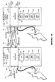
- FIG. 1A shows a prior art network system 10 such as might be used in the United States.
- System 10 includes a server 20 and a client/slave 30, each of which is mounted in a cabinet or relay-type rack 40.
- Rack 40 commonly measures perhaps 142 cm in height, and about 56 cm in width and depth.
- Source AC power to units 20 and 30 is received via a power cord 50 whose free end is connected to an AC connector 60 sized to fit into an AC wall outlet receptacle 70.
- the other end of power cord 50 is hardwired to an AC sequencer unit 80 within rack 40.
- source AC power is about 210 VAC to 240 VAC, 50 Hz to 60 Hz, 30 A maximum.
- Each unit 20, 30 includes an AC sequencer 80 that receives source AC via hardwired power cord 50, and sequentially provides AC operating power to other units within unit 20 or unit 30.
- unit 20 is a server unit 20, it will include a central processing unit card (“CPU") 90, which card is not present in slave unit 30.
- CPU central processing unit card
- present in unit 20 and slave unit 30 are a fan tray 100 for cooling the unit, and storage or memory trays, shown as 110A, 110B, 110C, etc.
- the storage units may include perhaps six hard disk drive assemblies, compact disk (“CD) assemblies, optical disk assemblies, and magnetic tape drives.
- Client/slave unit 40 is shown with a further memory unit, memory tray 110C, that has been plugged into cabinet 30 in lieu of a CPU card tray 80. In this fashion, unit 30 is able to provide additional storage capability by allowing three rather than two trays for memory assemblies.
- AC sequencer 80 a function of AC sequencer 80 is to receive raw AC power from wall socket 70, and to sequentially provide operating power to other units within the same rack 40.
- each AC sequencer 80 typically outputs AC and DC operating voltage to three power output ports.
- a first outlet port 120 provides the "unswitched” AC voltage as soon as operating voltage is coupled to the AC sequencer.
- a second outlet port 130 provides a "switched 1" AC voltage which is defined as a voltage which is applied only after application of a POWER-ON switch closure control signal to port 135-IN.
- a third outlet port 140 provides a "switched 2" AC voltage,which is defined as a voltage which is applied only after a delay time of about four to six seconds from occurrence of the "switched 1" AC power.
- each AC sequencer 80 and control input port 135-IN is hardwired to the AC sequencer. Further, each AC sequencer outputs control signals through an output control port 135-OUT. These control signals may be coupled via a cable 155 to the input control port 135-IN of another unit 30, as shown in Figure 1A.
- System 10 in Figure 1A is intended for use in the United States.
- wall connector 70, AC connector plug 60 and power cord 50 (among other components) must satisfy Underwriter Laboratories ("UL") standards that apply to electrical equipment used in the United States.
- UL Underwriter Laboratories
- the diameter and number of wires within the power cord 50 and the dimensions and configuration of the AC connector plug 60 will be governed by applicable UL standards.
- Figure 1B depicts a system 10' such as might be used in Europe or in another country whose electrical power standards do not conform to UL standards.
- wall-mounted AC outlet receptacle 70' will have a different configuration than a U.L. approved receptacle 70. Because applicable standards differ, AC plug 60', and AC power cord 50' will be different, and AC connector 60', and indeed sequencer 80' must thus be changed for system 10' from what was manufactured for system 10.
- Prior art AC sequencers such as shown in Figures 1A and 1B suffer an additional deficiency in that often there is a need for more resources than can be supported in a single cabinet rack 40.
- server 20 may require more storage capacity than can be accommodated using only memory trays 110A, 110B, yet there are no additional tray spaces to receive additional memory.
- One solution might be to daisy-chain server 20 with a slave 30 using cable 155 and associated connectors. This might provide server 20 with more resources, for example, three additional trays of memory within cabinet 30. In such an application, unit 30 would not be a client per se, but rather a slave that provides additional resources to master unit 20.
- daisy-chaining is not readily implemented using prior art AC sequencers because there is not a universally accepted connector for the control input/output signals 135-IN, 135-OUT.
- a second impediment to such daisy-chaining is that the control signals presented at 135-IN could only be switch openings or closures (e.g., a 0 ⁇ or ⁇ ⁇ condition). If the control could also accept voltage or current source signals, it would be possible to couple slave sequencers to master sequencers such that full control and status information with respect to the slave unit was available at the server unit.
- an AC sequencer to which AC operating power may be coupled in a universal fashion such that a common AC sequencer complies with applicable power standards in all major countries of the world.
- an AC sequencer should include a universally acceptable control input and output port that can respond not only to a switch closure, but to a voltage source signal as well as to a current source signal.
- an AC sequencer should also provide indication of the status of units in a slave system coupled to a master system AC sequencer.
- the present invention provides an AC sequencer with a universally accepted inlet connector, preferably a IEC 309 connector.
- An AC power cord and AC connector that comply with electrical standards in the country in which the sequencer is used provide AC power to the sequencer via a mating, internationally accepted, IEC 309-type connector.
- the AC power cord and AC connector requirements are governed by the electrical power standards of the country in which the server or client/slave containing the AC sequencer is used, the identical AC sequencer may be used in all countries.
- an AC sequencer provides universally accepted internal control signal input and output connectors, to couple control and status signals that may be from a voltage source, a current source, and/or switch openings/closures. This enables a server unit containing a master AC sequencer to receive status information as to peripheral equipment plugged into a slave unit that is daisy-chained to the master unit. Further, the slave unit may be powered-down from the master unit or from the slave unit.
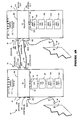
- FIGS 2A and 2B depict a system 10" in which server units 20 and slave units 30 each include an AC sequencer 200. Unless otherwise noted, elements in Figures 2A and 2B bearing similar numbers to elements shown in Figure 1A and 1B may be the same elements.
- AC sequencer 200 includes a preferably internationally accepted input power connector 202 (or J13) to receive operating source AC voltage.
- connector 202 meets applicable power standards and regulations in the major countries of the world.
- Connector 202 preferably is an IEC 309 connector, and is mounted on an accessible surface of AC sequencer 200.
- IEC 309-compatible connectors 202 will have a 30 A current capacity (UL and CAS rating), or 32 A current capacity (VDE/DEMKO/SEMKO rating).
- a "J-" nomenclature may be used to identify the connectors on the schematic of Figure 4.
- connector 202 is also referred to herein as connector J13.
- AC wall sockets 70, 70' are different, as are AC connector plugs 60, 60', and AC power cords 50, 50'. It is understood that these sockets, plugs, and power cords will and indeed must conform to electrical power standards and regulations applicable to the country in which system 10" is being used. But note that the other end of each power cord 50, 50' terminates in an identical connector 204 that plugs into or otherwise mates with AC sequencer-mounted connector 202. Thus, although power cords 50, 50' and AC connector plugs 60, 60' may vary widely from country to country, the same connector 202-equipped AC sequencer 200 may be sold and used in each such country. This is in stark contrast to prior art AC sequencers such as shown in Figures 1A and 1B, which essentially must be dedicated at time of manufacture for use in a given country or region.
- AC sequencer 200 includes a control-in connector 204, a status-input connector 206, a control-out connector 208, and a status-out connector 210.
- each of these connectors is mounted on an accessible surface of AC sequencer 200 and meets applicable electrical standards and regulations in all countries.
- a single configuration of AC sequencer 200 may be manufactured and sold for use in substantially all countries. Understandably, the ability to manufacture and sell a single model AC sequencer worldwide rather than having to produce different models for different countries represents a savings in manufacturing and warehousing.
- AC sequencer 200 also sequentially outputs unswitched, switched 1 and switched 2 AC at voltage output ports 120, 130 and 140, as was described with respect to prior art sequencers 80 and 80'.
- sequencer 200 Contributing the universal aspect of sequencer 200 is the ability to permit intelligent daisy-chaining between a master unit, e.g., in system 20 in Figure 2A or 2B, to one or more slave AC sequencers in other racks or cabinets, e.g., in system 30.
- intelligent daisy-chaining it is meant that the master sequencer in system 20 has full control and status information with respect to the sequencer and other units within the slave system 30.
- control signals from master unit 20 to slave unit 30 are provided via a control cable or bus 155 whose ends terminate with connectors 208X and 204X, which respectively mate or connect with AC sequencer-mounted connectors 208 and 204.
- status signals are carried by a status cable or bus 212 whose ends terminate with connectors 210X and 206X, which respectively mate or connect with AC sequencer-mounted connectors 210 and 206.
- the status-in port 206 of the master unit 20 is connected by a cable and connectors to the status-out port 208 of the slave unit 30.
- a visible surface of console or rack 40 is provided with control switches 214, including for example a three-way rocker switch S1, and with status indicators 216, which may include light-emitting diodes ("LEDs").
- Controls 214 and indicators 216 will be described more fully herein.
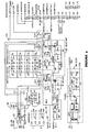
- FIG 3 is a block diagram of AC sequencer 200, a schematic for which appears as Figure 4.
- source AC operating potential is coupled to sequencer 200 via a universally accepted connector 202 (J13), mounted on the sequencer itself.
- sequencer 200 can receive input control signals at a control input connector 204 (CONTROL-IN), and can receive status signals at status input connector 206 (STATUS-IN).
- CONTROL-IN control input connector 204
- status input connector 206 STATUS-IN
- sequencer 200 can input and output control and status signals that are switch openings/closings, and/or current source signals, and/or voltage source signals. It is this flexibility in the nature of the AC sequencer control signals that permits the present invention to implement intelligent daisy-chaining.
- sequencer 200 sequentially provides unswitched AC at internal AC outlet port 120 (connectors J1, J2), switched 1 AC at internal AC outlet port 130 (connectors J5, J6, J7), and switched 2 AC at internal AC outlet port 140 (connectors J9, J10, J11, J12). Further, sequencer 20 provides control output signals at port connector 208 (CONTROL-OUT), and provides status output signals at port connector 210 (STATUS-OUT, J15-4,5).
- source AC is received at AC input port 202 (J13) and is filtered by line filter 220, and protected against current overload by a typically 30 A pair of circuit breakers 220.
- source AC is typically about 180-250 VAC, 50Hz-60Hz.
- the thus processed AC voltage is directly coupled to the first AC outlet port 120 (J1, J2), which receives AC power as soon as operating AC voltage is present at J13. Because no delay or other conditions are required to output this AC, AC present at 120" is referred to as "unswitched”.
- This unswitched AC preferably is output at two outlet connectors denoted J1 (an IEC 320-C19 connector) and J2 (an AMP Universal Mate-N-Lok 3-circuit connector).
- AC power from unswitched AC outlet port 120 typically is coupled to the CPU card cage 90.
- the AC sequencer is powered-up, filtered and current-protected AC voltage is delivered to the CPU, but not yet to any associated memory units.
- an AC-to-DC voltage regulator 240 outputs a regulated source of DC voltage (here, about +19.3 VDC) to various control and logic components 250.
- the logic circuitry enables a first relay RLY1, enabling it to output "switched 1" AC voltage to second AC outlet port 130.
- enablement occurs only after an input power-on command is received at the control input connector 204.
- a 4N37 optical isolator transducer permits remote switching control in response to a voltage-sourced or current-sourced control signal coupled to connector 204, or in response to a short-circuit presented across the connections present in connector 204.
- the input power-on command may be voltage and/or current sourced, and is not limited to a switch opening or closure as in the prior art.
- the second AC outlet port 130 is implemented with connectors denoted J5, J6, J7, J8 and preferably comprises AMP Universal Mate-N-Lok connector 3-circuit connectors.
- a light-emitting diode (“LED") LED1 coupled across the coil of RLY1 is used to visually signal status when RLY1 is energized and "switched 1" AC is being delivered at port 130.
- the "switched 1" AC voltage typically is coupled to storage units, e.g., 110A, 110B, 110C in Figures 2A, 2C, such as hard disks, CDs, optical disks, magnetic tape drives, among other peripheral devices mounted in rack 40 containing AC sequencer 200. In this fashion, it is ensured that CPU tray 90 receives operating potential before any of the memories trays are energized.
- the onset of AC power to AC input port J13 produces a pulsed DC signal from the control and logic circuitry 250.
- This DC pulse signal is coupled from the control and logic circuitry 250 as input to a delay circuit 260.
- Unit 260 delays this pulse by a fixed time period, typically about 4 to 6 seconds, and thereafter energizes a second relay RLY2 and, optionally, a third relay RLY3.
- Second relay RLY2 after the time delay, outputs "switched 2" AC voltage to third AC output port 140.
- This port is denoted J9, J10, J11, J12, and preferably comprises AMP Universal Mate-N-Lok connector 3-circuit connectors.
- An indicator LED2 provides visual status confirmation that RLY2 has energized and that "switched 2" voltage is present at connectors J9, J10, J11 and J12.
- "Switched 2" AC voltage may also be coupled to storage units in the rack containing AC sequencer 200. As shown in Figure 3, a fan tray 100 may be coupled to any of the "unswitched", “switched 1", or "switched 2" sources of AC.
- the third relay RLY3 is similarly energized after the time delay, and makes contact between "remote output" pins 4 and 5 on connecter J15, preferably a 9-circuit subminiature type "D" connector.
- the RLY3-switched connections may handle switch closures, voltage-sourced signals, and/or current-sourced signals.
- AC sequencer 200 preferably includes a three-way rocker-type control switch S1 that determines whether the sequencer is to be powered-up (e.g., turned-on), or is to be powered-up under local control, or under remote power-up control from another AC sequencer 200 in another rack or cabinet.
- S1 In the "OFF" position, S1 terminates AC input operating power from sequencer 200, even if source-AC is present at J13.
- S1 permits sequencer 200 to respond normally, e.g., to output AC voltages at output ports 120, 13", and 140.
- signals received at CONTROL-In port 204 (perhaps from a remote slave unit) can command a power-up state of sequencer 200.
- Intelligent daisy chain operation permit master unit 20 not only to utilize storage and other resources physically located in remote slave unit 30, but to sense operating conditions present in the remote unit and, if necessary, to power-off the remote unit.
- CPU tray 90 in master unit 20 can access five trays of memory storage (e.g., two storage units located in unit 20, and three additional storage trays located in unit 30).
- Control switches, e.g., 214, and status displays, e.g., 216 on rack 40 permit users of the master unit 20 to see and/or control what is occurring within the remote unit 30 (and vice versa, if desired).
- a system fan tray 100 is shown coupled to an AC sequencer 200 via mating connectors 270 (associate with the sequencer) and 270X, associated with the fan tray.
- fan tray 100 in the remote unit 30 fails, or that the air conditioning fails in the room in which remote unit 30 is located.
- Such failure(s) and resultant overheating can readily lead to degradation of data associated with any or all of the storage units located in the remote unit 30.
- remote unit 30 does not include a CPU tray, it is nonetheless coupled via connectors 270, 270X to its associated sequencer 200 in a slave unit 30, and via cables 155 and 212 to master unit 20. Because the signals carried by these cables can include voltage-sourced and current-sourced signals, at least one of the status signals can indicate a dangerous temperature condition within unit 30.
- CPU tray 90 within the master unit 20 can recognize this excess temperature condition and can issue a control signal via cable 155 that remotely powers-down, if necessary, unit 30 entirely, or any combination of "unswitched", “switched 1" and “switched 2" operating voltage. Thus, if the memory trays in remote unit 30 were operating from “switched 2" power, master unit 20 could remotely shutdown only the "switched 2" power within unit 30.
- a status indicator 216 at unit 20 could signal the excess temperature condition at unit 30, and can signal that unit 30 has been powered down by unit 20.
- This level of status recognition and control is simply not available with prior art AC sequencers.
- switch S1 in the AC sequencer in the remote unit 30 would be placed in the "REMOTE" position.
- a technician in the vicinity of the remote unit 30 who recognized the excess temperature condition could manually switch S1 to the"OFF" position, to power-down unit 30 (but not unit 20).
Abstract
Description
- The invention relates to AC sequencers that are used to power-up computer network servers, and more specifically to providing such sequencers that meet domestic and foreign power cord and connector specifications, and that can provide a daisy-chain function with status information as to another sequencer slaved to a first sequencer.
- Networks are electronic systems that include server stations that couple information to one or more client/slave stations. When a server is first turned on, e.g., when electrical power is first applied, it is important to first power server units such as the central processing system ("CPU"), often referred to as a "card cage", and then provide power to ancillary systems, including memory units. It is the function of an AC sequencer to ensure that server power-up applies power to server units in a correct sequence. For example, if power were simultaneously and instantly applied to all units within the server, the in-rush of current would almost certainly trip circuit breakers associated with the source of AC power into the sequencer.
- Figure 1A shows a prior
art network system 10 such as might be used in the United States.System 10 includes aserver 20 and a client/slave 30, each of which is mounted in a cabinet or relay-type rack 40.Rack 40 commonly measures perhaps 142 cm in height, and about 56 cm in width and depth. Source AC power tounits power cord 50 whose free end is connected to anAC connector 60 sized to fit into an ACwall outlet receptacle 70. As well be described, the other end ofpower cord 50 is hardwired to anAC sequencer unit 80 withinrack 40. Typically source AC power is about 210 VAC to 240 VAC, 50 Hz to 60 Hz, 30 A maximum. - Each
unit AC sequencer 80 that receives source AC viahardwired power cord 50, and sequentially provides AC operating power to other units withinunit 20 orunit 30. Becauseunit 20 is aserver unit 20, it will include a central processing unit card ("CPU") 90, which card is not present inslave unit 30. As shown in Figure 1A, present inunit 20 andslave unit 30 are afan tray 100 for cooling the unit, and storage or memory trays, shown as 110A, 110B, 110C, etc. The storage units may include perhaps six hard disk drive assemblies, compact disk ("CD) assemblies, optical disk assemblies, and magnetic tape drives. Client/slave unit 40 is shown with a further memory unit,memory tray 110C, that has been plugged intocabinet 30 in lieu of aCPU card tray 80. In this fashion,unit 30 is able to provide additional storage capability by allowing three rather than two trays for memory assemblies. - If AC operating power were simultaneously provided to
unit 20 andunit 30 at power-up, the resultant current surge could exceed the current limit of protective circuit breakers within each AC sequencer unit. Further, simultaneous receipt of AC operating power byCPU tray 90 and various associated memory trays, e.g., 110A, 110B, could result in inoperative starting states for themaster unit 20. Thus, a function ofAC sequencer 80 is to receive raw AC power fromwall socket 70, and to sequentially provide operating power to other units within thesame rack 40. - More specifically, each
AC sequencer 80 typically outputs AC and DC operating voltage to three power output ports. Afirst outlet port 120 provides the "unswitched" AC voltage as soon as operating voltage is coupled to the AC sequencer. Asecond outlet port 130 provides a "switched 1" AC voltage which is defined as a voltage which is applied only after application of a POWER-ON switch closure control signal to port 135-IN. Athird outlet port 140 provides a "switched 2" AC voltage,which is defined as a voltage which is applied only after a delay time of about four to six seconds from occurrence of the "switched 1" AC power. - The connection between each
AC sequencer 80 and control input port 135-IN is hardwired to the AC sequencer. Further, each AC sequencer outputs control signals through an output control port 135-OUT. These control signals may be coupled via acable 155 to the input control port 135-IN of anotherunit 30, as shown in Figure 1A. -
System 10 in Figure 1A is intended for use in the United States. As such,wall connector 70,AC connector plug 60 and power cord 50 (among other components) must satisfy Underwriter Laboratories ("UL") standards that apply to electrical equipment used in the United States. For example, the diameter and number of wires within thepower cord 50 and the dimensions and configuration of theAC connector plug 60 will be governed by applicable UL standards. - However, electrical power standards differ from country to country. Thus, although network systems, servers and client/slaves are commonly used world-wide, manufacturers of AC sequencers have had to manufacture different sequencer versions for different countries. For example, Figure 1B depicts a system 10' such as might be used in Europe or in another country whose electrical power standards do not conform to UL standards.
- Among other changes, wall-mounted AC outlet receptacle 70' will have a different configuration than a U.L. approved
receptacle 70. Because applicable standards differ, AC plug 60', and AC power cord 50' will be different, and AC connector 60', and indeed sequencer 80' must thus be changed for system 10' from what was manufactured forsystem 10. - Unfortunately, standards applicable in various foreign countries preclude providing AC sequencer 80' with multiple AC power cords 50' and AC connector 60'. Such standards also preclude providing differently shaped connectors on the AC sequencer, into one of which a suitable AC power cord could be plugged, rather than hard-wire the AC power cord to the AC sequencer. The other end of such an AC power cord could otherwise have attached an AC connector plug appropriate for the country in which the sequencer was to be used.
- The inability of prior
art AC sequencers 80, 80' to conform to applicable electrical power and connector standards in all major countries adds to the manufacturing cost that a "family" of sequencers must be produced. Stated differently, if a single AC sequencer could be designed for use world-wide, the cost to produce and indeed maintain the sequencer would be reduced. - Prior art AC sequencers such as shown in Figures 1A and 1B suffer an additional deficiency in that often there is a need for more resources than can be supported in a
single cabinet rack 40. For example,server 20 may require more storage capacity than can be accommodated usingonly memory trays chain server 20 with aslave 30 usingcable 155 and associated connectors. This might provideserver 20 with more resources, for example, three additional trays of memory withincabinet 30. In such an application,unit 30 would not be a client per se, but rather a slave that provides additional resources to masterunit 20. - Unfortunately, such daisy-chaining is not readily implemented using prior art AC sequencers because there is not a universally accepted connector for the control input/output signals 135-IN, 135-OUT. A second impediment to such daisy-chaining is that the control signals presented at 135-IN could only be switch openings or closures (e.g., a 0 Ω or ∞ Ω condition). If the control could also accept voltage or current source signals, it would be possible to couple slave sequencers to master sequencers such that full control and status information with respect to the slave unit was available at the server unit.
- Thus, there is a need for an AC sequencer to which AC operating power may be coupled in a universal fashion such that a common AC sequencer complies with applicable power standards in all major countries of the world. Further, such an AC sequencer should include a universally acceptable control input and output port that can respond not only to a switch closure, but to a voltage source signal as well as to a current source signal. Finally, such an AC sequencer should also provide indication of the status of units in a slave system coupled to a master system AC sequencer.
- The present invention provides an AC sequencer with a universally accepted inlet connector, preferably a IEC 309 connector. An AC power cord and AC connector that comply with electrical standards in the country in which the sequencer is used provide AC power to the sequencer via a mating, internationally accepted, IEC 309-type connector. Although the AC power cord and AC connector requirements are governed by the electrical power standards of the country in which the server or client/slave containing the AC sequencer is used, the identical AC sequencer may be used in all countries.
- Further, an AC sequencer according to the present invention provides universally accepted internal control signal input and output connectors, to couple control and status signals that may be from a voltage source, a current source, and/or switch openings/closures. This enables a server unit containing a master AC sequencer to receive status information as to peripheral equipment plugged into a slave unit that is daisy-chained to the master unit. Further, the slave unit may be powered-down from the master unit or from the slave unit.
- Examples of the invention will be described in conjunction with the accompanying drawings.
-
- FIGURE 1A depicts a system employing an AC sequencer manufactured according to applicable United States standards, according to the prior art;
- FIGURE 1B depicts a system employing an AC sequencer manufactured according to applicable foreign standards, according to the prior art;
- FIGURE 2A depicts a system employing an AC sequencer used in the United States, embodying the present invention;
- FIGURE 2B depicts a system employing the AC sequencer of Figure 2A in a foreign country, embodying the present invention;
- FIGURE 3 is a block diagram of an AC sequencer, embodying to the present invention;
- FIGURE 4 is a schematic of a preferred embodiment of the AC sequencer of Figure 3.
- Figures 2A and 2B depict a
system 10" in whichserver units 20 andslave units 30 each include anAC sequencer 200. Unless otherwise noted, elements in Figures 2A and 2B bearing similar numbers to elements shown in Figure 1A and 1B may be the same elements. - It is first seen that
AC sequencer 200 includes a preferably internationally accepted input power connector 202 (or J13) to receive operating source AC voltage. By internationally accepted, it is meant thatconnector 202 meets applicable power standards and regulations in the major countries of the world.Connector 202 preferably is anIEC 309 connector, and is mounted on an accessible surface ofAC sequencer 200. In practice IEC 309-compatible connectors 202 will have a 30 A current capacity (UL and CAS rating), or 32 A current capacity (VDE/DEMKO/SEMKO rating). In referring to this and other connectors herein, a "J-" nomenclature may be used to identify the connectors on the schematic of Figure 4. Thus,connector 202 is also referred to herein as connector J13. - Note in Figures 2A and 2B, that
AC wall sockets 70, 70' are different, as are AC connector plugs 60, 60', andAC power cords 50, 50'. It is understood that these sockets, plugs, and power cords will and indeed must conform to electrical power standards and regulations applicable to the country in whichsystem 10" is being used. But note that the other end of eachpower cord 50, 50' terminates in anidentical connector 204 that plugs into or otherwise mates with AC sequencer-mountedconnector 202. Thus, althoughpower cords 50, 50' and AC connector plugs 60, 60' may vary widely from country to country, the same connector 202-equippedAC sequencer 200 may be sold and used in each such country. This is in stark contrast to prior art AC sequencers such as shown in Figures 1A and 1B, which essentially must be dedicated at time of manufacture for use in a given country or region. - Referring still to Figures 2A and 2B,
AC sequencer 200 includes a control-inconnector 204, a status-input connector 206, a control-outconnector 208, and a status-outconnector 210. Preferably each of these connectors is mounted on an accessible surface ofAC sequencer 200 and meets applicable electrical standards and regulations in all countries. As such, a single configuration ofAC sequencer 200 may be manufactured and sold for use in substantially all countries. Understandably, the ability to manufacture and sell a single model AC sequencer worldwide rather than having to produce different models for different countries represents a savings in manufacturing and warehousing. - Of course
AC sequencer 200 also sequentially outputs unswitched, switched 1 and switched 2 AC atvoltage output ports prior art sequencers 80 and 80'. - Contributing the universal aspect of
sequencer 200 is the ability to permit intelligent daisy-chaining between a master unit, e.g., insystem 20 in Figure 2A or 2B, to one or more slave AC sequencers in other racks or cabinets, e.g., insystem 30. By intelligent daisy-chaining it is meant that the master sequencer insystem 20 has full control and status information with respect to the sequencer and other units within theslave system 30. - Thus, in Figures 2A and 2B, within
system 10", control signals frommaster unit 20 toslave unit 30 are provided via a control cable orbus 155 whose ends terminate with connectors 208X and 204X, which respectively mate or connect with AC sequencer-mountedconnectors bus 212 whose ends terminate withconnectors connectors port 206 of themaster unit 20 is connected by a cable and connectors to the status-outport 208 of theslave unit 30. - A visible surface of console or
rack 40 is provided withcontrol switches 214, including for example a three-way rocker switch S1, and withstatus indicators 216, which may include light-emitting diodes ("LEDs").Controls 214 andindicators 216 will be described more fully herein. - Figure 3 is a block diagram of
AC sequencer 200, a schematic for which appears as Figure 4. As noted, source AC operating potential is coupled tosequencer 200 via a universally accepted connector 202 (J13), mounted on the sequencer itself. In addition to receiving source AC atconnector 202,sequencer 200 can receive input control signals at a control input connector 204 (CONTROL-IN), and can receive status signals at status input connector 206 (STATUS-IN). In contrast to prior art sequencers such as shown in Figures 1A and 1B,sequencer 200 can input and output control and status signals that are switch openings/closings, and/or current source signals, and/or voltage source signals. It is this flexibility in the nature of the AC sequencer control signals that permits the present invention to implement intelligent daisy-chaining. - As noted,
sequencer 200 sequentially provides unswitched AC at internal AC outlet port 120 (connectors J1, J2), switched 1 AC at internal AC outlet port 130 (connectors J5, J6, J7), and switched 2 AC at internal AC outlet port 140 (connectors J9, J10, J11, J12). Further,sequencer 20 provides control output signals at port connector 208 (CONTROL-OUT), and provides status output signals at port connector 210 (STATUS-OUT, J15-4,5). - As shown in Figure 3 and Figure 4, source AC is received at AC input port 202 (J13) and is filtered by
line filter 220, and protected against current overload by a typically 30 A pair ofcircuit breakers 220. In the embodiment shown, source AC is typically about 180-250 VAC, 50Hz-60Hz. - The thus processed AC voltage is directly coupled to the first AC outlet port 120 (J1, J2), which receives AC power as soon as operating AC voltage is present at J13. Because no delay or other conditions are required to output this AC, AC present at 120" is referred to as "unswitched". This unswitched AC preferably is output at two outlet connectors denoted J1 (an IEC 320-C19 connector) and J2 (an AMP Universal Mate-N-Lok 3-circuit connector).
- With reference to Figures 2A, 2B, 3 and 4, internal to rack 40 containing
sequencer 200, AC power from unswitchedAC outlet port 120 typically is coupled to theCPU card cage 90. Thus, as soon as the AC sequencer is powered-up, filtered and current-protected AC voltage is delivered to the CPU, but not yet to any associated memory units. - As shown in Figure 3 and Figure 4, an AC-to-
DC voltage regulator 240 outputs a regulated source of DC voltage (here, about +19.3 VDC) to various control andlogic components 250. The logic circuitry enables a first relay RLY1, enabling it to output "switched 1" AC voltage to secondAC outlet port 130. However, enablement occurs only after an input power-on command is received at thecontrol input connector 204. In the embodiment of Figure 4, a 4N37 optical isolator transducer permits remote switching control in response to a voltage-sourced or current-sourced control signal coupled toconnector 204, or in response to a short-circuit presented across the connections present inconnector 204. Thus, the input power-on command may be voltage and/or current sourced, and is not limited to a switch opening or closure as in the prior art. - The second
AC outlet port 130 is implemented with connectors denoted J5, J6, J7, J8 and preferably comprises AMP Universal Mate-N-Lok connector 3-circuit connectors. Preferably a light-emitting diode ("LED") LED1 coupled across the coil of RLY1 is used to visually signal status when RLY1 is energized and "switched 1" AC is being delivered atport 130. The "switched 1" AC voltage typically is coupled to storage units, e.g., 110A, 110B, 110C in Figures 2A, 2C, such as hard disks, CDs, optical disks, magnetic tape drives, among other peripheral devices mounted inrack 40 containingAC sequencer 200. In this fashion, it is ensured thatCPU tray 90 receives operating potential before any of the memories trays are energized. - As shown in Figures 3 and 4, the onset of AC power to AC input port J13 produces a pulsed DC signal from the control and
logic circuitry 250. This DC pulse signal is coupled from the control andlogic circuitry 250 as input to adelay circuit 260.Unit 260 delays this pulse by a fixed time period, typically about 4 to 6 seconds, and thereafter energizes a second relay RLY2 and, optionally, a third relay RLY3. - Second relay RLY2, after the time delay, outputs "switched 2" AC voltage to third
AC output port 140. This port is denoted J9, J10, J11, J12, and preferably comprises AMP Universal Mate-N-Lok connector 3-circuit connectors. An indicator LED2 provides visual status confirmation that RLY2 has energized and that "switched 2" voltage is present at connectors J9, J10, J11 and J12. "Switched 2" AC voltage may also be coupled to storage units in the rack containingAC sequencer 200. As shown in Figure 3, afan tray 100 may be coupled to any of the "unswitched", "switched 1", or "switched 2" sources of AC. - The third relay RLY3 is similarly energized after the time delay, and makes contact between "remote output" pins 4 and 5 on connecter J15, preferably a 9-circuit subminiature type "D" connector. The RLY3-switched connections may handle switch closures, voltage-sourced signals, and/or current-sourced signals.
-
AC sequencer 200 preferably includes a three-way rocker-type control switch S1 that determines whether the sequencer is to be powered-up (e.g., turned-on), or is to be powered-up under local control, or under remote power-up control from anotherAC sequencer 200 in another rack or cabinet. In the "OFF" position, S1 terminates AC input operating power fromsequencer 200, even if source-AC is present at J13. In the "LOCAL" position, S1 permits sequencer 200 to respond normally, e.g., to output AC voltages atoutput ports 120, 13", and 140. In the "REMOTE" position, signals received at CONTROL-In port 204 (perhaps from a remote slave unit) can command a power-up state ofsequencer 200. - Intelligent daisy chain operation, such as shown in Figures 2A and 2B,
permit master unit 20 not only to utilize storage and other resources physically located inremote slave unit 30, but to sense operating conditions present in the remote unit and, if necessary, to power-off the remote unit. - In Figure 2A, for example,
CPU tray 90 inmaster unit 20 can access five trays of memory storage (e.g., two storage units located inunit 20, and three additional storage trays located in unit 30). Control switches, e.g., 214, and status displays, e.g., 216 onrack 40 permit users of themaster unit 20 to see and/or control what is occurring within the remote unit 30 (and vice versa, if desired). - In Figure 3, a
system fan tray 100 is shown coupled to anAC sequencer 200 via mating connectors 270 (associate with the sequencer) and 270X, associated with the fan tray. Suppose, for example, thatfan tray 100 in theremote unit 30 fails, or that the air conditioning fails in the room in whichremote unit 30 is located. Such failure(s) and resultant overheating can readily lead to degradation of data associated with any or all of the storage units located in theremote unit 30. Althoughremote unit 30 does not include a CPU tray, it is nonetheless coupled viaconnectors sequencer 200 in aslave unit 30, and viacables master unit 20. Because the signals carried by these cables can include voltage-sourced and current-sourced signals, at least one of the status signals can indicate a dangerous temperature condition withinunit 30. -
CPU tray 90 within themaster unit 20 can recognize this excess temperature condition and can issue a control signal viacable 155 that remotely powers-down, if necessary,unit 30 entirely, or any combination of "unswitched", "switched 1" and "switched 2" operating voltage. Thus, if the memory trays inremote unit 30 were operating from "switched 2" power,master unit 20 could remotely shutdown only the "switched 2" power withinunit 30. - In addition, if desired a
status indicator 216 atunit 20 could signal the excess temperature condition atunit 30, and can signal thatunit 30 has been powered down byunit 20. This level of status recognition and control is simply not available with prior art AC sequencers. To benefit from such remote status recognition and control, switch S1 in the AC sequencer in theremote unit 30 would be placed in the "REMOTE" position. Of course, a technician in the vicinity of theremote unit 30 who recognized the excess temperature condition could manually switch S1 to the"OFF" position, to power-down unit 30 (but not unit 20). - It will be appreciate that because the status and control signals are coupled to
cable 155 by internationally acceptable connectors at 135-OUT and 135-IN, a single model ofAC sequencer 200 may be used in essentially all countries.
Claims (15)
- An alternating current (AC) sequencer coupleable to a source of AC input operating voltage from which at least two output modes of AC operating voltage are sequentially provided by said AC sequencer, comprising:a source AC input connector, mounted to said AC sequencer, that receives said AC input operating voltage and provides said AC input operating voltage to said AC sequencer;wherein a source of said AC input operating voltage is coupled to said AC sequencer by a second connector that attaches to said source AC input connector;a first AC outlet port that is coupled to said connector to provide a first unswitched output AC operating voltage whenever said AC input operating voltage is present at said connector;an input control port coupled to an input control port connector; anda circuit, coupled to said connector and to said input control port, that outputs at least one of (i) a switched 1 version of said AC input operating voltage but only when a power-on control signal is coupled to said input control port connector, and (ii) a switched 2 version of said switched 1 version of said AC input operating voltage but only after a delay time of at least one second from occurrence of said switched 1 version.
- The AC sequencer of claim 1, wherein:
said source AC input connector is an internationally accepted input power connector. - The AC sequencer of claim 1, wherein said delay time ranges from about four to six seconds and is created by said circuit.
- The AC sequencer of claim 1, further including:a status input port coupled to a status input port connector and to said circuit;an output control port coupled to an output control connector and to said circuit;an output status port coupled to an output status connector and to said circuit; andat least one indicator signalling status associated with a signal presented to said status input port connector;wherein status of a second said AC sequencer may be sensed by said circuit in said AC sequencer by coupling together a said output status connector on said second AC sequencer to said status input port connector of said AC sequencer; andwherein said status of said second AC sequencer may be signalled by a said indicator on said AC sequencer.
- The AC sequencer of claim 4, wherein said circuit further includes at least one transducer element permitting said circuit to respond to a signal at said status input port connector that is selected from the group consisting of (i) a switch opening, (ii) a switch closure, (iii) a voltage-based signal, and (iv) a current-based signal.
- The AC sequencer of claim 4, wherein said circuit further includes at least one transducer element permitting said circuit to respond to a signal at said control input port connector that is selected from the group consisting of (i) a switch opening, (ii) a switch closure, (iii) a voltage-based signal, and (iv) a current-based signal;
wherein said second AC sequencer may be remotely controlled by said circuit in said AC sequencer in at least one mode selected from the group consisting of (i) said second AC sequencer is caused to receive said source AC input operating voltage and to power-on, (ii) said second AC sequencer is caused to not receive said source AC input operating voltage and to power-off, (iii) said second AC sequencer is caused to cease outputting a said switched 2 version of said AC input operating voltage, and (iv) said second AC sequencer is caused to cease outputting a said switched 1 version of said AC input operating voltage. - The AC sequencer of claim 1, wherein:
said circuit includes a first transducer permitting said circuit to respond to a signal at said control input port connector that is selected from the group consisting of (i) a switch opening, (ii) a switch closure, (iii) a voltage-based signal, and (iv) a current-based signal;
and further including:a status input port coupled to a status input port connector and to a second transducer in said circuit permitting said circuit to respond to a signal at said status input port connector that is selected from the group consisting of (i) a switch opening, (ii) a switch closure, (iii) a voltage-based signal, and (iv) a current-based signal;an output control port coupled to an output control connector and to said circuit;an output status port coupled to an output status connector and to said circuit; andan indicator signalling status associated with a signal presented to said status input port connector. - For use with an electronic system having a master system that includes a first subsystem and a second subsystem that must receive AC operating power after AC operating power is applied to said first subsystem, said electron system having a slave system that includes a first slave subsystem and a second slave subsystem that must receive AC operating power after AC operating power is applied to said first slave subsystem, a master AC sequencer sequentially providing AC operating power to said master system and a slave AC sequencer sequentially providing AC operating power to said slave system, each said AC sequencer being identical and comprising:a source AC input connector, mounted to said AC sequencer, that if coupled by a mating connector to a source of AC input operating voltage receives said AC input operating voltage and provides said AC input operating voltage to said AC sequencer;a first AC outlet port that is coupled to said connector to provide a first unswitched output AC operating voltage whenever said AC input operating voltage is present at said connector, said first AC outlet port being coupled to said first subsystem;a circuit, coupled to said connector and to said input control port, that outputs at least one of (i) a switched 1 version of said AC input operating voltage but only when a power-on control signal is coupled to said input control port connector, and (ii) a switched 2 version of said switched 1 version of said AC input operating voltage but only after a delay time of at least one second from occurrence of said switched 1 version;said second subsystem receiving from said circuit one of said switched 1 and said switched 2 version of said AC input operating voltage;an input control port coupled to an input control port connector and to said circuit;a status input port coupled to a status input port connector and to said circuit;an output control port coupled to an output control connector and to said circuit; andan output status port coupled to an output status connector and to said circuit;said circuit being responsive to a signal present at said input control port connector, at said status input port, or a combination thereof, to be selected from the group consisting of (i) a switch opening, (ii) a switch closure, (iii) a voltage-based signal, and (iv) a current-based signal.
- The AC sequencer of claim 8, wherein said source AC input connector is an internationally accepted input power connector.
- The AC sequencer of claim 8, wherein:said master system is a server in which said first subsystem includes a central processing unit and in which said second subsystem include a memory unit; andwherein said slave unit is a client in which said first slave subsystem includes a memory unit, and in which said second subsystem includes a fan unit.
- The AC sequencer of claim 10, wherein said status output port of said slave system is coupled to said status input port of said master system, and wherein said control output port of said master system is coupled to said control input port of said slave system;
wherein said slave AC sequencer may be remotely controlled by said circuit in said master AC sequencer in at least one mode selected from the group consisting of (i) said slave AC sequencer is caused to receive said source AC input operating voltage and to power-on, (ii) said slave AC sequencer is caused to not receive said source AC input operating voltage and to power-off, (iii) said slave AC sequencer is caused to cease outputting a said switched 2 version of said AC input operating voltage, and (iv) said slave AC sequencer is caused to cease outputting a said switched 1 version of said AC input operating voltage. - The AC sequencer of claim 10, further includingat least one indicator signalling status associated with a signal presented to said status input port connector;wherein a said status indicator disposed adjacent said master system provides status information of conditions present within said slave system.
- The AC sequencer of claim 12, wherein:
said status information includes at least one information selected from the group consisting of (i) status of said memory unit in said slave unit, and (ii) operating condition of said fan unit in said slave unit. - A method permitting an AC sequencer to universally and sequentially provide AC operating voltage from a source of AC input operating voltage, the method including the following steps:(a) mounting a source AC input connector to said AC sequencer, said source AC input connector receiving said AC input operating voltage and providing said AC input operating voltage to said AC sequencer;(b) coupling a source of said AC input operating voltage to said AC sequencer by a second connector that attaches to said source AC input connector;(c) providing said AC sequencer with a first AC outlet port that is coupled to said connector to provide a first unswitched output AC operating voltage whenever said AC input operating voltage is present at said AC input connector;(c) providing an input control port coupled to an input control port connector on said AC sequencer; and(d) providing circuitry, coupled to said connector and to said input control port, that outputs at least one of (i) a switched 1 version of said AC input operating voltage but only when a power-on control signal is coupled to said input control port connector, and (ii) a switched 2 version of said switched 1 version of said AC input operating voltage but only after a delay time of at least one second from occurrence of said switched 1 version.
- The method of claim 14, wherein at step (a), said source AC input connector is an internationally accepted input power connector.
Applications Claiming Priority (2)
| Application Number | Priority Date | Filing Date | Title |
|---|---|---|---|
| US621827 | 1996-03-22 | ||
| US08/621,827 US5644174A (en) | 1996-03-22 | 1996-03-22 | Universal AC sequencer for a server |
Publications (2)
| Publication Number | Publication Date |
|---|---|
| EP0797138A2 true EP0797138A2 (en) | 1997-09-24 |
| EP0797138A3 EP0797138A3 (en) | 1998-05-06 |
Family
ID=24491803
Family Applications (1)
| Application Number | Title | Priority Date | Filing Date |
|---|---|---|---|
| EP97301996A Withdrawn EP0797138A3 (en) | 1996-03-22 | 1997-03-24 | Universal ac sequencer for a server |
Country Status (3)
| Country | Link |
|---|---|
| US (2) | US5644174A (en) |
| EP (1) | EP0797138A3 (en) |
| JP (1) | JPH10105289A (en) |
Families Citing this family (14)
| Publication number | Priority date | Publication date | Assignee | Title |
|---|---|---|---|---|
| US5955791A (en) * | 1997-04-14 | 1999-09-21 | Irlander; James E. | Master/slave circuit for dust collector |
| US20020057206A1 (en) * | 1999-05-11 | 2002-05-16 | Charles H. Reynolds | Method and appparatus for an improved remotely switchable power supply |
| US8181043B1 (en) | 1999-05-11 | 2012-05-15 | Cyber Switching, Inc. | Methods and apparatus for improved remotely switchable power supply |
| US6766222B1 (en) * | 2000-06-14 | 2004-07-20 | Advanced Micro Devices, Inc. | Power sequencer control circuit |
| US6882530B2 (en) * | 2003-03-31 | 2005-04-19 | Sun Microsystems, Inc. | Integrated component rack and AC power distribution |
| WO2005043362A2 (en) * | 2003-10-30 | 2005-05-12 | International Power Switch | Power switch |
| GB2427513B (en) * | 2005-06-21 | 2007-08-01 | Peter Robertson | An improved sensing socket assembly |
| WO2008057386A2 (en) * | 2006-11-01 | 2008-05-15 | Carling Technologies, Inc. | Remote power management and monitoring system for solid state circuit breaker control with manual bypass |
| US7479714B1 (en) * | 2006-11-13 | 2009-01-20 | Sprint Communications Company L.P. | Apparatus and method for multiple-module electronic system power control |
| JP5020156B2 (en) * | 2008-04-25 | 2012-09-05 | 株式会社タイトー | Power-saving module device for game machines |
| WO2009135250A1 (en) * | 2008-05-05 | 2009-11-12 | Tricklestar Ltd | In-line power controller |
| WO2010019137A1 (en) * | 2008-08-12 | 2010-02-18 | Hewlett-Packard Development Company, L.P. | Power conserving ac power outlet on a computer |
| JP5083290B2 (en) * | 2009-10-23 | 2012-11-28 | 富士通株式会社 | Storage system |
| WO2015173369A1 (en) * | 2014-05-14 | 2015-11-19 | Barco Nv | Energy efficient power sequencer control circuit |
Citations (3)
| Publication number | Priority date | Publication date | Assignee | Title |
|---|---|---|---|---|
| DE9304011U1 (en) * | 1993-03-18 | 1993-07-15 | Reiter, Hubert, 8011 Hohenbrunn, De | |
| US5384490A (en) * | 1992-06-15 | 1995-01-24 | Unisys Corporation | Universal power distribution system |
| US5450334A (en) * | 1993-11-01 | 1995-09-12 | Pulizzi Engineering, Inc. | One time programmable switched-output controller |
Family Cites Families (5)
| Publication number | Priority date | Publication date | Assignee | Title |
|---|---|---|---|---|
| US4593349A (en) * | 1982-07-22 | 1986-06-03 | Honeywell Information Systems Inc. | Power sequencer |
| US5081609A (en) * | 1989-01-10 | 1992-01-14 | Bull Hn Information Systems Inc. | Multiprocessor controller having time shared control store |
| US5375209A (en) * | 1992-03-27 | 1994-12-20 | Cyrix Corporation | Microprocessor for selectively configuring pinout by activating tri-state device to disable internal clock from external pin |
| US5490254A (en) * | 1992-11-04 | 1996-02-06 | United Technologies Corporation | MIL-STD-1553 interface device having autonomous operation in all modes |
| US5563455A (en) * | 1995-02-27 | 1996-10-08 | Sun Microsystems, Inc. | Method and apparatus for sequencing and controlling power distribution |
-
1996
- 1996-03-22 US US08/621,827 patent/US5644174A/en not_active Ceased
-
1997
- 1997-03-24 JP JP9110022A patent/JPH10105289A/en active Pending
- 1997-03-24 EP EP97301996A patent/EP0797138A3/en not_active Withdrawn
-
2001
- 2001-07-26 US US09/916,497 patent/USRE38004E1/en not_active Expired - Fee Related
Patent Citations (3)
| Publication number | Priority date | Publication date | Assignee | Title |
|---|---|---|---|---|
| US5384490A (en) * | 1992-06-15 | 1995-01-24 | Unisys Corporation | Universal power distribution system |
| DE9304011U1 (en) * | 1993-03-18 | 1993-07-15 | Reiter, Hubert, 8011 Hohenbrunn, De | |
| US5450334A (en) * | 1993-11-01 | 1995-09-12 | Pulizzi Engineering, Inc. | One time programmable switched-output controller |
Non-Patent Citations (2)
| Title |
|---|
| "REMOTE POWER OUTLET DEVICE" IBM TECHNICAL DISCLOSURE BULLETIN, vol. 32, no. 10B, 1 March 1990, page 341/342 XP000097908 * |
| EDELSON R H: "MULTIPLE TIME-DELAYED SEQUENCED SWITCHING METHOD MEETS DEMANDS" COMPUTER TECHNOLOGY REVIEW, vol. 8, no. 6, 1 January 1988, pages 110-113, XP000260754 * |
Also Published As
| Publication number | Publication date |
|---|---|
| EP0797138A3 (en) | 1998-05-06 |
| JPH10105289A (en) | 1998-04-24 |
| US5644174A (en) | 1997-07-01 |
| USRE38004E1 (en) | 2003-02-25 |
Similar Documents
| Publication | Publication Date | Title |
|---|---|---|
| US5644174A (en) | Universal AC sequencer for a server | |
| US6744150B2 (en) | Outlet strip controlled by PC using low voltage powertap | |
| US6201319B1 (en) | Uninterruptible power supply | |
| KR101503109B1 (en) | Multi-capacity power supply for electronic devices | |
| US20210013735A1 (en) | Intelligent automatic transfer switch module | |
| US6445088B1 (en) | Multipurpose data port | |
| US6586849B2 (en) | Electrical power strip for use with a computer and associated peripheral devices | |
| US8185333B2 (en) | Automated load assessment device and method | |
| EP0757351A2 (en) | Computer frame structure with modular housings | |
| GB2386004A (en) | Socket assembly | |
| EP2624375B1 (en) | Power distribution system | |
| WO2001018939A2 (en) | Method and apparatus for delivering uninterrupted power | |
| US20050073199A1 (en) | Swithcing assembly and method | |
| Cisco | Chapter 2 Installing the SN 5420 Storage Router | |
| Cisco | Maintaining the AS5800 Access Server | |
| EP0757321A1 (en) | I/O bus in a multiple drive library computer system | |
| Cisco | Maintaining the AS5800 Access Server | |
| Cisco | Enclosure and Card Installation | |
| US10965149B2 (en) | Electrical power restoration system for a circuit assembly and method | |
| JP3138210B2 (en) | LAN concentrator | |
| US11326770B2 (en) | Under cabinet light interface device and lighting device interface device | |
| CN210468885U (en) | Composite power supply switching device | |
| WO2003007449A1 (en) | Switching assembly and method | |
| AU2002344684A1 (en) | Switching assembly and method | |
| AU5590101A (en) | Switching assembly |
Legal Events
| Date | Code | Title | Description |
|---|---|---|---|
| PUAI | Public reference made under article 153(3) epc to a published international application that has entered the european phase |
Free format text: ORIGINAL CODE: 0009012 |
|
| AK | Designated contracting states |
Kind code of ref document: A2 Designated state(s): DE FR GB IT NL SE |
|
| PUAL | Search report despatched |
Free format text: ORIGINAL CODE: 0009013 |
|
| AK | Designated contracting states |
Kind code of ref document: A3 Designated state(s): DE FR GB IT NL SE |
|
| 17P | Request for examination filed |
Effective date: 19981030 |
|
| 17Q | First examination report despatched |
Effective date: 20020417 |
|
| STAA | Information on the status of an ep patent application or granted ep patent |
Free format text: STATUS: THE APPLICATION IS DEEMED TO BE WITHDRAWN |
|
| 18D | Application deemed to be withdrawn |
Effective date: 20040330 |