EP0797265A2 - Gasdiffusionselektrode für Membranbrennstoffzellen und Verfahren zu ihrer Herstellung - Google Patents
Gasdiffusionselektrode für Membranbrennstoffzellen und Verfahren zu ihrer Herstellung Download PDFInfo
- Publication number
- EP0797265A2 EP0797265A2 EP97104134A EP97104134A EP0797265A2 EP 0797265 A2 EP0797265 A2 EP 0797265A2 EP 97104134 A EP97104134 A EP 97104134A EP 97104134 A EP97104134 A EP 97104134A EP 0797265 A2 EP0797265 A2 EP 0797265A2
- Authority
- EP
- European Patent Office
- Prior art keywords
- electrode
- membrane
- coating
- pore former
- gas diffusion
- Prior art date
- Legal status (The legal status is an assumption and is not a legal conclusion. Google has not performed a legal analysis and makes no representation as to the accuracy of the status listed.)
- Granted
Links
Images


Classifications
-
- H—ELECTRICITY
- H01—ELECTRIC ELEMENTS
- H01M—PROCESSES OR MEANS, e.g. BATTERIES, FOR THE DIRECT CONVERSION OF CHEMICAL ENERGY INTO ELECTRICAL ENERGY
- H01M4/00—Electrodes
- H01M4/86—Inert electrodes with catalytic activity, e.g. for fuel cells
- H01M4/90—Selection of catalytic material
- H01M4/92—Metals of platinum group
- H01M4/928—Unsupported catalytic particles; loose particulate catalytic materials, e.g. in fluidised state
-
- H—ELECTRICITY
- H01—ELECTRIC ELEMENTS
- H01M—PROCESSES OR MEANS, e.g. BATTERIES, FOR THE DIRECT CONVERSION OF CHEMICAL ENERGY INTO ELECTRICAL ENERGY
- H01M4/00—Electrodes
- H01M4/86—Inert electrodes with catalytic activity, e.g. for fuel cells
-
- H—ELECTRICITY
- H01—ELECTRIC ELEMENTS
- H01M—PROCESSES OR MEANS, e.g. BATTERIES, FOR THE DIRECT CONVERSION OF CHEMICAL ENERGY INTO ELECTRICAL ENERGY
- H01M4/00—Electrodes
- H01M4/86—Inert electrodes with catalytic activity, e.g. for fuel cells
- H01M4/90—Selection of catalytic material
- H01M4/92—Metals of platinum group
- H01M4/925—Metals of platinum group supported on carriers, e.g. powder carriers
- H01M4/926—Metals of platinum group supported on carriers, e.g. powder carriers on carbon or graphite
-
- H—ELECTRICITY
- H01—ELECTRIC ELEMENTS
- H01M—PROCESSES OR MEANS, e.g. BATTERIES, FOR THE DIRECT CONVERSION OF CHEMICAL ENERGY INTO ELECTRICAL ENERGY
- H01M8/00—Fuel cells; Manufacture thereof
- H01M8/10—Fuel cells with solid electrolytes
- H01M8/1004—Fuel cells with solid electrolytes characterised by membrane-electrode assemblies [MEA]
-
- H—ELECTRICITY
- H01—ELECTRIC ELEMENTS
- H01M—PROCESSES OR MEANS, e.g. BATTERIES, FOR THE DIRECT CONVERSION OF CHEMICAL ENERGY INTO ELECTRICAL ENERGY
- H01M2300/00—Electrolytes
- H01M2300/0017—Non-aqueous electrolytes
- H01M2300/0065—Solid electrolytes
- H01M2300/0082—Organic polymers
-
- H—ELECTRICITY
- H01—ELECTRIC ELEMENTS
- H01M—PROCESSES OR MEANS, e.g. BATTERIES, FOR THE DIRECT CONVERSION OF CHEMICAL ENERGY INTO ELECTRICAL ENERGY
- H01M4/00—Electrodes
- H01M4/86—Inert electrodes with catalytic activity, e.g. for fuel cells
- H01M4/90—Selection of catalytic material
- H01M4/92—Metals of platinum group
- H01M4/921—Alloys or mixtures with metallic elements
-
- Y—GENERAL TAGGING OF NEW TECHNOLOGICAL DEVELOPMENTS; GENERAL TAGGING OF CROSS-SECTIONAL TECHNOLOGIES SPANNING OVER SEVERAL SECTIONS OF THE IPC; TECHNICAL SUBJECTS COVERED BY FORMER USPC CROSS-REFERENCE ART COLLECTIONS [XRACs] AND DIGESTS
- Y02—TECHNOLOGIES OR APPLICATIONS FOR MITIGATION OR ADAPTATION AGAINST CLIMATE CHANGE
- Y02E—REDUCTION OF GREENHOUSE GAS [GHG] EMISSIONS, RELATED TO ENERGY GENERATION, TRANSMISSION OR DISTRIBUTION
- Y02E60/00—Enabling technologies; Technologies with a potential or indirect contribution to GHG emissions mitigation
- Y02E60/30—Hydrogen technology
- Y02E60/50—Fuel cells
-
- Y—GENERAL TAGGING OF NEW TECHNOLOGICAL DEVELOPMENTS; GENERAL TAGGING OF CROSS-SECTIONAL TECHNOLOGIES SPANNING OVER SEVERAL SECTIONS OF THE IPC; TECHNICAL SUBJECTS COVERED BY FORMER USPC CROSS-REFERENCE ART COLLECTIONS [XRACs] AND DIGESTS
- Y02—TECHNOLOGIES OR APPLICATIONS FOR MITIGATION OR ADAPTATION AGAINST CLIMATE CHANGE
- Y02P—CLIMATE CHANGE MITIGATION TECHNOLOGIES IN THE PRODUCTION OR PROCESSING OF GOODS
- Y02P70/00—Climate change mitigation technologies in the production process for final industrial or consumer products
- Y02P70/50—Manufacturing or production processes characterised by the final manufactured product
Definitions
- the invention relates to a porous gas diffusion electrode for membrane fuel cells on an ion-conducting polymer membrane and a method for their production.
- gas diffusion electrodes for fuel cells has long been state of the art.
- membrane fuel cell several methods for producing these electrodes have been developed using electrocatalysts based on platinum or platinum alloy catalysts on conductive carbon supports.
- Optimizing the contact of the three phases catalyst / electrolyte / gas proves to be particularly difficult with a solid electrolyte system such as the membrane fuel cell with an ion-conducting membrane as the electrolyte.
- Conventional gas diffusion electrodes for use in acidic fuel cells are generally made from a mixture of polytetrafluoroethylene (PTFE) and an electrocatalyst made of platinum-coated carbon black which is mounted on a gas distributor structure.
- a porous, surface-rich and partly hydrophilic, partly hydrophobic structure of the electrode is obtained which, when operated in a fuel cell with a liquid electrolyte, enables the working gases to have good access to the electrochemically active centers while at the same time providing good wetting by the electrolyte.
- the entry of the liquid electrolyte into the The depth of the electrode opens up a sufficiently large number of these electrochemically active centers.
- a membrane fuel cell consists of a membrane made of an ion-conducting polymer, hereinafter also referred to briefly as an ionomer, with gas diffusion electrodes applied on both sides as the cathode or anode of the fuel cell.
- the cathode and anode contain suitable, finely divided electrocatalysts for accelerating the oxidation of the fuel, usually hydrogen, at the anode and reducing the oxygen at the cathode.
- the polymer membrane forms the electrolyte. The current conduction through the membrane takes place through the transport of protons.
- Platinum which may also be alloyed with one or more metals from groups VB, VIB, VIII and IB of the Periodic Table of the Elements, is preferably used as the catalytically active component of the electrocatalyst.
- the optimum particle size of the catalytically active alloy particles is in the range between 2 and 10 nm.
- the catalytically active components are used as supported catalysts, i.e. the alloy particles are deposited on finely divided, electrically conductive carbon materials such as carbon black and in this form worked into the electrodes.
- the alloy particles directly into the electrode material without a carrier.
- this pretreatment means that only about 10 ⁇ m of the depth of the electrode is reached by the electrolyte. As a result, a large part of the electrocatalyst remains electrochemically unused in the electrode, which is generally 100 to 200 ⁇ m thick.
- these electrodes at surface concentrations of 0.35 to 0.5 mg Pt / cm 2, similar performance data as with conventional electrodes with surface concentrations of 4 mg Pt / cm 2 can be achieved.
- the maximum concentration when using supported catalysts is limited to values of about 0.5 mg Pt / cm 2 because of the only approximately 10 ⁇ m thick electrochemically usable layer thickness.
- PTFE is dispensed with as a binder and hydrophobizing agent and a non-self-supporting electrode is obtained which consists only of catalyst and ionomer.
- a suspension of dissolved ionomer and platinized carbon black is applied to a PTFE support in a process variant, and the preformed electrode with the PTFE support is dried and pressed onto a membrane.
- the PTFE carrier can then be removed without leaving any residue.
- the electrode about 10 ⁇ m thick, adheres very well to the membrane after the hot pressing process.
- the electrode produced in this way consists of a dense layer of ionomer and electrocatalyst.
- the electrode layer therefore contains essentially no pores and also no hydrophobic additives.
- the electrode layer is therefore limited to a maximum thickness of 10 ⁇ m. This maximum layer thickness still ensures a sufficiently good transport of the oxygen to the catalyst particles by diffusion through the ionomer.
- a layer thickness of less than 5 ⁇ m is preferred.
- Ionomeric polymer membranes can be in an acidic proton-conducting H + form or, after exchanging the protons for monovalent ions such as Na + and K +, in a non-acidic Na + or K + form.
- the non-acidic form of the polymer membranes is usually more resistant to thermal stress than their acidic form.
- the membranes are therefore preferably used in their Na + form - as is the ionomer in solution for the electrode layer.
- the polymer material is converted back into the acidic, proton-conducting form by so-called back protonation. This is usually done by treating the electrode / membrane / electrode (EME) unit in sulfuric acid.
- the robustness of the electrode layers can be further improved if the dissolved ionomer is used in the production of the electrode layer used suspension of catalyst and ionomer solution is in a thermoplastic form.
- the thermoplastic form is obtained by ion exchange of the proton-conducting form of the ionomer with, for example, tetrabutylammonium cations.
- US 4,469,579 describes the production of porous electrodes on solid electrolyte membranes for use in sodium chloride electrolysis cells.
- the electrodes are made by spraying the membrane with a dispersion of an electrocatalyst in a solution of an ionomer, which dispersion may contain pore formers to create pores for the transport of the gases formed during the electrolysis.
- the pore formers are removed after removal of the solvent, i.e. after the electrodes have dried out of them.
- Oxides, hydroxides, nitrates or carbides of various elements with particle sizes between 0.025 mm and 3 mm are proposed as pore formers. Fibrous pore formers with lengths of up to 50 mm are preferably used.
- a preferred pore former is zinc oxide, which is dissolved out of the electrode with sodium hydroxide solution after drying.
- DE-OS 15 46 701 discloses a method for producing a porous electrode for fuel cells. According to this method, a finely divided electrocatalyst is intimately mixed with a hydrophobic polymer and a filler to produce a first mixture. A second mixture is made without the electrocatalyst. Both mixtures are introduced into a press in two separate layers and then pressed at a pressure between 350 and 840 bar.
- the filler is then removed so that a single porous body is formed.
- the filler or pore former is either a thermally decomposable material or a material that can be removed with a strong base.
- Ammonium oxalate, ammonium carbonate, silica gel, alumina and calcium carbonate are mentioned as possible fillers.
- polytetrafluoroethylene is used as the water-repellent polymer.
- EP 0 622 861 A1 also describes a membrane electrode structure.
- a so-called ink is made from a 5% ionomer solution in 50% isopropanol, 25% methanol and 20% water, 1-methoxy, 2-propanol and Pt / C catalyst (20% by weight Pt on Vulcan Carbon black).
- the ink is applied to the polymer membrane using a screen printing process.
- the electrode coating and membrane are then pressed together at 127 ° C under a pressure of 20.7 bar.
- the description of this patent application states that the electrode coating should be porous. Average pore diameters of 0.01 to 50 ⁇ m, preferably 0.1 to 30 ⁇ m and porosities of 10 to 99%, preferably 10 to 60%, are given. However, it is clear to the person skilled in the art that these porosities can in no way be achieved with the disclosed production process. This applies to both the pore diameter and the porosity.
- the performance data of fuel cells depend very much on the oxidant selected. Maximum values are achieved when using pure oxygen. When using air, the performance data decrease significantly.
- Polymer electrolyte fuel cells that are the subject of this invention are primarily intended to be used as power suppliers in vehicles.
- the aim here is to operate the fuel cells with air. Therefore, the optimization of the gas diffusion electrodes for air operation is of crucial importance for the successful use of fuel cells as energy suppliers in motor vehicles.
- the object of the present invention is to provide gas diffusion electrodes for membrane fuel cells which, due to an optimized contact of the three phases catalyst / electrolyte / gas, have significantly improved performance data in air operation.
- a method for producing this gas diffusion electrode is to be specified.
- a porous gas diffusion electrode for membrane fuel cells on a proton-conducting polymer membrane containing a finely divided electrocatalyst which is dispersed in a proton-conducting polymer is characterized in that it has a porosity in the range between 40 and 75%.
- the electrode does not contain any hydrophobic polymer components as binders.
- the proton-conducting polymer membrane preferably consists of a fluorocarbon-vinyl ether copolymer, which is also referred to as perfluorocarbon.
- a fluorocarbon-vinyl ether copolymer which is also referred to as perfluorocarbon.
- perfluorocarbon a fluorocarbon-vinyl ether copolymer
- Such a membrane is sold, for example, under the trade name Nafion® by EI duPont.
- the electrode is suitable both as a cathode and as an anode.
- All catalysts known in the field of fuel cells can be used as finely divided electrocatalysts as supported catalysts or unsupported catalysts.
- finely divided carbon blacks in graphitized or non-graphitized form are usually used as supports.
- Platinum which can be alloyed with other metals such as cobalt, chromium, tungsten, molybdenum, iron, copper, nickel and ruthenium, serves as the catalytically active component.
- a preferred alloy is, for example, platinum / cobalt / chromium, which is deposited on the carbon blacks with particle sizes in the range between 2 and 10 nm.
- the electrode can have layer thicknesses in the range between 5 and 100 ⁇ m. Below a thickness of 5 ⁇ m, the electrode becomes increasingly disjointed due to its high porosity. Above 100 ⁇ m thickness, the electrochemical usability of the layer slowly decreases despite the high porosity.
- the large available layer thickness range enables surface concentrations of electrocatalysts between 0.01 and 4 mg Pt / cm 2 .
- the weight ratio between the ionomer of the layer and the finely divided electrocatalyst dispersed therein can be selected between 1: 1 and 1:10. Weight ratios between 1: 1.5 and 1: 5 are preferred. If the proportion of the ionomer in the total weight of the electrode is too high, the accessibility of the catalyst particles to the gases is impaired. One too low ionomer content, on the other hand, leads to insufficient incorporation of the catalyst particles into the ionomer material.
- a coating dispersion from the finely divided electrocatalyst is prepared in a solution of the ion-conducting polymer and sprayed onto the polymer membrane to be coated.
- the ion-conducting polymer membrane is used in a non-acidic, temperature-stable modification and is heated to a temperature in the range between 130 and 170 ° C. during the spray coating.
- a pore former or a mixture of different pore formers with an average grain size in the range between 0.1 and 10 ⁇ m is added to the coating dispersion.
- the ionomer material of the electrode / membrane / electrode arrangement is converted into the proton-conducting form by treatment with an acid, usually 1 N sulfuric acid.
- the pore former can be a substance which is dissolved by the acid when the ionomer material is required to be protonated again.
- Preferred pore formers of this type are carbonates and bicarbonates of the alkali and alkaline earth metals.
- substances can be used that are thermally decomposed at the selected coating temperatures of 130 to 170 ° C.
- Substances with a decomposition temperature between 50 and 170 ° C are suitable for this. This can be, for example, ammonium carbonate or ammonium bicarbonate.
- pore formers which are only decomposed at temperatures that are above the coating temperatures.
- ammonium oxalate which is only thermally decomposed at 180 ° C.
- the EME unit electrode / membrane / electrode
- the EME unit is briefly heated to a temperature of up to 210 ° C. before the protonation. It has been shown that the ionomer material of the EME unit survives this maximum temperature with short-term exposure for up to about 10 minutes without damage, although continuous exposure to the material at temperatures above 180.degree. C. leads to it being unusable for electrochemical purposes.
- the pore formers can be partially soluble in the dispersion. When the electrode coating dries, the dissolved portions crystallize again, and undissolved portions of the pore former can serve as nuclei.
- the method is suitable for the manufacture of both the anode and the cathode.
- the described manufacturing process for the gas diffusion electrode leads to a bimodal pore distribution in the electrode layer.
- the total porosity of 40 to 75% is therefore composed of small pores with medium diameters down to 0.5 ⁇ m and large pores with medium diameters from 1 to 20 ⁇ m.
- the small pores are formed when the solvents evaporate after the coating dispersion has been sprayed onto the hot membrane.
- the large pores arise when the pore former decomposes or dissolves. Your average diameter can therefore be influenced by the grain size of the pore former used.
- the bimodal pore distribution improves the mass transfer in the electrode layer.
- the reaction gas can quickly reach the depth of the electrode layer through the macropores and the water of reaction formed can be removed.
- the small pores then take over the transport in the ion-conducting polymer to the catalyst particles.
- the distances to be covered are only short, so that the slowed transport in the small pores does not significantly impair the performance of the electrode.
- a significant improvement in transport in the electrode layer compared to conventional coatings is only observed when the total porosity is more than 40%.
- the supply of the electrocatalyst with the reaction media increases with increasing porosity. With increasing porosity, however, the amount of available electrocatalyst and ionomer in the coating decreases. With increasing porosity, the connection of the catalyst to the ionomer and the ionic conductivity of the coating deteriorate, so that the performance data of the electrode layer deteriorate again with porosities above 75%.
- a solution of the acidic, proton-conducting ionomer in a suitable solvent is used to prepare the coating dispersion.
- a solution is commercially available. It is a solution containing 5% by weight of ionomer in a mixture of isopropanol and water in a weight ratio of 9: 1.
- the electrocatalyst and pore former are dispersed in this solution.
- the pore former has a grain size between 0.1 and 10 ⁇ m.
- Additional adjuvants can be added to the dispersion to adjust the viscosity and the rate of evaporation. Glycerin, for example, is suitable for this.
- tetrabutylammonium hydroxide which can increase the thermoplasticity and temperature stability of the electrode ionomer. Tetrabutylammonium hydroxide is added to the coating dispersion as the last component.
- the membrane To coat the membrane with the electrodes, it is heated to approximately 130 to 170 ° C. and sprayed with the dispersion. By spraying the dispersion onto the heated membrane, the solvents are forced to evaporate and the electrode layer is dried. If pore formers were used which decompose at the temperatures during the coating, the pore formation is complete after drying. Otherwise an electrode layer is obtained which initially only has a certain initial porosity, which can be varied within a narrow range between about 15 and 25% by the person skilled in the art by selecting the solvents and the membrane temperature. In these cases, the pore formation is only completed by removing the pore former during the protonation of the EME unit in sulfuric acid or by heating up to a temperature of 210 ° C after drying.
- the porosity of the electrode layer can be increased to 75%.
- the weight ratio of pore former / ionomer can vary in the range between 0.10: 1 and 10: 1. If the proportion of pore former is too small, the porosity of the finished electrode only increases compared to its initial porosity insignificant. Weight ratios of pore former / ionomer of greater than 10: 1 lead to defective electrodes. A weight ratio of 1: 1 is preferably used.
- Electrode dispersion in a hot spray process leads, with suitable viscosity and solids content (electrocatalyst and pore former), to a well-adhering electrode layer of less than 100 ⁇ m in thickness and, after back protonation, to a defined porosity.
- the porosity of the electrodes can be determined pycnometrically by soaking the electrodes with toluene in a vacuum and determining the mass absorption of toluene.
- the volume of the electrode coating results from the area of the electrode and the layer thickness, which is determined independently with a scanning electron microscope.
- the porous electrodes according to the invention have a jagged surface. Their layer thickness can therefore only be determined as an average value from scanning electron microscope images. In the case of highly porous layers, this is associated with considerable uncertainty. In these cases, the measurement errors can be reduced by normalizing the measurement with the help of a layer with low porosity.
- an EME unit is produced without a pore former and hot-pressed according to US Pat. No. 5,211,984. The electrodes produced in this way have a smooth surface. Their thickness can therefore be determined relatively accurately.
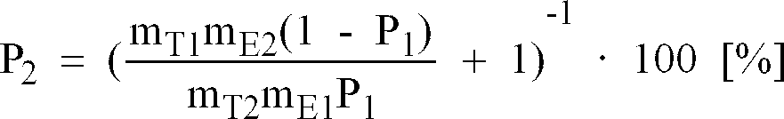
- the porosity P 1 of this electrode layer is determined using the method described above, where m T1 is the mass of the toluene taken up and m E1 is the mass of the electrode coating.
- m T1 is the mass of the toluene taken up
- m E1 is the mass of the electrode coating.
- the method according to the invention provides electrodes with improved mass transfer properties and lower diffusion resistances of the gas diffusion electrodes due to the advantageous macroporosity, which enable a higher cell performance and an improved use of the catalyst in operation with air compared to conventional methods.
- the process is inexpensive and easy to scale up on an industrial scale and can also be applied to other membrane materials, such as, for example, sulfonated polyether sulfone.
- FIG. 5 shows a schematic cross section through an electrode layer according to the invention.
- 1 denotes the polymer membrane and 2 the electrode layer.
- the electrode consists of the ion-conducting polymer and the finely divided Pt / C catalyst particles, which are not shown in FIG. 5, however.
- the pores of the layer are composed of small pores 4, which are formed during the evaporation of the solvents, and large pores 3. The large pores arise during the decomposition or dissolution of the pore former.
- EME units according to the invention (Examples 1 to 3) and two EME units according to US 5,211,984 produced as comparative examples. In all cases, an area concentration of platinum of 0.15 mg Pt / cm 2 was aimed for.
- a membrane made of Nafion® 117 in the Na + form was used as the solid electrolyte.
- the proton-conducting ionomer in the coating dispersion for the electrodes was converted into a thermoplastic modification by ion exchange with tetrabutylammonium hydroxide, which led to better adhesion of the coating to the polymer membrane.
- the mass ratio of catalyst / ionomer in the coating dispersion was set to a value of 2 in all examples.
- the value 1 was chosen for the mass ratio of pore former / ionomer in the examples according to the invention.
- an EME unit was produced as follows: A suspension of 3.1% by weight Pt / C catalyst (30% by weight Pt on carbon black Vulcan® XC-72) was produced. , 31.4% by weight of a 5% ionomer solution in 90% by weight of isopropanol and 10% by weight of water, 37.7% by weight of glycerol, 25.2% by weight of water and 2.5% by weight. -% Tetrabutylammoniumhydroxid prepared and brushed onto a PTFE support. This electrode precursor was dried at a temperature of 150 ° C.
- the electrode precursor was then placed on both sides of the ionomer membrane (Nafion® 117) and pressed at a temperature of 190 ° C. and a pressure of 100 bar. After hot pressing, the PTFE carrier was removed from the electrode.
- the ionomer membrane Nafion® 117
- the electrode adhered well to the membrane. After the protonation of the ionomer in 1 N sulfuric acid, the preparation of the electrodes was completed.
- the finished electrodes had a thickness of 5 ⁇ m, a total porosity of 20% and a platinum loading of 0.15 mg Pt / cm 2 .
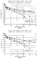
- FIGS. 1 to 3 The current-voltage curves of such a membrane fuel cell in air and oxygen operation are shown in FIGS. 1 to 3.
- Comparative Example 1 The coating dispersion of Comparative Example 1 was sprayed onto the Nafion® 117 membrane based on Protocol II from US Pat. No. 5,211,984.
- the spraying process was carried out using a template in order to obtain an electrode of the required size. This process can be repeated several times after the electrode has dried briefly. After the first electrode had completely dried after about 20 minutes at a temperature of 150 ° C., the counter electrode was applied in accordance with the same procedure.
- the back protonation was carried out in 1 N sulfuric acid.
- the current-voltage curves of this cell are shown in FIGS. 1 to 3 for air and oxygen operation.
- the total porosity of the electrodes produced in this way was 35%, their layer thickness 10 ⁇ m and their Pt concentration 0.15 mg Pt / cm 2 .
- the finished electrodes had a thickness of approximately 5 ⁇ m, a total porosity of 40% and a platinum loading of 0.15 mg Pt / cm 2 .
- the current-voltage curves of this EME unit are shown in Figure 4.
- a mixture of catalyst (20% by weight Pt on carbon black Vulcan® XC 72), ionomer solution, glycerol and a 20% solution of tetrabutylammonium hydroxide (TBAOH) in water was prepared.
- the paste was concentrated in a forced-air drying cabinet at 40 - 50 ° C. Then Li 2 CO 3 was added and stirred in. The mixture was dispersed using a three-roll mill. The resulting paste had the following composition: catalyst 7.67% Nafion (polymer) 2.56% Li 2 CO 3 2.6% TBAOH 1 % Glycerin 63.85% Alcohols, water 22.32%
- the viscosity of the paste was 1.86 Pas at a shear rate of 100 / s.
- the paste was printed through a VA steel sieve (80 mesh, 150 ⁇ m emulsion thickness, sieve cut area 5 cm ⁇ 5 cm) onto a Nafion 117 membrane in Na + form and dried at 140 ° C. This procedure was Repeated until a platinum load of 0.15 mg / cm 2 was reached. The back of the membrane was then made in the same way.
- the protonation and decomposition of the Li 2 CO 3 was carried out in 1 N sulfuric acid.
- the finished electrodes had a porosity of 31% and a platinum loading of 0.15 mgPt / cm 2 .
- a coating dispersion composed of 3.1% by weight of Pt / C catalyst (30% Pt), 30.9% by weight of a 5% ionomer solution in 90% by weight was used.
- the back protonation and the decomposition of the Li 2 CO 3 takes place in 1 N sulfuric acid.
- the current-voltage curves of this cell which show higher cell voltages and reduced mass transfer resistances as well as a significantly improved catalyst usage in air, are shown in FIG. 1.
- the total porosity of the electrode produced in this way was 65%.
- the platinum concentration was the same as that of the comparative examples.
- the average layer thickness was 15 - 20 ⁇ m.
- Example 2 Another electrode-membrane unit was produced as described in Example 1. In contrast to Example 1, 1.5% by weight ammonium oxalate was used as the pore former.
- the pore former was decomposed after the electrode had dried by raising the temperature of the membrane to 180 ° C. for 5 minutes.
- the subsequent back protonation was carried out as in Example 1 in 1 N sulfuric acid.
- the total porosity of the electrode produced in this way was 48%.
- Layer thickness and platinum concentration were the same as in Example 1.
- Example 2 Another electrode-membrane unit was produced as described in Example 1. In contrast to Example 1, 1.5% by weight ammonium carbonate was used as the pore former.
- the current-voltage curves of the electrode-membrane units produced in the above examples were recorded in a quasi-stationary galvanostatic manner.
- the EME units were covered on both sides with graphite paper as a gas distributor and current collector and in a graphite cell block clamped.
- the effective electrode area was 25 cm 2 .
- the cell temperature was kept constant at 75 ° C during the measurements.
- the anode-side hydrogen flow was 300 ml / min at a pressure of 1 bar and was moistened with water vapor in accordance with the equilibrium vapor pressure at 85 ° C.
- the cell On the cathode side, the cell was supplied with dry air or pure oxygen with a volume flow of 300 ml / min or 150 ml / min.
- Figures 1 to 4 each show the measured current-voltage curves of the electrode-membrane units according to the invention of Examples 1 to 3 (B1, B2, B3) in comparison to the current-voltage curves of the electrode-membrane units of Comparative Examples 1 to 4 (VB1, VB2, VB3, VB4).
- the electrode-membrane units according to the invention show significantly improved performance data in air operation. This also applies to comparative examples 3 and 4, both of which were produced using pore formers in the coating dispersion in a hot press process (VB3) and in a screen printing process (VB4).
Abstract
Description
- Die Erfindung betrifft eine poröse Gasdiffusionselektrode für Membranbrennstoffzellen auf einer ionenleitenden Polymermembran sowie ein Verfahren zu ihrer Herstellung. Der Einsatz von Gasdiffusionselektroden für Brennstoffzellen ist seit langem Stand der Technik. Für die Membranbrennstoffzelle wurden unter Verwendung von Elektrokatalysatoren auf der Basis von Platinbeziehungsweise Platinlegierungskatalysatoren auf leitfähigen Kohlenstoffträgern mehrere Verfahren zur Herstellung dieser Elektroden entwickelt.
- Die Optimierung des Kontaktes der drei Phasen Katalysator/Elektrolyt/Gas erweist sich gerade bei einem Festelektrolytsystem, wie es die Membranbrennstoffzelle mit einer ionenleitenden Membran als Elektrolyt darstellt, als besonders schwierig. Herkömmliche Gasdiffusionselektroden für den Einsatz in sauren Brennstoffzellen (z. B. der phosphorsauren Brennstoffzelle) werden im allgemeinen aus einer Mischung aus Polytetrafluorethylen (PTFE) und einem Elektrokatalysator aus platiniertem Ruß hergestellt, die auf eine Gasverteilerstruktur aufgezogen wird. Nach einem Tempervorgang erhält man so eine poröse, oberflächenreiche und teils hydrophile, teils hydrophobe Struktur der Elektrode, die im Betrieb in einer Brennstoffzelle mit einem flüssigen Elektrolyten einen guten Zugang der Arbeitsgase zu den elektrochemisch aktiven Zentren bei gleichzeitiger guter Benetzung durch den Elektrolyten ermöglicht. Der Zutritt des flüssigen Elektrolyten in die Tiefe der Elektrode erschließt eine ausreichend hohe Anzahl dieser elektrochemisch aktiven Zentren.
- Eine Membranbrennstoffzelle besteht aus einer Membran aus einem ionenleitenden Polymer, im folgenden auch kurz als Ionomer bezeichnet, mit beidseitig aufgebrachten Gasdiffusionselektroden als Kathode beziehungsweise Anode der Brennstoffzelle. Kathode und Anode enthalten geeignete feinteilige Elektrokatalysatoren zur Beschleunigung der Oxidation des Brennstoffes, in der Regel Wasserstoff, an der Anode und Reduktion des Sauerstoffs an der Kathode. Die Polymermembran bildet den Elektrolyten. Die Stromleitung durch die Membran erfolgt durch Transport von Protonen.
- Als katalytisch aktive Komponente des Elektrokatalysators wird bevorzugt Platin verwendet, welches noch mit einem oder mehreren Metallen der Gruppen VB, VIB, VIII und IB des Periodensystems der Elemente legiert sein kann. Die optimale Teilchengröße der katalytisch aktiven Legierungspartikel liegt im Bereich zwischen 2 und 10 nm. Zur Verwendung in den Elektroden von Brennstoffzellen werden die katalytisch aktiven Komponenten als Trägerkatalysatoren eingesetzt, das heißt die Legierungspartikel werden auf feinteiligen, elektrisch leitfähigen Kohlenstoffmaterialien wie zum Beispiel Ruß abgeschieden und in dieser Form in die Elektroden eingearbeitet. Alternativ besteht jedoch auch die Möglichkeit, die Legierungspartikel ohne Träger direkt in das Elektrodenmaterial einzubringen.
- In einer Membranbrennstoffzelle ist der Zugang des Elektrolyten in die Tiefe der Elektrode nicht ohne weiteres möglich. Die sogenannte Drei-Phasen-Zone bleibt ohne besondere Vorkehrungen auf den Bereich der Berührungsflächen zwischen Membran und Elektroden beschränkt.
- Aus der US 4,876,115 ist ein Verfahren zur Modifizierung kommerzieller Gasdiffusionselektroden bekannt, welche gewöhnlich in flüssigen Elektrolytsystemen eingesetzt werden. Diese Elektroden enthalten als Bindemittel hydrophobe Partikel aus polymerem PTFE, welches gleichzeitig die Benetzungseigenschaften der Elektrode reguliert und die Porosität der Elektrodenschicht stabilisiert. Zur Verbesserung des Kontaktes der drei Phasen Katalysator/Elektrolyt/Gas wird die vorgefertigte Elektrode mit einer Lösung eines protonenleitenden Materials durch Besprühen getränkt und dann mit der besprühten Seite mit der protonenleitenden Membran in Kontakt gebracht. Die Porosität der Elektrode wird nur durch die Zwischenräume zwischen den Partikeln des Elektrokatalysators und des hydrophoben PTFE gebildet.
- Wird die Elektrode mit einem Ionomer als protonenleitendes Material getränkt, so werden durch diese Vorbehandlung nur etwa 10 µm der Tiefe der Elektrode vom Elektrolyten erreicht. Dadurch bleibt ein Großteil des Elektrokatalysators in der im allgemeinen 100 bis 200 µm dicken Elektrode elektrochemisch ungenutzt. Mit diesen Elektroden können bei Flächenkonzentrationen von 0,35 bis 0,5 mg Pt/cm2 ähnliche Leistungsdaten wie mit konventionellen Elektroden mit Flächenkonzentrationen von 4 mg Pt/cm2 erzielt werden. Allerdings ist die maximale Konzentration bei Verwendung von Trägerkatalysatoren wegen der nur etwa 10 µm dicken elektrochemisch nutzbaren Schichtdicke auf Werte von etwa 0,5 mg Pt/cm2 beschränkt. Eine Leistungssteigerung durch Erhöhung der Flächenkonzentration an Katalysator ist damit nur im geringen Umfang möglich. Das schließt solche Elektroden von Anwendungen aus, die nach heutigem Kenntnisstand Katalysatorkonzentrationen von 4 mg Pt/cm2 und mehr erfordern, wie es zum Beispiel bei der Direkt-Methanol-Brennstoffzelle notwendig ist. Zur Herstellung solcher Elektroden mit höheren, elektrochemisch nutzbaren Konzentrationen muß zu trägerfreien Katalysatoren übergegangen werden.
- Von S. Escribano et al. (Editions de l'École Polytechnique de Montréal 1995, Seiten 135 - 143) wird die Herstellung von Elektroden für Membranbrennstoffzellen durch Sprühen einer Dispersion aus gelöstem Ionomer, Elektrokatalysator und PTFE auf die erwärmte Membran beschrieben. Die Elektroden sind nur wenige Mikrometer dick und weisen Poren mit Porenradien von etwa 50 nm auf. Auf die Elektrodenschichten werden abschließend Gasverteilerstrukturen heiß aufgepreßt. Dabei werden Temperaturen nahe dem Schmelzpunkt des PTFE (320 - 360°C) angewendet, um die PTFE-Partikel zu versintern. In diesen Elektroden dient PTFE als Binder und Hydrophobierungsmittel.
- Gemäß der US 5,211,984 verzichtet man auf PTFE als Binder und Hydrophobierungsmittel und erzielt eine nicht selbsttragende Elektrode, die nur aus Katalysator und Ionomerem besteht. Hierzu trägt man in einer Verfahrensvariante eine Suspension aus gelöstem Ionomeren und platiniertem Ruß auf einen PTFE-Träger auf, trocknet und verpreßt die vorformierte Elektrode mit dem PTFE-Träger auf eine Membran. Anschließend kann der PTFE-Träger rückstandsfrei abgezogen werden. Die Elektrode von etwa 10 µm Dicke haftet nach dem Heißpreßvorgang sehr gut auf der Membran.
- Die so hergestellte Elektrode besteht aus einer dichten Schicht aus Ionomerem und Elektrokatalysator. Die Elektrodenschicht enthält also im wesentlichen keine Poren und auch keine hydrophoben Zusätze. Die Elektrodenschicht ist daher auf eine maximale Dicke von 10 µm beschränkt. Diese maximale Schichtdicke gewährleistet noch einen ausreichend guten Transport des Sauerstoffs zu den Katalysatorpartikeln durch Diffusion durch das Ionomer. Bevorzugt wird eine Schichtdicke von weniger als 5 µm angestrebt. Auch diese Elektroden erzielen mit Flächenkonzentrationen von weniger als 0,35 mg Pt/cm2 ähnliche Leistungsdaten wie konventionelle Elektroden mit Konzentrationen von 4 mg Pt/cm2. Allerdings lassen sich auch bei diesen Elektroden bei Verwendung von Trägerkatalysatoren kaum Leistungssteigerungen erzielen, da die Flächenkonzentration wegen der geringen Schichtdicke nicht wesentlich erhöht werden kann.
- Ionomere Polymermembranen können in einer azidischen protonenleitenden H+-Form oder nach Austausch der Protonen gegen einwertige Ionen wie zum Beispiel Na+ und K+ in einer nichtazidischen Na+- oder K+-Form vorliegen. Die nichtazidische Form der Polymermembranen ist gewöhnlich gegenüber Temperaturbelastungen beständiger als ihre azidische Form. Für das Aufbringen der Elektrodenschichten werden die Membranen daher bevorzugt in ihrer Na+-Form verwendet - ebenso das in Lösung vorliegende Ionomer für die Elektrodenschicht. Im letzten Verfahrensschritt der Elektrodenherstellung wird das Polymermaterial durch sogenannte Rückprotonierung wieder in die azidische, protonenleitende Form überführt. Dies geschieht gewöhnlich durch Behandeln der Einheit aus Elektrode/Membran/Elektrode (EME-Einheit) in Schwefelsäure.
- Gemäß der US 5,211,984 kann die Robustheit der Elektrodenschichten weiter verbessert werden, wenn das gelöste Ionomer in der zur Herstellung der Elektrodenschicht verwendeten Suspension aus Katalysator und Ionomerlösung in einer thermoplastischen Form vorliegt. Die thermoplastische Form wird durch Ionenaustausch der protonenleitenden Form des Ionomers mit zum Beispiel Tetrabutylammonium-Kationen erhalten.
- Die US 4,469,579 beschreibt die Herstellung von porösen Elektroden auf Festelektrolytmembranen für die Verwendung in Natriumchlorid-Elektrolysezellen. Die Elektroden werden durch Besprühen der Membran mit einer Dispersion eines Elektrokatalysators in einer Lösung eines Ionomers hergestellt, wobei die Dispersion Porenbildner enthalten kann, um Poren für den Transport der bei der Elektrolyse gebildeten Gase zu erzeugen. Die Porenbildner werden nach Entfernung des Lösungsmittels, d.h. nach Trocknung der Elektroden aus diesen herausgelöst.
- Als Porenbildner werden Oxide, Hydroxide, Nitrate oder Carbide verschiedener Elemente mit Teilchengrößen zwischen 0,025 mm und 3 mm vorgeschlagen. Bevorzugt werden faserförmige Porenbildner mit Längen bis zu 50 mm eingesetzt. Ein bevorzugter Porenbildner ist Zinkoxid, welches mit Natronlauge nach Trocknung aus der Elektrode herausgelöst wird.
- Die DE-OS 15 46 701 (entsprechend US 3,385,780) offenbart ein Verfahren zur Herstellung einer porösen Elektrode für Brennstoffzellen. Gemäß diesem Verfahren wird ein feinteiliger Elektrokatalysator mit einem hydrophoben Polymer und einem Füllstoff zur Herstellung einer ersten Mischung innig vermischt. Eine zweite Mischung wird ohne den Elektrokatalysator hergestellt. Beide Mischungen werden in zwei getrennten Schichten in eine Presse eingeführt und dann bei einem Druck zwischen 350 und 840 bar verpreßt.
- Anschließend wird der Füllstoff entfernt, so daß ein einziger poröser Körper entsteht. Bei dem Füllstoff bzw. Porenbildner handelt es sich entweder um ein thermisch zersetzbares Material oder um ein Material, welches sich mit einer starken Base entfernen läßt. Als mögliche Füllstoffe werden Ammoniumoxalat, Ammoniumcarbonat, Kieselerdegel, Tonerde und Calciumcarbonat genannt. Als wasserabstoßendes Polymer wird zum Beispiel Polytetrafluorethylen verwendet.
- Die DE-OS 15 46 701 macht keine Aussage über die erzielten Porositäten der Elektroden. Aufgrund des hohen Preßdruckes ist jedoch davon auszugehen, daß das Elektrodenmaterial an sich sehr kompakt ist und seine Porosität sich nur aus den durch den Füllstoff hervorgerufenen Poren zusammensetzt.
- Die EP 0 622 861 A1 beschreibt ebenfalls eine Membran-Elektrodenstruktur. Zur Herstellung der Elektrode wird eine sogenannte Tinte aus einer 5 %igen Ionomerlösung in 50 % Isopropanol, 25 % Methanol und 20 % Wasser, 1-Methoxy, 2-Propanol und Pt/C-Katalysator (20 Gew.-% Pt auf Vulcan-Ruß) hergestellt. Die Tinte wird mit Hilfe eines Siebdruckverfahrens auf die Polymermembran aufgebracht. Elektrodenbeschichtung und Membran werden anschließend bei 127°C unter einem Druck von 20,7 bar miteinander verpreßt. In der Beschreibung dieser Patentanmeldung wird angeführt, daß die Elektrodenbeschichtung porös sein sollte. Es werden mittlere Porendurchmesser von 0,01 bis 50 µm, bevorzugt 0,1 bis 30 µm und Porositäten von 10 bis 99 %, bevorzugt 10 bis 60 %, angegeben. Für den Fachmann ist jedoch klar, daß diese Porositäten mit dem offenbarten Herstellverfahren keinesfalls realisiert werden können. Das gilt sowohl für die Porendurchmesser als auch für die Porositäten.
- Die Leistungsdaten von Brennstoffzellen hängen sehr stark von dem gewählten Oxidationsmittel ab. Maximale Werte werden bei Verwendung von reinem Sauerstoff erzielt. Beim Einsatz von Luft sinken die Leistungsdaten deutlich ab.
- Poymerelektrolyt-Brennstoffzellen, die Gegenstand dieser Erfindung sind, sollen hauptsächlich als Stromlieferanten in Fahrzeugen eingesetzt werden. Hierbei wird angestrebt, die Brennstoffzellen mit Luft zu betreiben. Daher ist die Optimierung der Gasdiffusionselektroden für den Luftbetrieb von entscheidender Wichtigkeit für den erfolgreichen Einsatz von Brennstoffzellen als Energielieferanten in Kraftfahrzeugen. Aufgabe der vorliegenden Erfindung ist es, Gasdiffusionselektroden für Membranbrennstoffzellen anzugeben, die durch einen optimierten Kontakt der drei Phasen Katalysator/Elektrolyt/Gas wesentlich verbesserte Leistungsdaten im Luftbetrieb aufweisen. Außerdem soll ein Verfahren zur Herstellung dieser Gasdiffusionselektrode angegeben werden.
- Diese Aufgabe wird gelöst durch eine poröse Gasdiffusionselektrode für Membranbrennstoffzellen auf einer protonenleitenden Polymermembran enthaltend einen feinteiligen Elektrokatalysator, welcher in einem protonenleitenden Polymer dispergiert ist. Die Elektrode ist dadurch gekennzeichnet, daß sie eine Porosität im Bereich zwischen 40 und 75% aufweist. Die Elektrode enthält keine hydrophoben Polymerbestandteile als Bindemittel.
- Die protonenleitende Polymermembran besteht bevorzugt aus einem Fluorkohlenstoff-Vinylether-Copolymer, welches auch als Perfluorkohlenstoff bezeichnet wird. Eine solche Membran wird zum Beispiel unter dem Handelsnamen Nafion® von E.I. duPont vertrieben.
- Die Elektrode ist sowohl als Kathode als auch als Anode geeignet. Als feinteilige Elektrokatalysatoren können alle auf dem Gebiet der Brennstoffzellen bekannten Katalysatoren als Trägerkatalysatoren oder trägerfreie Katalysatoren eingesetzt werden. Im Falle von Trägerkatalysatoren werden gewöhnlich feinteilige Ruße in graphitierter oder nicht graphitierter Form als Träger eingesetzt. Als katalytisch aktive Komponente dient Platin, welches mit weiteren Metallen wie Cobalt, Chrom, Wolfram, Molybdän, Eisen, Kupfer, Nickel und Ruthenium legiert sein kann. Ein bevorzugte Legierung ist zum Beispiel Platin/Cobalt/Chrom, welche mit Partikelgrößen im Bereich zwischen 2 und 10 nm auf den Rußen abgeschieden wird.
- Die Elektrode kann Schichtdicken im Bereich zwischen 5 und 100 µm aufweisen. Unterhalb einer Dicke von 5 µm wird die Elektrode wegen ihrer hohen Porosität zunehmend unzusammenhängend. Oberhalb von 100 µm Dicke nimmt trotz der hohen Porosität die elektrochemische Nutzbarkeit der Schicht langsam ab.
- Der große zur Verfügung stehende Schichtdickenbereich ermöglicht Flächenkonzentrationen an Elektrokatalysatoren zwischen 0,01 und 4 mg Pt/cm2. Zu diesem Zweck können geträgerte Elektrokatalysatoren mit 5 bis 40 Gew.-% Platin bezogen auf das Gesamtgewicht des Katalysators eingesetzt werden. Das Gewichtsverhältnis zwischen dem Ionomer der Schicht und dem darin dispergierten feinteiligen Elektrokatalysator kann zwischen 1 : 1 bis 1 : 10 gewählt werden. Bevorzugt sind Gewichtsverhältnisse zwischen 1 : 1,5 und 1 : 5. Bei zu hohem Anteil des Ionomers am Gesamtgewicht der Elektrode wird die Zugänglichkeit der Katalysatorpartikel für die Gase beeinträchtigt. Ein zu geringer Ionomeranteil führt dagegen zu einer ungenügenden Einbindung der Katalysatorpartikel in das Ionomermaterial.
- Zur Herstellung der erfindungsgemäßen Gasdiffusionselektrode wird eine Beschichtungsdispersion aus dem feinteiligen Elektrokatalysator in einer Lösung des ionenleitenden Polymers angesetzt und auf die zu beschichtende Polymermembran aufgesprüht.
- Zu diesem Zweck wird die ionenleitende Polymermembran in einer nichtazidischen, temperaturstabilen Modifikation eingesetzt und während der Sprühbeschichtung auf eine Temperatur im Bereich zwischen 130 und 170°C erwärmt. Neben dem Elektrokatalysator wird der Beschichtungsdispersion ein Porenbildner oder eine Mischung verschiedener Porenbildner mit einer mittleren Korngröße im Bereich zwischen 0,1 und 10 µm zugefügt. Nach dem Trocknen der Elektrodenbeschichtung wird das Ionomermaterial der Anordnung aus Elektrode/Membran/Elektrode durch Behandeln mit einer Säure, gewöhnlich 1 N Schwefelsäure, in die protonenleitende Form überführt.
- Bei dem Porenbildner kann es sich um einen Stoff handeln, der bei der notwendigen Rückprotonierung des Ionomermaterials durch die Säure aufgelöst wird. Bevorzugte Porenbildner dieser Art sind Carbonate und Bicarbonate der Alkali- und Erdalkalimetalle. Alternativ hierzu können auch solche Stoffe verwendet werden, die bei den gewählten Beschichtungstemperaturen von 130 bis 170°C thermisch zersetzt werden. Geeignet hierfür sind Stoffe mit einer Zersetzungstemperatur zwischen 50 und 170°C. Dabei kann es sich zum Beispiel um Ammoniumcarbonat oder Ammoniumbicarbonat handeln.
- Eine weitere Möglichkeit besteht in der Verwendung von Porenbildnern, die erst bei Temperaturen zersetzt werden, die oberhalb der Beschichtungstemperaturen liegen. Ein solcher Stoff ist zum Beispiel Ammoniumoxalat, welches erst bei 180°C thermisch zersetzt wird. Bei Verwendung solcher Porenbildner wird daher die EME-Einheit (Elektrode/Membran/Elektrode) vor der Rückprotonierung kurzzeitig auf eine Temperatur bis maximal 210°C erwärmt. Es hat sich gezeigt, daß das Ionomermaterial der EME-Einheit diese Maximaltemperatur bei kurzzeitiger Belastung bis etwa 10 Minuten Dauer ohne Schädigung übersteht, obwohl eine Dauerbelastung des Materials mit Temperaturen oberhalb von 180°C zur Unbrauchbarkeit für elektrochemische Zwecke führt.
- Die Porenbildner können teilweise in der Dispersion löslich sein. Beim Trocknen der Elektrodenbeschichtung kristallisieren die gelösten Anteile wieder aus, wobei ungelöste Anteile des Porenbildners als Kristallisationskeime dienen können.
- Das Verfahren ist sowohl für die Herstellung der Anode als auch der Kathode geeignet.
- Das beschriebene Herstellverfahren für die Gasdiffusionselektrode führt zu einer bimodalen Porenverteilung in der Elektrodenschicht. Die Gesamtporosität von 40 bis 75 % setzt sich daher aus kleinen Poren mit mittleren Durchmessern bis zu 0,5 µm und großen Poren mit mittleren Durchmessern von 1 bis 20 µm zusammen. Die kleinen Poren werden bei der Verdunstung der Lösungsmittel nach dem Aufsprühen der Beschichtungsdispersion auf die heiße Membran gebildet. Die großen Poren entstehen bei der Zersetzung oder der Herauslösung des Porenbildners. Ihr mittlerer Durchmesser kann daher durch die Korngröße des verwendeten Porenbildners beeinflußt werden.
- Die bimodale Porenverteilung bewirkt eine Verbesserung des Stofftransportes in der Elektrodenschicht. Durch die Makroporen kann das Reaktionsgas schnell in die Tiefe der Elektrodenschicht gelangen und das gebildete Reaktionswasser abgeführt werden. Die kleinen Poren übernehmen dann den Transport im ionenleitenden Polymer bis hin zu den Katalysatorpartikeln. Die hierbei zurückzulegenden Strecken sind nur noch kurz, so daß der verlangsamte Transport in den kleinen Poren die Leistungsfähigkeit der Elektrode nicht wesentlich beeinträchtigt. Eine deutliche Verbesserung des Transports in der Elektrodenschicht gegenüber konventionellen Beschichtungen wird erst bei Gesamtporositäten von mehr als 40 % beobachtet. Die Versorgung des Elektrokatalysators mit den Reaktionsmedien nimmt mit steigender Porosität zu. Mit steigender Porosität nimmt allerdings die Menge des verfügbaren Elektrokatalysators und des Ionomers in der Beschichtung ab. Damit verschlechtern sich mit steigender Porosität die Anbindung des Katalysators an das Ionomer sowie die ionische Leitfähigkeit der Beschichtung, so daß bei Porositäten oberhalb von 75 % sich die Leistungsdaten der Elektrodenschicht wieder verschlechtern.
- Zur Herstellung der Beschichtungsdispersion wird eine Lösung des azidischen, protonenleitenden Ionomers in einem geeigneten Lösungsmittel verwendet. Eine solche Lösung ist kommerziell erhältlich. Es handelt sich dabei um eine 5 Gew.-% Ionomer enthaltende Lösung in einer Mischung aus Isopropanol und Wasser im Gewichtsverhältnis 9 : 1. In dieser Lösung werden Elektrokatalysator und Porenbildner dispergiert. Der Porenbildner weist eine Korngröße zwischen 0,1 und 10 µm auf. Zur Einstellung der Viskosität und der Verdampfungsgeschwindigkeit können der Dispersion weitere Hilfsstoffe zugegeben werden. Geeignet hierfür ist zum Beispiel Glycerin. Vorteilhaft ist auch die Zugabe von Tetrabutylammoniumhydroxid, welches die Thermoplastizität und Temperaturstabilität des Elektrodenionomers erhöhen kann. Tetrabutylammoniumhydroxid wird der Beschichtungsdispersion als letzte Komponente zugefügt.
- Zur Beschichtung der Membran mit den Elektroden wird sie auf etwa 130 bis 170°C erwärmt und mit der Dispersion besprüht. Durch Sprühen der Dispersion auf die erwärmte Membran werden die Lösungsmittel forciert verdampft und die Elektrodenschicht getrocknet. Wurden Porenbildner verwendet, die sich schon bei den Temperaturen während der Beschichtung zersetzen, so ist nach der Trocknung die Porenbildung abgeschlossen. Andernfalls wird eine Elektrodenschicht erhalten, die zunächst nur eine gewisse Anfangsporosität aufweist, die vom Fachmann durch Auswahl der Lösungsmittel und der Membrantemperatur in engen Grenzen zwischen etwa 15 und 25 % variiert werden kann. Die Porenbildung wird in diesen Fällen erst durch Herauslösen des Porenbildners während der Rückprotonierung der EME-Einheit in Schwefelsäure beziehungsweise durch eine an die Trocknung anschließende Erwärmung bis auf eine Temperatur von maximal 210°C abgeschlossen.
- Abhängig vom Gewichtsverhältnis des verwendeten Porenbildners zum Ionomer läßt sich so die Porosität der Elektrodenschicht bis auf 75 % erhöhen. Das Gewichtsverhältnis Porenbildner/Ionomer kann im Bereich zwischen 0,10 : 1 und 10 : 1 variieren. Bei zu kleinem Anteil an Porenbildner erhöht sich die Porosität der fertigen Elektrode gegenüber ihrer Anfangsporosität nur unwesentlich. Gewichtsverhältnisse Porenbildner/Ionomer von größer als 10 : 1 führen zu mangelhaften Elektroden. Bevorzugt wird ein Gewichtsverhältnis von 1 : 1 angewendet.
- Das Auftragen der Elektrodendispersion in einem Heißsprühverfahren (Aufsprühen der Dispersion auf die erwärmte Membran) führt bei geeigneter Viskosität und Feststoffgehalt (Elektrokatalysator und Porenbildner) zu einer gut haftenden Elektrodenschicht von weniger als 100 µm Dicke und nach Rückprotonierung zu einer definierten Porosität.
- Die Porosität der Elektroden kann pyknometrisch durch Tränken der Elektroden mit Toluol im Vakuum und Ermitteln der Masseaufnahme an Toluol bestimmt werden. Die Porosität P der Elektroden errechnet sich hieraus als Verhältnis des Volumens des aufgenommenen Toluols zum Volumen der Elektrodenbeschichtung:

- Das Volumen der Elektrodenbeschichtung ergibt sich aus der Fläche der Elektrode und der unabhängig mit einem Rasterelektronenmikroskop bestimmten Schichtdicke.
- Im einzelnen wird die Porosität der Elektroden einer fertigen EME-Einheit wie folgt bestimmt:
- 1. Eine ausgestanzte EME-Scheibe (Durchmesser 25 mm) wird bei 100°C für 10 min. getrocknet und anschließend gewogen (Einwaage).
- 2. Überschichten der EME-Scheibe in einem Gefäß mit Toluol.
- 3. Evakuieren des Gefäßes bis zum Sieden des Toluols.
- 4. Belüften des Gefäßes und Abtupfen der EME-Scheibe mit einem Tuch zur Entfernung von Toluol auf der Oberfläche der Elektroden.
- 5. Wiegen der mit Toluol getränkten EME-Scheibe (Auswaage).
- 6. Bestimmen der in den Poren aufgenommenen Toluolmenge als Differenz von Aus- und Einwaage.
- 7. Berechnung der Porosität nach obiger Formel unter Berücksichtigung der Dichte von Toluol.
- Die porösen Elektroden gemäß der Erfindung weisen eine zerklüftete Oberfläche auf. Ihre Schichtdicke kann daher nur als ein Mittelwert aus rasterelektronenmikroskopischen Aufnahmen ermittelt werden. Bei hochporösen Schichten ist dies mit einer erheblichen Unsicherheit verbunden. In diesen Fällen können die Meßfehler durch Normierung der Messung mit Hilfe einer Schicht geringer Porosität vermindert werden. Hierzu wird eine EME-Einheit ohne Porenbildner angefertigt und gemäß der US 5,211,984 heiß verpreßt. Die So hergestellten Elektroden haben eine glatte Oberfläche. Ihre Dicke kann daher relativ genau bestimmt werden.
- Die Porosität P1 dieser Elektrodenschicht wird nach dem oben beschriebenen Verfahren ermittelt, wobei mT1 die Masse des aufgenommenen Toluols und mE1 die Masse der Elektrodenbeschichtung ist. Zur Bestimmung der Porosität P2 einer hochporösen Elektrodenbeschichtung wird diese ebenfalls mit Toluol getränkt und es werden die Massen mT2 und mE2 bestimmt. Auf eine Ausmessung der Schichtdicke wird jedoch verzichtet. Vielmehr berechnet sich jetzt die Porosität P2 unter Zuhilfenahme der Meßwerte der heiß gepreßten Elektrode zu:
- Das erfindungsgemäße Verfahren liefert Elektroden mit verbesserten Stofftransporteigenschaften und geringeren Diffusionswiderständen der Gasdiffusionselektroden aufgrund der vorteilhaften Makroporosität, welche eine höhere Zellenleistung und eine verbesserte Nutzung des Katalysators im Betrieb mit Luft im Vergleich zu herkömmlichen Verfahren ermöglichen. Das Verfahren ist preiswert und einfach in einen großtechnischen Maßstab zu übertragen und läßt sich auch auf andere Membranmaterialien, wie zum Beispiel sulfoniertes Polyethersulfon, anwenden.
- Die folgenden Beispiele verdeutlichen das erfindungsgemäße Herstellverfahren. Es zeigen:
- Figur 1:
- Vergleich der Leistungsdaten der konventionell hergestellten Elektrode-Membran-Einheit aus Vergleichsbeispiel 1 und Vergleichsbeispiel 2 mit den Leistungsdaten der erfindungsgemäßen Elektrode-Membran-Einheit nach Beispiel 1 bei Messungen mit Luft bzw. Sauerstoff als Kathodengas.
- Figur 2:
- Vergleich der Leistungsdaten der konventionell hergestellten Elektrode-Membran-Einheit aus Vergleichsbeispiel 1 und Vergleichsbeispiel 2 mit den Leistungsdaten der erfindungsgemäßen Elektrode-Membran-Einheit nach Beispiel 2 bei Messungen mit Luft bzw. Sauerstoff als Kathodengas.
- Figur 3:
- Vergleich der Leistungsdaten der konventionell hergestellten Elektrode-Membran-Einheit aus Vergleichsbeispiel 1 und Vergleichsbeispiel 2 mit den Leistungsdaten der erfindungsgemäßen Elektrode-Membran-Einheit nach Beispiel 3 bei Messungen mit Luft bzw. Sauerstoff als Kathodengas.
- Figur 4:
- Vergleich der Leistungsdaten der konventionell hergestellten Elektrode-Membran-Einheit aus Vergleichsbeispiel 3 und Vergleichsbeispiel 4 mit den Leistungsdaten der erfindungsgemäßen Elektrode-Membran-Einheit nach Beispiel 1 bei Messungen mit Luft bzw. Sauerstoff als Kathodengas.
- Figur 5:
- Schematische Darstellung des Querschnittes durch eine Elektrodenschicht.
- Figur 5 zeigt einen schematischen Querschnitt durch eine erfindungsgemäße Elektrodenschicht. 1 bezeichnet die Polymermembran und 2 die Elektrodenschicht. Die Elektrode besteht aus dem ionenleitenden Polymer und den feinteiligen Pt/C-Katalysatorpartikeln, die in Figur 5 jedoch nicht dargestellt sind. Die Poren der Schicht setzen sich aus kleinen Poren 4, welche bei der Verdampfung der Lösungsmittel gebildet werden, und großen Poren 3 zusammen. Die großen Poren entstehen bei der Zersetzung bzw. Auflösung des Porenbildners.
- In den folgenden Beispielen wurden erfindungsgemäße EME-Einheiten (Beispiele 1 bis 3) und zwei EME-Einheiten gemäß der US 5,211,984 als Vergleichsbeispiele hergestellt. In allen Fällen wurde eine Flächenkonzentration an Platin von 0,15 mg Pt/cm2 angestrebt.
- Als Festelektrolyt wurde eine Membran aus Nafion® 117 in der Na+-Form verwendet. Das protonenleitende Ionomer in der Beschichtungsdispersion für die Elektroden wurde jeweils durch Ionenaustausch mit Tetrabutylammoniumhydroxid in eine thermoplastische Modifikation überführt, die zu einer besseren Haftung der Beschichtung auf der Polymermembran führte.
- Das Massenverhältnis Katalysator/Ionomer in der Beschichtungsdispersion wurde in allen Beispielen auf einen Wert von 2 eingestellt. Für das Massenverhältnis Porenbildner/Ionomer wurde in den erfindungsgemäßen Beispielen der Wert 1 gewählt.
- In Anlehnung an Protocol I aus der US 5,211,984 wurde eine EME-Einheit wie folgt hergestellt: Es wurde eine Suspension aus 3,1 Gew.-% Pt/C-Katalysator (30 Gew.-% Pt auf Ruß Vulcan® XC-72), 31,4 Gew.-% einer 5 %igen Ionomerlösung in 90 Gew.-% Isopropanol und 10 Gew.-% Wasser, 37,7 Gew.% Glycerin, 25,2 Gew.-% Wasser und 2,5 Gew.-% Tetrabutylammoniumhydroxid angefertigt und auf einen PTFE-Träger aufgepinselt. Dieser Elektrodenvorläufer wurde bei einer Temperatur von 150°C getrocknet. Anschließend wurde der Elektrodenvorläufer beidseitig auf die Ionomermembran (Nafion® 117) aufgelegt und bei einer Temperatur von 190°C sowie einem Druck von 100 bar verpreßt. Nach dem Heißpressen wurde der PTFE-Träger von der Elektrode abgezogen.
- Die Elektrode haftete gut auf der Membran. Nach der Rückprotonierung des Ionomeren in 1 N Schwefelsäure war die Herstellung der Elektroden abgeschlossen.
- Die fertigen Elektroden hatten eine Dicke von 5 µm, eine Gesamtporosität von 20 % sowie eine Platinbeladung von 0,15 mg Pt/cm2.
- Die Strom-Spannungs-Kurven einer solchen Membranbrennstoffzelle im Luft- und Sauerstoffbetrieb sind in den Figuren 1 bis 3, dargestellt.
- Die Beschichtungsdispersion von Vergleichsbeispiel 1 wurde in Anlehnung an Protocol II aus US 5,211,984 auf die Nafion® 117-Membran aufgesprüht. Der Sprühvorgang erfolgte durch eine Schablone, um eine Elektrode der geforderten Größe zu erhalten. Dieser Vorgang kann nach einem kurzen Antrocknen der Elektrode mehrmals wiederholt werden. Nach dem vollständigen Trocknen der ersten Elektrode nach ca. 20 Minuten bei einer Temperatur von 150°C wurde die Gegenelektrode nach derselben Vorschrift aufgetragen. Die Rückprotonierung erfolgte in 1 N Schwefelsäure. Die Strom-Spannungs-Kurven dieser Zelle sind für den Luft- und Sauerstoffbetrieb in den Figuren 1 bis 3 dargestellt. Die Gesamtporosität der so hergestellten Elektroden betrug 35%, ihre Schichtdicke 10 µm und ihre Pt-Konzentration 0,15 mg Pt/cm2.
- Es wurde eine weitere EME-Einheit nach Vergleichsbeispiel 1 angefertigt. In Abwandlung zu Vergleichsbeispiel 1 wurde der Beschichtungsdispersion 1,5 Gew.-% Li2CO3 als Porenbildner zugefügt.
- Die fertigen Elektroden hatten eine Dicke von etwa 5 µm, eine Gesamtporosität von 40 % sowie eine Platinbeladung von 0,15 mgPt/cm2. Die Strom-Spannungs-Kurven dieser EME-Einheit sind in Figur 4 dargestellt.
- Es wurde eine Mischung aus Katalysator (20 Gew.-% Pt auf Ruß Vulcan® XC 72), Ionomerlösung, Glycerin und einer 20 %igen Lösung von Tetrabutylammoniumhydroxid (TBAOH) in Wasser hergestellt.
- Um eine für den Siebdruck geeignete Konsistenz einzustellen, wurde die Paste im Umlufttrockenschrank bei 40 - 50°C eingeengt. Anschließend wurde Li2CO3 zugegeben und untergerührt. Mit Hilfe eines Dreiwalzwerkes wurde die Mischung dispergiert. Die entstehende Paste hatte folgende Zusammensetzung:
Katalysator 7,67 % Nafion (Polymer) 2,56 % Li2CO3 2,6 % TBAOH 1 % Glycerin 63,85 % Alkohole, Wasser 22,32 % - Die Viskosität der Paste betrug 1,86 Pas bei einem Schergefälle von 100/s. Die Paste wurde durch ein VA-Stahl-Sieb (80 mesh, 150 µm Emulsionsstärke, Siebausschnittsfläche 5 cm x 5 cm) auf eine Nafion 117-Membran in Na+-Form aufgedruckt und bei 140°C getrocknet. Diese Prozedur wurde so lange wiederholt, bis eine Platinbeladung von 0,15 mg/cm2 erreicht war. Anschließend wurde die Rückseite der Membran auf die gleiche Weise hergestellt.
- Die Reprotonierung und die Zersetzung des Li2CO3 erfolgte in 1 N Schwefelsäure. Die fertigen Elektroden hatten eine Porosität von 31 % und eine Platinbeladung von 0,15 mgPt/cm2.
- Die Strom-Spannungs-Kurven einer solchen Membranbrennstoffzelle im Luft- und Sauerstoffbetrieb sind in Figur 4 als Kurve VB4 dargestellt.
- Zur Herstellung einer Elektrode-Membran-Einheit nach dem erfindungsgemäßen Verfahren wurde eine Beschichtungsdispersion aus 3,1 Gew.-% Pt/C-Katalysator (30 % Pt), 30,9 Gew.-% einer 5 %igen Ionomerlösung in 90 Gew.-% Isopropanol und 10 Gew.-% Wasser, 37,2 Gew.-% Glycerin und 24,8 Gew.-% Wasser, 2,5 Gew.-% Tetrabutylammoniumhydroxid sowie 1,5 Gew.-% Li2CO3 nach dem im Vergleichsbeispiel 2 beschriebenen Verfahren auf eine auf 150°C geheizte mit Natriumionen beladene Nafion® 117 Membran aufgesprüht. Die Rückprotonierung und die Zersetzung des Li2CO3 erfolgt in 1 N Schwefelsäure. Die Strom-Spannungs-Kurven dieser Zelle, die höhere Zellspannungen und verminderte Stofftransportwiderstände als auch eine wesentlich verbesserte Katalysatornutzung in Luft erkennen lassen, sind in Figur 1 dargestellt. Die Gesamtporosität der so hergestellten Elektrode betrug 65%. Die Platin-Konzentration war gleich den Konzentrationen der Vergleichsbeispiele. Die mittlere Schichtdicke lag bei 15 - 20 µm.
- Es wurde eine weitere Elektrode-Membran-Einheit wie in Beispiel 1 beschrieben hergestellt. Im Unterschied zu Beispiel 1 wurde als Porenbildner 1,5 Gew.-% Ammoniumoxalat verwendet.
- Die Zersetzung des Porenbildners erfolgte nach der Trocknung der Elektrode durch Erhöhen der Temperatur der Membran auf 180°C für die Dauer von 5 Minuten. Die anschließende Rückprotonierung wurde wie in Beispiel 1 in 1 N Schwefelsäure vorgenommen. Die Gesamtporosität der so hergestellten Elektrode betrug 48%. Schichtdicke und Platin-Konzentration waren gleich wie in Beispiel 1.
- Es wurde eine weitere Elektrode-Membran-Einheit wie in Beispiel 1 beschrieben hergestellt. Im Unterschied zu Beispiel 1 wurde als Porenbildner 1,5 Gew.-% Ammoniumcarbonat verwendet.
- Das Ammoniumcarbonat zersetzte sich unter Porenbildung während des Trocknungsvorganges. Die Rückprotonierung wurde wieder in 1 N Schwefelsäure vorgenommen. Die Gesamtporosität dieser Elektrode betrug 42%. Schichtdicke und Platin-Konzentration waren gleich wie in Beispiel 1.
- Die Strom-Spannungskurven der in den obigen Beispielen hergestellten Elektrode-Membran-Einheiten wurden galvanostatisch quasi-stationär aufgenommen. Hierzu wurden die EME-Einheiten auf beiden Seiten mit Graphit-Papier als Gasverteiler und Stromabnehmer belegt und in einen Graphit-Zellenblock eingespannt. Die wirksame Elektrodenfläche betrug 25 cm2.
- Die Zellentemperatur wurde während der Messungen auf 75°C konstant gehalten. Der anodenseitige Wasserstoffstrom betrug 300 ml/min bei einem Druck von 1 bar und wurde mit Wasserdampf entsprechend dem Gleichgewichtsdampfdruck bei 85°C befeuchtet. Kathodenseitig wurde die Zelle mit trockener Luft oder reinem Sauerstoff mit einem Volumenstrom von 300 ml/min beziehungsweise 150 ml/min versorgt.
- Die Figuren 1 bis 4 zeigen jeweils die gemessenen Strom-Spannungskurven der erfindungsgemäßen Elektrode-Membran-Einheiten der Beispiele 1 bis 3 (B1, B2, B3) im Vergleich zu den Strom-Spannungs-Kurven der Elektrode-Membran-Einheiten der Vergleichsbeispiele 1 bis 4 (VB1, VB2, VB3, VB4).
- Die erfindungsgemäßen Elektrode-Membraneinheiten zeigen aufgrund ihrer hohen Porosität wesentlich verbesserte Leistungsdaten bei Luftbetrieb. Dies gilt auch gegenüber den Vergleichsbeispielen 3 und 4, welche beide unter Verwendung von Porenbildner in der Beschichtungsdispersion in einem Heißpreßverfahren (VB3) und in einem Siebdruckverfahren (VB4) hergestellt wurden.
- Einzig die erfindungsgemäße Kombination aus Heißsprühen und Porenbildner führt zu bisher nicht zugänglichen Porositäten über 40 % bei verbesserten Leistungsdaten im Luftbetrieb.
Claims (11)
- Gasdiffusionselektrode für Membranbrennstoffzellen auf einer protonenleitenden Polymermembran bestehend aus einem feinteiligen Elektrokatalysator, welcher in einem protonenleitenden Polymer dispergiert ist,
dadurch gekennzeichnet,
daß die Elektrode eine Gesamtporosität von mehr als 40 und weniger als 75 % aufweist. - Gasdiffusionselektrode nach Anspruch 1,
dadurch gekennzeichnet,
daß die Elektrode eine Platin-Konzentration im Bereich zwischen 0,01 und 4 mg Pt/cm2 aufweist. - Gasdiffusionselektrode nach Anspruch 1 oder 2,
dadurch gekennzeichnet,
daß die Elektrode eine Dicke im Bereich zwischen 5 und 100 µm aufweist. - Verfahren zur Herstellung einer porösen Gasdiffusionselektrode für Membranbrennstoffzellen auf einer ionenleitenden Polymermembran durch Beschichten der Membran mit einer Dispersion aus einem feinteiligen Elektrokatalysator und wenigstens einem Porenbildner in einer Lösung eines ionenleitenden Polymers, wobei die Polymermembran in einer nichtazidischen, temperaturstabilen Modifikation vorliegt und während der Beschichtung auf eine Temperatur im Bereich zwischen 130 und 170°C erwärmt ist, Trocknen der Beschichtung und Rückprotonieren von Membran und Beschichtung in einer Säure,
dadurch gekennzeichnet,
daß der Porenbildner in feinteiliger Form mit einer mittleren Korngröße zwischen 0,1 und 10 µm vorliegt. - Verfahren nach Anspruch 4,
dadurch gekennzeichnet,
daß der Porenbildner in der Säure löslich ist. - Verfahren nach Anspruch 4,
dadurch gekennzeichnet,
daß der Porenbildner im Temperaturbereich zwischen 50 und 170°C thermisch zersetzbar ist. - Verfahren nach Anspruch 4,
dadurch gekennzeichnet,
daß der Porenbildner im Temperaturbereich zwischen 170 und 210°C thermisch zersetzbar ist und die Elektrodenbeschichtung vor dem Rückprotonieren für die Dauer von bis zu 5 Minuten auf eine Temperatur von bis zu 210°C erwärmt wird. - Verfahren nach Anspruch 4,
dadurch gekennzeichnet,
daß das Massenverhältnis von löslichem Ionomer und Porenbildner in der Beschichtungsdispersion im Bereich zwischen 0,01 : 1 und 10 : 1, bevorzugt 1 : 1 bis 1 : 2, gewählt wird. - Verfahren nach Anspruch 5,
dadurch gekennzeichnet,
daß als Porenbildner Carbonate der Alkali- oder Erdalkalimetalle verwendet werden. - Verfahren nach Anspruch 6,
dadurch gekennzeichnet,
daß als Porenbildner Ammoniumcarbonat verwendet wird. - Verfahren nach Anspruch 7,
dadurch gekennzeichnet,
daß als Porenbildner Ammoniumoxalat verwendet wird.
Applications Claiming Priority (2)
| Application Number | Priority Date | Filing Date | Title |
|---|---|---|---|
| DE19611510 | 1996-03-23 | ||
| DE19611510A DE19611510A1 (de) | 1996-03-23 | 1996-03-23 | Gasdiffusionselektrode für Membranbrennstoffzellen und Verfahren zu ihrer Herstellung |
Publications (3)
| Publication Number | Publication Date |
|---|---|
| EP0797265A2 true EP0797265A2 (de) | 1997-09-24 |
| EP0797265A3 EP0797265A3 (de) | 2000-07-26 |
| EP0797265B1 EP0797265B1 (de) | 2004-12-22 |
Family
ID=7789190
Family Applications (1)
| Application Number | Title | Priority Date | Filing Date |
|---|---|---|---|
| EP97104134A Expired - Lifetime EP0797265B1 (de) | 1996-03-23 | 1997-03-12 | Gasdiffusionselektrode für Membranbrennstoffzellen und Verfahren zu ihrer Herstellung |
Country Status (4)
| Country | Link |
|---|---|
| US (1) | US5861222A (de) |
| EP (1) | EP0797265B1 (de) |
| JP (1) | JP4056578B2 (de) |
| DE (2) | DE19611510A1 (de) |
Cited By (8)
| Publication number | Priority date | Publication date | Assignee | Title |
|---|---|---|---|---|
| WO2002015303A1 (fr) * | 2000-08-16 | 2002-02-21 | Matsushita Electric Industrial Co., Ltd. | Pile a combustible |
| WO2002027821A2 (en) * | 2000-09-27 | 2002-04-04 | Proton Energy Systems, Inc. | Electrode catalyst composition, electrode and membrane electrode assembly for electrochemical cells |
| WO2002080297A2 (de) * | 2001-03-30 | 2002-10-10 | Creavis Gesellschaft Für Technologie Und Innovation Mbh | Elektrolytmembran, diese umfassende membranelektrodeneinheiten, verfahren zur herstellung und spezielle verwendungen |
| US6531240B1 (en) | 1999-03-16 | 2003-03-11 | Johnson Matthey Public Limited Company | Gas diffusion substrates |
| EP0945910A3 (de) * | 1998-03-23 | 2004-01-07 | Umicore AG & Co. KG | Membran-Elektroden-Einheit für Polymer-Elektrolyt-Brennstoffzellen und Verfahren zu ihrer Herstellung |
| WO2004032263A2 (de) * | 2002-09-27 | 2004-04-15 | Bayer Materialscience Ag | Verfahren zur herstellung einer gasdiffusionselektrode |
| US7419740B2 (en) | 2000-07-29 | 2008-09-02 | Unicore Ag & Co. Kg | Membrane electrode unit for polymer electrolyte fuel cells and a process for the production thereof |
| EP2398101A1 (de) | 2010-06-17 | 2011-12-21 | Bayer MaterialScience AG | Gasdiffusionselektrode und Verfahren zu ihrer Herstellung |
Families Citing this family (85)
| Publication number | Priority date | Publication date | Assignee | Title |
|---|---|---|---|---|
| DE19721437A1 (de) * | 1997-05-21 | 1998-11-26 | Degussa | CO-toleranter Anodenkatalysator für PEM-Brennstoffzellen und Verfahren zu seiner Herstellung |
| DE19745904A1 (de) * | 1997-10-17 | 1999-04-22 | Hoechst Ag | Polymerstabilisierte Metallkolloid-Lösungen, Verfahren zu ihrer Herstellung und ihre Verwendung als Katalysatoren für Brennstoffzellen |
| JP3929146B2 (ja) * | 1997-11-07 | 2007-06-13 | 松下電器産業株式会社 | 固体高分子型燃料電池システム |
| US6297185B1 (en) * | 1998-02-23 | 2001-10-02 | T/J Technologies, Inc. | Catalyst |
| US6306536B1 (en) * | 1998-03-27 | 2001-10-23 | Ballard Power Systems Inc. | Method of reducing fuel cell performance degradation of an electrode comprising porous components |
| DE19837669A1 (de) * | 1998-08-20 | 2000-03-09 | Degussa | Katalysatorschicht für Polymer-Elektrolyt-Brennstoffzellen |
| JP4780814B2 (ja) * | 1998-12-15 | 2011-09-28 | 三洋電機株式会社 | 燃料電池 |
| EP1210868A1 (de) * | 1999-01-27 | 2002-06-05 | Seiichi Marumoto | Senkrechtes hydroponisches sprühsystem mit ultrahochdichtungsanlage und zuchtplatte |
| DE19910773A1 (de) | 1999-03-11 | 2000-09-28 | Degussa | Verfahren zum Aufbringen von Elektrodenschichten auf eine bandförmige Polymerelektrolytmembran für Brennstoffzellen |
| US6403245B1 (en) * | 1999-05-21 | 2002-06-11 | Microcoating Technologies, Inc. | Materials and processes for providing fuel cells and active membranes |
| PT1078959E (pt) * | 1999-08-27 | 2002-08-30 | Degussa | Negro de fumo metodo para a sua producao e sua utilizacao |
| DE19951936A1 (de) | 1999-10-28 | 2001-05-10 | Forschungszentrum Juelich Gmbh | Herstellung von Katalysatorschichten auf Membranen für Niedertemperatur-Brennstoffzellen |
| US6641948B1 (en) | 1999-11-17 | 2003-11-04 | Neah Power Systems Inc | Fuel cells having silicon substrates and/or sol-gel derived support structures |
| CA2397568A1 (en) * | 2000-01-18 | 2001-07-26 | Ramot University Authority For Applied Research And Industrial Development Ltd. | Novel fuels |
| US6447943B1 (en) * | 2000-01-18 | 2002-09-10 | Ramot University Authority For Applied Research & Industrial Development Ltd. | Fuel cell with proton conducting membrane with a pore size less than 30 nm |
| US6770394B2 (en) | 2000-02-11 | 2004-08-03 | The Texas A&M University System | Fuel cell with monolithic flow field-bipolar plate assembly and method for making and cooling a fuel cell stack |
| US6828054B2 (en) | 2000-02-11 | 2004-12-07 | The Texas A&M University System | Electronically conducting fuel cell component with directly bonded layers and method for making the same |
| DK1150369T3 (da) | 2000-04-28 | 2003-10-13 | Omg Ag & Co Kg | Gasfordelingsstrukturer og gasdiffusionselektroder til polymerelektrolyt-brændstofceller |
| DE10037074A1 (de) | 2000-07-29 | 2002-02-14 | Omg Ag & Co Kg | Tinte zur Herstellung von Membran-Elektroden-Einheiten für PEM-Brennstoffzellen |
| DE10037071A1 (de) * | 2000-07-29 | 2002-02-21 | Omg Ag & Co Kg | Edelmetall-Nanopartikel, Verfahren zu ihrer Herstellung und Verwendung |
| TW525314B (en) * | 2000-09-29 | 2003-03-21 | Sony Corp | Fuel cell and method for preparation thereof |
| DE10050467A1 (de) * | 2000-10-12 | 2002-05-16 | Omg Ag & Co Kg | Verfahren zur Herstellung einer Membran-Elektrodeneinheit für Brennstoffzellen |
| US6696382B1 (en) | 2000-11-14 | 2004-02-24 | The Regents Of The University Of California | Catalyst inks and method of application for direct methanol fuel cells |
| US20030091891A1 (en) * | 2001-01-16 | 2003-05-15 | Tomoaki Yoshida | Catalyst composition for cell, gas diffusion layer, and fuel cell comprising the same |
| EP1254711A1 (de) * | 2001-05-05 | 2002-11-06 | OMG AG & Co. KG | Edelmetallhaltiger Trägerkatalysator und Verfahren zu seiner Herstellung |
| EP1254712B1 (de) * | 2001-05-05 | 2005-07-20 | Umicore AG & Co. KG | Edelmetallhaltiger geträgerter Katalysator und Verfahren zu seiner Herstellung |
| DE10130441B4 (de) * | 2001-06-23 | 2005-01-05 | Uhde Gmbh | Verfahren zum Herstellen von Gasdiffusionselektroden |
| US6667756B2 (en) * | 2001-08-27 | 2003-12-23 | Xerox Corporation | Method of shifting an image or paper to reduce show through in duplex printing |
| US7094492B2 (en) * | 2001-10-11 | 2006-08-22 | Honda Giken Kogyo Kabushiki Kaisha | Electrode for polymer electrolyte fuel cell |
| US6686308B2 (en) * | 2001-12-03 | 2004-02-03 | 3M Innovative Properties Company | Supported nanoparticle catalyst |
| JP2005523561A (ja) * | 2002-02-28 | 2005-08-04 | トーマス ヘーリング | 層構造体および層構造体の製造方法 |
| DE60230979D1 (de) * | 2002-07-31 | 2009-03-12 | Umicore Ag & Co Kg | Wässrige Katalysatortinten und ihre Verwendung für die Herstellung von mit Katalysator beschichteten Substraten |
| JP3891484B2 (ja) * | 2002-09-05 | 2007-03-14 | 株式会社ノリタケカンパニーリミテド | 電解質膜およびその膜を備えた燃料電池 |
| US6695986B1 (en) | 2002-09-25 | 2004-02-24 | The United States Of America As Represented By The Secretary Of The Navy | Electrocatalytic enhancement with catalyst-modified carbon-silica composite aerogels |
| US20040107869A1 (en) * | 2002-12-10 | 2004-06-10 | 3M Innovative Properties Company | Catalyst ink |
| US20050014056A1 (en) * | 2003-07-14 | 2005-01-20 | Umicore Ag & Co. Kg | Membrane electrode unit for electrochemical equipment |
| EP1652258B1 (de) * | 2003-07-14 | 2010-09-15 | Umicore AG & Co. KG | Membran-elektroden-einheit für die wasserelektrolyse |
| TWI274084B (en) * | 2003-08-05 | 2007-02-21 | Lg Chemical Ltd | Hybrid membrane-electrode assembly with minimal interfacial resistance and preparation method thereof |
| JP4870328B2 (ja) * | 2003-10-10 | 2012-02-08 | ペルメレック電極株式会社 | 膜―電極接合体の製造方法 |
| DE602004023231D1 (de) * | 2003-10-29 | 2009-10-29 | Umicore Ag & Co Kg | Edelmetallkatalysator für die wasserelektrolyse |
| DE102004024845A1 (de) * | 2004-05-13 | 2005-12-08 | Volkswagen Ag | Verfahren zur Herstellung einer Katalysatorschicht für elektrochemische Zellen |
| DE102004024844A1 (de) * | 2004-05-13 | 2005-12-08 | Volkswagen Ag | Elektrodenpaste zur Herstellung einer Katalysatorschicht für eine elektrochemische Zelle sowie Verfahren zur Herstellung einer Katalysatorschicht |
| CN100405641C (zh) * | 2004-06-23 | 2008-07-23 | 比亚迪股份有限公司 | 质子交换膜燃料电池膜电极的制备方法 |
| US20080020253A1 (en) * | 2004-07-09 | 2008-01-24 | Ingo Neubert | Method for Producing a Membrane-Electrode Unit |
| US7422994B2 (en) * | 2005-01-05 | 2008-09-09 | Symyx Technologies, Inc. | Platinum-copper-tungsten fuel cell catalyst |
| JP2008534719A (ja) | 2005-03-30 | 2008-08-28 | ユミコア・アクチエンゲゼルシャフト・ウント・コムパニー・コマンディットゲゼルシャフト | 触媒層を製造するためのインク |
| GB0510119D0 (en) * | 2005-05-18 | 2005-06-22 | Johnson Matthey Plc | Polymer dispersion and electrocatalyst ink |
| JP4233051B2 (ja) * | 2005-09-30 | 2009-03-04 | 本田技研工業株式会社 | 燃料電池用電極層の製造方法 |
| US20070092784A1 (en) * | 2005-10-20 | 2007-04-26 | Dopp Robert B | Gas diffusion cathode using nanometer sized particles of transition metals for catalysis |
| US20080280190A1 (en) * | 2005-10-20 | 2008-11-13 | Robert Brian Dopp | Electrochemical catalysts |
| US7955755B2 (en) * | 2006-03-31 | 2011-06-07 | Quantumsphere, Inc. | Compositions of nanometal particles containing a metal or alloy and platinum particles |
| US20070227300A1 (en) * | 2006-03-31 | 2007-10-04 | Quantumsphere, Inc. | Compositions of nanometal particles containing a metal or alloy and platinum particles for use in fuel cells |
| US7785748B2 (en) * | 2006-04-03 | 2010-08-31 | University Of Delaware | Nano-based gas diffusion media |
| US20090215615A1 (en) * | 2006-07-11 | 2009-08-27 | 3M Innovative Properties Company | Method of forming supported nanoparticle catalysts |
| JP5011867B2 (ja) * | 2006-07-21 | 2012-08-29 | トヨタ自動車株式会社 | 燃料電池用の膜電極接合体の製造方法 |
| US8383293B2 (en) * | 2006-11-22 | 2013-02-26 | GM Global Technology Operations LLC | Supports for fuel cell catalysts based on transition metal silicides |
| JP4661825B2 (ja) * | 2007-05-09 | 2011-03-30 | トヨタ自動車株式会社 | 触媒粉体生成方法 |
| KR100874112B1 (ko) * | 2007-06-25 | 2008-12-15 | 한화석유화학 주식회사 | 연료전지용 촉매 잉크 및 이를 이용한 막-전극 복합체의제조방법 |
| DE102007031526B4 (de) * | 2007-07-06 | 2010-07-08 | Fraunhofer-Gesellschaft zur Förderung der angewandten Forschung e.V. | Verwendung einer Anode in einer Brennstoffzelle zur Oxidation von Ethanol und/oder zumindest eines C3 bis C10-haltigen Alkohols |
| US20090042091A1 (en) * | 2007-08-09 | 2009-02-12 | Matsushita Electric Industrial Co., Ltd. | Supported catalyst layers for direct oxidation fuel cells |
| WO2009089018A2 (en) | 2008-01-08 | 2009-07-16 | Sion Power Corporation | Porous electrodes and associated methods |
| TWI459622B (zh) * | 2007-11-15 | 2014-11-01 | Atomic Energy Council | Preparation of Thin Film Fuel Cell Electrode Using Nano Carbide Carrier Catalyst by Low Voltage Electrophoresis |
| KR20090058406A (ko) * | 2007-12-04 | 2009-06-09 | 한화석유화학 주식회사 | 연료전지용 독립 전극 촉매 층 및 이를 이용한 막-전극접합체의 제조방법 |
| US8501366B1 (en) | 2008-06-30 | 2013-08-06 | Sandia Corporation | Nanoengineered membrane electrode assembly interface |
| JP5277770B2 (ja) * | 2008-07-23 | 2013-08-28 | トヨタ自動車株式会社 | 固体高分子型燃料電池用膜電極接合体の製造方法、固体高分子型燃料電池用膜電極接合体、及び固体高分子型燃料電池 |
| JP5376217B2 (ja) * | 2009-02-13 | 2013-12-25 | 株式会社Gsユアサ | 燃料電池の電極材料用の粒子の製造方法、燃料電池用電極材料およびその製造方法、ならびに、燃料電池用電極の製造方法 |
| US20110206992A1 (en) * | 2009-08-28 | 2011-08-25 | Sion Power Corporation | Porous structures for energy storage devices |
| JP2013503439A (ja) | 2009-08-28 | 2013-01-31 | シオン・パワー・コーポレーション | 硫黄含有多孔質構造体を有する電気化学電池 |
| DE112011100210T5 (de) * | 2010-01-07 | 2012-11-08 | Kabushiki Kaisha Equos Research | Vorrichtung für die herstellung einer brennstoffzellenkatalysatorschicht, verfahren für die herstellung einer brennstoffzellenkatalysatorschicht, polyelektrolytlösung und verfahren für die herstellung einer polyelektrolytlösung |
| JP5565305B2 (ja) * | 2010-01-07 | 2014-08-06 | 株式会社エクォス・リサーチ | 燃料電池用触媒層の製造装置、燃料電池用触媒層の製造方法、高分子電解質溶液及び高分子電解質溶液の製造方法 |
| JP5174128B2 (ja) * | 2010-11-15 | 2013-04-03 | 三洋電機株式会社 | ガス拡散層、燃料電池用電極及び燃料電池 |
| EP2729979B1 (de) * | 2011-07-08 | 2017-12-13 | Audi AG | Platinarme elektrode |
| EP2608297A1 (de) | 2011-12-22 | 2013-06-26 | Umicore AG & Co. KG | Edelmetall-Oxidkatalysator für die Wasserlektrolyse |
| KR20130123189A (ko) * | 2012-05-02 | 2013-11-12 | 삼성전자주식회사 | 고체산화물 연료전지용 음극 지지체 및 그 제조방법과 이를 포함한 고체산화물 연료전지 |
| DE202013012667U1 (de) | 2012-05-31 | 2018-04-30 | Kyocera Corporation | Zelle, Zellenstapeleinheit, elektrochemisches Modul und elektrochemisches Gerät |
| KR101991149B1 (ko) | 2012-12-19 | 2019-06-19 | 시온 파워 코퍼레이션 | 전극 구조물 및 그의 제조 방법 |
| KR102092943B1 (ko) * | 2014-01-29 | 2020-04-14 | 삼성전자주식회사 | 전기 흡착 탈이온 장치용 전극 조성물, 및 이를 포함하는 전기 흡착 탈이온 장치용 전극 |
| EP3138144B1 (de) | 2014-05-01 | 2018-07-25 | Basf Se | Verfahren zur herstellung von elektroden, sowie hergestellte artikel |
| JP6632987B2 (ja) | 2014-10-24 | 2020-01-22 | 三井金属鉱業株式会社 | 燃料電池用電極触媒層、膜電極接合体及び固体高分子形燃料電池 |
| JP6931802B2 (ja) | 2015-11-19 | 2021-09-08 | パナソニックIpマネジメント株式会社 | 燃料電池用ガス拡散層及びその製造方法、膜電極接合体、並びに燃料電池 |
| DE102018204369A1 (de) * | 2018-03-22 | 2019-09-26 | Audi Ag | Verfahren zur Herstellung einer Elektrode mit erhöhter Porosität und eine entsprechende Elektrode |
| KR20210064638A (ko) * | 2019-11-26 | 2021-06-03 | 현대자동차주식회사 | 연료전지용 촉매 슬러리 및 이의 제조방법 |
| CN111082072B (zh) * | 2019-12-31 | 2022-01-11 | 上海神力科技有限公司 | 一种燃料电池用气体扩散层及其制备方法 |
| CN114236006A (zh) * | 2021-12-17 | 2022-03-25 | 河南省商业科学研究所有限责任公司 | 一种检测动物尿液中瘦肉精的方法 |
| CN114236005A (zh) * | 2021-12-17 | 2022-03-25 | 河南省商业科学研究所有限责任公司 | 一种检测动物性食品中瘦肉精的方法 |
Citations (12)
| Publication number | Priority date | Publication date | Assignee | Title |
|---|---|---|---|---|
| CH647004A5 (en) * | 1981-05-27 | 1984-12-28 | Bbc Brown Boveri & Cie | Method for coating a solid electrolyte present in the form of a sheet |
| US4581116A (en) * | 1984-12-04 | 1986-04-08 | The Dow Chemical Company | Gas diffusion composite electrode having novel hydrophilic layer |
| AT389020B (de) * | 1986-08-08 | 1989-10-10 | Peter Dipl Ing Dr Schuetz | Brennstoffzelle |
| US5211984A (en) * | 1991-02-19 | 1993-05-18 | The Regents Of The University Of California | Membrane catalyst layer for fuel cells |
| EP0560295A1 (de) * | 1992-03-09 | 1993-09-15 | Hitachi, Ltd. | Wasserstoff-Sauerstoff-Brennstoffzelle mit polymeren Elektrolyten |
| WO1994014203A1 (de) * | 1992-12-07 | 1994-06-23 | Fraunhofer-Gesellschaft zur Förderung der angewandten Forschung e.V. | Elektrodenmembran |
| EP0622861A1 (de) * | 1993-04-26 | 1994-11-02 | E.I. Du Pont De Nemours & Company Incorporated | Membran-Elektrode Struktur |
| US5399184A (en) * | 1992-05-01 | 1995-03-21 | Chlorine Engineers Corp., Ltd. | Method for fabricating gas diffusion electrode assembly for fuel cells |
| WO1995020691A1 (en) * | 1994-01-28 | 1995-08-03 | United Technologies Corporation | High performance electrolytic cell electrode structures and a process for preparing such electrode structures |
| EP0718903A1 (de) * | 1994-12-07 | 1996-06-26 | Japan Gore-Tex, Inc. | Ionenaustauschmembran-Elektrodeeinheit für eine elektrochemische Zelle |
| WO1997013287A2 (en) * | 1995-10-06 | 1997-04-10 | The Dow Chemical Company | Flow field structures for membrane electrode assemblies of fuel cells |
| EP0785588A2 (de) * | 1996-01-19 | 1997-07-23 | Toyota Jidosha Kabushiki Kaisha | Verfahren zur Herstellung einer Elektrode oder einem Verbundkörper Elektrode-Elektrolytmembran und Elektrode für Brennstoffzelle |
Family Cites Families (7)
| Publication number | Priority date | Publication date | Assignee | Title |
|---|---|---|---|---|
| US3385780A (en) * | 1964-07-10 | 1968-05-28 | Exxon Research Engineering Co | Porous dual structure electrode |
| US4469579A (en) * | 1981-06-26 | 1984-09-04 | Diamond Shamrock Corporation | Solid polymer electrolytes and electrode bonded with hydrophylic fluorocopolymers |
| NL8301780A (nl) * | 1983-05-19 | 1984-12-17 | Electrochem Energieconversie | Poreuze elektrode. |
| US4876115A (en) * | 1987-01-30 | 1989-10-24 | United States Department Of Energy | Electrode assembly for use in a solid polymer electrolyte fuel cell |
| US5272017A (en) * | 1992-04-03 | 1993-12-21 | General Motors Corporation | Membrane-electrode assemblies for electrochemical cells |
| DE4426973C1 (de) * | 1994-07-29 | 1996-03-28 | Degussa | Verfahren zur Herstellung eines als Brennstoffzellenelektrode einsetzbaren Plattinlegierungskatalysators |
| US5523177A (en) * | 1994-10-12 | 1996-06-04 | Giner, Inc. | Membrane-electrode assembly for a direct methanol fuel cell |
-
1996
- 1996-03-23 DE DE19611510A patent/DE19611510A1/de not_active Ceased
-
1997
- 1997-03-12 DE DE59712123T patent/DE59712123D1/de not_active Expired - Lifetime
- 1997-03-12 EP EP97104134A patent/EP0797265B1/de not_active Expired - Lifetime
- 1997-03-21 JP JP06713297A patent/JP4056578B2/ja not_active Expired - Fee Related
- 1997-03-24 US US08/822,864 patent/US5861222A/en not_active Expired - Lifetime
Patent Citations (12)
| Publication number | Priority date | Publication date | Assignee | Title |
|---|---|---|---|---|
| CH647004A5 (en) * | 1981-05-27 | 1984-12-28 | Bbc Brown Boveri & Cie | Method for coating a solid electrolyte present in the form of a sheet |
| US4581116A (en) * | 1984-12-04 | 1986-04-08 | The Dow Chemical Company | Gas diffusion composite electrode having novel hydrophilic layer |
| AT389020B (de) * | 1986-08-08 | 1989-10-10 | Peter Dipl Ing Dr Schuetz | Brennstoffzelle |
| US5211984A (en) * | 1991-02-19 | 1993-05-18 | The Regents Of The University Of California | Membrane catalyst layer for fuel cells |
| EP0560295A1 (de) * | 1992-03-09 | 1993-09-15 | Hitachi, Ltd. | Wasserstoff-Sauerstoff-Brennstoffzelle mit polymeren Elektrolyten |
| US5399184A (en) * | 1992-05-01 | 1995-03-21 | Chlorine Engineers Corp., Ltd. | Method for fabricating gas diffusion electrode assembly for fuel cells |
| WO1994014203A1 (de) * | 1992-12-07 | 1994-06-23 | Fraunhofer-Gesellschaft zur Förderung der angewandten Forschung e.V. | Elektrodenmembran |
| EP0622861A1 (de) * | 1993-04-26 | 1994-11-02 | E.I. Du Pont De Nemours & Company Incorporated | Membran-Elektrode Struktur |
| WO1995020691A1 (en) * | 1994-01-28 | 1995-08-03 | United Technologies Corporation | High performance electrolytic cell electrode structures and a process for preparing such electrode structures |
| EP0718903A1 (de) * | 1994-12-07 | 1996-06-26 | Japan Gore-Tex, Inc. | Ionenaustauschmembran-Elektrodeeinheit für eine elektrochemische Zelle |
| WO1997013287A2 (en) * | 1995-10-06 | 1997-04-10 | The Dow Chemical Company | Flow field structures for membrane electrode assemblies of fuel cells |
| EP0785588A2 (de) * | 1996-01-19 | 1997-07-23 | Toyota Jidosha Kabushiki Kaisha | Verfahren zur Herstellung einer Elektrode oder einem Verbundkörper Elektrode-Elektrolytmembran und Elektrode für Brennstoffzelle |
Cited By (16)
| Publication number | Priority date | Publication date | Assignee | Title |
|---|---|---|---|---|
| EP0945910A3 (de) * | 1998-03-23 | 2004-01-07 | Umicore AG & Co. KG | Membran-Elektroden-Einheit für Polymer-Elektrolyt-Brennstoffzellen und Verfahren zu ihrer Herstellung |
| US6531240B1 (en) | 1999-03-16 | 2003-03-11 | Johnson Matthey Public Limited Company | Gas diffusion substrates |
| US7419740B2 (en) | 2000-07-29 | 2008-09-02 | Unicore Ag & Co. Kg | Membrane electrode unit for polymer electrolyte fuel cells and a process for the production thereof |
| WO2002015303A1 (fr) * | 2000-08-16 | 2002-02-21 | Matsushita Electric Industrial Co., Ltd. | Pile a combustible |
| EP1320140A1 (de) * | 2000-08-16 | 2003-06-18 | Matsushita Electric Industrial Co., Ltd. | Brennstoffzelle |
| EP1320140A4 (de) * | 2000-08-16 | 2007-10-10 | Matsushita Electric Ind Co Ltd | Brennstoffzelle |
| US6828056B2 (en) | 2000-09-27 | 2004-12-07 | Proton Energy Systems, Inc. | Electrode catalyst composition, electrode, and membrane electrode assembly for electrochemical cells |
| WO2002027821A2 (en) * | 2000-09-27 | 2002-04-04 | Proton Energy Systems, Inc. | Electrode catalyst composition, electrode and membrane electrode assembly for electrochemical cells |
| WO2002027821A3 (en) * | 2000-09-27 | 2002-10-17 | Proton Energy Sys Inc | Electrode catalyst composition, electrode and membrane electrode assembly for electrochemical cells |
| WO2002080297A3 (de) * | 2001-03-30 | 2003-02-20 | Creavis Tech & Innovation Gmbh | Elektrolytmembran, diese umfassende membranelektrodeneinheiten, verfahren zur herstellung und spezielle verwendungen |
| WO2002080297A2 (de) * | 2001-03-30 | 2002-10-10 | Creavis Gesellschaft Für Technologie Und Innovation Mbh | Elektrolytmembran, diese umfassende membranelektrodeneinheiten, verfahren zur herstellung und spezielle verwendungen |
| WO2004032263A3 (de) * | 2002-09-27 | 2005-02-17 | Bayer Materialscience Ag | Verfahren zur herstellung einer gasdiffusionselektrode |
| WO2004032263A2 (de) * | 2002-09-27 | 2004-04-15 | Bayer Materialscience Ag | Verfahren zur herstellung einer gasdiffusionselektrode |
| EP2398101A1 (de) | 2010-06-17 | 2011-12-21 | Bayer MaterialScience AG | Gasdiffusionselektrode und Verfahren zu ihrer Herstellung |
| DE102010030203A1 (de) | 2010-06-17 | 2011-12-22 | Bayer Materialscience Ag | Gasdiffusionselektrode und Verfahren zu ihrer Herstellung |
| US10224552B2 (en) | 2010-06-17 | 2019-03-05 | Covestro Ag | Gas diffusion electrode and process for production thereof |
Also Published As
| Publication number | Publication date |
|---|---|
| DE59712123D1 (de) | 2005-01-27 |
| DE19611510A1 (de) | 1997-09-25 |
| JP4056578B2 (ja) | 2008-03-05 |
| US5861222A (en) | 1999-01-19 |
| EP0797265A3 (de) | 2000-07-26 |
| EP0797265B1 (de) | 2004-12-22 |
| JPH103929A (ja) | 1998-01-06 |
Similar Documents
| Publication | Publication Date | Title |
|---|---|---|
| EP0797265B1 (de) | Gasdiffusionselektrode für Membranbrennstoffzellen und Verfahren zu ihrer Herstellung | |
| EP1176653B1 (de) | Membran-Elektrodeneinheit für Polymerelektrolyt-Brennstoffzellen und Verfahren zu ihrer Herstellung | |
| EP1150369B1 (de) | Gasverteilerstrukturen und Gasdiffusionselektroden für Polymerelektrolyt-Brennstoffzellen | |
| EP1198021B1 (de) | Verfahren zur Herstellung einer Membran-Elektrodeneinheit für Brennstoffzellen | |
| DE19812592B4 (de) | Membran-Elektroden-Einheit für Polymer-Elektrolyt-Brennstoffzellen, Verfahren zu ihrer Herstellung sowie Tinte | |
| EP0987777B1 (de) | Katalysatorschicht für Polymer-Elektrolyt-Brennstoffzellen | |
| DE10007990B4 (de) | Verfahren zum Herstellen eines Elektrodenaufbaus und eines kombinierten Elektrolyt- und Elektrodenaufbaus sowie ein Elektrodenaufbau und ein kombinierter Elektrolyt- und Elektrodenaufbau für elektrochemische Zellen | |
| DE69829933T2 (de) | Elektrode aus Festpolymerelektrolyt-Katalysator Kompositen, Elektrode für Brennstoffzellen und Verfahren zur Herstellung dieser Elektroden | |
| DE19958959B4 (de) | Brennstoffzellenelektrode und Verfahren zur Herstellung einer Brennstoffzellenelektrode | |
| DE10159476A1 (de) | Verfahren zur Herstellung von Membran-Elektrodeneinheiten für Brennstoffzellen | |
| DE112004002061T5 (de) | Verfahren zur Herstellung von Membranen und Membranelektrodenanordnungen mit einem Wasserstoffperoxid-zersetzungskatalysator | |
| EP1261057B1 (de) | Verfahren zur Herstellung einer Membran-Elektrodeneinheit und dadurch hergestellte Membran-Elektrodeneinheit | |
| EP3596767B1 (de) | Katalytische zusammensetzung, verfahren zu ihrer herstellung, ihre verwendung zur herstellung einer brennstoffzellenelektrode sowie brennstoffzelle mit einer solchen | |
| WO2000013243A2 (de) | Verbesserte gasdiffusionselektrode, herstellungsverfahren dazu und verfahren zur hydrophobierung einer gasdiffusionselektrode | |
| WO2015139791A1 (de) | Katalysatorschicht für eine brennstoffzelle und verfahren zur herstellung einer solchen | |
| DE19701174A1 (de) | Verfahren zur Messung der für eine Reaktion verfügbaren spezifischen Oberflächengröße eines Edelmetall-Katalysators in der Elektrode einer Polymer-Elektrolyt-Membran-Brennstoffzelle und zur Bemessung der Katalysatorschicht für die Elektrode dieser Brennstoffzelle | |
| DE602004010021T2 (de) | Tinte zur Herstellung einer Katalysatorschicht, Elektrode und Membran-Elektrode-Anordnung in denen solche Tinte verwendet wird | |
| EP1601037B1 (de) | Membran-Elektroden-Einheit für Direkt-Methanol-Brennstoffzellen (DMFC) | |
| DE102016220653A1 (de) | Korrosionsbeständiger katalysator | |
| DE10052189B4 (de) | Mehrschichtige Gasdiffusionselektrode einer Polymerelektrolytmembran-Brennstoffzelle, Membranelektrodenanordnung, Verfahren zur Herstellung einer Gasdiffusionselektrode und einer Membranelektrodenanordnung sowie Verwendung der Membranelektrodenanordnung | |
| EP1150370A2 (de) | Gasverteilerstrukturen und Gasdiffusionselektroden für Polymerelektrolyt-Brennstoffzellen | |
| DE10052190B4 (de) | Gasdiffusionselektrode, Membranelektrodenanordnung, Verfahren zur Herstellung einer Gasdiffusionselektrode und Verwendung einer Membranelektrodenanordnung | |
| DE102004024845A1 (de) | Verfahren zur Herstellung einer Katalysatorschicht für elektrochemische Zellen | |
| DE102018103705A1 (de) | Verfahren zur Herstellung von Katalysatortinte, und Katalysatorkomposit | |
| DE112008001878B4 (de) | Brennstoffzelle und die katalytische Schicht derselben bildendes Elektrodenpulver |
Legal Events
| Date | Code | Title | Description |
|---|---|---|---|
| PUAI | Public reference made under article 153(3) epc to a published international application that has entered the european phase |
Free format text: ORIGINAL CODE: 0009012 |
|
| AK | Designated contracting states |
Kind code of ref document: A2 Designated state(s): DE FR GB IT NL |
|
| RAP1 | Party data changed (applicant data changed or rights of an application transferred) |
Owner name: DEGUSSA-HUELS AKTIENGESELLSCHAFT |
|
| RAP3 | Party data changed (applicant data changed or rights of an application transferred) |
Owner name: DEGUSSA-HUELS AKTIENGESELLSCHAFT |
|
| PUAL | Search report despatched |
Free format text: ORIGINAL CODE: 0009013 |
|
| AK | Designated contracting states |
Kind code of ref document: A3 Designated state(s): DE FR GB IT NL |
|
| 17P | Request for examination filed |
Effective date: 20000623 |
|
| RAP1 | Party data changed (applicant data changed or rights of an application transferred) |
Owner name: DMC2 DEGUSSA METALS CATALYSTS CERDEC AG |
|
| 17Q | First examination report despatched |
Effective date: 20010328 |
|
| RAP1 | Party data changed (applicant data changed or rights of an application transferred) |
Owner name: OMG AG & CO. KG |
|
| RAP1 | Party data changed (applicant data changed or rights of an application transferred) |
Owner name: UMICORE AG & CO. KG |
|
| GRAP | Despatch of communication of intention to grant a patent |
Free format text: ORIGINAL CODE: EPIDOSNIGR1 |
|
| GRAS | Grant fee paid |
Free format text: ORIGINAL CODE: EPIDOSNIGR3 |
|
| GRAA | (expected) grant |
Free format text: ORIGINAL CODE: 0009210 |
|
| AK | Designated contracting states |
Kind code of ref document: B1 Designated state(s): DE FR GB IT NL |
|
| REG | Reference to a national code |
Ref country code: GB Ref legal event code: FG4D Free format text: NOT ENGLISH |
|
| REF | Corresponds to: |
Ref document number: 59712123 Country of ref document: DE Date of ref document: 20050127 Kind code of ref document: P |
|
| GBT | Gb: translation of ep patent filed (gb section 77(6)(a)/1977) |
Effective date: 20050405 |
|
| PLBE | No opposition filed within time limit |
Free format text: ORIGINAL CODE: 0009261 |
|
| STAA | Information on the status of an ep patent application or granted ep patent |
Free format text: STATUS: NO OPPOSITION FILED WITHIN TIME LIMIT |
|
| 26N | No opposition filed |
Effective date: 20050923 |
|
| ET | Fr: translation filed | ||
| PGFP | Annual fee paid to national office [announced via postgrant information from national office to epo] |
Ref country code: IT Payment date: 20100324 Year of fee payment: 14 Ref country code: FR Payment date: 20100402 Year of fee payment: 14 |
|
| PGFP | Annual fee paid to national office [announced via postgrant information from national office to epo] |
Ref country code: GB Payment date: 20100322 Year of fee payment: 14 |
|
| PGFP | Annual fee paid to national office [announced via postgrant information from national office to epo] |
Ref country code: NL Payment date: 20100315 Year of fee payment: 14 |
|
| REG | Reference to a national code |
Ref country code: NL Ref legal event code: V1 Effective date: 20111001 |
|
| GBPC | Gb: european patent ceased through non-payment of renewal fee |
Effective date: 20110312 |
|
| REG | Reference to a national code |
Ref country code: FR Ref legal event code: ST Effective date: 20111130 |
|
| PG25 | Lapsed in a contracting state [announced via postgrant information from national office to epo] |
Ref country code: NL Free format text: LAPSE BECAUSE OF NON-PAYMENT OF DUE FEES Effective date: 20111001 Ref country code: FR Free format text: LAPSE BECAUSE OF NON-PAYMENT OF DUE FEES Effective date: 20110331 |
|
| PG25 | Lapsed in a contracting state [announced via postgrant information from national office to epo] |
Ref country code: GB Free format text: LAPSE BECAUSE OF NON-PAYMENT OF DUE FEES Effective date: 20110312 Ref country code: IT Free format text: LAPSE BECAUSE OF NON-PAYMENT OF DUE FEES Effective date: 20110312 |
|
| PGFP | Annual fee paid to national office [announced via postgrant information from national office to epo] |
Ref country code: DE Payment date: 20150305 Year of fee payment: 19 |
|
| REG | Reference to a national code |
Ref country code: DE Ref legal event code: R119 Ref document number: 59712123 Country of ref document: DE |
|
| PG25 | Lapsed in a contracting state [announced via postgrant information from national office to epo] |
Ref country code: DE Free format text: LAPSE BECAUSE OF NON-PAYMENT OF DUE FEES Effective date: 20161001 |