EP0802642A2 - Optical transmission system using dispersion compensation - Google Patents
Optical transmission system using dispersion compensation Download PDFInfo
- Publication number
- EP0802642A2 EP0802642A2 EP96118761A EP96118761A EP0802642A2 EP 0802642 A2 EP0802642 A2 EP 0802642A2 EP 96118761 A EP96118761 A EP 96118761A EP 96118761 A EP96118761 A EP 96118761A EP 0802642 A2 EP0802642 A2 EP 0802642A2
- Authority
- EP
- European Patent Office
- Prior art keywords
- dispersion
- fiber
- chirping
- optical
- parameter
- Prior art date
- Legal status (The legal status is an assumption and is not a legal conclusion. Google has not performed a legal analysis and makes no representation as to the accuracy of the status listed.)
- Granted
Links
Images


Classifications
-
- H—ELECTRICITY
- H04—ELECTRIC COMMUNICATION TECHNIQUE
- H04B—TRANSMISSION
- H04B10/00—Transmission systems employing electromagnetic waves other than radio-waves, e.g. infrared, visible or ultraviolet light, or employing corpuscular radiation, e.g. quantum communication
- H04B10/25—Arrangements specific to fibre transmission
- H04B10/2507—Arrangements specific to fibre transmission for the reduction or elimination of distortion or dispersion
- H04B10/2513—Arrangements specific to fibre transmission for the reduction or elimination of distortion or dispersion due to chromatic dispersion
- H04B10/2519—Arrangements specific to fibre transmission for the reduction or elimination of distortion or dispersion due to chromatic dispersion using Bragg gratings
-
- H—ELECTRICITY
- H04—ELECTRIC COMMUNICATION TECHNIQUE
- H04B—TRANSMISSION
- H04B10/00—Transmission systems employing electromagnetic waves other than radio-waves, e.g. infrared, visible or ultraviolet light, or employing corpuscular radiation, e.g. quantum communication
- H04B10/25—Arrangements specific to fibre transmission
- H04B10/2507—Arrangements specific to fibre transmission for the reduction or elimination of distortion or dispersion
- H04B10/2513—Arrangements specific to fibre transmission for the reduction or elimination of distortion or dispersion due to chromatic dispersion
- H04B10/25137—Arrangements specific to fibre transmission for the reduction or elimination of distortion or dispersion due to chromatic dispersion using pulse shaping at the transmitter, e.g. pre-chirping or dispersion supported transmission [DST]
-
- H—ELECTRICITY
- H04—ELECTRIC COMMUNICATION TECHNIQUE
- H04B—TRANSMISSION
- H04B2210/00—Indexing scheme relating to optical transmission systems
- H04B2210/25—Distortion or dispersion compensation
- H04B2210/252—Distortion or dispersion compensation after the transmission line, i.e. post-compensation
-
- H—ELECTRICITY
- H04—ELECTRIC COMMUNICATION TECHNIQUE
- H04B—TRANSMISSION
- H04B2210/00—Indexing scheme relating to optical transmission systems
- H04B2210/25—Distortion or dispersion compensation
- H04B2210/254—Distortion or dispersion compensation before the transmission line, i.e. pre-compensation
Definitions
- the present invention relates to an optical transmission system using optical fiber.
- optical amplifiers has introduced a new problem of nonlinear effects because of increased optical input levels to the fiber.
- One is self-phase modulation (SPM), due to the optical Kerr effect (refractive index varies depending on light intensity), which causes frequency (wavelength) shifts in the rising and falling portions of a signal light pulse.
- SPM self-phase modulation
- the optical Kerr effect resistive index varies depending on light intensity
- the received waveform changes greatly because of the effect of chromatic dispersion.
- the upper limit of transmission optical power is determined by considering such effects.
- the velocity of the light propagating through a fiber depends on the wavelength of the light (this is called the chromatic dispersion of the fiber). Accordingly, light pulses containing a range of wavelengths tend to spread out or contract in pulse width as they travel along a fiber. Therefore, in an optical transmission system, the received waveform after transmission through a fiber is distorted because of the chromatic dispersion and, depending on the degree of the distortion, transmission errors occur. Chromatic dispersion can thus limit the transmission distance.
- Transmitter prechirping is a technique for causing chirping in light pulses in the transmitter.
- 4-140712 describes how transmission characteristics can be improved by applying blue chirping (chirping parameter ⁇ is negative) when the fiber has positive chromatic dispersion with respect to the signal light, and red chirping (chirping parameter ⁇ is positive) when the fiber has negative chromatic dispersion. That is, when the blue chirping is combined with positive chromatic dispersion or the red chirping combined with negative chromatic dispersion, the falling portion of a light pulse travels through the fiber faster than the rising portion thereof, which has the effect of contracting the light pulse. In this case, since the fiber's dispersion value is proportional to its length, a dispersion compensator is inserted in series with the fiber to make the overall dispersion value of the transmission channel match the amount of prechirping in the transmitter.
- the type of fiber currently most popular and widely installed is the single-mode fiber (SMF) which has zero dispersion wavelength in the 1.3 ⁇ m band.
- SMF single-mode fiber
- DSF dispersion-shifted fiber
- an object of the present invention to propose an optical transmission system that needs fewer types of dispersion compensators that have to be prepared in advance for the variety of the fiber lengths to satisfy the desired transmission characteristic.
- an optical transmission system comprising: an optical fiber installed between a transmitting end and a receiving end, and having a positive dispersion value with respect to the wavelength of an optical signal to be transmitted from the transmitting end to the receiving end; a dispersion compensator connected in series to the optical fiber at the transmitting end and/or at the receiving end, and having a negative dispersion value with respect to the wavelength of the optical signal to be transmitted; and chirping means for applying positive chirping to the optical signal at the transmitting end.
- the range of the dispersion compensation amount that satisfies the desired transmission characteristic becomes wider than when the chirping is negative; as a result, a wider range of fiber length can be covered with fewer kinds of dispersion compensators. Since the phase modulation due to the SPM corresponds to chirping with a negative chirping parameter ⁇ , it is believed that if the transmitter chirping parameter ⁇ is positive, the effect of the SPM is alleviated and the transmission characteristic improves as a whole.
- the parameter ⁇ that represents the degree of transmitter prechirping changes through the rising or falling edge areas of a waveform.
- values at a point 50% of the distance from the initial to the final level in the rising or falling transition of an optical output waveform are used and defined as typical values.
- a single-mode fiber (SMF) 14 whose zero dispersion wavelength is in the 1.3 ⁇ m band, is installed between a transmitter 10 and a receiver 12.
- the transmitter 10 includes an optical modulator 16 for converting an electrical signal into an optical signal, and a post-amplifier 18 for amplifying the output of the optical modulator 16 directly in optical form for transmission into the SMF 14.
- the chirping parameter ⁇ in the optical modulator 16 of the transmitter 10 is negative, for example, -1.
- the chirping parameter ⁇ is defined by the following equation.
- the wavelength of the optical signal is in the 1.5 ⁇ m band which falls within the gain region of the optical amplifiers 18 and 20. Therefore, the dispersion value of the SMF 14 is positive.
- the dispersion compensator 22 is chosen to have an appropriate dispersion value that keeps the overall dispersion value constant despite the variety in the lengths of the SMF 14.
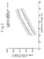
- Figure 2 is a diagram showing the range of the dispersion compensation amount, at the receiving end, that can satisfy desired transmission characteristics (amplitude attenuation of 1 dB or less, phase margin of 70% or larger) for various transmission distances.
- Figure 2 and Figure 4 given later both show the results of a computer simulation conducted considering the SPM effect of the fiber. It is shown in Figure 2 that, to cover transmission distances from 50 km to 130 km, four types of dispersion compensators are necessary as indicated by dotted lines.
- Figure 3 is a block diagram of an optical transmission system according to the present invention.
- the dispersion value of the SMF 14 is positive as in the case of Figure 1
- the chirping parameter ⁇ is set to a positive value, preferably a positive value not larger than 2, and more preferably +1.
- the required dispersion compensation amount is therefore larger than in the case of Figure 1. If the compensation amount of the dispersion compensator 22 is increased, the loss also increases, and the optical input power to the optical detector 24 decreases, resulting in receiver sensitivity degradation. If the gain of the preamplifier 20 is raised to increase the input optical power to the dispersion compensator 22 and hence the input power to the optical detector 24, waveform degradation occurs due to the SPM in the dispersion compensator 22.
- Figure 4 is a diagram showing the range of the dispersion compensation amount, at the receiving end, that can satisfy the desired transmission characteristics for various transmission distances when the chirping parameter ⁇ of the transmitter is set to +1 and a dispersion compensator having a dispersion amount of -400 ps/nm is used at the transmitting end.
- the chirping parameter ⁇ at the transmitting end is set to +1, the effect of the SPM in the fiber is alleviated, and the transmission characteristics are improved as a whole, thus expanding the range of the allowable dispersion amount.
- the dispersion compensators 22 and 26 used here can be constructed from a dispersion-compensating fiber (DCF), a fiber grating-type dispersion equalizer, a waveguide-type dispersion equalizer, a resonator-type dispersion equalizer, etc.
- DCF is constructed with a smaller core diameter and a larger core-clad refractive index difference than SMF, thereby shifting the zero dispersion wavelength to a longer wavelength to obtain negative dispersion at the signal light wavelength band (1.5 ⁇ m band).
- Figure 5 is a diagram showing the principle of a fiber grating-type dispersion equalizer.
- a grating 32 (producing periodic changes in refractive index) having progressively changing grating interval is provided inside a fiber 30.
- the light is reflected back from different positions depending on different wavelengths contained in the light. That is, different wavelengths of light are reflected back with different delay times; the reflected light is then extracted by a circulator 34 for dispersion equalization.
- a dispersion characteristic of opposite sign can be obtained by reversing the direction of the input to the fiber grating.
- FIG. 6 is a diagram showing the principle of a waveguide-type dispersion equalizer.
- a waveguide 36 is formed from silica (SiO 2 ), for example, on an Si substrate, and a phase shifter 42 is used to provide a phase difference between an upper waveguide 38 and a lower waveguide 40.
- An input optical signal is adjusted in phase by the phase shifter 42 so that the longer wavelength components mainly propagate, for example, through the lower waveguide and the shorter wavelength components propagate through the upper waveguide.
- a negative dispersion characteristic can be obtained.
- phase adjustment a dispersion characteristic of opposite sign can be obtained.
- a thin-film heater is used as the phase shifter 42.
- Figure 7 is a diagram showing the principle of a resonator-type dispersion equalizer.
- a fully reflective mirror 44 and a semi-transparent mirror 46 are placed opposite each other; when light enters from the side of the semi-transparent mirror 46, only light of a wavelength that corresponds to the mirror spacing undergoes multiple reflection between the mirrors, and resonance thus occurs. Near the resonant wavelength, light that underwent reflection a certain number of times proportional to its frequency is reflected back. By extracting the reflected light by a circulator, different delay times are given to the light of different wavelengths, thus achieving dispersion equalization.
- a dispersion characteristic of opposite sense can be obtained depending on whether a region higher or lower than the resonant frequency is used.
- the left half shows graphs when no dispersion compensation is applied at the receiving end, and the right half shows graphs when dispersion compensation of -1200 ps/nm is applied at the receiving end.
- the right half shows directly the tolerances of dispersion compensation under the condition of the receiver dispersion compensation of -1200 ps/nm, and by obtaining the value of the parameter ⁇ that maximizes the tolerance, an optimum value of the parameter ⁇ is determined. It is believed, however, that the optimum setting of the parameter ⁇ can be obtained in more a general form from the graphs in the left half part. The reason will be explained below.
- the generation of the nonlinear effects more or less calms down by the time the light travels 50 km or so, though this depends on the fiber attenuation (at distances longer than 50 km, the nonlinear effects scarcely occur because of reduced optical power in the fiber, though the influence of the nonlinear effects already generated does not vanish). Consequently, at distances longer than 50 km, the light spectrum no longer varies, and the nonlinear effects generated at that distance becomes negligible small.
- the dispersion amount given by the transmission channel at distances longer than 50 km if dispersion compensation is applied at the receiving end using a dispersion amount equal in absolute value but opposite in sign to the above dispersion amount, the waveform at the 50 km point can be restored. At this time, if the waveform at the 50 km point is good, it can be said that reception is possible.
- the transmission characteristics with no dispersion compensation at the receiver indicate that the compensation tolerance when the receiver dispersion compensation is applied becomes more relaxed as the attainable transmission distance is extended further beyond 50 km.
- graphs having wider and longer tolerance regions provide wider compensation tolerances when performing dispersion compensation at the receiving end in a longer-distance transmission system.
- the optimum value of the parameter ⁇ in the graphs in the left half is around +0.5, which coincides with the optimum value in the graphs in the right half part.
- the transmitter output that can be obtained through an optical amplifier is assumed to be about +10 to +20 dBm at the present time, so that the output varies about -4 dB to + 6 dB with respect to +14 dBm.
- the amount of frequency shift of the light source is proportional to the parameter ⁇ , and the amount of frequency shift due to the SPM of the transmission fiber depends on the transmitter output when the transmission distance is fixed. Therefore, when the two are in a complementary relationship, it is believed that the optimum value of the parameter ⁇ varies in proportion to the amount of change of the transmitter output. It is therefore predicted that the optimum value of the parameter ⁇ also varies about -4 dB to +6 dB with respect to +0.5, that is, within a range of 0.2 ⁇ ⁇ ⁇ 2.0.
- the upper limit value of the optimum parameter ⁇ is 2.
- 0 is appropriate when a case is also considered where the optical amplifier is not used and the transmitter output is low.
- the transmitter chirping parameter ⁇ is fixed to +1 in the system of Figure 3, it is preferable that ⁇ be made variable and be adjusted within the range of 0 ⁇ ⁇ ⁇ 2.
- the chirping parameter ⁇ can be varied by varying the driving voltage of the modulator.
- the allowable range of the dispersion compensation amount can be expanded.
Abstract
Description
- The present invention relates to an optical transmission system using optical fiber.
- In the field of optical transmission systems, the development of larger-capacity, longer-distance systems is under way. To increase the transmission capacity, methods of increasing the bit rate are being studied along with wavelength multiplexing techniques. On the other hand, longer transmission distances can be accomplished by introducing optical amplifiers. Optical amplifiers are being developed as post-amplifiers for increasing transmitter power, as preamplifiers for boosting receiver sensitivity by raising input power, or as in-line amplifiers for repeaters. With the introduction of optical amplifiers, the allowable level difference between fiber input and output has been increased, expanding the range of allowable fiber loss.
- On the other hand, the use of optical amplifiers has introduced a new problem of nonlinear effects because of increased optical input levels to the fiber. One is self-phase modulation (SPM), due to the optical Kerr effect (refractive index varies depending on light intensity), which causes frequency (wavelength) shifts in the rising and falling portions of a signal light pulse. In that case, even if the wavelength range of signal light before transmission is narrow, the signal light spreads out in wavelength range during transmission, and at the same time, the received waveform changes greatly because of the effect of chromatic dispersion. In other words, the upper limit of transmission optical power is determined by considering such effects.
- Further, the velocity of the light propagating through a fiber depends on the wavelength of the light (this is called the chromatic dispersion of the fiber). Accordingly, light pulses containing a range of wavelengths tend to spread out or contract in pulse width as they travel along a fiber. Therefore, in an optical transmission system, the received waveform after transmission through a fiber is distorted because of the chromatic dispersion and, depending on the degree of the distortion, transmission errors occur. Chromatic dispersion can thus limit the transmission distance.
- Previously, transmission degradation by fiber chromatic dispersion has been avoided by selecting a light source having a narrow wavelength range. However, as the bit rate increases up to 10 Gb/s, the problem of the fiber nonlinear effects arises, causing a situation where the transmission degradation cannot be avoided by simply selecting a light source having a narrow wavelength range.
- In view of this situation, it has been proposed to compensate for transmission characteristics by using transmitter prechirping as well as selecting a light source having a narrow wavelength range. Transmitter prechirping is a technique for causing chirping in light pulses in the transmitter. There are two types of chirping: blue chirping that causes the wavelength to shift to the longer wavelength side at the rising of an output pulse and to the shorter wavelength side at the falling thereof, and red chirping that causes the wavelength to shift to the shorter wavelength side at the rising of an output pulse and to the longer wavelength side at the falling thereof, and the type of chirping is selected depending on the fiber mainly used in the transmission channel. Japanese Unexamined Patent Publication No. 4-140712 describes how transmission characteristics can be improved by applying blue chirping (chirping parameter α is negative) when the fiber has positive chromatic dispersion with respect to the signal light, and red chirping (chirping parameter α is positive) when the fiber has negative chromatic dispersion. That is, when the blue chirping is combined with positive chromatic dispersion or the red chirping combined with negative chromatic dispersion, the falling portion of a light pulse travels through the fiber faster than the rising portion thereof, which has the effect of contracting the light pulse. In this case, since the fiber's dispersion value is proportional to its length, a dispersion compensator is inserted in series with the fiber to make the overall dispersion value of the transmission channel match the amount of prechirping in the transmitter.
- The type of fiber currently most popular and widely installed is the single-mode fiber (SMF) which has zero dispersion wavelength in the 1.3 µm band. This is because, in the case of a fiber with a relatively simple structure consisting of a uniform clad and core, the longest wavelength where zero dispersion can be achieved is 1.3 µm, and at longer wavelengths, zero dispersion can be achieved only by using a dispersion-shifted fiber (DSF) which is expensive and complex in structure, and also because that the 1.3 µm band, where fiber attenuation is considered low, has traditionally been used as the signal light wavelength. However, to extend transmission distance with the introduction of optical amplifiers, it becomes necessary to use signal light in the 1.5 µm band where erbium-doped fibers as optical amplifiers have gain regions and where fiber attenuation is considerably lower. If signal light at 1.5 µm is transmitted through an SMF whose zero dispersion is in the 1.3 µm band, dispersion is positive. In the prior art, therefore, it has been attempted to apply blue chirping (chirping parameter α is negative) to signal light in the transmitter, to try to improve the transmission characteristics by the combination with the positive dispersion of the fiber.
- However, as will be described in detail later, in a computer simulation carried out considering the SPM, it has been found that if the chirping parameter α is negative, there arises the problem that many types of dispersion compensators that are expensive have to be prepared in advance for a variety of the fiber lengths since the range of the dispersion compensation amount that satisfies the desired transmission characteristic is narrow.
- It is, accordingly, an object of the present invention to propose an optical transmission system that needs fewer types of dispersion compensators that have to be prepared in advance for the variety of the fiber lengths to satisfy the desired transmission characteristic.
- According to the present invention, there is provided an optical transmission system comprising: an optical fiber installed between a transmitting end and a receiving end, and having a positive dispersion value with respect to the wavelength of an optical signal to be transmitted from the transmitting end to the receiving end; a dispersion compensator connected in series to the optical fiber at the transmitting end and/or at the receiving end, and having a negative dispersion value with respect to the wavelength of the optical signal to be transmitted; and chirping means for applying positive chirping to the optical signal at the transmitting end.
- As will be described in detail later, according to the computer simulation conducted considering the SPM, when the parameter α of transmitter prechirping is positive, the range of the dispersion compensation amount that satisfies the desired transmission characteristic becomes wider than when the chirping is negative; as a result, a wider range of fiber length can be covered with fewer kinds of dispersion compensators. Since the phase modulation due to the SPM corresponds to chirping with a negative chirping parameter α, it is believed that if the transmitter chirping parameter α is positive, the effect of the SPM is alleviated and the transmission characteristic improves as a whole.
- In general, the parameter α that represents the degree of transmitter prechirping changes through the rising or falling edge areas of a waveform. In this specification, values at a
point 50% of the distance from the initial to the final level in the rising or falling transition of an optical output waveform are used and defined as typical values. -
- Figure 1 is a block diagram of an optical transmission system according to the prior art;
- Figure 2 is a graph showing the range of an allowable dispersion amount in the system of Figure 1;
- Figure 3 is a block diagram of an optical transmission system according to the present invention;
- Figure 4 is a graph showing the range of an allowable dispersion amount in the system of Figure 3;
- Figure 5 is a diagram showing the principle of a fiber grating-type dispersion equalizer;
- Figure 6 is a diagram showing the principle of a waveguide-type dispersion equalizer;
- Figure 7 is a diagram showing the principle of a resonator-type dispersion equalizer; and
- Figure 8 is a diagram showing graphs of attainable transmission distance versus transmitter dispersion compensation amount when transmitter power is +14 dBm.
- Before proceeding to the description of the present invention, we will first describe a prior art optical transmission system in which the chirping parameter α is set negative when the fiber dispersion value is positive. In Figure 1, a single-mode fiber (SMF) 14, whose zero dispersion wavelength is in the 1.3 µm band, is installed between a
transmitter 10 and areceiver 12. Thetransmitter 10 includes anoptical modulator 16 for converting an electrical signal into an optical signal, and a post-amplifier 18 for amplifying the output of theoptical modulator 16 directly in optical form for transmission into theSMF 14. The chirping parameter α in theoptical modulator 16 of thetransmitter 10 is negative, for example, -1. The chirping parameter α is defined by the following equation.
receiver 12 includes apreamplifier 20 for amplifying the optical signal output from theSMF 14 directly in optical form, adispersion compensator 22 for compensating for the overall dispersion value of the transmission channel so that the value counterbalances α = -1, and anoptical detector 24 for converting the optical signal into an electrical signal. The wavelength of the optical signal is in the 1.5 µm band which falls within the gain region of theoptical amplifiers SMF 14 is positive. Thedispersion compensator 22 is chosen to have an appropriate dispersion value that keeps the overall dispersion value constant despite the variety in the lengths of theSMF 14. - Figure 2 is a diagram showing the range of the dispersion compensation amount, at the receiving end, that can satisfy desired transmission characteristics (amplitude attenuation of 1 dB or less, phase margin of 70% or larger) for various transmission distances. Figure 2 and Figure 4 given later both show the results of a computer simulation conducted considering the SPM effect of the fiber. It is shown in Figure 2 that, to cover transmission distances from 50 km to 130 km, four types of dispersion compensators are necessary as indicated by dotted lines.
- Figure 3 is a block diagram of an optical transmission system according to the present invention. In the present invention, though the dispersion value of the
SMF 14 is positive as in the case of Figure 1, the chirping parameter α is set to a positive value, preferably a positive value not larger than 2, and more preferably +1. The required dispersion compensation amount is therefore larger than in the case of Figure 1. If the compensation amount of thedispersion compensator 22 is increased, the loss also increases, and the optical input power to theoptical detector 24 decreases, resulting in receiver sensitivity degradation. If the gain of thepreamplifier 20 is raised to increase the input optical power to thedispersion compensator 22 and hence the input power to theoptical detector 24, waveform degradation occurs due to the SPM in thedispersion compensator 22. In the optical transmission system shown in Figure 3, this problem has been overcome since adispersion compensator 26 is provided at the front end of the post-amplifier 18 at the transmitting end. In this case, it is desirable that the dispersion value of thedispersion compensator 26 at the transmitting end be fixed, and that the dispersion compensation amount that matches the length of theSMF 14 be selected at thedispersion compensator 22 at the receiving end. - Figure 4 is a diagram showing the range of the dispersion compensation amount, at the receiving end, that can satisfy the desired transmission characteristics for various transmission distances when the chirping parameter α of the transmitter is set to +1 and a dispersion compensator having a dispersion amount of -400 ps/nm is used at the transmitting end. As can be seen from the figure, by setting the chirping parameter α at the transmitting end to +1, the effect of the SPM in the fiber is alleviated, and the transmission characteristics are improved as a whole, thus expanding the range of the allowable dispersion amount.
- Accordingly, a wide range of transmission distances can be covered by only two types of dispersion compensators, as shown by dotted lines in the figure. Furthermore, it is possible to omit the
dispersion compensator 22 at the receiving end for transmission distances shorter than 50 km. - The
dispersion compensators - Figure 5 is a diagram showing the principle of a fiber grating-type dispersion equalizer. A grating 32 (producing periodic changes in refractive index) having progressively changing grating interval is provided inside a
fiber 30. When light enters the fiber, the light is reflected back from different positions depending on different wavelengths contained in the light. That is, different wavelengths of light are reflected back with different delay times; the reflected light is then extracted by acirculator 34 for dispersion equalization. A dispersion characteristic of opposite sign can be obtained by reversing the direction of the input to the fiber grating. - Figure 6 is a diagram showing the principle of a waveguide-type dispersion equalizer. A
waveguide 36 is formed from silica (SiO2), for example, on an Si substrate, and aphase shifter 42 is used to provide a phase difference between anupper waveguide 38 and alower waveguide 40. An input optical signal is adjusted in phase by thephase shifter 42 so that the longer wavelength components mainly propagate, for example, through the lower waveguide and the shorter wavelength components propagate through the upper waveguide. By propagating through a plurality of such waveguide pairs, a negative dispersion characteristic can be obtained. By phase adjustment, a dispersion characteristic of opposite sign can be obtained. A thin-film heater is used as thephase shifter 42. - Figure 7 is a diagram showing the principle of a resonator-type dispersion equalizer. A fully
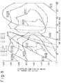
reflective mirror 44 and asemi-transparent mirror 46 are placed opposite each other; when light enters from the side of thesemi-transparent mirror 46, only light of a wavelength that corresponds to the mirror spacing undergoes multiple reflection between the mirrors, and resonance thus occurs. Near the resonant wavelength, light that underwent reflection a certain number of times proportional to its frequency is reflected back. By extracting the reflected light by a circulator, different delay times are given to the light of different wavelengths, thus achieving dispersion equalization. A dispersion characteristic of opposite sense can be obtained depending on whether a region higher or lower than the resonant frequency is used. - A description will now be given of how the value of the chirping parameter α is set in the optical transmission system of the present invention. Figure 8 shows graphs plotting the attainable transmission distance versus the transmitter dispersion compensation amount when transmitter power = +14 dBm. The left half shows graphs when no dispersion compensation is applied at the receiving end, and the right half shows graphs when dispersion compensation of -1200 ps/nm is applied at the receiving end. The right half shows directly the tolerances of dispersion compensation under the condition of the receiver dispersion compensation of -1200 ps/nm, and by obtaining the value of the parameter α that maximizes the tolerance, an optimum value of the parameter α is determined. It is believed, however, that the optimum setting of the parameter α can be obtained in more a general form from the graphs in the left half part. The reason will be explained below.
- In general, the generation of the nonlinear effects more or less calms down by the time the light travels 50 km or so, though this depends on the fiber attenuation (at distances longer than 50 km, the nonlinear effects scarcely occur because of reduced optical power in the fiber, though the influence of the nonlinear effects already generated does not vanish). Consequently, at distances longer than 50 km, the light spectrum no longer varies, and the nonlinear effects generated at that distance becomes negligible small. In other words, for the dispersion amount given by the transmission channel at distances longer than 50 km, if dispersion compensation is applied at the receiving end using a dispersion amount equal in absolute value but opposite in sign to the above dispersion amount, the waveform at the 50 km point can be restored. At this time, if the waveform at the 50 km point is good, it can be said that reception is possible.
- On the other hand, the transmission characteristics with no dispersion compensation at the receiver, indicate that the compensation tolerance when the receiver dispersion compensation is applied becomes more relaxed as the attainable transmission distance is extended further beyond 50 km. This means that, in the graphs in the left half of Figure 8, graphs having wider and longer tolerance regions provide wider compensation tolerances when performing dispersion compensation at the receiving end in a longer-distance transmission system. In fact, the optimum value of the parameter α in the graphs in the left half is around +0.5, which coincides with the optimum value in the graphs in the right half part.
- From the results of Figure 8, it is expected that the parameter α, when set at or near +0.5, gives the best result, but this value is applicable when the transmitter output is +14 dBm; it is considered that the optimum value of the parameter α will vary with transmitter output.
- The transmitter output that can be obtained through an optical amplifier is assumed to be about +10 to +20 dBm at the present time, so that the output varies about -4 dB to + 6 dB with respect to +14 dBm. Here, the amount of frequency shift of the light source is proportional to the parameter α, and the amount of frequency shift due to the SPM of the transmission fiber depends on the transmitter output when the transmission distance is fixed. Therefore, when the two are in a complementary relationship, it is believed that the optimum value of the parameter α varies in proportion to the amount of change of the transmitter output. It is therefore predicted that the optimum value of the parameter α also varies about -4 dB to +6 dB with respect to +0.5, that is, within a range of 0.2 ≤ α ≤ 2.0.
- From the above result, the upper limit value of the optimum parameter α is 2. For the lower limit value, 0 is appropriate when a case is also considered where the optical amplifier is not used and the transmitter output is low.
- Accordingly, though the transmitter chirping parameter α is fixed to +1 in the system of Figure 3, it is preferable that α be made variable and be adjusted within the range of 0 < α < 2. As is well known, when an MI external modulator or a Mach-Zehnder modulator is used as the
optical modulator 16, the chirping parameter α can be varied by varying the driving voltage of the modulator. - As described above, according to the present invention, by setting the transmitter chirping parameter to a positive value when the dispersion value of the transmission fiber is positive, the allowable range of the dispersion compensation amount can be expanded.
Claims (9)
- An optical transmission system comprising:an optical fiber installed between a transmitting end and a receiving end, and having a positive dispersion value with respect to the wavelength of an optical signal to be transmitted from the transmitting end to the receiving end;a dispersion compensator connected in series to said optical fiber at the transmitting end and/or at the receiving end, and having a negative dispersion value with respect to the wavelength of the optical signal to be transmitted; andchirping means for applying positive chirping to the optical signal at the transmitting end.
- A system according to claim 1, wherein a chirping parameter α in said chirping means is not larger than 2.
- A system according to claim 2, wherein said chirping parameter α is approximately 1.
- A system according to claim 2, wherein said chirping parameter α is variable according to the length of said optical fiber.
- A system according to claim 1, wherein said dispersion compensator includes a transmitter dispersion compensator connected fixedly at the transmitting end, and a receiver dispersion compensator connected at the receiving end, said receiver dispersion compensator being selected from among a plurality of dispersion compensators having different dispersion values according to the length of said optical fiber.
- A system according to claim 1, wherein said dispersion compensator is a dispersion-compensated fiber.
- A system according to claim 1, wherein said dispersion compensator is a fiber grating-type dispersion equalizer.
- A system according to claim 1, wherein said dispersion compensator is a waveguide-type dispersion equalizer.
- A system according to claim 1, wherein said dispersion compensator is a resonator-type dispersion equalizer.
Applications Claiming Priority (3)
| Application Number | Priority Date | Filing Date | Title |
|---|---|---|---|
| JP09870496A JP3522044B2 (en) | 1996-04-19 | 1996-04-19 | Optical transmission system |
| JP9870496 | 1996-04-19 | ||
| JP98704/96 | 1996-04-19 |
Publications (3)
| Publication Number | Publication Date |
|---|---|
| EP0802642A2 true EP0802642A2 (en) | 1997-10-22 |
| EP0802642A3 EP0802642A3 (en) | 2000-05-03 |
| EP0802642B1 EP0802642B1 (en) | 2005-09-07 |
Family
ID=14226901
Family Applications (1)
| Application Number | Title | Priority Date | Filing Date |
|---|---|---|---|
| EP96118761A Expired - Lifetime EP0802642B1 (en) | 1996-04-19 | 1996-11-22 | Optical transmission system using dispersion compensation |
Country Status (5)
| Country | Link |
|---|---|
| US (1) | US5877881A (en) |
| EP (1) | EP0802642B1 (en) |
| JP (1) | JP3522044B2 (en) |
| KR (1) | KR100249089B1 (en) |
| DE (1) | DE69635156T2 (en) |
Cited By (9)
| Publication number | Priority date | Publication date | Assignee | Title |
|---|---|---|---|---|
| US5877881A (en) * | 1996-04-19 | 1999-03-02 | Fujitsu Ltd. | Optical transmission system |
| EP0932268A2 (en) * | 1998-01-27 | 1999-07-28 | Matsushita Electric Industrial Co., Ltd. | FM signal optical transmission apparatus and FM signal optical reception apparatus |
| EP1087552A2 (en) * | 1999-09-24 | 2001-03-28 | Fujitsu Limited | Wavelength dispersion compensating method and optical transmission system |
| US6441955B1 (en) | 1998-02-27 | 2002-08-27 | Fujitsu Limited | Light wavelength-multiplexing systems |
| US6496300B2 (en) | 1998-02-27 | 2002-12-17 | Fujitsu Limited | Optical amplifier |
| US6570691B1 (en) | 1997-02-27 | 2003-05-27 | Fujitsu Limited | Optical transmission system using in-line amplifiers |
| WO2004100405A2 (en) * | 2003-05-07 | 2004-11-18 | France Telecom | Chromatic dispersion compensation in a bidirectional optical transmission system |
| US6823141B2 (en) | 1997-02-27 | 2004-11-23 | Fujitsu Limited | Optical transmission system and dispersion compensator |
| ES2364935A1 (en) * | 2010-01-29 | 2011-09-19 | Universidad Politécnica de Madrid | Method and system for the transmission of optical pulses through dispersive media. (Machine-translation by Google Translate, not legally binding) |
Families Citing this family (53)
| Publication number | Priority date | Publication date | Assignee | Title |
|---|---|---|---|---|
| FR2759516B1 (en) * | 1997-02-10 | 1999-03-26 | Alsthom Cge Alcatel | METHOD AND DEVICE FOR ONLINE REGENERATION OF A SIGNAL TRANSMITTED BY MULTIPLEX WAVELENGTH AND OPTICAL TELECOMMUNICATIONS SYSTEM INCLUDING SUCH A REGENERATION DEVICE |
| JPH1188260A (en) | 1997-09-09 | 1999-03-30 | Fujitsu Ltd | Spread compensating device of optical transmission line |
| JP3770711B2 (en) | 1997-09-11 | 2006-04-26 | 富士通株式会社 | Timing signal generating apparatus and method |
| JPH11122173A (en) * | 1997-10-20 | 1999-04-30 | Fujitsu Ltd | Detection of waveform change by wavelength dispersion, and method and device for compensation of waveform |
| US6915075B1 (en) * | 1998-02-24 | 2005-07-05 | Telefonaktiebolaget Lm Ericsson (Publ) | Protection of WDM-channels |
| JPH11266200A (en) | 1998-03-18 | 1999-09-28 | Fujitsu Ltd | Optical fiber communication method and device thereof and system used for execution of the communication method |
| EP0948151B1 (en) | 1998-03-30 | 2006-02-01 | Fujitsu Limited | Method of setting signal wavelength in optical transmission system |
| CA2344543A1 (en) * | 1998-09-21 | 2000-03-30 | Yanming Liu | Wavelength division multiplexing systems |
| JP2000236297A (en) | 1999-02-16 | 2000-08-29 | Fujitsu Ltd | Method and system for optical transmission applied with dispersion compensation |
| JP3567782B2 (en) | 1999-03-09 | 2004-09-22 | Kddi株式会社 | Dispersion compensating optical transmission line and system |
| US6430346B1 (en) | 1999-09-03 | 2002-08-06 | Corning Incorporated | Negative dispersion single mode waveguide fiber |
| CA2384431A1 (en) * | 1999-09-07 | 2001-03-15 | Jan Conradi | Positively chirped signals in optical communication systems |
| JP2001094510A (en) | 1999-09-24 | 2001-04-06 | Ddi Corp | Optical transmission system, optical transmission line, and optical transmission device |
| US6768822B1 (en) * | 2000-04-28 | 2004-07-27 | Nortel Networks Limited | Chromatic dispersion compensation |
| JP2002232355A (en) * | 2001-01-31 | 2002-08-16 | Kddi Submarine Cable Systems Inc | Optical fiber transmission line |
| JP2002280959A (en) * | 2001-03-16 | 2002-09-27 | Kddi Submarine Cable Systems Inc | Dispersion compensation light transmission line and optical transmission system |
| US7577366B2 (en) * | 2002-01-07 | 2009-08-18 | Fujitsu Limited | Selectable dispersion enhancement |
| US20030185500A1 (en) * | 2002-03-28 | 2003-10-02 | Fells Julian A. | Optical transmission systems |
| WO2003083623A2 (en) * | 2002-03-28 | 2003-10-09 | Celion Networks, Inc. | Apparatus and method for aggregation and transportation for plesiosynchronous framing oriented data formats |
| US20030185573A1 (en) * | 2002-03-28 | 2003-10-02 | Fells Julian A. | Optical transmission systems |
| AU2003220596A1 (en) * | 2002-03-29 | 2003-10-13 | Celion Networks, Inc. | Distributed terminal optical transmission system |
| US7164692B2 (en) | 2002-04-08 | 2007-01-16 | Jeffrey Lloyd Cox | Apparatus and method for transmitting 10 Gigabit Ethernet LAN signals over a transport system |
| US6965738B2 (en) * | 2002-04-16 | 2005-11-15 | Eiselt Michael H | Chromatic dispersion compensation system and method |
| JP2003318825A (en) | 2002-04-19 | 2003-11-07 | Fujitsu Ltd | Distributed compensation method in optical communication system having optical add/drop multiplexing function |
| WO2003090035A2 (en) * | 2002-04-22 | 2003-10-30 | Celion Networks, Inc. | Automated optical transport system |
| US6847678B2 (en) * | 2002-04-25 | 2005-01-25 | Raytheon Company | Adaptive air interface waveform |
| US7711271B2 (en) * | 2002-04-30 | 2010-05-04 | Eiselt Michael H | Wave division multiplexed optical transport system utilizing optical circulators to isolate an optical service channel |
| US7593637B2 (en) * | 2002-04-30 | 2009-09-22 | Angela Chiu | Optical transport system architecture for remote terminal connectivity |
| US7460296B2 (en) * | 2002-04-30 | 2008-12-02 | Pivotal Decisions Llc | Compensation for spectral power tilt from scattering |
| US8494372B2 (en) | 2002-04-30 | 2013-07-23 | Pivotal Decisions Llc | Apparatus and method for optimizing optical and electrical filtering of optical signals |
| US7206516B2 (en) | 2002-04-30 | 2007-04-17 | Pivotal Decisions Llc | Apparatus and method for measuring the dispersion of a fiber span |
| US7924496B2 (en) * | 2002-06-04 | 2011-04-12 | Pivotal Decisions Llc | Apparatus and method for Raman gain control |
| US7460745B2 (en) * | 2002-06-04 | 2008-12-02 | Pivotal Decisions Llc | Configurable dispersion compensation trimmer |
| US20040042067A1 (en) * | 2002-06-04 | 2004-03-04 | Eiselt Michael H. | Apparatus and method for duplex optical transport using a co-directional optical amplifier |
| US6920277B2 (en) | 2002-06-04 | 2005-07-19 | Marvin R. Young | Optical bypass method and architecture |
| US7603042B2 (en) * | 2002-06-04 | 2009-10-13 | Eiselt Michael H | Apparatus and method for optimum decision threshold setting |
| AU2003273529A1 (en) * | 2002-06-04 | 2003-12-19 | Celion Networks, Inc. | Flexible, dense line card architecture |
| US20050226630A1 (en) * | 2003-06-03 | 2005-10-13 | Celion Networks Inc. | Optical bypass method and architecture |
| US7440164B2 (en) * | 2002-06-04 | 2008-10-21 | Pivotal Decisions Llc | Apparatus and method for Raman gain spectral control |
| US7421207B2 (en) | 2002-12-13 | 2008-09-02 | Pivotal Decisions Llc | Single fiber duplex optical transport |
| US7656905B2 (en) | 2002-12-24 | 2010-02-02 | Samir Sheth | Apparatus and method for aggregation and transportation of gigabit ethernet and other packet based data formats |
| US7782778B2 (en) * | 2002-12-24 | 2010-08-24 | Samir Satish Sheth | Apparatus and method for fibre channel distance extension embedded within an optical transport system |
| US6898347B2 (en) * | 2003-05-30 | 2005-05-24 | Intel Corporation | Monitoring power in optical networks |
| KR101025384B1 (en) * | 2003-06-13 | 2011-03-28 | 파나소닉 주식회사 | System, device, and method for radio frequency optical transmission |
| US7254342B2 (en) * | 2003-10-29 | 2007-08-07 | Fujitsu Limited | Method and system for transmitting information in an optical communication system with low signal distortion |
| JP4872319B2 (en) * | 2005-11-18 | 2012-02-08 | 日本電気株式会社 | Optical signal transmission / reception system, optical wavelength division multiplexing transmission system, optical transmission / reception apparatus, and optical wavelength division multiplexing transmission method |
| US7266257B1 (en) * | 2006-07-12 | 2007-09-04 | Lucent Technologies Inc. | Reducing crosstalk in free-space optical communications |
| US7693425B2 (en) * | 2007-01-11 | 2010-04-06 | Fujitsu Limited | Method and system for compensating for optical dispersion in an optical signal in a hybrid optical network |
| JP5181770B2 (en) * | 2008-03-27 | 2013-04-10 | 富士通株式会社 | Optical transmission system |
| US8768168B2 (en) | 2008-09-03 | 2014-07-01 | Nec Corporation | Optical signal transmission systems, transmitters, receivers, and optical signal transmission method |
| US9778193B2 (en) * | 2013-08-22 | 2017-10-03 | Kinetic River Corp. | Methods and apparatuses for label-free particle analysis |
| CN106130644B (en) * | 2016-07-20 | 2018-04-03 | 上海交通大学 | Frequency-domain equilibrium method based on dispersion overcompensation |
| US20230084066A1 (en) * | 2021-09-14 | 2023-03-16 | Huawei Technologies Co., Ltd. | System and method for dispersion compensation in fibered optical communication paths |
Citations (1)
| Publication number | Priority date | Publication date | Assignee | Title |
|---|---|---|---|---|
| JPH04140712A (en) | 1990-10-02 | 1992-05-14 | Fujitsu Ltd | Optical transmission equipment |
Family Cites Families (15)
| Publication number | Priority date | Publication date | Assignee | Title |
|---|---|---|---|---|
| CA2011954C (en) * | 1989-03-14 | 1994-02-22 | Hiroshi Hamano | Optical modulator |
| EP0444688B1 (en) * | 1990-03-01 | 1997-10-08 | Fujitsu Limited | Optical transmitter |
| FR2681202B1 (en) * | 1991-09-06 | 1993-11-12 | Alcatel Cit | OPTICAL COMMUNICATION LINK WITH CORRECTION OF NON-LINEAR EFFECTS, AND METHOD FOR PROCESSING AN OPTICAL SIGNAL. |
| FR2685835A1 (en) * | 1991-12-31 | 1993-07-02 | France Telecom | VERY LONG DISTANCE TRANSMISSION SYSTEM ON OPTICAL FIBER COMPENSATED FOR DISTORTIONS AT RECEPTION. |
| US5361319A (en) * | 1992-02-04 | 1994-11-01 | Corning Incorporated | Dispersion compensating devices and systems |
| US5303079A (en) * | 1992-04-09 | 1994-04-12 | At&T Bell Laboratories | Tunable chirp, lightwave modulator for dispersion compensation |
| JP2760233B2 (en) * | 1992-09-29 | 1998-05-28 | 住友電気工業株式会社 | Optical communication device |
| FR2700901B1 (en) * | 1993-01-28 | 1995-02-24 | Alcatel Nv | Soliton transmission system and method. |
| JP3269713B2 (en) * | 1993-09-03 | 2002-04-02 | 株式会社日立製作所 | Optical transmission system |
| JPH08288904A (en) * | 1995-04-11 | 1996-11-01 | Nippon Telegr & Teleph Corp <Ntt> | Optical pulse transmission system |
| JP3522044B2 (en) * | 1996-04-19 | 2004-04-26 | 富士通株式会社 | Optical transmission system |
| JP2000357992A (en) * | 1999-06-16 | 2000-12-26 | Nec Corp | Optical transmission line and optical transmission system |
| JP2002164846A (en) * | 2000-11-28 | 2002-06-07 | Nec Corp | Optical transmission system |
| JP4741118B2 (en) * | 2001-08-20 | 2011-08-03 | 株式会社日立製作所 | Optical transmission system, wavelength division multiplexer, and dispersion compensation method for wavelength division multiplexing transmission system |
| JP2003348021A (en) * | 2002-05-28 | 2003-12-05 | Sumitomo Electric Ind Ltd | Optical transmitter and optical communication system |
-
1996
- 1996-04-19 JP JP09870496A patent/JP3522044B2/en not_active Expired - Lifetime
- 1996-11-20 US US08/752,516 patent/US5877881A/en not_active Expired - Lifetime
- 1996-11-22 EP EP96118761A patent/EP0802642B1/en not_active Expired - Lifetime
- 1996-11-22 DE DE69635156T patent/DE69635156T2/en not_active Expired - Lifetime
- 1996-12-13 KR KR1019960065188A patent/KR100249089B1/en not_active IP Right Cessation
Patent Citations (1)
| Publication number | Priority date | Publication date | Assignee | Title |
|---|---|---|---|---|
| JPH04140712A (en) | 1990-10-02 | 1992-05-14 | Fujitsu Ltd | Optical transmission equipment |
Cited By (17)
| Publication number | Priority date | Publication date | Assignee | Title |
|---|---|---|---|---|
| US5877881A (en) * | 1996-04-19 | 1999-03-02 | Fujitsu Ltd. | Optical transmission system |
| US6823141B2 (en) | 1997-02-27 | 2004-11-23 | Fujitsu Limited | Optical transmission system and dispersion compensator |
| US7376361B2 (en) | 1997-02-27 | 2008-05-20 | Fujitsu Limited | Optical transmission system and dispersion compensator |
| US7263296B2 (en) | 1997-02-27 | 2007-08-28 | Fujitsu Limited | Optical transmission system using in-line amplifiers |
| US7116918B2 (en) | 1997-02-27 | 2006-10-03 | Fujitsu Limited | Optical transmission system using in-line amplifiers |
| US6570691B1 (en) | 1997-02-27 | 2003-05-27 | Fujitsu Limited | Optical transmission system using in-line amplifiers |
| US7116913B2 (en) | 1997-02-27 | 2006-10-03 | Fujitsu Limited | Optical transmission system and dispersion compensator |
| EP0932268A2 (en) * | 1998-01-27 | 1999-07-28 | Matsushita Electric Industrial Co., Ltd. | FM signal optical transmission apparatus and FM signal optical reception apparatus |
| EP0932268A3 (en) * | 1998-01-27 | 2004-05-12 | Matsushita Electric Industrial Co., Ltd. | FM signal optical transmission apparatus and FM signal optical reception apparatus |
| US6496300B2 (en) | 1998-02-27 | 2002-12-17 | Fujitsu Limited | Optical amplifier |
| US6919987B2 (en) | 1998-02-27 | 2005-07-19 | Fujitsu Limited | Light wavelength-multiplexing systems |
| US6441955B1 (en) | 1998-02-27 | 2002-08-27 | Fujitsu Limited | Light wavelength-multiplexing systems |
| EP1087552A3 (en) * | 1999-09-24 | 2003-05-07 | Fujitsu Limited | Wavelength dispersion compensating method and optical transmission system |
| EP1087552A2 (en) * | 1999-09-24 | 2001-03-28 | Fujitsu Limited | Wavelength dispersion compensating method and optical transmission system |
| WO2004100405A3 (en) * | 2003-05-07 | 2005-05-19 | France Telecom | Chromatic dispersion compensation in a bidirectional optical transmission system |
| WO2004100405A2 (en) * | 2003-05-07 | 2004-11-18 | France Telecom | Chromatic dispersion compensation in a bidirectional optical transmission system |
| ES2364935A1 (en) * | 2010-01-29 | 2011-09-19 | Universidad Politécnica de Madrid | Method and system for the transmission of optical pulses through dispersive media. (Machine-translation by Google Translate, not legally binding) |
Also Published As
| Publication number | Publication date |
|---|---|
| KR100249089B1 (en) | 2000-03-15 |
| KR970071036A (en) | 1997-11-07 |
| US5877881A (en) | 1999-03-02 |
| JPH09284218A (en) | 1997-10-31 |
| EP0802642A3 (en) | 2000-05-03 |
| JP3522044B2 (en) | 2004-04-26 |
| DE69635156D1 (en) | 2005-10-13 |
| DE69635156T2 (en) | 2006-06-29 |
| EP0802642B1 (en) | 2005-09-07 |
Similar Documents
| Publication | Publication Date | Title |
|---|---|---|
| EP0802642B1 (en) | Optical transmission system using dispersion compensation | |
| US6418256B1 (en) | High order spatial mode optical fiber | |
| EP0626768B1 (en) | High capacity optical fiber network and fiber | |
| EP0732819A2 (en) | Chromatic dispersion compensator and chromatic dispersion compensating optical communication system | |
| JPH05265060A (en) | Superlong distance digital transmission equipment using optical fiber for compensating distortion of receiving terminal | |
| JPH098730A (en) | Multichannel optical fiber communication system | |
| JPH0923187A (en) | Optical transmission system | |
| JP2002533774A (en) | Optical system and method with low loss and nonlinear effects | |
| US6256440B1 (en) | Dispersion-shifted optical fiber | |
| US6304691B1 (en) | Wavelength division multiplexed optical communication system having reduced short wavelength loss | |
| JP4519238B2 (en) | Optical fiber transmission system, optical fiber transmission line, and optical fiber transmission method | |
| WO2000051269A9 (en) | High order spatial mode optical fiber | |
| WO2004034613A2 (en) | Devices and methods for dynamic dispersion compensation | |
| US6360045B1 (en) | High order spatial mode transmission system | |
| US6526208B1 (en) | Dispersion managed fiber optic cable and system | |
| US7218807B2 (en) | Optical transmission system using an optical phase conjugation device | |
| US7079737B1 (en) | Devices and methods for dynamic dispersion compensation | |
| EP1576747B1 (en) | Optical transmission system using an optical phase conjugation device | |
| US5677780A (en) | Method of improving the electrical eye margin of an optical fiber transmission system having single mode and dispersion compensating fiber segments | |
| US6462849B1 (en) | Optimizing launch points for dispersion-managed solitons | |
| EP0850515A2 (en) | Optical pulse propagation | |
| EP1488550B1 (en) | Optical transmission system using an optical phase conjugation device | |
| JP3508898B2 (en) | Optical soliton communication transmission line | |
| Hamidine et al. | Dispersion and dispersion slope compensation impact on high channel bit rate optical signal transmission degradation | |
| WO1999013588A2 (en) | Optimizing launch points for dispersion-managed solitons |
Legal Events
| Date | Code | Title | Description |
|---|---|---|---|
| PUAI | Public reference made under article 153(3) epc to a published international application that has entered the european phase |
Free format text: ORIGINAL CODE: 0009012 |
|
| AK | Designated contracting states |
Kind code of ref document: A2 Designated state(s): DE FR GB |
|
| PUAL | Search report despatched |
Free format text: ORIGINAL CODE: 0009013 |
|
| AK | Designated contracting states |
Kind code of ref document: A3 Designated state(s): DE FR GB |
|
| 17P | Request for examination filed |
Effective date: 20000705 |
|
| 17Q | First examination report despatched |
Effective date: 20040216 |
|
| GRAP | Despatch of communication of intention to grant a patent |
Free format text: ORIGINAL CODE: EPIDOSNIGR1 |
|
| GRAS | Grant fee paid |
Free format text: ORIGINAL CODE: EPIDOSNIGR3 |
|
| GRAA | (expected) grant |
Free format text: ORIGINAL CODE: 0009210 |
|
| AK | Designated contracting states |
Kind code of ref document: B1 Designated state(s): DE FR GB |
|
| REG | Reference to a national code |
Ref country code: GB Ref legal event code: FG4D |
|
| REF | Corresponds to: |
Ref document number: 69635156 Country of ref document: DE Date of ref document: 20051013 Kind code of ref document: P |
|
| ET | Fr: translation filed | ||
| PLBE | No opposition filed within time limit |
Free format text: ORIGINAL CODE: 0009261 |
|
| STAA | Information on the status of an ep patent application or granted ep patent |
Free format text: STATUS: NO OPPOSITION FILED WITHIN TIME LIMIT |
|
| 26N | No opposition filed |
Effective date: 20060608 |
|
| PGFP | Annual fee paid to national office [announced via postgrant information from national office to epo] |
Ref country code: DE Payment date: 20141118 Year of fee payment: 19 Ref country code: GB Payment date: 20141119 Year of fee payment: 19 Ref country code: FR Payment date: 20141110 Year of fee payment: 19 |
|
| REG | Reference to a national code |
Ref country code: DE Ref legal event code: R119 Ref document number: 69635156 Country of ref document: DE |
|
| GBPC | Gb: european patent ceased through non-payment of renewal fee |
Effective date: 20151122 |
|
| REG | Reference to a national code |
Ref country code: FR Ref legal event code: ST Effective date: 20160729 |
|
| PG25 | Lapsed in a contracting state [announced via postgrant information from national office to epo] |
Ref country code: GB Free format text: LAPSE BECAUSE OF NON-PAYMENT OF DUE FEES Effective date: 20151122 Ref country code: DE Free format text: LAPSE BECAUSE OF NON-PAYMENT OF DUE FEES Effective date: 20160601 |
|
| PG25 | Lapsed in a contracting state [announced via postgrant information from national office to epo] |
Ref country code: FR Free format text: LAPSE BECAUSE OF NON-PAYMENT OF DUE FEES Effective date: 20151130 |