EP0802827B1 - Spray nozzle - Google Patents
Spray nozzle Download PDFInfo
- Publication number
- EP0802827B1 EP0802827B1 EP96901030A EP96901030A EP0802827B1 EP 0802827 B1 EP0802827 B1 EP 0802827B1 EP 96901030 A EP96901030 A EP 96901030A EP 96901030 A EP96901030 A EP 96901030A EP 0802827 B1 EP0802827 B1 EP 0802827B1
- Authority
- EP
- European Patent Office
- Prior art keywords
- nozzle
- atomizer
- core
- spray
- spray nozzle
- Prior art date
- Legal status (The legal status is an assumption and is not a legal conclusion. Google has not performed a legal analysis and makes no representation as to the accuracy of the status listed.)
- Expired - Lifetime
Links
Images

Classifications
-
- B—PERFORMING OPERATIONS; TRANSPORTING
- B65—CONVEYING; PACKING; STORING; HANDLING THIN OR FILAMENTARY MATERIAL
- B65D—CONTAINERS FOR STORAGE OR TRANSPORT OF ARTICLES OR MATERIALS, e.g. BAGS, BARRELS, BOTTLES, BOXES, CANS, CARTONS, CRATES, DRUMS, JARS, TANKS, HOPPERS, FORWARDING CONTAINERS; ACCESSORIES, CLOSURES, OR FITTINGS THEREFOR; PACKAGING ELEMENTS; PACKAGES
- B65D83/00—Containers or packages with special means for dispensing contents
- B65D83/14—Containers or packages with special means for dispensing contents for delivery of liquid or semi-liquid contents by internal gaseous pressure, i.e. aerosol containers comprising propellant for a product delivered by a propellant
- B65D83/16—Containers or packages with special means for dispensing contents for delivery of liquid or semi-liquid contents by internal gaseous pressure, i.e. aerosol containers comprising propellant for a product delivered by a propellant characterised by the actuating means
- B65D83/20—Containers or packages with special means for dispensing contents for delivery of liquid or semi-liquid contents by internal gaseous pressure, i.e. aerosol containers comprising propellant for a product delivered by a propellant characterised by the actuating means operated by manual action, e.g. button-type actuator or actuator caps
-
- B—PERFORMING OPERATIONS; TRANSPORTING
- B05—SPRAYING OR ATOMISING IN GENERAL; APPLYING FLUENT MATERIALS TO SURFACES, IN GENERAL
- B05B—SPRAYING APPARATUS; ATOMISING APPARATUS; NOZZLES
- B05B1/00—Nozzles, spray heads or other outlets, with or without auxiliary devices such as valves, heating means
- B05B1/34—Nozzles, spray heads or other outlets, with or without auxiliary devices such as valves, heating means designed to influence the nature of flow of the liquid or other fluent material, e.g. to produce swirl
- B05B1/3405—Nozzles, spray heads or other outlets, with or without auxiliary devices such as valves, heating means designed to influence the nature of flow of the liquid or other fluent material, e.g. to produce swirl to produce swirl
- B05B1/341—Nozzles, spray heads or other outlets, with or without auxiliary devices such as valves, heating means designed to influence the nature of flow of the liquid or other fluent material, e.g. to produce swirl to produce swirl before discharging the liquid or other fluent material, e.g. in a swirl chamber upstream the spray outlet
- B05B1/3421—Nozzles, spray heads or other outlets, with or without auxiliary devices such as valves, heating means designed to influence the nature of flow of the liquid or other fluent material, e.g. to produce swirl to produce swirl before discharging the liquid or other fluent material, e.g. in a swirl chamber upstream the spray outlet with channels emerging substantially tangentially in the swirl chamber
- B05B1/3431—Nozzles, spray heads or other outlets, with or without auxiliary devices such as valves, heating means designed to influence the nature of flow of the liquid or other fluent material, e.g. to produce swirl to produce swirl before discharging the liquid or other fluent material, e.g. in a swirl chamber upstream the spray outlet with channels emerging substantially tangentially in the swirl chamber the channels being formed at the interface of cooperating elements, e.g. by means of grooves
- B05B1/3436—Nozzles, spray heads or other outlets, with or without auxiliary devices such as valves, heating means designed to influence the nature of flow of the liquid or other fluent material, e.g. to produce swirl to produce swirl before discharging the liquid or other fluent material, e.g. in a swirl chamber upstream the spray outlet with channels emerging substantially tangentially in the swirl chamber the channels being formed at the interface of cooperating elements, e.g. by means of grooves the interface being a plane perpendicular to the outlet axis
Definitions
- the present invention relates to a spray nozzle intended to be mounted on a outlet channel of a fluid dispenser device for dividing said product fluid in fine droplets.
- Certain fluid products such as perfumes for example are preferably distributed in vaporized or sprayed form to increase the dispersion of the product and avoid too localized application.
- a spray mounted on the outlet channel of the dispensing device which in general is a pump or valve.
- the spray nozzles are most often integrated into the push button of the pump or valve, in which case they move vertically when the device. They can also be integral with a part of the device which remains static upon actuation.
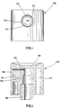
- FIG. 1 is a front view of the nozzle, then that the nozzle has been removed to reveal the interior of the nozzle.
- the push button 100 is in the form of a small cylinder closed at its upper end by a curved ergonomic surface 118 adapted to the application of a finger.
- the cylinder is made with a cylindrical housing 110 which is partially filled by a core 111 of shape cylindrical which extends horizontally to the center of the housing 110.
- An annular space 114 is thus created between the cylindrical internal wall of the housing 110 and the core 111.
- a window 112 communicates the annular space 114 with an internal channel 117, as can be see Figures 2 and 3.
- the internal channel 117 receives the end of a hollow rod actuation 103.
- the core 111 has a smooth front surface 119.
- a nozzle 102 is fitted with force on the core 111, as visible in FIG. 3.
- the nozzle 102 is presented under the shape of a small bucket whose bottom is pierced with an orifice 121, called spray.
- the sprinkler therefore comprises a bottom and an annular skirt 122 which is forcibly engaged in the annular space 114 (fig. 1).
- the internal wall of the skirt is made with three channels supply 113 distributed angularly and extending over the entire height of the skirt 122.
- the skirt does not come into contact with the bottom of the annular space 114 so that there is a annular passage 115 which communicates the window with the supply channels 113 (fig. 3).
- the bottom of the nozzle 102 has a structured internal wall 129 in which are formed three swirl channels 125 and a swirl 124 centered on the spray orifice 121 (fig. 4).
- the canals of swirl and the swirl chamber are completed by the waterproof application of the internal surface 129 of the nozzle against the smooth front surface 119 of the core. Canals are thus isolated from each other.
- the three channels of swirl 125 are each in communication with one of the three supply channels 113. The fluid distributed by the pump or the valve therefore flows through the rod hollow 103, the internal channel 117, the window 112, the annular passage 115, the three channels feed, the three swirl channels, the swirl chamber and the spray orifice.
- the height of the nozzle is directly related to the height of the nozzle, and therefore its structure.
- the present invention aims to reduce the height of the nozzle, which allows reduce the total height of the dispensing device.
- this problem is solved by providing advantageously that the swirl channels communicate with the outlet channel of the spraying device via several supply conduits symmetrical, to each of the swirl channels corresponding to a conduit feed, so that all of the swirl channels are supplied with product fluid evenly. This ensures that the fluid flow path is identical for each of the swirl channels.
- a reduction in height is possible, while ensuring a perfectly balanced supply of the swirl channels.
- a reduced size nozzle is produced, having in addition an improved dynamic behavior.
- the contact surface of the fluid on the nozzle is also reduced.
- the nozzle no longer needs to be fitted with as great a force as in the prior art.
- the nozzle must resist a pressure of 30.10 5 Pa, while for a nozzle according to the invention, a pressure of 12 to 15.10 5 Pa is sufficient. It is therefore simpler to hang a nozzle according to the invention, since the attachment means do not need to withstand high pressures.
- the spraying of the fluid product is obtained thanks to the vortex which is created in the swirl chamber, due to the fact that the swirl channels open out in the room non-radially.
- the fluid product therefore undergoes a movement vortex in the chamber which generates centrifugal acceleration before exiting at through the spray hole which is perfectly centered on the vortex eye.
- the product emitted fluid is then distributed in the atmosphere with a conical dispersion.
- the spray orifice is perfectly centered on the eye of the vortex, otherwise the fluid would be distributed with large droplets, because it is in the eye of the vortex that the acceleration is strongest.
- the nozzle must therefore be molded with great precision, so that the swirl chamber is exactly centered on the spray hole.
- the swirl channels must also be very precisely molded, as well as the feed channels. The sprinkler therefore constitutes a high precision part.
- the nozzle fitting on the core must also be performed with great precision.
- said swirl channels and at least part of the swirl chamber are formed in a front wall of the core, the nozzle having an inner wall in tight contact with said front wall of the core to isolate the channels from swirling from each other.
- the nozzle forms part of the chamber swirling.
- the swirl chamber therefore consists of two parts, one formed in the front wall of the core and the other in the nozzle.
- the part formed in the nozzle corresponds to that where the eye of the vortex is formed.
- the nozzle has a symmetry with respect to a plane extending perpendicular to the axis passing through the spray orifice, so that the nozzle has two identical faces thus making it reversible.
- the nozzle then simply presents itself in the form of an oblong patch pierced with a central hole formed between two recesses symmetrical cylinders which define the two parts of the swirl chamber.
- the nozzle does not include an annular skirt as is the case in the prior art. he therefore follows a considerable simplification of the nozzle which offers advantages to different levels.
- the nozzle is reversible due to its symmetry, which simplifies the orientation of the nozzle when it is mounted on the core.
- the sprinkler requires less of material due to its small size and the absence of an annular skirt.
- it is easier to mold with a mold in two identical parts.
- the chamber parts symmetrical with the centered spray hole are easier to achieve because the spindle required for molding is shorter, which increases its accuracy. So we can mold a nozzle according to the invention with great precision using a more spindle easy to manipulate.
- the nozzle is received hermetically in a housing containing the supply conduits and the core, said nozzle being provided on its periphery of contact with said housing of a sealing bead which bites into the constituent material said accommodation.
- the sprinkler is therefore forcibly engaged in the housing and is held there by a sort of harpoon effect.
- said nozzle has a peripheral penetration chamfer to facilitate mounting of said nozzle in said housing. During assembly, the nozzle does not need to be brought in perfectly centered towards the housing. If not, the penetration chamfers will refocus automatically the nozzle on its housing.
- the output channel of the spray has a crenellated free end which communicates with the conduits nozzle supply.
- the nozzle can be an integral part of a push button mounted on a rod hollow actuator defining the outlet channel.
- the push button is designated in this example by the numeric reference 1. It is intended to be fitted on an outlet channel such as a rod hollow actuation 3 of a fluid dispenser device such as a pump or a valve.
- the spray nozzle produced according to an embodiment of the invention is integrated into push-button 1, as is customary.
- the spray nozzle which will now be described in detail can just as easily be integrated in another element of a spraying device incorporating an outlet channel.
- the invention relates to the very structure of the nozzle and not to its arrangement with respect to the distribution device.
- the embodiment chosen to illustrate the invention puts however the spray nozzle used in a generally shaped push button classic.
- Push button 1 is in the form of a small hollow cylinder closed at its upper end by a surface 18 adapted to receive pressure exerted by a finger for example.
- the push button 1 comprises on its cylindrical part an oblong housing 10 in which is received a nozzle of corresponding shape.
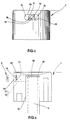
- Figures 5 and 6 show the push button with the nozzle removed to reveal the inside of the oblong housing 10.
- This contains a core 11 which partially fills said housing 10 and two conduits 12 and 13 so-called power supplies which sink into the push button on either side of the core extending parallel in a horizontal plane, when the surface 18 is directed towards the top, as shown in Figures 5 and 6. While conventionally, the core is surrounded by an annular passage (see 114, fig.
- the core no longer constitutes a protruding lug surrounded by an annular space, but is directly connected by its parts higher and lower than the constituent mass of the push button 1, as visible on the Figures 5 and 6.
- the core no longer projects freely towards the front, but literally part of the push button.
- the nucleus constitutes a partition wall for the two supply conduits 12, 13.
- the core 11 extends radially inward of the push button and ends just before it opens into the internal channel 17 in which the actuating rod 3 is mounted.
- the latter has an open upper end 30 which is produced with a notch whose tips are in abutment against the upper wall of the internal channel which defines also a part of the pushing surface 18. Thanks to this notch, the fluid product can flow out of the actuating rod 3 without the need to provide a any means at the top wall of the internal channel 17 to prevent the open upper end 30 of the rod 3 is not in tight contact with the wall upper of the internal channel 17, which would prevent the flow of the fluid product. We win thus in height since the actuating rod 3 penetrates as much as possible into the push button 1.
- the two supply ducts 12, 13 of the invention have much higher sections. Also, like the conduits supply connect the internal channel 17 without performing a throttling, there is no pressure drop at this level, whereas in a conventional nozzle of the prior art, the window 112 (fig. 1) was a cause of a large pressure drop just before the canals supply 113.
- the swirl channels can be supplied with fluid optimally without creating a pressure drop before their Entrance.
- the core 11 has a front end wall 19 which is slightly depressed in the housing 10 of about 1 millimeter.
- This wall 19 is not flat, but incorporates, a swirl chamber part 14 and two swirl channels 15 and 16 which open with one of their ends in the swirl chamber 14 of non-radial way and with the other of their ends respectively in each of supply ducts, as seen in Figure 5. While it is normally usual to mold the chamber and the swirl channels in the nozzle, according to the present invention, these are molded into the front wall of the core 11.
- the pin used in the mold adapted to mold such a nozzle is of a relatively simple design.
- this pin comprises two branches corresponding to the supply conduits 12 and 13 connected together by a bridge in which the negative of the chamber and channels of swirling is machined, for example by electro-erosion.
- the branches of the brooch extend into the internal channel 17 which is formed by another cylindrical pin the upper end of which is inserted between the two branches of the core pin.
- the core has a substantially trapezoidal shape to favor internal channel pin engagement and disengagement in and out respectively branches of the core pin.
- the branches of the core spindle engage in the internal channel 17.
- the part of the nozzle spraying which is an integral part of the push button is therefore very simple to carry out with only two extremely simple pins.
- the swirl channels being given that they each communicate with a supply duct, are perfectly symmetrical with respect to the swirl chamber and will therefore be supplied with fluid identically. This is a particularly advantageous characteristic, because it ensures perfect vortex formation in the vortex chamber.
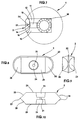
- the nozzle 2 corresponding to the shape of the housing 10 in which it is received, is oblong, in this case wider than high. As an example, the nozzle presents a width of about 3 millimeters for a height of about 1 millimeter. These magnitudes cannot be limiting. Compared to a conventional nozzle of the prior art, there is a gain almost 2 millimeters in height which affects the height of push button 1.
- the nozzle is in the form of an oblong grain pierced with a central orifice 21, called spray.
- the spray orifice is formed between two symmetrical recesses substantially cylindrical which it communicates and which each define a part of swirl chamber 24 complementary to the chamber part 14 formed in the core 11.
- the nozzle is symmetrical by with respect to a vertical plane perpendicular to the axis passing through the center of the orifice spraying and in which is contained the longitudinal axis of the nozzle.
- This plan therefore passes between the two parts of the swirl chamber 24, and thus makes the nozzle reversible, which explains the duplication of the complementary part 24 of the swirl. Only one of the complementary parts of room 24 will fulfill the function for which it is intended, the other then serving only as exhaust nozzle.
- This reversibility of the nozzle eliminates an operation prior orientation of the nozzle before mounting on the push button. This allows to eliminate a baffle in the bowl used for the orientation of the nozzle in the chain mounting.
- the technique preferably used is force engagement with material interference.
- the nozzle is provided on its outer oblong periphery of a sealing bead 22 which gives the nozzle a oversizing in relation to the housing 10.
- a material harder than that of the push button for example POM (polyoxymethylene) for the sprinkler and polyethylene for the push button
- cord 22 will bite into the internal wall of the housing by deformation of material.
- the nozzle is formed with penetration chamfers which allow to automatically center the nozzle on its housing.
- the nozzle is in contact by one of its faces 29, incorporating a part of swirl chamber 24, with the front wall 19 of the core incorporating the chamber 14 and the channels 15, 16.
- the contact between the face 29 and the front wall 19 is sealed, so that the swirl channels are isolated from each other others between the complete swirl chamber 14, 24 and the respective conduits supply 12, 13.
- the front wall 19 of the core extends vertically when the nozzle is straight outfit.
- the nozzle would be fitted obliquely, so that the spray would be sprayed with an angle of diffusion from the horizontal.
- the fluid tank must remain oriented vertically, while the product jet spray must be directed upwards with a predetermined diffusion angle.
- the swirl chamber which is traditionally formed only in the nozzle consists here of two parts respectively formed one in the core and the other in the sprinkler. This division into two parts does not cause any complications in terms of vortex formation in the vortex chamber, as it has been noticed that the eye of the vortex always forms in the center of the spray orifice, provided that the part of sprinkler chamber is well centered. In other words, the eye of the vortex is formed in the orifice even if the two chamber parts are not perfectly aligned. The precision during molding must therefore be carried on the nozzle. Now it is much easier to mold a flat nozzle (without annular skirt 122; fig. 3) which is moreover perfectly symmetrical.
- the necessary mold only consists of two identical parts each incorporating a spindle for forming the swirl chamber parts 24 and the spray orifice.
- the two pins required are extremely short and it is known that the precision of molding is all the greater the shorter the pins. Therefore, increased molding accuracy is achieved without using more pins precise.
- the nozzle is easily moldable with a minimum of material, using a very simple in two parts. It is also easy to mount on the push button due to its reversibility and the decrease in pressure on it.
Description
La présente invention a trait à une buse de pulvérisation destinée à être montée sur un canal de sortie d'un dispositif de distribution de produit fluide pour diviser ledit produit fluide en fines gouttelettes. Certains produits fluides tels que les parfums par exemple, sont de préférence distribués sous forme vaporisée ou pulvérisée pour augmenter la dispersion du produit et éviter une application trop localisée. Pour ce faire, on utilise une buse de pulvérisation montée sur le canal de sortie du dispositif de distribution qui en général est une pompe ou une valve.The present invention relates to a spray nozzle intended to be mounted on a outlet channel of a fluid dispenser device for dividing said product fluid in fine droplets. Certain fluid products such as perfumes for example are preferably distributed in vaporized or sprayed form to increase the dispersion of the product and avoid too localized application. To do this, we use a spray mounted on the outlet channel of the dispensing device which in general is a pump or valve.
Les buses de pulvérisation sont le plus souvent intégrées dans le bouton-poussoir de la pompe ou de la valve, auquel cas elles se déplacent verticalement lors de l'actionnement du dispositif. Elles peuvent également être solidaires d'une pièce du dispositif qui reste statique lors de l'actionnement.The spray nozzles are most often integrated into the push button of the pump or valve, in which case they move vertically when the device. They can also be integral with a part of the device which remains static upon actuation.
Les figures 1 à 4 illustrent une buse de pulvérisation classique de l'art antérieur
intégrée dans un bouton-poussoir 100. La figure 1 est une une vue de face de la buse, alors
que le gicleur a été retiré pour laisser apparaítre l'intérieur de la buse. Le bouton-poussoir
100 se présente sous la forme d'un petit cylindre fermé à son extrémité supérieure par une
surface ergonomique incurvée 118 adaptée à l'application d'un doigt. Le cylindre est réalisé
avec un logement cylindrique 110 qui est partiellement rempli par un noyau 111 de forme
cylindrique qui s'étend horizontalement au centre du logement 110. Un espace annulaire 114
est ainsi crée entre la paroi interne cylindrique du logement 110 et le noyau 111. Une fenêtre
112 fait communiquer l'espace annulaire 114 avec un canal interne 117, comme on peut le
voir sur les figures 2 et 3. Le canal interne 117 reçoit l'extrémité d'une tige creuse
d'actionnement 103.Figures 1 to 4 illustrate a conventional spray nozzle of the prior art
integrated in a
Le noyau 111 présente une surface frontale lisse 119. Un gicleur 102 est emmanché de
force sur le noyau 111, comme visible sur la figure 3. Le gicleur 102 se présente sous la
forme d'un petit godet dont le fond est percé d'un orifice 121, dit de pulvérisation. Le
gicleur comprend donc un fond et une jupe annulaire 122 qui est engagée de force dans
l'espace annulaire 114 (fig. 1). La paroi interne de la jupe est réalisée avec trois canaux
d'alimentation 113 répartis angulairement et s'étendant sur toute la hauteur de la jupe 122. La
jupe ne vient pas au contact du fond de l'espace annulaire 114 de sorte qu'il existe un
passage annulaire 115 qui fait communiquer la fenêtre avec les canaux d'alimentation 113
(fig. 3). D'autre part, le fond du gicleur 102 présente une paroi interne structurée 129 dans
laquelle sont formées trois canaux de tourbillonnement 125 et une chambre de
tourbillonnement 124 centrée sur l'orifice de pulvérisation 121 (fig. 4). Les canaux de
tourbillonnement et la chambre de tourbillonnement sont complétés par l'application étanche
de la surface interne 129 du gicleur contre la surface frontale lisse 119 du noyau. Les canaux
de tourbillonnement sont ainsi isolés les uns des autres. Les trois canaux de
tourbillonnement 125 sont chacun en communication avec un des trois canaux d'alimentation
113. Le produit fluide distribué par la pompe ou la valve s'écoule donc à travers la tige
creuse 103, le canal interne 117, la fenêtre 112, le passage annulaire 115, les trois canaux
d'alimentation, les trois canaux de tourbillonnement, la chambre de tourbillonnement et
l'orifice de pulvérisation.The
Dans cette buse de l'art antérieur, tout comme dans celles divulguées dans les documents FR-2 325 434 et DE-3 314 020, la hauteur de la buse est directement liée à la hauteur du gicleur, et par conséquent à sa structure.In this nozzle of the prior art, as in those disclosed in the documents FR-2 325 434 and DE-3 314 020, the height of the nozzle is directly related to the height of the nozzle, and therefore its structure.
La présente invention a pour but de réduire la hauteur de la buse, ce qui permet de réduire la hauteur totale du dispositif de distribution.The present invention aims to reduce the height of the nozzle, which allows reduce the total height of the dispensing device.
Pour ce faire, la présente invention a pour but une buse de pulvérisation destinée à être montée sur un canal de sortie d'un dispositif de distribution de produit fluide pour diviser ledit produit fluide en fines gouttelettes, ladite buse comprenant un noyau et un gicleur définissant ensemble : reçu hermétiquement dans un logement de ladite buse, lesdits noyau et gicleur
- une chambre de tourbillonnement qui communique avec l'extérieur par l'intermédiaire d'un orifice de pulvérisation formé dans ledit gicleur, et
- plusieurs canaux de tourbillonnement qui débouchent dans la chambre de tourbillonnement de façon non radiale,
- a swirl chamber which communicates with the outside via a spray orifice formed in said nozzle, and
- several swirl channels which open into the swirl chamber in a non-radial manner,
Cette forme de réalisation a pour résultat de diminuer la hauteur de la buse : alors qu'une buse classique s'inscrit dans un cercle comme on a pu le voir en référence à la figure 1, la buse selon l'invention s'inscrit dans le même cercle, mais uniquement avec son grand axe longitudinal couché. Par conséquent, la buse est beaucoup moins haute qu'une buse classique, ce qui permet de réduire la hauteur de la pièce dans laquelle elle est formée ou intégrée, telle qu'un bouton-poussoir.This embodiment results in reducing the height of the nozzle: then that a classic nozzle fits in a circle as we could see with reference to the figure 1, the nozzle according to the invention is in the same circle, but only with its large lying longitudinal axis. Therefore, the nozzle is much lower than a nozzle classic, which reduces the height of the room in which it is formed or integrated, such as a push button.
Un autre problème des buses de pulvérisation de l'art antérieur réside dans le fait que
les canaux d'alimentation et de tourbillonnement sont alimentés par une fenêtre unique 112.
Or, la disposition angulaire des canaux d'alimentation et de tourbillonnement est définie lors
du montage du gicleur qui n'est pas orienté angulairement, de sorte qu'un canal
d'alimentation et de tourbillonnement pourra par exemple être positionné juste au droit de la
fenêtre et ainsi être privilégié par rapport aux deux autres. Il s'ensuit une mauvaise
répartition du produit fluide issu de la fenêtre dans les différents canaux. Cet inconvénient
est inévitable étant donné qu'il est impossible de trouver une configuration qui mette les trois
canaux d'alimentation et de tourbillonnement dans une relation d'écoulement identique par
rapport à la fenêtre. Cette mauvaise répartition de l'écoulement a pour effet une malformation
du vortex au niveau de la chambre de tourbillonnement ce qui a pour conséquence une
mauvaise qualité de pulvérisation. Selon l'invention, ce problème est résolu en prévoyant
avantageusement que les canaux de tourbillonnement communiquent avec le canal de sortie
du dispositif de pulvérisation par l'intermédiaire de plusieurs conduits d'alimentation
symétriques, à chacun des canaux de tourbillonnement correspondant un conduit
d'alimentation, de sorte que tous les canaux de tourbillonnement sont alimentés en produit
fluide de manière égale. On assure ainsi que le trajet d'écoulement du fluide est identique
pour chacun des canaux de tourbillonnement.Another problem with prior art spray nozzles is that
the supply and swirl channels are supplied by a
De préférence, les conduits d'alimentation sont au nombre de deux, s'étendant de part et d'autre du noyau dans un plan horizontal.Preferably, there are two supply conduits, extending from one side and other of the nucleus in a horizontal plane.
Une diminution de hauteur est possible, tout en assurant une alimentation parfaitement équilibrée des canaux de tourbillonnement. Ainsi, une buse de taille réduite est réalisée, ayant de surcroít un comportement dynamique amélioré. De plus, comme la taille du gicleur est réduite, la surface d'appui du produit fluide sur le gicleur est également réduite. Concrètement, le gicleur n'a plus besoin d'être emmanché avec une force aussi importante que dans l'art antérieur. Par exemple, pour une buse classique, le gicleur doit résister à une pression de 30.105 Pa, alors que pour une buse selon l'invention, une pression de 12 à 15.105 Pa suffit. Il est donc plus simple d'accrocher un gicleur selon l'invention, puisque les moyens d'accrochage n'ont pas besoin de résister à de fortes pressions.A reduction in height is possible, while ensuring a perfectly balanced supply of the swirl channels. Thus, a reduced size nozzle is produced, having in addition an improved dynamic behavior. In addition, as the size of the nozzle is reduced, the contact surface of the fluid on the nozzle is also reduced. Concretely, the nozzle no longer needs to be fitted with as great a force as in the prior art. For example, for a conventional nozzle, the nozzle must resist a pressure of 30.10 5 Pa, while for a nozzle according to the invention, a pressure of 12 to 15.10 5 Pa is sufficient. It is therefore simpler to hang a nozzle according to the invention, since the attachment means do not need to withstand high pressures.
D'autre part, la pulvérisation du produit fluide est obtenue grâce au vortex qui se crée dans la chambre de tourbillonnement, du fait que les canaux de tourbillonnement débouchent dans la chambre de manière non radiale. Le produit fluide subit donc un mouvement tourbillonnaire dans la chambre qui génère une accélération centrifuge avant de sortir au travers de l'orifice de pulvérisation qui est parfaitement centré sur l'oeil de vortex. Le produit fluide émis est alors distribué dans l'atmosphère avec un dispersion conique.On the other hand, the spraying of the fluid product is obtained thanks to the vortex which is created in the swirl chamber, due to the fact that the swirl channels open out in the room non-radially. The fluid product therefore undergoes a movement vortex in the chamber which generates centrifugal acceleration before exiting at through the spray hole which is perfectly centered on the vortex eye. The product emitted fluid is then distributed in the atmosphere with a conical dispersion.
Il est essentiel que l'orifice de pulvérisation soit parfaitement centré sur l'oeil du vortex, faute de quoi le produit fluide serait distribué avec de grosses gouttelettes, car c'est dans l'oeil du vortex que l'accélération est la plus forte. Il faut donc que le gicleur soit moulé avec une grande précision, afin que la chambre de tourbillonnement soit exactement centrée sur l'orifice de pulvérisation. De plus, les canaux de tourbillonnement doivent également être moulés de façon très précise, ainsi que les canaux d'alimentation. Le gicleur constitue donc une pièce de haute précision. En outre, l'emmanchement du gicleur sur le noyau doit aussi être effectué avec une grande précision.It is essential that the spray orifice is perfectly centered on the eye of the vortex, otherwise the fluid would be distributed with large droplets, because it is in the eye of the vortex that the acceleration is strongest. The nozzle must therefore be molded with great precision, so that the swirl chamber is exactly centered on the spray hole. In addition, the swirl channels must also be very precisely molded, as well as the feed channels. The sprinkler therefore constitutes a high precision part. In addition, the nozzle fitting on the core must also be performed with great precision.
Afin de simplifier la conception du gicleur en diminuant les exigences de tolérances, lesdits canaux de tourbillonnement et au moins une partie de la chambre de tourbillonnement sont formés dans une paroi frontale du noyau, le gicleur présentant une paroi intérieure en contact étanche avec ladite paroi frontale du noyau pour isoler les canaux de tourbillonnement les uns des autres.In order to simplify the design of the nozzle by reducing the tolerance requirements, said swirl channels and at least part of the swirl chamber are formed in a front wall of the core, the nozzle having an inner wall in tight contact with said front wall of the core to isolate the channels from swirling from each other.
Selon une autre caractéristique de l'invention, le gicleur forme une partie de la chambre de tourbillonnement. La chambre de tourbillonnement est donc constituée de deux parties, l'une formée dans la paroi frontale du noyau et l'autre dans le gicleur. La partie formée dans le gicleur correspond à celle où se forme l'oeil du vortex. On a remarqué que, même si les deux parties de chambre ne sont pas exactement alignées, l'oeil du vortex se formera quand même de manière centrée sur l'orifice de pulvérisation, à condition bien sûr que l'orifice de pulvérisation soit parfaitement centré par rapport à la partie de chambre formée dans le gicleur. Si les deux parties ne sont pas parfaitement alignées, le vortex sera simplement un peu déformé, mais ses propriétés d'accélération resteront intactes. C'est donc la partie de chambre formée dans le gicleur qui détermine la position de formation de l'oeil du vortex.According to another characteristic of the invention, the nozzle forms part of the chamber swirling. The swirl chamber therefore consists of two parts, one formed in the front wall of the core and the other in the nozzle. The part formed in the nozzle corresponds to that where the eye of the vortex is formed. We noticed that, even if the two chamber parts are not exactly aligned, the vortex eye will form when even centered on the spray hole, provided of course that the spray hole spray is perfectly centered with respect to the chamber part formed in the sprinkler. If the two parts are not perfectly aligned, the vortex will simply be a slightly deformed, but its acceleration properties will remain intact. So this is the part of chamber formed in the nozzle which determines the position of formation of the vortex eye.
Avantageusement, le gicleur présente une symétrie par rapport à un plan s'étendant perpendiculaire à l'axe passant par l'orifice de pulvérisation, de sorte que le gicleur présente deux faces identiques le rendant ainsi réversible. Le gicleur se présente alors simplement sous la forme d'une pastille oblongue percée d'un trou central formé entre deux évidements cylindriques symétriques qui définissent les deux parties de chambre de tourbillonnement. Le gicleur ne comprend pas de jupe annulaire comme c'est le cas dans l'art antérieur. Il s'ensuit donc une simplification considérable du gicleur qui offre des avantages à différents niveaux. Tout d'abord, le gicleur est réversible du fait de sa symétrie, ce qui simplifie l'orientation du gicleur lors de son montage sur le noyau. Ensuite, le gicleur nécessite moins de matière en raison de sa petite taille et de l'absence de jupe annulaire. D'autre part, il est plus simple à mouler avec un moule en deux parties identiques. Enfin, les parties de chambre symétriques avec l'orifice de pulvérisation centré sont plus faciles à réaliser, car la broche nécessaire pour le moulage est plus courte, ce qui augmente sa précision. On peut donc mouler un gicleur selon l'invention avec une grande précision en utilisant une broche plus facile à manipuler.Advantageously, the nozzle has a symmetry with respect to a plane extending perpendicular to the axis passing through the spray orifice, so that the nozzle has two identical faces thus making it reversible. The nozzle then simply presents itself in the form of an oblong patch pierced with a central hole formed between two recesses symmetrical cylinders which define the two parts of the swirl chamber. The nozzle does not include an annular skirt as is the case in the prior art. he therefore follows a considerable simplification of the nozzle which offers advantages to different levels. First, the nozzle is reversible due to its symmetry, which simplifies the orientation of the nozzle when it is mounted on the core. Then the sprinkler requires less of material due to its small size and the absence of an annular skirt. On the other hand, it is easier to mold with a mold in two identical parts. Finally, the chamber parts symmetrical with the centered spray hole are easier to achieve because the spindle required for molding is shorter, which increases its accuracy. So we can mold a nozzle according to the invention with great precision using a more spindle easy to manipulate.
Selon une autre caractéristique, le gicleur est reçu hermétiquement dans un logement contenant les conduits d'alimentation et le noyau, ledit gicleur étant pourvu sur sa périphérie de contact avec ledit logement d'un cordon d'étanchéité qui mord dans la matière constitutive dudit logement. Le gicleur est donc engagé de force dans le logement et y est tenu par une sorte d'effet harpon. En utilisant des matériaux requis, on parvient à obtenir un tel engagement par interférence de matière. Avantageusement, ledit gicleur présente un chanfrein périphérique de pénétration pour faciliter le montage dudit gicleur dans ledit logement. Lors du montage, le gicleur n'a pas besoin d'être amené de façon parfaitement centrée vers le logement. Si tel n'est pas le cas, les chanfreins de pénétration recentreront automatiquement le gicleur sur son logement. D'autre part, le canal de sortie du dispositif de pulvérisation présente une extrémité libre crénelée qui communique avec les conduits d'alimentation de la buse. On n'a ainsi pas besoin de prévoir un arrangement quelconque au niveau de la buse pour permettre l'écoulement du produit fluide hors du canal de sortie. Cela permet également de réduire encore davantage la hauteur de la buse.According to another characteristic, the nozzle is received hermetically in a housing containing the supply conduits and the core, said nozzle being provided on its periphery of contact with said housing of a sealing bead which bites into the constituent material said accommodation. The sprinkler is therefore forcibly engaged in the housing and is held there by a sort of harpoon effect. By using the required materials, we manage to obtain such a engagement by matter interference. Advantageously, said nozzle has a peripheral penetration chamfer to facilitate mounting of said nozzle in said housing. During assembly, the nozzle does not need to be brought in perfectly centered towards the housing. If not, the penetration chamfers will refocus automatically the nozzle on its housing. On the other hand, the output channel of the spray has a crenellated free end which communicates with the conduits nozzle supply. There is therefore no need to provide any arrangement at all. level of the nozzle to allow the fluid to flow out of the outlet channel. That also reduces the height of the nozzle even further.
La buse peut faire partie intégrante d'un bouton-poussoir monté sur une tige d'actionnement creuse définissant le canal de sortie.The nozzle can be an integral part of a push button mounted on a rod hollow actuator defining the outlet channel.
L'invention sera maintenant décrite plus en détail en référence aux dessins annexés, donnant à titre d'exemple non limitatif, un mode de réalisation de la présente invention.The invention will now be described in more detail with reference to the accompanying drawings, giving by way of nonlimiting example, an embodiment of the present invention.
Sur les dessins :
- les figures 1 à 4 représentent l'art antérieur et ont déjà été commentées ci-dessus ;
néanmoins :
- la figure 1 est une vue de face d'un bouton-poussoir intégrant une buse de pulvérisation de l'art antérieur, le gicleur de la buse ayant été retiré afin de laisser apparaítre l'intérieur de la buse,
- la figure 2 est une vue en coupe verticale au travers du bouton-poussoir et de la buse de l'art antérieur de la figure 1,
- la figure 3 est une vue agrandie de la buse de pulvérisation des figures 1
et 2 avec le gicleur en place, - la figure 4 est une vue de dessus du gicleur de la figure 3,
- les figures 5 à 10 représentent un mode de réalisation d'une buse de pulvérisation selon
l'invention. Sur les dessins :
- la figure 5 est une vue de face d'un bouton-poussoir intégrant une buse de pulvérisation réalisée selon la présente invention, le gicleur de la buse ayant été retiré pour voir l'intérieur de la buse.
- la figure 6 est une vue en coupe verticale du bouton-poussoir et de la buse selon l'invention de la figure 5,
- la figure 7 est une vue en coupe horizontale du bouton-poussoir et de la buse selon l'invention de la figure 5, avec le gicleur en place,
- les figures 8 à 10 sont des vues agrandies du gicleur selon l'invention, respectivement de face, de profil et en coupe.
- Figures 1 to 4 represent the prior art and have already been commented above; However :
- FIG. 1 is a front view of a push button incorporating a spray nozzle of the prior art, the nozzle of the nozzle having been removed in order to allow the interior of the nozzle to appear,
- FIG. 2 is a view in vertical section through the push button and the nozzle of the prior art of FIG. 1,
- FIG. 3 is an enlarged view of the spray nozzle of FIGS. 1 and 2 with the nozzle in place,
- FIG. 4 is a top view of the nozzle of FIG. 3,
- Figures 5 to 10 show an embodiment of a spray nozzle according to the invention. In the drawings:
- Figure 5 is a front view of a push button incorporating a spray nozzle produced according to the present invention, the nozzle of the nozzle having been removed to see the interior of the nozzle.
- FIG. 6 is a view in vertical section of the push button and of the nozzle according to the invention of FIG. 5,
- FIG. 7 is a view in horizontal section of the push button and of the nozzle according to the invention of FIG. 5, with the nozzle in place,
- Figures 8 to 10 are enlarged views of the nozzle according to the invention, respectively from the front, in profile and in section.
En se référant aux figures 5 à 7, le bouton-poussoir est désigné dans cet exemple par la référence numérique 1. Il est destiné à être emmanché sur un canal de sortie tel qu'une tige d'actionnement creuse 3 d'un dispositif de distribution de produit fluide tel qu'une pompe ou une valve. La buse de pulvérisation réalisée selon une forme de réalisation de l'invention est intégrée dans le bouton-poussoir 1, comme il est habituellement d'usage. Néanmoins, la buse de pulvérisation qui va maintenant être décrite en détail peut tout aussi bien être intégrée dans un autre élément d'un dispositif de pulvérisation incorporant un canal de sortie. L'invention est relative à la structure même de la buse et non à sa disposition par rapport au dispositif de distribution. Le mode de réalisation choisi pour illustrer l'invention met cependant la buse de pulvérisation en oeuvre dans un bouton-poussoir de forme générale classique.Referring to Figures 5 to 7, the push button is designated in this example by the numeric reference 1. It is intended to be fitted on an outlet channel such as a rod hollow actuation 3 of a fluid dispenser device such as a pump or a valve. The spray nozzle produced according to an embodiment of the invention is integrated into push-button 1, as is customary. However, the spray nozzle which will now be described in detail can just as easily be integrated in another element of a spraying device incorporating an outlet channel. The invention relates to the very structure of the nozzle and not to its arrangement with respect to the distribution device. The embodiment chosen to illustrate the invention puts however the spray nozzle used in a generally shaped push button classic.
Le bouton-poussoir 1 se présente sous la forme d'un petit cylindre creux fermé à son
extrémité supérieure par une surface 18 adaptée à recevoir une pression exercée par un doigt
par exemple. Le bouton-poussoir 1 comprend sur sa partie cylindrique un logement oblong
10 dans lequel est reçu un gicleur de forme correspondante. Les figures 5 et 6 représentent le
bouton-poussoir avec le gicleur retiré pour laisser voir l'intérieur du logement oblong 10.
Celui-ci contient un noyau 11 qui remplit partiellement ledit logement 10 et deux conduits 12
et 13 dits d'alimentation qui s'enfoncent dans le bouton-poussoir de part et d'autre du noyau
en s'étendant parallèlement dans un plan horizontal, lorsque la surface 18 est dirigée vers le
haut, comme représenté sur les figures 5 et 6. Alors que de manière classique, le noyau est
entouré par un passage annulaire (voir 114, fig. 1), selon l'invention, il y a deux conduits
d'alimentation distincts 12 et 13 qui s'étendent vers le centre du bouton-poussoir 1 où ils
interceptent un canal interne 17 formé dans le bouton-poussoir dans lequel est engagée de
force la tige d'actionnement creuse 3 du dispositif de distribution. Le noyau ne constitue plus
un ergot saillant entouré par un espace annulaire, mais est directement relié par ses parties
supérieure et inférieure à la masse constitutive du bouton-poussoir 1, comme visible sur les
figures 5 et 6. Le noyau ne se projette plus de manière libre vers l'avant, mais fait
littéralement partie intégrante du bouton-poussoir. En quelque sorte, le noyau constitue une
paroi de séparation pour les deux conduits d'alimentation 12, 13. Le noyau 11 s'étend
radialement vers l'intérieur du bouton-poussoir et se termine juste avant de déboucher dans
le canal interne 17 dans lequel est montée la tige d'actionnement 3.Push button 1 is in the form of a small hollow cylinder closed at its
upper end by a
Cette dernière présente une extrémité supérieure ouverte 30 qui est réalisé avec une
crénelure dont les pointes sont en butée contre la paroi supérieure du canal interne qui définit
également une partie de la surface de poussée 18. Grâce à cette crénelure, le produit fluide
peut s'écouler hors de la tige d'actionnement 3 sans qu'il soit nécessaire de prévoir un
moyen quelconque au niveau de la paroi supérieure du canal interne 17 pour éviter que
l'extrémité supérieure ouverte 30 de la tige 3 ne soit en contact étanche avec la paroi
supérieure du canal interne 17, ce qui empêcherait l'écoulement du produit fluide. On gagne
ainsi en hauteur puisque la tige d'actionnement 3 pénètre de manière maximale dans le
bouton-poussoir 1.The latter has an open
Il est à noter que grâce à cette disposition particulière des conduits d'alimentation 12,
13 et du canal interne 17, l'écoulement de produit fluide dans les conduits 12, 13 se fait de
manière équilibrée et égale, du fait que les deux conduits 12, 13 connectent le canal interne
17 de manière symétrique. Les conduits 12, 13 seront donc toujours alimentés chacun avec
une même quantité de produit fluide de débit égal.It should be noted that thanks to this particular arrangement of the
D'autre part, comparé à une buse classique de l'art antérieur, où les canaux
d'alimentation 113 (fig. 4) sont extrêmement fins, les deux conduits d'alimentation 12, 13
de l'invention présentent des sections largement supérieures. En outre, comme les conduits
d'alimentation connectent le canal interne 17 sans réaliser d'étranglement, il n'y a pas de
perte de charge à ce niveau, alors que dans une buse classique de l'art antérieur, la fenêtre
112 (fig. 1) était une cause d'une grande perte de charge juste avant les canaux
d'alimentation 113. Ainsi, grâce à la section supérieure des conduits d'alimentation et à la
bonne jonction de ces conduits avec le canal interne, les canaux de tourbillonnement peuvent
être alimentés en produit fluide de manière optimale sans créer de perte de charge avant leur
entrée.On the other hand, compared to a conventional nozzle of the prior art, where the channels
supply 113 (fig. 4) are extremely thin, the two
Le noyau 11 présente une paroi frontale d'extrémité 19 qui est légèrement enfoncée
dans le logement 10 d'environ 1 millimètre. Cette paroi 19 n'est pas plane, mais incorpore,
une partie de chambre de tourbillonnement 14 et deux canaux de tourbillonnement 15 et 16
qui débouchent avec une de leurs extrémités dans la chambre de tourbillonnement 14 de
manière non radiale et avec l'autre de leurs extrémités respectivement dans chacun des
conduits d'alimentation, comme visible sur la figure 5. Alors qu'il est normalement habituel
de mouler la chambre et les canaux de tourbillonnement dans le gicleur, selon la présente
invention, ceux-ci sont moulés dans la paroi frontale du noyau 11. La broche utilisée dans le
moule adapté à mouler une telle buse est d'une conception relativement simple. En effet,
cette broche comprend deux branches correspondant aux conduits d'alimentation 12 et 13
reliées ensemble par un pont dans lequel le négatif de la chambre et des canaux de
tourbillonnement est usiné, par exemple par électro-érosion. Les branches de la broche
s'étendent jusque dans le canal interne 17 qui est formé par une autre broche cylindrique
dont l'extrémité supérieure vient s'insérer entre les deux branches de la broche du noyau.
C'est pourquoi le noyau présente une forme sensiblement en trapèze pour favoriser
l'engagement et le désengagement de la broche du canal interne respectivement dans et hors
des branches de la broche du noyau. En regardant la figure 7, on comprend que les branches
de la broche du noyau s'engagent dans le canal interne 17. La partie de la buse de
pulvérisation faisant partie intégrante du bouton-poussoir est donc très simple à réaliser avec
seulement deux broches extrêmement simples.The
Sur un plan hydraulique, il faut remarquer que les canaux de tourbillonnement, étant donné qu'ils communiquent chacun avec un conduit d'alimentation, sont parfaitement symétriques par rapport à la chambre de tourbillonnement et seront dont alimentés en fluide de manière identique. C'est une caractéristique particulièrement avantageuse, car cela assure une formation parfaite du vortex dans la chambre de tourbillonnement. On a hydraulic level, it should be noted that the swirl channels, being given that they each communicate with a supply duct, are perfectly symmetrical with respect to the swirl chamber and will therefore be supplied with fluid identically. This is a particularly advantageous characteristic, because it ensures perfect vortex formation in the vortex chamber.
On a vu jusqu'à présent quelle était la structure de la partie de la buse de pulvérisation
qui fait partie intégrante, c'est-à-dire moulée en une seule pièce, avec le bouton-poussoir 1.
La partie de buse telle que décrite nécessite encore l'ajout d'un gicleur qui est désigné dans
son ensemble par la référence numérique 2 sur les figures 6 à 10. On se réfèrera plus
particulièrement aux figures 7 à 10 pour expliquer sa structure et sa fonction, car elle le
représente de manière agrandie.We have seen so far what was the structure of the part of the spray nozzle
which is an integral part, that is to say molded in one piece, with the push button 1.
The nozzle part as described also requires the addition of a nozzle which is designated in
as a whole by the
La gicleur 2, de manière correspondante à la forme du logement 10 dans lequel il est
reçu, est oblong, en l'occurrence plus large que haut. A titre d'exemple, le gicleur présente
une largeur d'environ 3 millimètres pour une hauteur d'environ 1 millimètre. Ces grandeurs
ne sauraient être limitatives. Comparé à un gicleur classique de l'art antérieur, il y a un gain
de près de 2 millimètres sur la hauteur qui se répercute sur la hauteur du bouton-poussoir 1.
Le gicleur se présente sous la forme d'un grain oblong percé d'un orifice central 21, dit de
pulvérisation. L'orifice de pulvérisation est formé entre deux évidements symétriques
sensiblement cylindriques qu'il fait communiquer et qui définissent chacun une partie de
chambre de tourbillonnement 24 complémentaire à la partie de chambre 14 formée dans le
noyau 11. Selon une caractéristique avantageuse de l'invention, le gicleur est symétrique par
rapport à un plan vertical perpendiculaire à l'axe passant au centre de l'orifice de
pulvérisation et dans lequel est contenu l'axe longitudinal du gicleur. Ce plan passe donc
entre les deux parties de chambre de tourbillonnement 24, et rend ainsi le gicleur réversible,
ce qui explique le dédoublement de la partie complémentaire 24 de la chambre de
tourbillonnement. Uniquement une seule des parties complémentaires de chambre 24
remplira la fonction pour laquelle elle est prévue, l'autre servant alors uniquement en tant que
tuyère d'échappement. Cette réversibilité du gicleur permet de supprimer une opération
préalable d'orientation du gicleur avant montage sur le bouton-poussoir. Cela permet
d'éliminer une chicane dans le bol servant à l'orientation du gicleur dans la chaíne de
montage.The
Pour l'accrochage du gicleur dans le logement 10, la technique utilisée de préférence
est l'engagement de force avec interférence de matière. Pour ce faire, le gicleur est pourvu
sur sa périphérie oblongue extérieure d'un cordon d'étanchéité 22 qui confère au gicleur un
surdimensionnement par rapport au logement 10. En réalisant le gicleur avec un matériau
plus dur que celui du bouton-poussoir, par exemple du POM (polyoxyméthylène) pour le
gicleur et du polyéthylène pour le bouton-poussoir, le cordon 22 viendra mordre dans la
paroi interne du logement par déformation de matière. Pour faciliter l'engagement du gicleur
dans le logement 10, le gicleur est formé avec des chanfreins de pénétration qui permettent
de centrer automatiquement le gicleur sur son logement.For the attachment of the nozzle in the
Une fois engagé à fond dans le logement 10, le gicleur est en contact par une de ses
faces 29, incorporant une partie de chambre de tourbillonnement 24, avec la paroi frontale 19
du noyau incorporant la chambre 14 et les canaux 15, 16. Le contact entre la face 29 et la
paroi frontale 19 est étanche, de sorte que les canaux de tourbillonnement sont isolés les uns
des autres entre la chambre de tourbillonnement complète 14, 24 et les conduits respectifs
d'alimentation 12, 13.Once fully engaged in the
Sur la figure 6, la paroi frontale 19 du noyau s'étend verticalement lorsque la buse est
tenue droite. En variante, il est possible de réaliser un noyau avec une paroi frontale faisant
un angle par rapport à la verticale. Dans ce cas, le gicleur serait emmanché de façon oblique,
de sorte que le jet serait pulvérisé avec un angle de diffusion par rapport à l'horizontale. On
peut imaginer une telle réalisation dans une application pharmaceutique par exemple, dans
lequel le réservoir de fluide doit rester orienté verticalement, alors que le jet de produit
pulvérisé doit être dirigé vers le haut avec un angle de diffusion prédéterminé.In FIG. 6, the
La chambre de tourbillonnement qui est traditionnellement formée uniquement dans le
gicleur est ici constituée de deux pièces formées respectivement l'une dans le noyau et l'autre
dans le gicleur. Cette division en deux parties n'entraíne aucune complication au niveau de la
formation du vortex dans la chambre de tourbillonnement, car il a été remarqué que l'oeil du
vortex se forme toujours au centre de l'orifice de pulvérisation, à condition que la partie de
chambre du gicleur soit bien centrée. Autrement dit, l'oeil du vortex se forme dans l'orifice
de pulvérisation même si les deux parties de chambre ne sont pas parfaitement alignées. La
précision lors du moulage doit donc être portée sur le gicleur. Or il est bien plus simple de
mouler un gicleur plat (sans jupe annulaire 122 ; fig. 3) qui est de plus parfaitement
symétrique. En effet, le moule nécessaire n'est constitué que de deux parties identiques
incorporant chacun une broche pour la formation des parties de chambre de tourbillonnement
24 et de l'orifice de pulvérisation. Les deux broches nécessaires sont extrêmement courtes et
l'on sait que la précision de moulage est d'autant plus grande que les broches sont courtes.
Par conséquent, une précision accrue de moulage est obtenue sans utiliser de broches plus
précises. Dans l'art antérieur, comme la chambre était formée dans le fond du gicleur, il
fallait utiliser une broche plus longue, d'où une perte de précision. Grâce à l'invention, le
gicleur est facilement moulable avec un minimum de matière, en utilisant un moule très
simple en deux parties. Il est également facile à monter sur le bouton-poussoir du fait de sa
réversibilité et de la diminution de pression qui s'exerce sur lui. En effet, comme le gicleur
présente une surface d'appui qui est plus de deux fois inférieure à celle d'un gicleur
classique, la force qui s'exerce sur lui est également plus de deux fois moindre, puisque la
force est proportionnelle à la surface d'appui. Des moyens d'accrochage moins performants
peuvent donc être utilisés pour insérer le gicleur dans le logement 10, le moyen décrit ne
constituant qu'une forme préférentielle.The swirl chamber which is traditionally formed only in the
nozzle consists here of two parts respectively formed one in the core and the other
in the sprinkler. This division into two parts does not cause any complications in terms of
vortex formation in the vortex chamber, as it has been noticed that the eye of the
vortex always forms in the center of the spray orifice, provided that the part of
sprinkler chamber is well centered. In other words, the eye of the vortex is formed in the orifice
even if the two chamber parts are not perfectly aligned. The
precision during molding must therefore be carried on the nozzle. Now it is much easier to
mold a flat nozzle (without
Claims (11)
- A spray nozzle for mounting on an outlet channel (3) of a dispenser device for dispensing a fluid to divide said fluid into fine droplets, said nozzle comprising a core (11) and an atomizer (2) hermetically received in a housing of said nozzle, said core and atomizer together defining:the nozzle being characterized in that the atomizer (2) and its housing are oblong in shape with their longitudinal major axis extending in a horizontal plane, when the nozzle is mounted on the outlet channel of the dispenser device.a vortex chamber (14, 24) which communicates with the outside via a spray orifice (21) formed in said atomizer (2); anda plurality of vortex channels (15, 16) opening out into the vortex chamber (14, 24) in non-radial manner;
- A spray nozzle according to claim 1, in which said vortex channels (15, 16) communicate with the outlet channel (3) of the spray device via a plurality of symmetrical feed ducts (12, 13), with each of the vortex channels (15, 16) corresponding to a respective feed duct (12, 13) so that all of the vortex channels (15, 16) are fed with fluid in equal manner.
- A spray nozzle according to claim 2, in which the number of feed ducts (12, 13) is two, said ducts extending on either side of the core (11) in a horizontal plane.
- A spray nozzle according to claim 1, 2, or 3, characterized in that said vortex channels (15, 16) and at least a portion (14) of the vortex chamber are formed in a front wall (19) of the core (11), the atomizer (2) having an inside wall (29) in sealing contact with said front wall (19) of the core (11) to isolate the vortex channels (15, 16) from one another.
- A spray nozzle according to any preceding claim, in which the atomizer (2) forms a portion (24) of the vortex chamber.
- A spray nozzle according to any preceding claim, in which the atomizer (2) is symmetrical about a plane extending perpendicularly to the axis passing through the spray orifice (21), such that the atomizer has two identical faces (29) and is thus reversible.
- A spray nozzle according to any preceding claim, in which the atomizer (2) is hermetically received in a housing (10) containing the feed ducts (12, 13) and the core (11), said atomizer (2) being provided on its periphery in contact with said housing (10) with a sealing rim (22) that bites into the material constituting said housing (10).
- A spray nozzle according to claim 7, in which said atomizer (2) has a peripheral penetration chamfer (28) to facilitate mounting said atomizer (2) in said housing (10).
- A spray nozzle according to any preceding claim, in which the outlet channel (3) of the spray device has a crenelated free end (30) which communicates with the feed ducts (12, 13) of the nozzle.
- A spray nozzle according to any preceding claim, in which the nozzle forms an integral portion of a pushbutton (1) mounted on a hollow actuator rod defining the outlet channel (3).
- A spray nozzle according to any preceding claim, in which the core (11) forms a separation wall between the feed ducts (12, 13).
Applications Claiming Priority (3)
| Application Number | Priority Date | Filing Date | Title |
|---|---|---|---|
| FR9500258A FR2729091B1 (en) | 1995-01-11 | 1995-01-11 | SPRAY NOZZLE |
| FR9500258 | 1995-01-11 | ||
| PCT/FR1996/000028 WO1996021512A1 (en) | 1995-01-11 | 1996-01-09 | Spray nozzle |
Publications (2)
| Publication Number | Publication Date |
|---|---|
| EP0802827A1 EP0802827A1 (en) | 1997-10-29 |
| EP0802827B1 true EP0802827B1 (en) | 1998-08-12 |
Family
ID=9475029
Family Applications (1)
| Application Number | Title | Priority Date | Filing Date |
|---|---|---|---|
| EP96901030A Expired - Lifetime EP0802827B1 (en) | 1995-01-11 | 1996-01-09 | Spray nozzle |
Country Status (6)
| Country | Link |
|---|---|
| US (1) | US5931386A (en) |
| EP (1) | EP0802827B1 (en) |
| DE (1) | DE69600521T2 (en) |
| ES (1) | ES2122780T3 (en) |
| FR (1) | FR2729091B1 (en) |
| WO (1) | WO1996021512A1 (en) |
Cited By (12)
| Publication number | Priority date | Publication date | Assignee | Title |
|---|---|---|---|---|
| US6761286B2 (en) | 2000-10-23 | 2004-07-13 | Medical Instill Technologies, Inc. | Fluid dispenser having a housing and flexible inner bladder |
| US7331944B2 (en) | 2000-10-23 | 2008-02-19 | Medical Instill Technologies, Inc. | Ophthalmic dispenser and associated method |
| US7644842B2 (en) | 2004-01-27 | 2010-01-12 | Medical Instill Technologies, Inc. | Dispenser having variable-volume storage chamber and depressible one-way valve assembly for dispensing creams and other substances |
| US7651291B2 (en) | 2003-07-17 | 2010-01-26 | Medical Instill Technologies, Inc. | Dispenser with one-way valve for storing and dispensing metered amounts of substances |
| US7810677B2 (en) | 2004-12-04 | 2010-10-12 | Medical Instill Technologies, Inc. | One-way valve and apparatus and method of using the valve |
| US7850051B2 (en) | 2004-12-04 | 2010-12-14 | Medical Instill Technologies, Inc. | Apparatus having one-way valve |
| US7861750B2 (en) | 2003-05-12 | 2011-01-04 | Medical Instill Technologies, Inc. | Dispenser and apparatus and method of filling a dispenser |
| US8272411B2 (en) | 2003-04-28 | 2012-09-25 | Medical Instill Technologies, Inc. | Lyophilization method and device |
| US8348104B2 (en) | 2006-09-08 | 2013-01-08 | Medical Instill Technologies, Inc. | Apparatus for dispensing fluids |
| US8376189B2 (en) | 2010-05-07 | 2013-02-19 | Alps Llc | Dispensing machine valve and method |
| WO2013049867A1 (en) | 2011-10-05 | 2013-04-11 | Kurt Himmelfreundpointner | Method and device for influencing the smell which comes from shaft openings of underground sewers |
| US8672195B2 (en) | 2002-08-13 | 2014-03-18 | Medical Instill Technologies, Inc. | Device with chamber and first and second valves in communication therewith, and related method |
Families Citing this family (15)
| Publication number | Priority date | Publication date | Assignee | Title |
|---|---|---|---|---|
| FR2773851B1 (en) * | 1998-01-20 | 2000-03-24 | Sagem | FUEL INJECTOR FOR INTERNAL COMBUSTION ENGINE |
| IL133226A (en) * | 1999-11-30 | 2004-08-31 | Mamtirim Dan | Vortex liquid-atomizer |
| US6302101B1 (en) | 1999-12-14 | 2001-10-16 | Daniel Py | System and method for application of medicament into the nasal passage |
| US6685109B2 (en) * | 2001-09-24 | 2004-02-03 | Daniel Py | System and method for a two piece spray nozzle |
| US7798185B2 (en) | 2005-08-01 | 2010-09-21 | Medical Instill Technologies, Inc. | Dispenser and method for storing and dispensing sterile food product |
| US20050098177A1 (en) * | 2003-11-12 | 2005-05-12 | Sajed Haj-Yahya | Exhalation valve assembly |
| FR2885820B1 (en) * | 2005-05-18 | 2007-06-22 | Rexam Dispensing Systems Sas | ROOM NOZZLE TOURBILLONNAIRE |
| GB0515592D0 (en) | 2005-07-28 | 2005-09-07 | Glaxo Group Ltd | Nozzle for a nasal inhaler |
| FR2902675B1 (en) * | 2006-06-21 | 2008-09-12 | Lvmh Rech | FLUID PRODUCT DISTRIBUTION NOZZLE AND FLUID PRODUCT DISPENSING DEVICE COMPRISING SUCH A NOZZLE |
| GB2480856A (en) * | 2010-06-03 | 2011-12-07 | Norwich Pharma Technologies Ltd | A swirl imparting spray nozzle on a single-use dispensing canister |
| FR2961189B1 (en) * | 2010-06-14 | 2013-02-22 | Valois Sas | HEAD OF DISTRIBUTION OF FLUID PRODUCT. |
| FR2971768B1 (en) | 2011-02-18 | 2013-03-22 | Valois Sas | HEAD OF DISTRIBUTION OF FLUID PRODUCT. |
| US8967436B2 (en) | 2011-08-09 | 2015-03-03 | S.C. Johnson & Son, Inc. | Dispensing system |
| US9981799B2 (en) | 2011-08-09 | 2018-05-29 | S.C. Johnson & Son, Inc. | Dispensing system |
| DE102016114456A1 (en) * | 2016-08-04 | 2018-02-08 | Rpc Bramlage Gmbh | Fingerspraypumpe and nozzle head for a spray pump |
Family Cites Families (11)
| Publication number | Priority date | Publication date | Assignee | Title |
|---|---|---|---|---|
| US3840157A (en) * | 1972-10-16 | 1974-10-08 | J Hellenkamp | Hand operated sprayer |
| US4036439A (en) * | 1975-09-24 | 1977-07-19 | Newman-Green, Inc. | Spray head for nebulization of fluids |
| US3990639A (en) * | 1976-01-19 | 1976-11-09 | Laauwe Robert H | Aerosol valve actuator |
| US4260110A (en) * | 1977-02-18 | 1981-04-07 | Winfried Werding | Spray nozzle, devices containing the same and apparatus for making such devices |
| US4182496A (en) * | 1977-12-16 | 1980-01-08 | Ethyl Products Company | Actuator button for fluid dispenser |
| FR2443879A1 (en) * | 1978-12-13 | 1980-07-11 | Aerosol Inventions Dev | DEVICE WITH A VIRTUAL EFFECT FOR THE SPRAYING OF LIQUIDS UNDER PRESSURE |
| DE3314020A1 (en) * | 1983-04-18 | 1984-10-18 | Hörauf & Kohler KG, 8900 Augsburg | Hand-actuated liquid atomiser |
| DE3443640A1 (en) * | 1984-11-29 | 1986-06-05 | Karlheinz 8902 Neusäß Kläger | SPRAYER NOZZLE OF A LIQUID SPRAYER |
| US5540389A (en) * | 1994-08-24 | 1996-07-30 | Aptar Group, Inc. | Terminal orifice system |
| US5711488A (en) * | 1995-10-13 | 1998-01-27 | The Procter & Gamble Company | High pressure swirl atomizer |
| US5738282A (en) * | 1996-03-20 | 1998-04-14 | Calmar Inc. | Pump sprayer nozzle for producing a solid spray pattern |
-
1995
- 1995-01-11 FR FR9500258A patent/FR2729091B1/en not_active Expired - Fee Related
-
1996
- 1996-01-09 ES ES96901030T patent/ES2122780T3/en not_active Expired - Lifetime
- 1996-01-09 WO PCT/FR1996/000028 patent/WO1996021512A1/en active IP Right Grant
- 1996-01-09 DE DE69600521T patent/DE69600521T2/en not_active Expired - Lifetime
- 1996-01-09 EP EP96901030A patent/EP0802827B1/en not_active Expired - Lifetime
- 1996-01-09 US US08/860,202 patent/US5931386A/en not_active Expired - Fee Related
Cited By (24)
| Publication number | Priority date | Publication date | Assignee | Title |
|---|---|---|---|---|
| US8240521B2 (en) | 2000-10-23 | 2012-08-14 | Medical Instill Technologies, Inc. | Fluid dispenser having a one-way valve, pump, variable-volume storage chamber, and a needle penetrable and laser resealable portion |
| US7331944B2 (en) | 2000-10-23 | 2008-02-19 | Medical Instill Technologies, Inc. | Ophthalmic dispenser and associated method |
| US9725228B2 (en) | 2000-10-23 | 2017-08-08 | Dr. Py Institute Llc | Fluid dispenser having a one-way valve, pump, variable-volume storage chamber, and a needle penetrable and laser resealable portion |
| US8757436B2 (en) | 2000-10-23 | 2014-06-24 | Medical Instill Technologies, Inc. | Method for dispensing ophthalmic fluid |
| US6761286B2 (en) | 2000-10-23 | 2004-07-13 | Medical Instill Technologies, Inc. | Fluid dispenser having a housing and flexible inner bladder |
| US9408455B2 (en) | 2002-08-13 | 2016-08-09 | MedInstill Development, LLC | Container and valve assembly for storing and dispensing substances, and related method |
| US8672195B2 (en) | 2002-08-13 | 2014-03-18 | Medical Instill Technologies, Inc. | Device with chamber and first and second valves in communication therewith, and related method |
| US8272411B2 (en) | 2003-04-28 | 2012-09-25 | Medical Instill Technologies, Inc. | Lyophilization method and device |
| US7861750B2 (en) | 2003-05-12 | 2011-01-04 | Medical Instill Technologies, Inc. | Dispenser and apparatus and method of filling a dispenser |
| US8240934B2 (en) | 2003-07-17 | 2012-08-14 | Medical Instill Technologies, Inc. | Dispenser with one-way valve for storing and dispensing substances |
| US9440773B2 (en) | 2003-07-17 | 2016-09-13 | Medinstill Development Llc | Device with one-way valve |
| US7651291B2 (en) | 2003-07-17 | 2010-01-26 | Medical Instill Technologies, Inc. | Dispenser with one-way valve for storing and dispensing metered amounts of substances |
| US7644842B2 (en) | 2004-01-27 | 2010-01-12 | Medical Instill Technologies, Inc. | Dispenser having variable-volume storage chamber and depressible one-way valve assembly for dispensing creams and other substances |
| US7850051B2 (en) | 2004-12-04 | 2010-12-14 | Medical Instill Technologies, Inc. | Apparatus having one-way valve |
| US8104644B2 (en) | 2004-12-04 | 2012-01-31 | Medical Instill Technologies, Inc. | One-way valve and apparatus and method of using the valve |
| US7810677B2 (en) | 2004-12-04 | 2010-10-12 | Medical Instill Technologies, Inc. | One-way valve and apparatus and method of using the valve |
| US8602259B2 (en) | 2004-12-04 | 2013-12-10 | Medical Instill Technologies, Inc. | One-way valve and apparatus and method of using the valve |
| US8356733B2 (en) | 2006-09-08 | 2013-01-22 | Medical Instill Technologies, Inc. | Method for dispensing fluids |
| US8550308B2 (en) | 2006-09-08 | 2013-10-08 | Medical Instill Technologies, Inc. | Apparatus for dispensing fluids |
| US8348104B2 (en) | 2006-09-08 | 2013-01-08 | Medical Instill Technologies, Inc. | Apparatus for dispensing fluids |
| US8910833B2 (en) | 2010-05-07 | 2014-12-16 | Alps, Llc | Dispensing machine valve and method |
| US9423041B2 (en) | 2010-05-07 | 2016-08-23 | Alps Llc | Dispensing machine valve and method |
| US8376189B2 (en) | 2010-05-07 | 2013-02-19 | Alps Llc | Dispensing machine valve and method |
| WO2013049867A1 (en) | 2011-10-05 | 2013-04-11 | Kurt Himmelfreundpointner | Method and device for influencing the smell which comes from shaft openings of underground sewers |
Also Published As
| Publication number | Publication date |
|---|---|
| ES2122780T3 (en) | 1998-12-16 |
| DE69600521T2 (en) | 1999-05-06 |
| FR2729091A1 (en) | 1996-07-12 |
| WO1996021512A1 (en) | 1996-07-18 |
| US5931386A (en) | 1999-08-03 |
| DE69600521D1 (en) | 1998-09-17 |
| FR2729091B1 (en) | 1997-05-30 |
| EP0802827A1 (en) | 1997-10-29 |
Similar Documents
| Publication | Publication Date | Title |
|---|---|---|
| EP0802827B1 (en) | Spray nozzle | |
| FR2769299A1 (en) | BI-PRODUCTS PACKAGING AND DISTRIBUTION SET | |
| WO1994027732A1 (en) | Spray nozzle and vaporizer provided with such nozzle | |
| FR2950037A1 (en) | DEVICE FOR DISTRIBUTING LIQUID | |
| EP3231516B1 (en) | Spray nozzle, in particular for a system for dispensing a pressurized fluid provided with a pushbutton, and dispensing system comprising such a nozzle | |
| FR2494390A1 (en) | DOSING VALVE FOR SPRAYING PRESSURE LIQUIDS | |
| EP1697670A1 (en) | Fluid product spray head and distributing pump comprising this spray head | |
| EP0437131A1 (en) | Precompression hand pump for the spraying of a liquid, in particular a perfume | |
| EP2258484B1 (en) | Push-button for a pressurised liquid distribution system | |
| EP2606980B1 (en) | Push button for a system for pressurised product distribution | |
| EP1052191A1 (en) | Container fitted with a dispensing head | |
| WO1999039992A1 (en) | Pump or valve dispensing head | |
| EP2119508A1 (en) | Push button for convergent distribution channels | |
| EP2233211B1 (en) | Push button for a pressurised liquid distribution system | |
| WO2004013017A1 (en) | Fluid product spraying device | |
| FR2881722A1 (en) | HEAD OF DISTRIBUTION OF FLUID PRODUCT. | |
| EP1677916B1 (en) | Spray head for liquid product | |
| EP0897324A1 (en) | Two-phase spray device for a fluid or pasty material | |
| EP2353726B1 (en) | Push button for a system for pressurised product distribution | |
| EP1670699B1 (en) | Fluid product dispensing head and production method thereof | |
| EP1230031B1 (en) | Fast rate pump | |
| EP3615224B1 (en) | Head for dispensing a fluid product | |
| FR3130652A1 (en) | spray head | |
| FR2851483A1 (en) | Distribution head for e.g. cosmetics, has jet forming distribution orifice through which fluid product from supply pipe system is distributed outside head, where jet is soldered on front surface of body | |
| FR3083724A1 (en) | DEVICE FOR DISTRIBUTING A PLURALITY OF COSMETIC PRODUCTS |
Legal Events
| Date | Code | Title | Description |
|---|---|---|---|
| PUAI | Public reference made under article 153(3) epc to a published international application that has entered the european phase |
Free format text: ORIGINAL CODE: 0009012 |
|
| 17P | Request for examination filed |
Effective date: 19970808 |
|
| AK | Designated contracting states |
Kind code of ref document: A1 Designated state(s): DE ES FR GB IT |
|
| GRAG | Despatch of communication of intention to grant |
Free format text: ORIGINAL CODE: EPIDOS AGRA |
|
| GRAG | Despatch of communication of intention to grant |
Free format text: ORIGINAL CODE: EPIDOS AGRA |
|
| GRAH | Despatch of communication of intention to grant a patent |
Free format text: ORIGINAL CODE: EPIDOS IGRA |
|
| 17Q | First examination report despatched |
Effective date: 19980128 |
|
| GRAH | Despatch of communication of intention to grant a patent |
Free format text: ORIGINAL CODE: EPIDOS IGRA |
|
| GRAA | (expected) grant |
Free format text: ORIGINAL CODE: 0009210 |
|
| AK | Designated contracting states |
Kind code of ref document: B1 Designated state(s): DE ES FR GB IT |
|
| REF | Corresponds to: |
Ref document number: 69600521 Country of ref document: DE Date of ref document: 19980917 |
|
| GBT | Gb: translation of ep patent filed (gb section 77(6)(a)/1977) |
Effective date: 19981006 |
|
| REG | Reference to a national code |
Ref country code: ES Ref legal event code: FG2A Ref document number: 2122780 Country of ref document: ES Kind code of ref document: T3 |
|
| PLBE | No opposition filed within time limit |
Free format text: ORIGINAL CODE: 0009261 |
|
| STAA | Information on the status of an ep patent application or granted ep patent |
Free format text: STATUS: NO OPPOSITION FILED WITHIN TIME LIMIT |
|
| 26N | No opposition filed | ||
| REG | Reference to a national code |
Ref country code: GB Ref legal event code: IF02 |
|
| REG | Reference to a national code |
Ref country code: FR Ref legal event code: CD Owner name: APTAR FRANCE SAS, FR Effective date: 20130104 |
|
| REG | Reference to a national code |
Ref country code: DE Ref legal event code: R082 Ref document number: 69600521 Country of ref document: DE Representative=s name: BITTNER & PARTNER, DE |
|
| REG | Reference to a national code |
Ref country code: DE Ref legal event code: R082 Ref document number: 69600521 Country of ref document: DE Representative=s name: STAUDT IP LAW, DE Effective date: 20130802 Ref country code: DE Ref legal event code: R082 Ref document number: 69600521 Country of ref document: DE Representative=s name: BITTNER & PARTNER RECHTS- UND PATENTANWAELTE, DE Effective date: 20130802 Ref country code: DE Ref legal event code: R082 Ref document number: 69600521 Country of ref document: DE Representative=s name: BITTNER & PARTNER, DE Effective date: 20130802 Ref country code: DE Ref legal event code: R081 Ref document number: 69600521 Country of ref document: DE Owner name: APTAR FRANCE SAS, FR Free format text: FORMER OWNER: VALOIS S.A., LE NEUBOURG, FR Effective date: 20130802 |
|
| REG | Reference to a national code |
Ref country code: ES Ref legal event code: PC2A Owner name: APTAR FRANCE S.A.S. Effective date: 20141029 |
|
| REG | Reference to a national code |
Ref country code: ES Ref legal event code: PC2A Owner name: APTAR FRANCE SAS Effective date: 20141121 |
|
| REG | Reference to a national code |
Ref country code: FR Ref legal event code: PLFP Year of fee payment: 20 |
|
| PGFP | Annual fee paid to national office [announced via postgrant information from national office to epo] |
Ref country code: IT Payment date: 20150115 Year of fee payment: 20 Ref country code: DE Payment date: 20150109 Year of fee payment: 20 Ref country code: ES Payment date: 20150126 Year of fee payment: 20 |
|
| PGFP | Annual fee paid to national office [announced via postgrant information from national office to epo] |
Ref country code: GB Payment date: 20150114 Year of fee payment: 20 Ref country code: FR Payment date: 20150128 Year of fee payment: 20 |
|
| REG | Reference to a national code |
Ref country code: DE Ref legal event code: R082 Ref document number: 69600521 Country of ref document: DE Representative=s name: STAUDT IP LAW, DE |
|
| REG | Reference to a national code |
Ref country code: DE Ref legal event code: R071 Ref document number: 69600521 Country of ref document: DE |
|
| REG | Reference to a national code |
Ref country code: GB Ref legal event code: PE20 Expiry date: 20160108 |
|
| REG | Reference to a national code |
Ref country code: ES Ref legal event code: FD2A Effective date: 20160426 |
|
| PG25 | Lapsed in a contracting state [announced via postgrant information from national office to epo] |
Ref country code: GB Free format text: LAPSE BECAUSE OF EXPIRATION OF PROTECTION Effective date: 20160108 |
|
| PG25 | Lapsed in a contracting state [announced via postgrant information from national office to epo] |
Ref country code: ES Free format text: LAPSE BECAUSE OF EXPIRATION OF PROTECTION Effective date: 20160110 |