EP0803361A2 - Ink-jet head, ink-jet cartridge, and ink jet recording apparatus - Google Patents
Ink-jet head, ink-jet cartridge, and ink jet recording apparatus Download PDFInfo
- Publication number
- EP0803361A2 EP0803361A2 EP97302703A EP97302703A EP0803361A2 EP 0803361 A2 EP0803361 A2 EP 0803361A2 EP 97302703 A EP97302703 A EP 97302703A EP 97302703 A EP97302703 A EP 97302703A EP 0803361 A2 EP0803361 A2 EP 0803361A2
- Authority
- EP
- European Patent Office
- Prior art keywords
- ink
- heater
- sinθ
- ejection outlet
- jet head
- Prior art date
- Legal status (The legal status is an assumption and is not a legal conclusion. Google has not performed a legal analysis and makes no representation as to the accuracy of the status listed.)
- Granted
Links
Images


Classifications
-
- B—PERFORMING OPERATIONS; TRANSPORTING
- B41—PRINTING; LINING MACHINES; TYPEWRITERS; STAMPS
- B41J—TYPEWRITERS; SELECTIVE PRINTING MECHANISMS, i.e. MECHANISMS PRINTING OTHERWISE THAN FROM A FORME; CORRECTION OF TYPOGRAPHICAL ERRORS
- B41J2/00—Typewriters or selective printing mechanisms characterised by the printing or marking process for which they are designed
- B41J2/005—Typewriters or selective printing mechanisms characterised by the printing or marking process for which they are designed characterised by bringing liquid or particles selectively into contact with a printing material
- B41J2/01—Ink jet
- B41J2/015—Ink jet characterised by the jet generation process
- B41J2/04—Ink jet characterised by the jet generation process generating single droplets or particles on demand
- B41J2/045—Ink jet characterised by the jet generation process generating single droplets or particles on demand by pressure, e.g. electromechanical transducers
- B41J2/04501—Control methods or devices therefor, e.g. driver circuits, control circuits
- B41J2/04533—Control methods or devices therefor, e.g. driver circuits, control circuits controlling a head having several actuators per chamber
-
- B—PERFORMING OPERATIONS; TRANSPORTING
- B41—PRINTING; LINING MACHINES; TYPEWRITERS; STAMPS
- B41J—TYPEWRITERS; SELECTIVE PRINTING MECHANISMS, i.e. MECHANISMS PRINTING OTHERWISE THAN FROM A FORME; CORRECTION OF TYPOGRAPHICAL ERRORS
- B41J2/00—Typewriters or selective printing mechanisms characterised by the printing or marking process for which they are designed
- B41J2/005—Typewriters or selective printing mechanisms characterised by the printing or marking process for which they are designed characterised by bringing liquid or particles selectively into contact with a printing material
- B41J2/01—Ink jet
- B41J2/015—Ink jet characterised by the jet generation process
- B41J2/04—Ink jet characterised by the jet generation process generating single droplets or particles on demand
- B41J2/045—Ink jet characterised by the jet generation process generating single droplets or particles on demand by pressure, e.g. electromechanical transducers
- B41J2/04501—Control methods or devices therefor, e.g. driver circuits, control circuits
- B41J2/04541—Specific driving circuit
-
- B—PERFORMING OPERATIONS; TRANSPORTING
- B41—PRINTING; LINING MACHINES; TYPEWRITERS; STAMPS
- B41J—TYPEWRITERS; SELECTIVE PRINTING MECHANISMS, i.e. MECHANISMS PRINTING OTHERWISE THAN FROM A FORME; CORRECTION OF TYPOGRAPHICAL ERRORS
- B41J2/00—Typewriters or selective printing mechanisms characterised by the printing or marking process for which they are designed
- B41J2/005—Typewriters or selective printing mechanisms characterised by the printing or marking process for which they are designed characterised by bringing liquid or particles selectively into contact with a printing material
- B41J2/01—Ink jet
- B41J2/015—Ink jet characterised by the jet generation process
- B41J2/04—Ink jet characterised by the jet generation process generating single droplets or particles on demand
- B41J2/045—Ink jet characterised by the jet generation process generating single droplets or particles on demand by pressure, e.g. electromechanical transducers
- B41J2/04501—Control methods or devices therefor, e.g. driver circuits, control circuits
- B41J2/04543—Block driving
-
- B—PERFORMING OPERATIONS; TRANSPORTING
- B41—PRINTING; LINING MACHINES; TYPEWRITERS; STAMPS
- B41J—TYPEWRITERS; SELECTIVE PRINTING MECHANISMS, i.e. MECHANISMS PRINTING OTHERWISE THAN FROM A FORME; CORRECTION OF TYPOGRAPHICAL ERRORS
- B41J2/00—Typewriters or selective printing mechanisms characterised by the printing or marking process for which they are designed
- B41J2/005—Typewriters or selective printing mechanisms characterised by the printing or marking process for which they are designed characterised by bringing liquid or particles selectively into contact with a printing material
- B41J2/01—Ink jet
- B41J2/015—Ink jet characterised by the jet generation process
- B41J2/04—Ink jet characterised by the jet generation process generating single droplets or particles on demand
- B41J2/045—Ink jet characterised by the jet generation process generating single droplets or particles on demand by pressure, e.g. electromechanical transducers
- B41J2/04501—Control methods or devices therefor, e.g. driver circuits, control circuits
- B41J2/04546—Multiplexing
-
- B—PERFORMING OPERATIONS; TRANSPORTING
- B41—PRINTING; LINING MACHINES; TYPEWRITERS; STAMPS
- B41J—TYPEWRITERS; SELECTIVE PRINTING MECHANISMS, i.e. MECHANISMS PRINTING OTHERWISE THAN FROM A FORME; CORRECTION OF TYPOGRAPHICAL ERRORS
- B41J2/00—Typewriters or selective printing mechanisms characterised by the printing or marking process for which they are designed
- B41J2/005—Typewriters or selective printing mechanisms characterised by the printing or marking process for which they are designed characterised by bringing liquid or particles selectively into contact with a printing material
- B41J2/01—Ink jet
- B41J2/015—Ink jet characterised by the jet generation process
- B41J2/04—Ink jet characterised by the jet generation process generating single droplets or particles on demand
- B41J2/045—Ink jet characterised by the jet generation process generating single droplets or particles on demand by pressure, e.g. electromechanical transducers
- B41J2/04501—Control methods or devices therefor, e.g. driver circuits, control circuits
- B41J2/0458—Control methods or devices therefor, e.g. driver circuits, control circuits controlling heads based on heating elements forming bubbles
-
- B—PERFORMING OPERATIONS; TRANSPORTING
- B41—PRINTING; LINING MACHINES; TYPEWRITERS; STAMPS
- B41J—TYPEWRITERS; SELECTIVE PRINTING MECHANISMS, i.e. MECHANISMS PRINTING OTHERWISE THAN FROM A FORME; CORRECTION OF TYPOGRAPHICAL ERRORS
- B41J2/00—Typewriters or selective printing mechanisms characterised by the printing or marking process for which they are designed
- B41J2/005—Typewriters or selective printing mechanisms characterised by the printing or marking process for which they are designed characterised by bringing liquid or particles selectively into contact with a printing material
- B41J2/01—Ink jet
- B41J2/135—Nozzles
- B41J2/14—Structure thereof only for on-demand ink jet heads
- B41J2/14016—Structure of bubble jet print heads
- B41J2/14032—Structure of the pressure chamber
- B41J2/1404—Geometrical characteristics
-
- B—PERFORMING OPERATIONS; TRANSPORTING
- B41—PRINTING; LINING MACHINES; TYPEWRITERS; STAMPS
- B41J—TYPEWRITERS; SELECTIVE PRINTING MECHANISMS, i.e. MECHANISMS PRINTING OTHERWISE THAN FROM A FORME; CORRECTION OF TYPOGRAPHICAL ERRORS
- B41J2/00—Typewriters or selective printing mechanisms characterised by the printing or marking process for which they are designed
- B41J2/005—Typewriters or selective printing mechanisms characterised by the printing or marking process for which they are designed characterised by bringing liquid or particles selectively into contact with a printing material
- B41J2/01—Ink jet
- B41J2/135—Nozzles
- B41J2/14—Structure thereof only for on-demand ink jet heads
- B41J2/14016—Structure of bubble jet print heads
- B41J2/14032—Structure of the pressure chamber
- B41J2/14056—Plural heating elements per ink chamber
-
- B—PERFORMING OPERATIONS; TRANSPORTING
- B41—PRINTING; LINING MACHINES; TYPEWRITERS; STAMPS
- B41J—TYPEWRITERS; SELECTIVE PRINTING MECHANISMS, i.e. MECHANISMS PRINTING OTHERWISE THAN FROM A FORME; CORRECTION OF TYPOGRAPHICAL ERRORS
- B41J2/00—Typewriters or selective printing mechanisms characterised by the printing or marking process for which they are designed
- B41J2/005—Typewriters or selective printing mechanisms characterised by the printing or marking process for which they are designed characterised by bringing liquid or particles selectively into contact with a printing material
- B41J2/01—Ink jet
- B41J2/135—Nozzles
- B41J2/14—Structure thereof only for on-demand ink jet heads
- B41J2/14016—Structure of bubble jet print heads
- B41J2/14088—Structure of heating means
- B41J2/14112—Resistive element
Definitions
- the present invention relates to ink-jet heads and apparatuses used in printers, video printers and others serving as output terminal units for copying machines, facsimile machines, word processors, host computers and others.
- the present invention relates to an ink-jet head and an ink-jet apparatus having a base member comprising an electrothermal converting element which generates thermal energy utilized as recording energy.
- the term "recording” used here implies ink application and other activities (printing) onto any type of ink-receiving material such as cloth, thread, paper, and sheet materials
- the term “recording apparatus” implies various types of information-processing apparatuses and printers serving as output units used in such apparatuses. Accordingly, the present invention is applicable for these usages.
- ink-jet recording apparatuses are increasingly required to be of smaller size, lower price, and in addition, have abilities for color recording and higher image quality recording. Hitherto, since a precise and complex structure and control of the recording head was necessary for achieving high image quality, recording apparatuses were extremely expensive and of large size.
- Japanese Examined Patent Publication No. 62-48585 discloses an ink-jet recording apparatus capable of modulating dot sizes while using a markedly simple mechanism in which two or more of electrothermal converting elements (including large one and small one) are disposed within one nozzle, and thus achieving high image quality.
- This invention is significant for gray-scale recording.
- each of the parallel-disposed electrothermal converting elements is generally individually driven. It has been revealed, however, that merely disposing the electrothermal converting elements in parallel cannot achieve an optimum ink-impacting position accuracy in some cases though a considerable accuracy can be achieved. In relation to this, the Inventors found that alteration of design parameters such as the distances between the electrothermal converting elements and an orifice, the size of the orifice, and others causes deterioration of the ink-impacting position accuracy, and therefore, the design must be wholly reformed in order to attain desired image quality.
- alteration of some design parameters as described above leads to failure in satisfying practical levels, which may be attributed to complex factors arising from provision of two electrothermal converting elements within one nozzle and concerning nozzle designing for achieving high levels of ink-ejecting quantity and stability of the ejecting quantity.
- the Inventors conducted the following examination in addition to examination of problems in related arts on designing the above-described electrothermal converting elements and the ink-impacting point. Ordinarily, factors on designing a nozzle and its periphery for achieving desired ink-impacting position accuracy are the orifice area, the nozzle length, the size and disposition of the electrothermal converting element, and others.
- the inventors examined designs of nozzles which contain a plurality of electrothermal converting elements while focusing the attention on the orifice area and the nozzle length among the above-listed factors, and found that a desired ink-impacting position accuracy can rarely be stably achieved possibly due to influence of other predominant factors. Meanwhile, among the parameters on designing a nozzle and its periphery, sizes of the electrothermal converting elements are determined at the point when a photomask used in a patterning step in a process for manufacturing a semiconductor substrate is designed. When the sizes of the electrothermal converting elements are altered aiming at achieving a desired ink-impacting position accuracy, the head must be produced almost newly.
- each electrothermal converting element should be altered at the last point of nozzle designing, there are considerable losses in view of time and workload.
- the sizes and positions of the electrothermal converting elements can be determined beforehand, other ink-ejecting properties can easily be adjusted.
- the orifice area can be minutely altered since methods for controlling the energy from a laser or the like for forming the orifice have been developed, and such an alteration is less causative of time loss and work inefficiency since forming the orifice is a relatively later step. Consequently, for a head having a plurality of electrothermal converting elements within one nozzle, it is particularly important to properly determine positions of the orifice and the electrothermal converting elements and others at an initial stage of nozzle designing.
- the present invention is directed to solve difficulties in achieving a high image quality while using a head having a plurality of heaters within one nozzle, and to achieve recording with a higher image quality.
- the Inventors examined the parameters on head designing in order to improve ink-impacting position accuracy aiming at achieving high image quality recording, and found that stable achievement of a high image quality requires considering tendency of the influence upon ink-impacting position accuracy by the orifice area and positions of the two electrothermal converting elements relative to the orifice.
- the present invention has been accomplished based on this finding.
- an object of the present invention is to provide an ink-jet recording head, an ink-jet head cartridge and an ink-jet recording apparatus capable of achieving highly fine recording by specifying a head structure in which the positional relationship between a plurality of heaters and the areal center of an ejection outlet is carefully considered.
- ink-impacting position accuracy can be improved by inhibiting irregularity in the ink-impacting position in a case where each heater is individually driven, and thus gray-scale recording can be achieved with a high image quality.
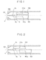
- Fig. 1 is a schematic sectional view of an ink-jet recording head and its periphery most properly showing the feature of the present invention.
- 101 indicates an ejection outlet
- 108 indicates an ejection outlet portion having the ejection outlet
- 102 indicates an electrothermal converting element as a first heater generating a thermal energy according to application of a predetermined electric current
- 103 indicates an electrothermal converting element as a second heater.
- O indicates the areal center of the ejection outlet 101
- HC A and HC B indicate the areal centers of the electrothermal converting elements 102 and 103, respectively.
- the centers of the effective heating areas which especially directly contribute to generation of bubbles, may also be regarded as areal centers.
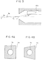
- Fig. 3 is a detailed view of the principal portion for further illustration of the present invention.
- ⁇ 1 is an angle of the line O-HC A relative to the center line of the ink channel
- ⁇ A is an angle between the ink-ejecting direction and the center line of the ink channel when ink drops are ejected based on such an ink channel structure.
- FIGs. 4A and 4B are schematic drawings showing the ejection outlets and the sections of ink channels employed in this example.
- S O indicates the area of the ejection outlet
- S N indicates the cross sectional area in the direction perpendicular to the longitudinal direction of the ink channel.
- ⁇ 1 and ⁇ A will be determined with reference to Fig. 3.
- the angle ⁇ A is formed between the center line of the ink channel and the direction of F which is the resultant force of the pressure F d in the ⁇ 1 direction and the pressure F o along the center line of the ink channel. Accordingly, ⁇ A can be determined by determining the ratio between F o and F d .
- Fx is defined as the ink-ejecting-directional component of the bubbling pressure derived from the electrothermal converting element 102
- F x substantially equals F
- F d S O S N ⁇ F x
- the other pressure can be expressed as F o as follows.
- F o S N -S O S N F x
- the F d /F o ratio can be expressed by S o /(S N - S o ).
- ⁇ 1 and ⁇ 2 the equation relative to the direction of the resultant force F can be expressed as follows.
- tan ⁇ A S o sin ⁇ 1 S N -S O (1-cos ⁇ 1 )
- ⁇ 1 is less than 12°, and therefore, the value of [1 - cos ⁇ 1 ] is substantially zero. Accordingly, the above equation can be expressed as follows.
- tan ⁇ A S O S N sin ⁇ 1
- ⁇ B the ink-ejecting direction according to bubbling by the non-illustrated second electrothermal converting element
- ⁇ 2 is the angle formed between the center line of the ink channel and the line O-HC B .
- the narrowed angle ⁇ f in the ink-ejecting direction calculated by ⁇ A + ⁇ B can be determined as follows.
- ⁇ f tan -1 S O S N (Sin ⁇ 1 +Sin ⁇ 2 ) S N 2 -S O 2 Sin ⁇ 1 Sin ⁇ 2
- Table 1 Picture Element Density (dpi) Picture Element Pitch ( ⁇ m) Ink-impacting Position Error for One Picture Element at 1.0 mm Distance (deg) Ink-impacting Position Error for Half Picture Element at 1.0 mm Distance (deg) 300 84.7 4.9 2.4 360 70.5 4.0 2.0 400 63.5 3.6 1.8
- the ink-impacting position error level should fall within 4.9° when the maximum ink-impacting position error is assumed as one picture element value. Further, when the maximum ink-impacting position error is assumed as half picture element value, the ink-impacting position error level should fall within 2.4°. Accordingly, the above-determined ⁇ f should satisfy 0° ⁇ ⁇ f ⁇ 5°, and more preferably, 0° ⁇ ⁇ f ⁇ 3°.
- Table 2 Type ⁇ 1 (deg) ⁇ 2 (deg) S o ( ⁇ m) S N ( ⁇ m) ⁇ f (deg) Quality A 2 4 900 2500 2.2 Very Good B 4 6 900 2500 3.6 Good C 6 8 900 2500 5.0 Good D 8 10 900 2500 6.4 Bad E 6 8 400 2500 2.2 Very Good F 6 8 700 2500 3.9 Good G 6 8 1000 2500 5.6 Bad
- the distance between the first and second electrothermal converting elements is required to be 2 ⁇ m or more in view of deposition performance, and the width of each electrothermal converting element requires an additional 2 ⁇ m or more around the effective heating zone, namely, 4 ⁇ m or more in total.
- the distance between the areal center of each electrothermal converting element and that of the ejection output is at most 300 ⁇ m, and therefore, the angle ⁇ between the areal centers of the first and second electrothermal converting elements via the areal center of the ejection outlet is determined as follows.
- the minimum value of the narrowed angle ⁇ f in the ink-ejecting direction is calculated at 0.1° by substitution of the above-described values, namely, 0.1° ⁇ ⁇ f .
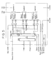
- FIG. 6 Ink in an ink-ejecting nozzle 104 is heated for bubble generation by electrothermal converting elements 3 and 4, and ejected from a laterally opened ejection outlet 101.
- the reference number 1 indicates an common lead wire 1 electrically connected to each heater, and 6 and 7 indicate selective lead wires for individually driving each heater.
- a substrate 23 is stuck to a base plate 41, and nozzle walls 5 are formed so as to be integrated with a grooved member 105.
- Fig. 7 is a perspective view of an example ink-jet recording apparatus carrying an ink-jet recording head which has the above-described structure.
- This ink-jet recording apparatus IJRA has a leading screw 2040 whose rotation is interlocked with front or reverse rotation of a driving motor 2010 through driving-force-transmitting gears 2020 and 2030.
- a carriage HC carrying an ink-jet cartridge IJC comprising an ink-jet recording head integrated with an ink tank is supported with a carriage shaft 2050 and the leading screw 2040, has a pin (not illustrated) engaged be a spiral groove 2041 on the leading screw 2040, and moves left and right, namely, in the directions of arrows a and b in accordance with rotation of the lead screw 2040.
- the referential number 2060 indicates a sheet-pressing plate which presses a paper sheet P against a platen roller 2070 over the range where the carriage moves.
- the referential numbers 2080 and 2090 indicate parts of a photo-coupler which function as home-position-detecting means for processes such as switching the rotating direction of the motor 2010 according to recognition of the presence of a lever 2100 joined to the carriage HC when the lever comes to the position of the coupler.
- the referential number 2110 indicates a cap member to cap the entire surface of the recording head, and the member is supported by a supporting member 2120.
- the referential number 2130 indicates a sucking means for sucking the inside of the cap, and the recording head is sucked for recovery by the sucking means through an opening in the cap.
- a cleaning blade 2140 which cleans the end face of the recording head is disposed on a member 2150 so as to be capable of moving forward and backward, and these blade and member are supported by a main-body-supporting plate 2160.
- the form of the blade 2140 is not limited to the above, and any type of publicly-known cleaning blade can be used in this example.
- a lever 2170 functioning to recover the suction for recovery of the recording head is disposed so as to move in accordance with movement of a cam 2180 engaged with the carriage HC, and according to such a mechanism, the driving force derived from the driving motor 2010 is controlled by a publicly-known transmitting means such as clutch switching.
- each process of capping, cleaning, and suction for recovery of the head is carried out desirably at a position corresponding to the process by action of the lead screw 2040 when the carriage HC enters a zone near the home position.
- any type of structure in which desired processes are carried out with known timing can be employed for this example.
- Fig. 2 is a schematic sectional view illustrating the structure around the ink channel of another ink-jet recording head according to the present invention. Although the distance between HC A and the front end of the nozzle was different from that between HC B and the same, results similar in Example 1 could be obtained by properly determining ⁇ 1 and ⁇ 2 .
- FIG. 8 is a schematic view illustrating the ink-ejecting angle.
- Fig. 9 is a schematic perspective sectional view showing the structure of nozzles and their peripheries in this example.
- heating resistor members are disposed within one nozzle in the above examples, similar results can also be achieved, needless to say, in cases where three or more of heating resistor members are disposed within one nozzle by determining the maximum ⁇ f value.
Landscapes
- Physics & Mathematics (AREA)
- Geometry (AREA)
- Particle Formation And Scattering Control In Inkjet Printers (AREA)
- Ink Jet (AREA)
Abstract
Description
- The present invention relates to ink-jet heads and apparatuses used in printers, video printers and others serving as output terminal units for copying machines, facsimile machines, word processors, host computers and others. In particular, the present invention relates to an ink-jet head and an ink-jet apparatus having a base member comprising an electrothermal converting element which generates thermal energy utilized as recording energy. Incidentally, the term "recording" used here implies ink application and other activities (printing) onto any type of ink-receiving material such as cloth, thread, paper, and sheet materials, and the term "recording apparatus" implies various types of information-processing apparatuses and printers serving as output units used in such apparatuses. Accordingly, the present invention is applicable for these usages.
- Recently, ink-jet recording apparatuses are increasingly required to be of smaller size, lower price, and in addition, have abilities for color recording and higher image quality recording. Hitherto, since a precise and complex structure and control of the recording head was necessary for achieving high image quality, recording apparatuses were extremely expensive and of large size.
- In relation to this, Japanese Examined Patent Publication No. 62-48585 discloses an ink-jet recording apparatus capable of modulating dot sizes while using a markedly simple mechanism in which two or more of electrothermal converting elements (including large one and small one) are disposed within one nozzle, and thus achieving high image quality. This invention is significant for gray-scale recording.
- Practically, when ink-ejecting quantity is modulated for achieving high image quality while using two electrothermal converting elements within one nozzle, each of the parallel-disposed electrothermal converting elements is generally individually driven. It has been revealed, however, that merely disposing the electrothermal converting elements in parallel cannot achieve an optimum ink-impacting position accuracy in some cases though a considerable accuracy can be achieved. In relation to this, the Inventors found that alteration of design parameters such as the distances between the electrothermal converting elements and an orifice, the size of the orifice, and others causes deterioration of the ink-impacting position accuracy, and therefore, the design must be wholly reformed in order to attain desired image quality. More specifically, alteration of some design parameters as described above leads to failure in satisfying practical levels, which may be attributed to complex factors arising from provision of two electrothermal converting elements within one nozzle and concerning nozzle designing for achieving high levels of ink-ejecting quantity and stability of the ejecting quantity. Further, the Inventors conducted the following examination in addition to examination of problems in related arts on designing the above-described electrothermal converting elements and the ink-impacting point. Ordinarily, factors on designing a nozzle and its periphery for achieving desired ink-impacting position accuracy are the orifice area, the nozzle length, the size and disposition of the electrothermal converting element, and others. The inventors examined designs of nozzles which contain a plurality of electrothermal converting elements while focusing the attention on the orifice area and the nozzle length among the above-listed factors, and found that a desired ink-impacting position accuracy can rarely be stably achieved possibly due to influence of other predominant factors. Meanwhile, among the parameters on designing a nozzle and its periphery, sizes of the electrothermal converting elements are determined at the point when a photomask used in a patterning step in a process for manufacturing a semiconductor substrate is designed. When the sizes of the electrothermal converting elements are altered aiming at achieving a desired ink-impacting position accuracy, the head must be produced almost newly. Accordingly, since the size and position of each electrothermal converting element should be altered at the last point of nozzle designing, there are considerable losses in view of time and workload. In contrast, only if the sizes and positions of the electrothermal converting elements can be determined beforehand, other ink-ejecting properties can easily be adjusted. For example, the orifice area can be minutely altered since methods for controlling the energy from a laser or the like for forming the orifice have been developed, and such an alteration is less causative of time loss and work inefficiency since forming the orifice is a relatively later step. Consequently, for a head having a plurality of electrothermal converting elements within one nozzle, it is particularly important to properly determine positions of the orifice and the electrothermal converting elements and others at an initial stage of nozzle designing.
- As described above, requirements on structure of a head having a plurality of heaters within one nozzle for achieving a high image quality have not yet been considered in detail in view of the relationship between the orifice and the electrothermal converting elements. Based on the above findings, the present invention is directed to solve difficulties in achieving a high image quality while using a head having a plurality of heaters within one nozzle, and to achieve recording with a higher image quality.
- The Inventors examined the parameters on head designing in order to improve ink-impacting position accuracy aiming at achieving high image quality recording, and found that stable achievement of a high image quality requires considering tendency of the influence upon ink-impacting position accuracy by the orifice area and positions of the two electrothermal converting elements relative to the orifice. The present invention has been accomplished based on this finding.
- Accordingly, an object of the present invention is to provide an ink-jet recording head, an ink-jet head cartridge and an ink-jet recording apparatus capable of achieving highly fine recording by specifying a head structure in which the positional relationship between a plurality of heaters and the areal center of an ejection outlet is carefully considered.
- The principal construction of the present invention for achieving the above object is as follows.
- (1) An ink-jet head comprising:
- an ejection outlet portion which has an ejection outlet, and is convergent toward said outlet;
- an ink channel communicating with said outlet;
- a first heater and a second heater which are disposed in said ink channel and can be individually driven; and
- an element substrate equipped with said heaters, wherein:
- said first heater and second heater have different heating powers and are distantly disposed from each other; and
- the following formula is satisfied with the angle θ1 formed between the areal center of said first heater and the projection point of the areal center of said ejection outlet onto the element substrate surface provided with said heaters via the areal center of said ejection outlet, the angle θ2 similarly formed but using the areal center of said second heating member, the sectional area SN of said ink channel perpendicular to the ink-ejecting direction, and the area SO of said ejection outlet.

- (2) An ink-jet head comprising:
- an ejection outlet portion which has an ejection outlet, and is convergent toward said outlet;
- a pressure chamber communicating with said outlet;
- a first heater and a second heater which are provided in said pressure chamber, disposed so as to oppose said ejection outlet, and can be individually driven; and
- an element substrate equipped with said heaters, wherein:
- said first heater and second heater have different heating powers and are distantly disposed from each other, and
- the following formula is satisfied with the angle θ1 formed between the areal center of said first heater and the projection point of the areal center of said ejection outlet onto the element substrate surface provided with said heaters via the areal center of said ejection outlet, the angle θ2 similarly formed but using the areal center of said second heating member, the sectional area SN of said pressure chamber perpendicular to said element substrate equipped with said heating members, and the area SO of said ejection outlet.

- (3) An ink-jet recording apparatus which can carry an ink-jet head according to the above paragraph (1) or (2), and has a means to send different driving signals to said first heater and second heater.
- (4) An ink-jet head cartridge comprising:
- an ink-jet head according to the above paragraph (1) or (2); and
- an ink-vessel holding ink to be supplied to said ink-jet head.
- Based on the above construction, ink-impacting position accuracy can be improved by inhibiting irregularity in the ink-impacting position in a case where each heater is individually driven, and thus gray-scale recording can be achieved with a high image quality.
-
- Fig. 1 is a schematic sectional view illustrating the structure around the ink channel of an ink-jet recording head according to the present invention;
- Fig. 2 is a schematic sectional view illustrating the structure around the ink channel of another ink-jet recording head according to the present invention;
- Fig. 3 is a schematic sectional view illustrating the structure of an ink channel in detail;
- Fig. 4 contains schematic diagrams showing the relationship between an ejection outlet portion and a sectional area of an ink channel in the present invention;
- Fig. 5 is a schematic diagram showing an equivalent circuit on an element substrate equipped with heaters;
- Fig. 6 is a schematic view illustrating the structure of a nozzle and its periphery in an ink-jet recording head of the present invention;
- Fig. 7 is a schematic view illustrating an ink-jet recording apparatus of the present invention;
- Fig. 8 is a schematic sectional view showing another example of an ink-jet recording head according to the present invention; and
- Fig. 9 is a schematic sectional view showing another example of an ink-jet recording head according to the present invention.
- Fig. 1 is a schematic sectional view of an ink-jet recording head and its periphery most properly showing the feature of the present invention. In this figure, 101 indicates an ejection outlet; 108 indicates an ejection outlet portion having the ejection outlet; 102 indicates an electrothermal converting element as a first heater generating a thermal energy according to application of a predetermined electric current; and 103 indicates an electrothermal converting element as a second heater.
- Further, O indicates the areal center of the
ejection outlet 101, and HCA and HCB indicate the areal centers of theelectrothermal converting elements - Additionally, Fig. 3 is a detailed view of the principal portion for further illustration of the present invention. In this figure, only the first heater among the above-mentioned heaters is shown in order to simplify illustration of the present invention, θ1 is an angle of the line O-HCA relative to the center line of the ink channel, and θA is an angle between the ink-ejecting direction and the center line of the ink channel when ink drops are ejected based on such an ink channel structure.
- Moreover, Figs. 4A and 4B are schematic drawings showing the ejection outlets and the sections of ink channels employed in this example. In these figures, SO indicates the area of the ejection outlet, and SN indicates the cross sectional area in the direction perpendicular to the longitudinal direction of the ink channel.
- Here, the relationship between θ1 and θA will be determined with reference to Fig. 3. The angle θA is formed between the center line of the ink channel and the direction of F which is the resultant force of the pressure Fd in the θ1 direction and the pressure Fo along the center line of the ink channel. Accordingly, θA can be determined by determining the ratio between Fo and Fd.
- Additionally, when Fx is defined as the ink-ejecting-directional component of the bubbling pressure derived from the electrothermal converting
element 102, Fx substantially equals F, and therefore the pressure Fd upon the area SO of the ejection outlet can be expressed according to the following formula.

- Accordingly, the Fd/Fo ratio can be expressed by So/(SN - So). Using this ratio, θ1 and θ2, the equation relative to the direction of the resultant force F can be expressed as follows.


- Similarly, the relationship between θB and θ2 can be expressed as follows, wherein θB is the ink-ejecting direction according to bubbling by the non-illustrated second electrothermal converting element, and θ2 is the angle formed between the center line of the ink channel and the line O-HCB.

- Consequently, when ink is ejected according to bubbling by both first and second electrothermal converting elements, the narrowed angle θf in the ink-ejecting direction calculated by θA + θB can be determined as follows.


- Here, ink-impacting position error levels required for various image qualities are shown in Table 1 below.
Table 1 Picture Element Density (dpi) Picture Element Pitch (µm) Ink-impacting Position Error for One Picture Element at 1.0 mm Distance (deg) Ink-impacting Position Error for Half Picture Element at 1.0 mm Distance (deg) 300 84.7 4.9 2.4 360 70.5 4.0 2.0 400 63.5 3.6 1.8 - As shown in Table 1, in a case where ink drops are ejected from one ejection outlet, the ink-impacting position error level should fall within 4.9° when the maximum ink-impacting position error is assumed as one picture element value. Further, when the maximum ink-impacting position error is assumed as half picture element value, the ink-impacting position error level should fall within 2.4°. Accordingly, the above-determined θf should satisfy 0° < θf ≤ 5°, and more preferably, 0° < θf ≤ 3°.
- Based on the above-described designing rule, the positions of the electrothermal converting elements and the orifice area were determined, and several types of ink-jet heads were manufactured. The design parameters and the resulting image qualities of the practically manufactured ink-jet heads are shown in Table 2 below.
Table 2 Type θ1 (deg) θ2 (deg) So (µm) SN (µm) θf (deg) Quality A 2 4 900 2500 2.2 Very Good B 4 6 900 2500 3.6 Good C 6 8 900 2500 5.0 Good D 8 10 900 2500 6.4 Bad E 6 8 400 2500 2.2 Very Good F 6 8 700 2500 3.9 Good G 6 8 1000 2500 5.6 Bad - Incidentally, when nozzles are designed according to the ordinary designing rule, the distance between the first and second electrothermal converting elements is required to be 2 µm or more in view of deposition performance, and the width of each electrothermal converting element requires an additional 2 µm or more around the effective heating zone, namely, 4 µm or more in total.
- Further, the distance between the areal center of each electrothermal converting element and that of the ejection output is at most 300 µm, and therefore, the angle θ between the areal centers of the first and second electrothermal converting elements via the areal center of the ejection outlet is determined as follows.


- Moreover, when the sectional area SN of the ink channel is set as 2500 µm2, the area So of the ejection outlet requires at least 400 µm2. Accordingly, the minimum value of the narrowed angle θf in the ink-ejecting direction is calculated at 0.1° by substitution of the above-described values, namely, 0.1° ≤ θf.
- Next, the practical structure of the above-described heads will be illustrated below. The structure around the nozzles is shown in Fig. 6. Ink in an ink-ejecting
nozzle 104 is heated for bubble generation by electrothermal convertingelements ejection outlet 101. Thereference number 1 indicates ancommon lead wire 1 electrically connected to each heater, and 6 and 7 indicate selective lead wires for individually driving each heater. Asubstrate 23 is stuck to abase plate 41, andnozzle walls 5 are formed so as to be integrated with agrooved member 105. - Fig. 7 is a perspective view of an example ink-jet recording apparatus carrying an ink-jet recording head which has the above-described structure. This ink-jet recording apparatus IJRA has a
leading screw 2040 whose rotation is interlocked with front or reverse rotation of a drivingmotor 2010 through driving-force-transmittinggears carriage shaft 2050 and theleading screw 2040, has a pin (not illustrated) engaged be aspiral groove 2041 on theleading screw 2040, and moves left and right, namely, in the directions of arrows a and b in accordance with rotation of thelead screw 2040. Thereferential number 2060 indicates a sheet-pressing plate which presses a paper sheet P against aplaten roller 2070 over the range where the carriage moves. Thereferential numbers motor 2010 according to recognition of the presence of alever 2100 joined to the carriage HC when the lever comes to the position of the coupler. Thereferential number 2110 indicates a cap member to cap the entire surface of the recording head, and the member is supported by a supporting member 2120. Thereferential number 2130 indicates a sucking means for sucking the inside of the cap, and the recording head is sucked for recovery by the sucking means through an opening in the cap. Acleaning blade 2140 which cleans the end face of the recording head is disposed on amember 2150 so as to be capable of moving forward and backward, and these blade and member are supported by a main-body-supportingplate 2160. As a matter of course, the form of theblade 2140 is not limited to the above, and any type of publicly-known cleaning blade can be used in this example. Additionally, alever 2170 functioning to recover the suction for recovery of the recording head is disposed so as to move in accordance with movement of acam 2180 engaged with the carriage HC, and according to such a mechanism, the driving force derived from the drivingmotor 2010 is controlled by a publicly-known transmitting means such as clutch switching. - In the above-described structure, each process of capping, cleaning, and suction for recovery of the head is carried out desirably at a position corresponding to the process by action of the
lead screw 2040 when the carriage HC enters a zone near the home position. Needless to say, any type of structure in which desired processes are carried out with known timing can be employed for this example. - Fig. 2 is a schematic sectional view illustrating the structure around the ink channel of another ink-jet recording head according to the present invention. Although the distance between HCA and the front end of the nozzle was different from that between HCB and the same, results similar in Example 1 could be obtained by properly determining θ1 and θ2.
- In this example, as shown in Figs. 8 and 9, an
ejection outlet 101 is formed in parallel to the surface of anelement substrate 23 equipped withheating resistors - According to the same calculation as illustrated in Example 1, the following equation expressing the relationship between the positions of the heating resistors and ink-ejecting direction can be obtained.

- As described above, false ink-impacting position when ink bubbles are generated by two electrothermal converting elements can be prevented and high image quality can be achieved in such a case where the following formula is satisfied with the angle θ1 of the areal center of a first heating resistor member relative to the areal center of an orifice in a ejection outlet portion; the angle θ2 of the areal center of a second heating resistor member relative to the same; the sectional area SN of an ink channel when the channel is sectioned perpendicular to the ink-ejecting direction; and the area So of the orifice.


- Although two heating resistor members are disposed within one nozzle in the above examples, similar results can also be achieved, needless to say, in cases where three or more of heating resistor members are disposed within one nozzle by determining the maximum θf value.
Claims (13)
- An ink-jet head comprising:an ejection outlet portion which has an ejection outlet, and is convergent toward said outlet;an ink channel communicating with said outlet;a first heater and a second heater which are disposed in said ink channel and can be individually driven; andan element substrate equipped with said heaters, wherein:said first heater and second heater have different heating powers and are distantly disposed from each other; andthe following formula:

- The ink-jet head according to Claim 1, wherein the following formula:

- The ink-jet head according to Claim 1, wherein the areal centers of said heaters are the centers of the effective heating areas.
- The ink-jet head according to Claim 1, wherein the area of said first heater is different from that of said second heater.
- The ink-jet head according to Claim 1, wherein said angles θ1 and θ2 are substantially equal.
- The ink-jet head according to Claim 1, wherein said angles θ1 is different from said angle θ2.
- An ink-jet head comprising:an ejection outlet portion which has an ejection outlet, and is convergent toward said outlet;a pressure chamber communicating with said outlet;a first heater and a second heater which are provided in said pressure chamber, disposed so as to oppose said ejection outlet, and can be individually driven; andan element substrate equipped with said heaters, wherein:said first heater and second heater have different heating powers and are distantly disposed; andthe following formula:

- The ink-jet head according to Claim 1 or 7, wherein one or both of said heaters are electrothermal converting elements.
- An ink-jet recording apparatus which achieves recording by ink-ejecting, and comprises an ink-jet head and a driving signal supplying circuit,
said ink-jet head comprising:an ejection outlet portion which has an ejection outlet, and is convergent toward said outlet;an ink channel communicating with said outlet;a first heater and a second heater which are disposed in said ink channel and can be individually driven; andan element substrate equipped with said heaters, said circuit supplying individual driving signals for said first heater and second heater,
wherein:said first heater and second heater have different heating powers and are distantly disposed; andthe following formula:formed but using the areal center of said second heating member, the sectional area SN of said ink channel perpendicular to the ink-ejecting direction, and the area So of said ejection outlet.
- An ink-jet recording apparatus which achieves recording by ink-ejecting, and comprises an ink-jet head and a driving signal supplying circuit,
said ink-jet head comprising:an ejection outlet portion which has an ejection outlet, and is convergent toward said outlet;a pressure chamber communicating with said outlet;a first heater and a second heater which are provided in said pressure chamber, disposed so as to oppose said ejection outlet, and can be individually driven; andan element substrate equipped with said heaters, said circuit supplying individual driving signals for said first heater and second heater,
wherein:said first heater and second heater have different heating powers and are distantly disposed; andthe following formula:
- An ink-jet head cartridge comprising:an ink-jet head according to Claim 1 or 7; andan ink-vessel holding ink to be supplied to said ink-jet head.
- An ink jet head or a recording apparatus or method using such a head wherein the relationship between the cross-sectional area SN of an ink channel, the area SO of an ink ejection outlet and the angles θ1 and θ2 of respective lines from a centre of each heating element to the centre of the ejection outlet to a centre line of the channel satisfy:

- An ink jet head or recording apparatus using such an ink jet head having the features recited in any one or any combination of the preceding claims.
Applications Claiming Priority (3)
| Application Number | Priority Date | Filing Date | Title |
|---|---|---|---|
| JP10017296 | 1996-04-22 | ||
| JP100172/96 | 1996-04-22 | ||
| JP10017296A JP3559647B2 (en) | 1996-04-22 | 1996-04-22 | Ink jet recording head, ink jet head cartridge and ink jet recording apparatus |
Publications (3)
| Publication Number | Publication Date |
|---|---|
| EP0803361A2 true EP0803361A2 (en) | 1997-10-29 |
| EP0803361A3 EP0803361A3 (en) | 1998-08-19 |
| EP0803361B1 EP0803361B1 (en) | 2003-07-30 |
Family
ID=14266909
Family Applications (1)
| Application Number | Title | Priority Date | Filing Date |
|---|---|---|---|
| EP97302703A Expired - Lifetime EP0803361B1 (en) | 1996-04-22 | 1997-04-21 | Ink-jet head, ink-jet cartridge, and ink jet recording apparatus |
Country Status (4)
| Country | Link |
|---|---|
| US (1) | US6290335B1 (en) |
| EP (1) | EP0803361B1 (en) |
| JP (1) | JP3559647B2 (en) |
| DE (1) | DE69723758T2 (en) |
Cited By (1)
| Publication number | Priority date | Publication date | Assignee | Title |
|---|---|---|---|---|
| EP1356937A3 (en) * | 2002-04-23 | 2004-01-14 | Canon Kabushiki Kaisha | Ink jet head |
Families Citing this family (8)
| Publication number | Priority date | Publication date | Assignee | Title |
|---|---|---|---|---|
| JP2003025577A (en) * | 2001-07-11 | 2003-01-29 | Canon Inc | Liquid jet head |
| US6705716B2 (en) * | 2001-10-11 | 2004-03-16 | Hewlett-Packard Development Company, L.P. | Thermal ink jet printer for printing an image on a receiver and method of assembling the printer |
| JP2006088711A (en) * | 2002-04-16 | 2006-04-06 | Sony Corp | Liquid ejecting device and liquid ejecting method |
| SG116514A1 (en) * | 2002-11-13 | 2005-11-28 | Sony Corp | Liquid-ejecting method and liquid-ejecting apparatus. |
| US6755509B2 (en) * | 2002-11-23 | 2004-06-29 | Silverbrook Research Pty Ltd | Thermal ink jet printhead with suspended beam heater |
| KR20050113644A (en) * | 2003-03-20 | 2005-12-02 | 소니 가부시끼 가이샤 | Liquid-jet head and liquid-jet device using the head |
| JP3972363B2 (en) * | 2003-06-11 | 2007-09-05 | ソニー株式会社 | Liquid ejection apparatus and liquid ejection method |
| CN1968815B (en) * | 2004-06-28 | 2013-05-01 | 佳能株式会社 | Manufacturing method for liquid ejecting head and liquid ejecting head obtained by this method |
Citations (10)
| Publication number | Priority date | Publication date | Assignee | Title |
|---|---|---|---|---|
| US4317124A (en) * | 1979-02-14 | 1982-02-23 | Canon Kabushiki Kaisha | Ink jet recording apparatus |
| EP0124312A2 (en) * | 1983-04-29 | 1984-11-07 | Hewlett-Packard Company | Resistor structures for thermal ink jet printers |
| JPS62261452A (en) * | 1986-05-09 | 1987-11-13 | Canon Inc | Multivalued recording |
| JPH01235652A (en) * | 1988-03-16 | 1989-09-20 | Ricoh Co Ltd | Liquid jet recording |
| US5121143A (en) * | 1988-09-14 | 1992-06-09 | Graphtec Corp. | Ink printing head with variable-size heat elements |
| US5172139A (en) * | 1989-05-09 | 1992-12-15 | Ricoh Company, Ltd. | Liquid jet head for gradation recording |
| EP0613781A1 (en) * | 1993-02-26 | 1994-09-07 | Canon Kabushiki Kaisha | Ink jet printing head, ink jet head cartridge and printing apparatus |
| EP0707964A2 (en) * | 1994-10-20 | 1996-04-24 | Canon Kabushiki Kaisha | Liquid jet head, head cartridge, liquid jet apparatus, method of ejecting liquid, and method of injecting ink |
| EP0707963A2 (en) * | 1994-10-20 | 1996-04-24 | Canon Kabushiki Kaisha | Ink jet head, ink jet head cartridge and ink jet apparatus |
| EP0747221A2 (en) * | 1995-06-06 | 1996-12-11 | Canon Kabushiki Kaisha | Ink jet head, ink jet apparatus and ink jet recording method |
Family Cites Families (12)
| Publication number | Priority date | Publication date | Assignee | Title |
|---|---|---|---|---|
| US4450455A (en) | 1981-06-18 | 1984-05-22 | Canon Kabushiki Kaisha | Ink jet head |
| US4558333A (en) | 1981-07-09 | 1985-12-10 | Canon Kabushiki Kaisha | Liquid jet recording head |
| US4611219A (en) | 1981-12-29 | 1986-09-09 | Canon Kabushiki Kaisha | Liquid-jetting head |
| JPS59123672A (en) | 1982-12-28 | 1984-07-17 | Canon Inc | Liquid jet recorder |
| US4646110A (en) | 1982-12-29 | 1987-02-24 | Canon Kabushiki Kaisha | Liquid injection recording apparatus |
| US4881318A (en) | 1984-06-11 | 1989-11-21 | Canon Kabushiki Kaisha | Method of manufacturing a liquid jet recording head |
| JPS6248585A (en) | 1985-08-28 | 1987-03-03 | Sony Corp | Thermal recording paper |
| EP0345724B1 (en) | 1988-06-07 | 1995-01-18 | Canon Kabushiki Kaisha | Liquid jet recording head and recording device having the same head |
| US5068674A (en) | 1988-06-07 | 1991-11-26 | Canon Kabushiki Kaisha | Liquid jet recording head stabilization |
| CA2025561C (en) | 1989-09-18 | 1995-07-11 | Seiichiro Karita | Recording head with cover |
| DE69025958T2 (en) | 1989-09-18 | 1996-11-14 | Canon Kk | Ink jet recording head and ink jet device with this head |
| ATE200250T1 (en) | 1989-09-18 | 2001-04-15 | Canon Kk | INK JET DEVICE |
-
1996
- 1996-04-22 JP JP10017296A patent/JP3559647B2/en not_active Expired - Fee Related
-
1997
- 1997-04-21 US US08/844,597 patent/US6290335B1/en not_active Expired - Fee Related
- 1997-04-21 EP EP97302703A patent/EP0803361B1/en not_active Expired - Lifetime
- 1997-04-21 DE DE69723758T patent/DE69723758T2/en not_active Expired - Lifetime
Patent Citations (10)
| Publication number | Priority date | Publication date | Assignee | Title |
|---|---|---|---|---|
| US4317124A (en) * | 1979-02-14 | 1982-02-23 | Canon Kabushiki Kaisha | Ink jet recording apparatus |
| EP0124312A2 (en) * | 1983-04-29 | 1984-11-07 | Hewlett-Packard Company | Resistor structures for thermal ink jet printers |
| JPS62261452A (en) * | 1986-05-09 | 1987-11-13 | Canon Inc | Multivalued recording |
| JPH01235652A (en) * | 1988-03-16 | 1989-09-20 | Ricoh Co Ltd | Liquid jet recording |
| US5121143A (en) * | 1988-09-14 | 1992-06-09 | Graphtec Corp. | Ink printing head with variable-size heat elements |
| US5172139A (en) * | 1989-05-09 | 1992-12-15 | Ricoh Company, Ltd. | Liquid jet head for gradation recording |
| EP0613781A1 (en) * | 1993-02-26 | 1994-09-07 | Canon Kabushiki Kaisha | Ink jet printing head, ink jet head cartridge and printing apparatus |
| EP0707964A2 (en) * | 1994-10-20 | 1996-04-24 | Canon Kabushiki Kaisha | Liquid jet head, head cartridge, liquid jet apparatus, method of ejecting liquid, and method of injecting ink |
| EP0707963A2 (en) * | 1994-10-20 | 1996-04-24 | Canon Kabushiki Kaisha | Ink jet head, ink jet head cartridge and ink jet apparatus |
| EP0747221A2 (en) * | 1995-06-06 | 1996-12-11 | Canon Kabushiki Kaisha | Ink jet head, ink jet apparatus and ink jet recording method |
Non-Patent Citations (2)
| Title |
|---|
| PATENT ABSTRACTS OF JAPAN vol. 12, no. 141 (M-691), 28 April 1988 & JP 62 261452 A (CANON INC), 13 November 1987, * |
| PATENT ABSTRACTS OF JAPAN vol. 13, no. 565 (M-907), 14 December 1989 & JP 01 235652 A (RICOH CO LTD), 20 September 1989, * |
Cited By (2)
| Publication number | Priority date | Publication date | Assignee | Title |
|---|---|---|---|---|
| EP1356937A3 (en) * | 2002-04-23 | 2004-01-14 | Canon Kabushiki Kaisha | Ink jet head |
| US6984025B2 (en) | 2002-04-23 | 2006-01-10 | Canon Kabushiki Kaisha | Ink jet head |
Also Published As
| Publication number | Publication date |
|---|---|
| EP0803361A3 (en) | 1998-08-19 |
| JP3559647B2 (en) | 2004-09-02 |
| JPH09286105A (en) | 1997-11-04 |
| EP0803361B1 (en) | 2003-07-30 |
| DE69723758T2 (en) | 2004-06-03 |
| DE69723758D1 (en) | 2003-09-04 |
| US6290335B1 (en) | 2001-09-18 |
Similar Documents
| Publication | Publication Date | Title |
|---|---|---|
| EP0313341B1 (en) | Thermal ink-jet head structure | |
| KR100874733B1 (en) | High-performance, high-density ink jet printhead having multiple modes of operation | |
| EP1894727A2 (en) | Liquid jet head | |
| JP2875915B2 (en) | Recording device | |
| US6224183B1 (en) | Ink-jet printing apparatus and facsimile apparatus | |
| US7959260B2 (en) | Ink jet recording method | |
| EP0803361A2 (en) | Ink-jet head, ink-jet cartridge, and ink jet recording apparatus | |
| EP0670220A2 (en) | An ink jet recording apparatus | |
| EP0570988B1 (en) | Ink jet recording system | |
| JP5188049B2 (en) | Recording head | |
| JP2726135B2 (en) | Ink jet recording device | |
| JPH04278361A (en) | Ink jet recorder | |
| JP3178583B2 (en) | Inkjet printer | |
| JPH07179248A (en) | Recorder | |
| JP3026685B2 (en) | Ink jet recording device | |
| JP3313884B2 (en) | Inkjet recording method | |
| JP3233368B2 (en) | Recording device | |
| JPH07276736A (en) | Recording device | |
| JP3025110B2 (en) | Ink jet recording device | |
| JPH05159112A (en) | Recorder | |
| JP4280502B2 (en) | Recording apparatus and recording method | |
| JPH04347642A (en) | Thermal recording apparatus | |
| JPH05124192A (en) | Recorder | |
| JP3045618B2 (en) | Recording device | |
| JPH0768896A (en) | Recording device |
Legal Events
| Date | Code | Title | Description |
|---|---|---|---|
| PUAI | Public reference made under article 153(3) epc to a published international application that has entered the european phase |
Free format text: ORIGINAL CODE: 0009012 |
|
| AK | Designated contracting states |
Kind code of ref document: A2 Designated state(s): DE FR GB IT |
|
| PUAL | Search report despatched |
Free format text: ORIGINAL CODE: 0009013 |
|
| AK | Designated contracting states |
Kind code of ref document: A3 Designated state(s): DE FR GB IT |
|
| 17P | Request for examination filed |
Effective date: 19990107 |
|
| 17Q | First examination report despatched |
Effective date: 20000904 |
|
| GRAG | Despatch of communication of intention to grant |
Free format text: ORIGINAL CODE: EPIDOS AGRA |
|
| GRAG | Despatch of communication of intention to grant |
Free format text: ORIGINAL CODE: EPIDOS AGRA |
|
| GRAG | Despatch of communication of intention to grant |
Free format text: ORIGINAL CODE: EPIDOS AGRA |
|
| GRAH | Despatch of communication of intention to grant a patent |
Free format text: ORIGINAL CODE: EPIDOS IGRA |
|
| GRAH | Despatch of communication of intention to grant a patent |
Free format text: ORIGINAL CODE: EPIDOS IGRA |
|
| GRAA | (expected) grant |
Free format text: ORIGINAL CODE: 0009210 |
|
| AK | Designated contracting states |
Designated state(s): DE FR GB IT |
|
| REG | Reference to a national code |
Ref country code: GB Ref legal event code: FG4D |
|
| REF | Corresponds to: |
Ref document number: 69723758 Country of ref document: DE Date of ref document: 20030904 Kind code of ref document: P |
|
| ET | Fr: translation filed | ||
| PLBE | No opposition filed within time limit |
Free format text: ORIGINAL CODE: 0009261 |
|
| STAA | Information on the status of an ep patent application or granted ep patent |
Free format text: STATUS: NO OPPOSITION FILED WITHIN TIME LIMIT |
|
| 26N | No opposition filed |
Effective date: 20040504 |
|
| REG | Reference to a national code |
Ref country code: FR Ref legal event code: PLFP Year of fee payment: 19 |
|
| PGFP | Annual fee paid to national office [announced via postgrant information from national office to epo] |
Ref country code: DE Payment date: 20150430 Year of fee payment: 19 Ref country code: GB Payment date: 20150424 Year of fee payment: 19 |
|
| PGFP | Annual fee paid to national office [announced via postgrant information from national office to epo] |
Ref country code: IT Payment date: 20150424 Year of fee payment: 19 Ref country code: FR Payment date: 20150424 Year of fee payment: 19 |
|
| REG | Reference to a national code |
Ref country code: DE Ref legal event code: R119 Ref document number: 69723758 Country of ref document: DE |
|
| GBPC | Gb: european patent ceased through non-payment of renewal fee |
Effective date: 20160421 |
|
| REG | Reference to a national code |
Ref country code: FR Ref legal event code: ST Effective date: 20161230 |
|
| PG25 | Lapsed in a contracting state [announced via postgrant information from national office to epo] |
Ref country code: GB Free format text: LAPSE BECAUSE OF NON-PAYMENT OF DUE FEES Effective date: 20160421 Ref country code: FR Free format text: LAPSE BECAUSE OF NON-PAYMENT OF DUE FEES Effective date: 20160502 Ref country code: DE Free format text: LAPSE BECAUSE OF NON-PAYMENT OF DUE FEES Effective date: 20161101 |
|
| PG25 | Lapsed in a contracting state [announced via postgrant information from national office to epo] |
Ref country code: IT Free format text: LAPSE BECAUSE OF NON-PAYMENT OF DUE FEES Effective date: 20160421 |