EP0803448A1 - Box, blank for forming the box, and fixing device for the box - Google Patents
Box, blank for forming the box, and fixing device for the box Download PDFInfo
- Publication number
- EP0803448A1 EP0803448A1 EP96810264A EP96810264A EP0803448A1 EP 0803448 A1 EP0803448 A1 EP 0803448A1 EP 96810264 A EP96810264 A EP 96810264A EP 96810264 A EP96810264 A EP 96810264A EP 0803448 A1 EP0803448 A1 EP 0803448A1
- Authority
- EP
- European Patent Office
- Prior art keywords
- box
- box according
- section
- flaps
- blank
- Prior art date
- Legal status (The legal status is an assumption and is not a legal conclusion. Google has not performed a legal analysis and makes no representation as to the accuracy of the status listed.)
- Granted
Links
Images


Classifications
-
- B—PERFORMING OPERATIONS; TRANSPORTING
- B65—CONVEYING; PACKING; STORING; HANDLING THIN OR FILAMENTARY MATERIAL
- B65D—CONTAINERS FOR STORAGE OR TRANSPORT OF ARTICLES OR MATERIALS, e.g. BAGS, BARRELS, BOTTLES, BOXES, CANS, CARTONS, CRATES, DRUMS, JARS, TANKS, HOPPERS, FORWARDING CONTAINERS; ACCESSORIES, CLOSURES, OR FITTINGS THEREFOR; PACKAGING ELEMENTS; PACKAGES
- B65D5/00—Rigid or semi-rigid containers of polygonal cross-section, e.g. boxes, cartons or trays, formed by folding or erecting one or more blanks made of paper
- B65D5/42—Details of containers or of foldable or erectable container blanks
- B65D5/44—Integral, inserted or attached portions forming internal or external fittings
- B65D5/441—Reinforcements
- B65D5/443—Integral reinforcements, e.g. folds, flaps
-
- B—PERFORMING OPERATIONS; TRANSPORTING
- B65—CONVEYING; PACKING; STORING; HANDLING THIN OR FILAMENTARY MATERIAL
- B65D—CONTAINERS FOR STORAGE OR TRANSPORT OF ARTICLES OR MATERIALS, e.g. BAGS, BARRELS, BOTTLES, BOXES, CANS, CARTONS, CRATES, DRUMS, JARS, TANKS, HOPPERS, FORWARDING CONTAINERS; ACCESSORIES, CLOSURES, OR FITTINGS THEREFOR; PACKAGING ELEMENTS; PACKAGES
- B65D83/00—Containers or packages with special means for dispensing contents
- B65D83/08—Containers or packages with special means for dispensing contents for dispensing thin flat articles in succession
- B65D83/0805—Containers or packages with special means for dispensing contents for dispensing thin flat articles in succession through an aperture in a wall
Definitions
- the invention relates to a box according to the preamble of claim 1.
- Such boxes are known and are used, for example, for dispensing paper towels and the like. They are simple and inexpensive to manufacture, for example from cardboard or plastic.
- the invention further relates to a blank for forming the box and a fastening device for the box.
- the known boxes have the disadvantage, among other things, that they are not very stable when using thin cardboard and therefore offer only limited application possibilities. They are either used loosely, whereby the removal of an object contained in the interior takes up both hands of the user, or inserted in expensive dispenser containers made of metal or plastic.
- the invention has for its object to provide a generic box in which, while maintaining the extremely inexpensive and simple manufacture, a high degree of stability is achieved, and which also has a wide range of applications due to its ease of attachment.
- FIGS. 1 and 2 A first embodiment of the invention is described below with reference to FIGS. 1 and 2.
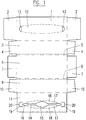
- FIG. 1 shows a plan view of a blank for a box according to a first embodiment of the invention, which is particularly suitable for the repeated removal of towels or the like.
- the blank 1 - 11 consists of a single, flat piece of cardboard, which is formed by punching or cutting out a larger piece of cardboard, with creasing, perforation or embossing lines (shown in broken lines or dash-dotted lines), which fold lines and / or tear lines are pre-punched for the box to be formed.
- the box is made of cardboard in this example, it can also be molded from a plastic film of suitable rigidity or a similar material.
- the blank comprises an outer upper wall section 1 with end flaps 2, a first side wall section 3 with end flaps 4, a first flap section 5, a bottom wall section 6 with end flaps 7, a second flap section 8, a second side wall section 9 with end flaps 10 and an inner upper wall section 11 .
- the different sections with their end flaps are foldably connected to one another via crease and perforation lines, as shown in FIG. 1.
- the outer upper wall section 1 has a tear-out strip 12 and openings 13 at its ends.
- the inner upper wall section 11 has a slot-shaped opening section 14, 15, 16, which is delimited by lateral, movable flaps 17 at least over part of its length.
- the flaps 17 are connected along perforation lines 18 to the inner upper wall section 11 of the box and, in the closed position, define a slot area which has slot sections 14 of approximately constant width and an enlarged central part 15.
- the slot sections 14 are adjoined on the outside by two cut end sections 16 which narrow outwards.
- the outer upper wall section 1 and the inner upper wall section 11 together form the upper wall of the box (see FIG. 2).
- the sections 1 and 11 are fixed to one another (for example glued) in such a way that the tearable strip 12 covers the opening section 14, 15, 16.
- the inner section 11, which has the flaps 17 delimiting the opening section 14, 15, 16, is provided on both sides (corresponding to the end openings 13) with a tongue 20 cut free by a cutting line 19 to facilitate the tearing out of the strip 12.
- a tongue 20 can deflect inwards when reaching under the strip 12.
- the intermediate product is held, pressure being exerted on the upper wall 1, 11 and on the side walls 3, 9, so that the tab sections 5 and 8 on the bottom wall section 6 are folded in and thereby folded together with it, after which it is known per se
- the end flaps 4 and 10 are folded inwards and the end flaps 2 and 7 are folded onto one another and fixed (for example glued).
- the two above reinforcing and guide flaps 21 are formed and fixed in their position without additional gluing.
- the tab sections 5 and 8 are first folded and glued to the bottom wall section 6. Then the side wall sections 3 and 9 and the end flaps 4, 10 and 7 are erected and glued in a manner known per se. After the product has been filled in, the package is then closed by folding and gluing the outer and inner upper wall sections 1 and 11 and the end flaps 2.
- FIG. 2 shows a perspective view of the box according to the first embodiment of the invention after the strip 12 has been torn out.
- the outer upper wall section 1 forms, together with the inner upper wall section 11, the upper wall of the box.
- the strip 12 (see FIG. 1) has already been torn out, so that the opening section 14, 15, 16 is exposed and part of the inner upper wall section 11 is also visible. That through the cutting line 19 cut tongue 20 is not shown in Figure 2.
- the tab section 5 is folded together with the bottom wall section 6 and forms the projecting tab 21. In exactly the same way, the other tab section 8 with the bottom wall section 6 on the other side also forms a projecting tab 21.
- the box can be made by simply folding and fixing it from the one-piece, pre-cut blank 1 - 11. At least one of the surfaces of the box (in the example shown the bottom wall section 6) has two parallel edges, each of which has a projecting tab 21. Depending on the molding process, these tabs 21 can be realized without any additional consumption of material or adhesive and while maintaining the inexpensive manufacture of the box.
- the tabs 21 lie essentially in the plane of the surface in question (the bottom wall 6) and run over the entire length of the respective opposite edges. They increase the stability of the box, which means that the packaging is better protected against mechanical deformation, which increases product protection. Above all, however, they can advantageously be used as an aid for fastening the box during its use as a dispenser.
- the box can easily be attached to a wall, in a cupboard, etc. (for example using rails or an inexpensive mounting plate with grooves) and thus serves as a quickly replaceable dispenser without the need for an expensive container. This is explained in more detail below.
- the box is almost cuboid. If the upper wall section 1, 11 and the bottom wall section 6 have the same width (which is technically necessary to obtain a glued in the longitudinal direction and still collapsible intermediate is usually a condition), the box is not rectangular in cross section perpendicular to the longitudinal axis, but slightly trapezoidal. If the box is formed from a non-pre-glued blank directly on the packaging machine, it is possible to achieve an almost perfect cuboid shape for the box through a somewhat wider bottom wall, apart from the tabs 21, of course.
- the slit-shaped opening section 14, 15, 16 is used, for example, for the repeated removal of paper towels, facial tissues, facial tissues or the like from the box.
- the symmetrical, side flaps 17 are movably connected to the inner upper wall section 11 by the perforation lines 18 and define relatively narrow slot parts 14 at both ends between practically parallel inner edges of the flaps 17, and an enlarged, oval middle part 15.
- the movable flaps or lips 17 allow, on the one hand, thanks to the metered braking action, the problem-free removal of wipes without the risk of them tearing, or that more than one wipe escapes at the same time, or that the next wipe remains so far that it is no longer easy to grasp and can be removed.
- the removal opening can be made relatively small, so that the contents of the box are well protected against dust and other influences.
- several independent flaps with different dimensions and / or different mobility are also possible on both sides.
- FIG. 3 shows a plan view of a blank for a box according to a second embodiment of the invention, which is particularly suitable for receiving a roll with a wound film material and for separating and releasing pieces of this material from the roll received in the box.
- the blank 22 - 33 in turn consists of a single, flat piece of cardboard, which is formed by punching or cutting out a larger piece of cardboard, with perforation and crease lines (shown in broken lines or dash-dotted lines) being pre-punched, which fold lines and / or tear lines for the Form the box to be formed.
- the blank comprises an outer upper wall section 22 with end flaps 23 and a side adhesive flap 24, a first side wall section 25 with end flaps 26, a first flap section 27, a bottom wall section 28 with end flaps 29, a second flap section 30, a second side wall section 31 with end flaps 32 and an inner upper wall section 33.
- the different sections with their end flaps are foldably connected to one another via crease and perforation lines, as shown in FIG. 3.
- the outer upper wall section 22 has a tear-out strip 34 and openings 35 on its front edges.
- the inner upper wall section 33 has a slit-shaped opening section 36, which corresponds approximately to the tear-out strip 34.
- the end flaps 26 and 32 of the side wall sections 25 and 31 are provided with additional embossing lines for forming centering cams, as explained in more detail below becomes.
- the outer upper wall section 22 is further provided with a separating edge which is suitable for separating pieces of a rolled-up material from a roll inserted into the box.
- the separating edge is formed by a sawtooth-shaped cutting line 37 which is interrupted by a number of creasing bars for reasons of stability. The cutting edge is thus formed from the cutting material and is thus completely integrated into the packaging.
- the blank is folded and fixed in a manner similar to that described above in connection with FIGS. 1 and 2.
- the outer and inner upper wall sections 22 and 33 are glued together again.
- the side adhesive tab 24 serves to reinforce the connection.
- the exterior is glued to the inside of the relevant side wall section at a distance from the edge corresponding to its width.
- an elongated discharge opening for the wound material is formed in the upper wall 22, 33.
- This discharge opening is provided in parallel and at a distance from the separating edge. This ensures simple, clean and complete separation, even from narrow strips of film material.
- FIG. 4 shows a schematic top view, partly in section
- FIG. 5 shows a top view Perspective view of the box according to the second embodiment of the invention after strip 34 has been torn out.
- the outer upper wall section 22 together with the inner upper wall section 33 forms the upper wall of the box with the elongated delivery opening.
- the strip 34 (see FIG. 3) has already been torn out, so that a user has access to the rolled-up material of the roll 40 through the discharge opening 36.
- the sawtooth-shaped cutting line 37 forms the separating edge projecting slightly beyond the side wall 25.
- the tab section 27 is folded together with the bottom wall section 28 and forms the projecting tab 39.
- the other tab section 30 with the bottom wall section 28 on the other side also forms a projecting tab 39.
- the centering cams 38 not only center the roller 40, but also reduce it also the friction occurring on the end faces of the packaging when the roller 40 is rotated.
- the box can in turn be made by simply folding and fixing it from the one-piece, pre-punched blank 22 - 33.
- At least one of the surfaces of the box in the example shown the bottom wall section 28
- These tabs 39 lie essentially in the plane of the surface in question (the bottom wall 28) and, depending on the molding process, can be realized without any additional consumption of production material and adhesive and while maintaining the inexpensive production of the box. They increase the stability of the box and can advantageously be used as an aid for fastening the box while it is being used as a dispenser.
- the embodiment described with reference to Figures 3 to 5 is as a dispensing device, for example in the kitchen usable for household paper, aluminum foil, cling film, baking paper, freezer bags or the like.
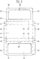
- FIG. 6 shows a plan view of a blank for a box according to a third embodiment of the invention, which is suitable, for example, as a stable and decorative box of chocolates.
- the blank 41 - 53 in turn consists of a single, flat piece of cardboard, which is formed by punching or cutting out a larger piece of cardboard, perforation or crease lines (shown in broken lines or dash-dotted lines) being pre-punched, which fold lines and / or tear lines for the Form the box to be formed.
- the blank comprises an outer top wall section 41 with end straps 42, a first strap section 43, a first side wall section 44 with end straps 45, a second strap section 46, a bottom wall section 47 with end straps 48, a third strap section 49, a second side wall section 50 with end straps 51, a fourth tab section 52 and an inner upper wall section 53.
- the various sections with their end tabs are foldably connected to one another via crease and perforation lines, as shown in FIG. 6.
- the outer upper wall section 41 has a movable cover part 54.
- the inner upper wall section 53 has a support edge 56 for the cover part 54 which delimits an opening 55.
- the cover part 54 is provided with a sealing lip 57 and the support edge 56 with a corresponding sealing slot 58.
- the blank is again folded and fixed in a manner similar to that described above in connection with FIGS. 1 and 2.
- the outer and inner upper wall sections 41 and 53 are glued together again. Now, however, not only two but four projecting tabs 59 (see FIGS. 7 and 8 in particular) are formed.
- the tab portions 46 and 49 are folded together with the bottom wall portion 47, the tab portion 43 is folded with the outer upper wall portion 41, and the tab portion 52 is folded with the inner upper wall portion 53 to form the protruding tabs 59.
- FIG. 7 shows a schematic plan view of a box according to the third embodiment of the invention with the lid 54 closed
- FIG. 8 shows a perspective view of the box according to the third embodiment of the invention with the lid 54 open.
- the outer upper wall section 41 forms, together with the inner upper wall section 53, the upper wall of the box with the lid 54. With the lid 54 open, the user has access to the contents of the box through the discharge opening 55.
- the box is essentially cuboid and in turn can be formed by simply folding and fixing it from the one-piece, pre-punched blank 41-53.
- Two opposite surfaces 41, 47 are each provided with a tab 59 lying in the plane of the respective surface 41, 47 on two parallel edges.
- these tabs 59 can be realized without any additional consumption of material and adhesive and while maintaining the inexpensive manufacture of the box. They significantly increase the stability of the box and also have a decorative effect.
- the embodiment described with reference to FIGS. 6 to 8 can advantageously be used as a decorative box, for example for chocolates.
- the supporting edge 56 for the lid part 54, together with the sealing lip 57 and the corresponding sealing slot 58, ensures the reliable closing of the box, even after it has been opened repeatedly.
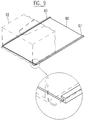
- FIG. 9 shows a perspective view of a fastening device for a box according to the invention.
- the boxes of the first and second embodiments can be attached very advantageously to such a fastening device with the aid of the tabs.
- the fastening device comprises a plate 60 with two parallel guide or holding grooves 61 with a U-shaped cross section for receiving the tabs of the box 62 shown in dashed lines.
- the part shown on an enlarged scale illustrates the guide of the tab in the groove 61.
- the flaps of the box allow them to be easily and quickly attached to the plate 60.
- No expensive housing is required.
- the plate 60 can, in a manner known per se, be fastened in a cupboard, on a wall or on another piece of furniture by means of screws or adhesive, not shown.
- the plate 60 can be made of stainless sheet, anodized aluminum, plastic, wood, etc.
- the dimensions of the plate 60 of course correspond to those of the box 62 to be used.
- a plurality of pairs of grooves 61 can also be provided on a plate for different packaging formats and filling goods. When the box 62 is not in use, there is no protruding, space-wasting housing. An empty package 62 can be replaced very quickly and easily.
- the fastening device comprises at least two parallel rail pieces for receiving the tabs of the box. This results in an even more economical and space-saving fastening device.
- the rail pieces or holding grooves can already be integrated in the manufacture of mirror cabinets, kitchen furniture, bathroom furniture and the like.
- FIG. 10 shows a perspective view of a further fastening device for a box according to the invention.
- This embodiment is even less expensive and moreover less visually striking. It comprises four short, parallel rail sections 63 for receiving the respective tab ends of the box to be fastened.
- the rail sections 63 are advantageously fastened to an auxiliary cardboard 64 which corresponds to the dimensions of the surface of the box to be fastened and which serves as a distance gauge.
- the rail sections 63 can be positioned very precisely on the wall, corresponding to the package width.
- the box can then be inserted. A simple assembly aid is thus implemented.
- the distance gauge 64 can of course also be used in combination with the parallel rail pieces described earlier. It is also possible to use only two rail sections 63.
- the box according to the invention can advantageously be used in the kitchen, bathroom, etc.
- Dispensing device are used, but also for example in hospitals or laboratories, for dispensing (for example) rubber gloves, hair nets, mouth guards or shoe covers, or in industry, for example for earplugs and the like. Since no housing is required, the packaging design is effective during the entire period of use and can be adapted to the environment and / or provided with relevant information. An empty box can be replaced very easily.
- the packaging and the fasteners are very inexpensive.
Abstract
Description
Die Erfindung betrifft eine Schachtel gemäss dem Oberbegriff des Patentanspruchs 1. Solche Schachteln sind bekannt und werden zum Beispiel zur Abgabe von Papiertüchern und dergleichen verwendet. Sie sind einfach und preiswert herzustellen, beispielsweise aus Karton oder Kunststoff. Die Erfindung betrifft weiterhin einen Zuschnitt zum Formen der Schachtel sowie eine Befestigungsvorrichtung für die Schachtel.The invention relates to a box according to the preamble of
Die bekannten Schachteln haben unter anderem den Nachteil, dass sie bei Verwendung von dünnem Karton nicht sehr stabil sind und dadurch nur beschränkte Anwendungsmöglichkeiten bieten. Sie werden entweder lose benutzt, wobei das Entnehmen eines im Inneren enthaltenen Gegenstandes beide Hände des Benutzers beansprucht, oder aber in teuren Spenderbehältern aus Metall oder aus Kunststoff eingelegt.The known boxes have the disadvantage, among other things, that they are not very stable when using thin cardboard and therefore offer only limited application possibilities. They are either used loosely, whereby the removal of an object contained in the interior takes up both hands of the user, or inserted in expensive dispenser containers made of metal or plastic.
Der Erfindung liegt die Aufgabe zugrunde, eine gattungsgemässe Schachtel zu schaffen, bei der, unter Beibehaltung der äusserst kostengünstigen und einfachen Herstellung, eine hohe Stabilität erreicht wird, und die zudem durch ihre einfache Befestigungsmöglichkeit einen breiten Anwendungsbereich hat.The invention has for its object to provide a generic box in which, while maintaining the extremely inexpensive and simple manufacture, a high degree of stability is achieved, and which also has a wide range of applications due to its ease of attachment.
Erfindungsgemäss wird dies durch die Merkmale des kennzeichnenden Teils des Patentanspruchs 1 erreicht. Die Laschen erhöhen nicht nur die Stabilität der Schachtel, sondern sie können auch als Hilfsmittel zur Befestigung benutzt werden. Somit kann die Schachtel einfach (beispielsweise mittels Schienen) befestigt werden, ohne dass ein teurer Spenderbehälter nötig wäre.According to the invention, this is achieved by the features of the characterizing part of
Weitere vorteilhafte Ausführungsformen gehen aus den Unteransprüchen hervor.Further advantageous embodiments emerge from the subclaims.
Nachfolgend werden einige beispielsweise Ausführungsformen der Erfindung an Hand der Zeichnung näher erläutert. Es zeigen:
- Fig. 1
- eine Draufsicht eines Zuschnitts für eine Schachtel gemäss einer ersten Ausführungsform der Erfindung,
- Fig. 2
- eine perspektivische Ansicht der Schachtel gemäss der ersten Ausführungsform der Erfindung,
- Fig. 3
- eine Draufsicht eines Zuschnitts für eine Schachtel gemäss einer zweiten Ausführungsform der Erfindung,
- Fig. 4
- eine schematische, teilweise im Schnitt dargestellte Draufsicht einer Schachtel gemäss der zweiten Ausführungsform der Erfindung,
- Fig. 5
- eine perspektivische Ansicht der Schachtel gemäss der zweiten Ausführungsform der Erfindung,
- Fig. 6
- eine Draufsicht eines Zuschnitts für eine Schachtel gemäss einer dritten Ausführungsform der Erfindung,
- Fig. 7
- eine schematische Draufsicht einer Schachtel gemäss der dritten Ausführungsform der Erfindung mit geschlossenem Deckel,
- Fig. 8
- eine perspektivische Ansicht der Schachtel gemäss der dritten Ausführungsform der Erfindung mit geöffenetem Deckel,
- Fig. 9
- eine perspektivische Ansicht einer Befestigungsvorrichtung für eine Schachtel gemäss der Erfindung, und
- Fig. 10
- eine perspektivische Ansicht einer weiteren Befestigungsvorrichtung für eine Schachtel gemäss der Erfindung.
- Fig. 1
- 2 shows a plan view of a blank for a box according to a first embodiment of the invention,
- Fig. 2
- 2 shows a perspective view of the box according to the first embodiment of the invention,
- Fig. 3
- 2 shows a plan view of a blank for a box according to a second embodiment of the invention,
- Fig. 4
- 2 shows a schematic plan view, partly in section, of a box according to the second embodiment of the invention,
- Fig. 5
- 2 shows a perspective view of the box according to the second embodiment of the invention,
- Fig. 6
- 2 shows a plan view of a blank for a box according to a third embodiment of the invention,
- Fig. 7
- 2 shows a schematic top view of a box according to the third embodiment of the invention with the lid closed,
- Fig. 8
- 2 shows a perspective view of the box according to the third embodiment of the invention with the lid open,
- Fig. 9
- a perspective view of a fastening device for a box according to the invention, and
- Fig. 10
- a perspective view of another fastening device for a box according to the invention.
Anhand der Figuren 1 und 2 wird im folgenden eine erste Ausführungsform der Erfindung beschrieben.A first embodiment of the invention is described below with reference to FIGS. 1 and 2.
Die Figur 1 zeigt eine Draufsicht eines Zuschnitts für eine Schachtel gemäss einer ersten Ausführungsform der Erfindung, welche insbesondere zur wiederholten Entnahme von Tüchern oder dergleichen geeignet ist. Der Zuschnitt 1 - 11 besteht aus einem einzigen, flachen Stück Karton, welches durch Ausstanzen oder Ausschneiden aus einem grösseren Stück Karton geformt wird, wobei Rill-, Perforations- oder Prägelinien (gestrichelt oder strichpunktiert dargestellt) vorgestanzt werden, welche Faltlinien und/oder Abreisslinien für die zu formende Schachtel bilden. Obwohl die Schachtel in diesem Beispiel aus Karton gefertigt wird, kann sie auch aus einer Kunststoffolie von geeigneter Steifigkeit oder einem ähnlichen Material geformt werden.FIG. 1 shows a plan view of a blank for a box according to a first embodiment of the invention, which is particularly suitable for the repeated removal of towels or the like. The blank 1 - 11 consists of a single, flat piece of cardboard, which is formed by punching or cutting out a larger piece of cardboard, with creasing, perforation or embossing lines (shown in broken lines or dash-dotted lines), which fold lines and / or tear lines are pre-punched for the box to be formed. Although the box is made of cardboard in this example, it can also be molded from a plastic film of suitable rigidity or a similar material.
Der Zuschnitt umfasst einen äusseren oberen Wandabschnitt 1 mit Endlaschen 2, einen ersten Seitenwandabschnitt 3 mit Endlaschen 4, einen ersten Laschenabschnitt 5, einen Bodenwandabschnitt 6 mit Endlaschen 7, einen zweiten Laschenabschnitt 8, einen zweiten Seitenwandabschnitt 9 mit Endlaschen 10 und einen inneren oberen Wandabschnitt 11.The blank comprises an outer
Die verschiedenen Abschnitte mit ihren Endlaschen sind über Rill- und Perforationslinien faltbar miteinander verbunden, wie in Figur 1 dargestellt ist.The different sections with their end flaps are foldably connected to one another via crease and perforation lines, as shown in FIG. 1.
Der äussere obere Wandabschnitt 1 weist einen ausreissbaren Streifen 12 sowie Oeffnungen 13 an dessen Enden auf. Der innere obere Wandabschnitt 11 weist einen schlitzförmigen Oeffnungsabschnitt 14, 15, 16 auf, welcher mindestens auf einem Teil seiner Länge von seitlichen, beweglichen Klappen 17 begrenzt ist. Die Klappen 17 sind längs Perforationslinien 18 mit dem inneren oberen Wandabschnitt 11 der Schachtel verbunden und definieren in geschlossener Stellung einen Schlitzbereich, welcher Schlitzabschnitte 14 etwa konstanter Breite und einen erweiterten Mittelteil 15 aufweist. An die Schlitzabschnitte 14 schliessen sich aussen zwei ausgeschnittene, sich nach aussen verengende Endabschnitte 16 an.The outer
Der äussere obere Wandabschnitt 1 und der innere obere Wandabschnitt 11 bilden zusammen die obere Wand der Schachtel (siehe Figur 2). Dazu werden die Abschnitte 1 und 11 derart aufeinander fixiert (zum Beispiel verleimt), dass der ausreissbare Streifen 12 den Oeffnungsabschnitt 14, 15, 16 abdeckt. Der innere Abschnitt 11, der die den Oeffnungsabschnitt 14, 15, 16 begrenzenden Klappen 17 aufweist, ist auf beiden Seiten (den Stirnöffnungen 13 entsprechend) mit einer durch eine Schnittlinie 19 freigeschnittenen Zunge 20 zur Erleichterung des Ausreissens des Streifens 12 versehen. Am einen oder anderen Ende des Streifens 12 kann man durch eine der Oeffnungen 13 unter seine Stirnkante greifen und den Streifen 12 zum Ausreissen erfassen. Die Zunge 20 kann beim Untergreifen des Streifens 12 nach innen ausweichen.The outer
Beim Formen der erfindungsgemässen Schachtel bestehen verschiedene Möglichkeiten. Zum Beispiel werden zuerst die verschiedenen Abschnitte mittels der Rill- und Perforationslinien derart gefaltet, dass der äussere obere Wandabschnitt 1 und der innere obere Wandabschnitt 11 überlappend aufeinander geklebt (oder sonstwie fixiert) werden können. Nach dem Klebevorgang wird das Zwischenprodukt gehalten, wobei auf die obere Wand 1, 11 und auf die Seitenwände 3, 9 Druck ausgeübt wird, so dass die Laschenabschnitte 5 und 8 am Bodenwandabschnitt 6 eingefaltet und dadurch mit demselben zusammengefaltet werden, wonach in an sich bekannter Weise die Endlaschen 4 und 10 nach innen gefaltet und die Endlaschen 2 und 7 aufeinander gefaltet und fixiert (zum Beispiel verklebt) werden. Durch das Verkleben der Endlaschen 2 und 7 werden die zwei vorstehenden Verstärkungs- und Führungslaschen 21 (siehe Figur 2) gebildet und ohne zusätzliche Verklebung in ihrer Lage fixiert.There are various possibilities for shaping the box according to the invention. For example, the various sections folded by means of the creasing and perforation lines in such a way that the outer
Bei einem anderen Formvorgang werden zuerst die Laschenabschnitte 5 und 8 gefaltet und mit dem Bodenwandabschnitt 6 verklebt. Dann werden die Seitenwandabschnitte 3 und 9 sowie die Endlaschen 4, 10 und 7 aufgerichtet und in an sich bekannter Weise verklebt. Nach dem Einfüllen des Produktes wird anschliessend die Packung verschlossen durch das Einfalten und Verkleben des äusseren und des inneren oberen Wandabschnittes 1 bzw. 11 sowie der Endlaschen 2.In another molding process, the
In der Figur 2 ist eine perspektivische Ansicht der Schachtel gemäss der ersten Ausführungsform der Erfindung nach erfolgtem Ausreissen des Streifens 12 wiedergegeben. Der äussere obere Wandabschnitt 1 bildet zusammen mit dem inneren oberen Wandabschnitt 11 die obere Wand der Schachtel. Der Streifen 12 (siehe Figur 1) wurde schon ausgerissen, so dass der Oeffnungsabschnitt 14, 15, 16 freiliegt und auch ein Teil des inneren oberen Wandabschnitts 11 sichtbar ist. Die durch die Schnittlinie 19 freigeschnittene Zunge 20 ist in der Figur 2 nicht wiedergegeben. Der Laschenabschnitt 5 ist mit dem Bodenwandabschnitt 6 zusammengefaltet und bildet die vorstehende Lasche 21. Genau so bildet der andere Laschenabschnitt 8 mit dem Bodenwandabschnitt 6 auf der anderen Seite auch eine vorstehende Lasche 21.FIG. 2 shows a perspective view of the box according to the first embodiment of the invention after the
Die Schachtel ist durch blosses Falten und Fixieren aus dem einteiligen, vorgestanzten Zuschnitt 1 - 11 fertigbar. Zumindest eine der Flächen der Schachtel (im gezeigten Beispiel der Bodenwandabschnitt 6) hat zwei parallele Kanten, welche jeweils eine vorstehende Lasche 21 aufweisen. Diese Laschen 21 sind, je nach Formvorgang, ohne jeglichen Mehrverbrauch an Material oder Klebstoff und unter Beibehaltung der kostengünstigen Herstellung der Schachtel realisierbar.The box can be made by simply folding and fixing it from the one-piece, pre-cut blank 1 - 11. At least one of the surfaces of the box (in the example shown the bottom wall section 6) has two parallel edges, each of which has a projecting
Die Laschen 21 liegen im wesentlichen in der Ebene der betreffenden Fläche (die Bodenwand 6) und laufen über die ganze Länge der jeweiligen gegenüberliegenden Kanten. Sie erhöhen die Stabilität der Schachtel, wodurch die Verpackung besser gegen mechanische Deformierung geschützt ist, was den Produkteschutz erhöht. Vor allem aber können sie vorteilhaft als Hilfsmittel zur Befestigung der Schachtel während derer Einsatz als Spender benutzt werden. So kann die Schachtel einfach (beispielsweise mittels Schienen oder einer preiswerten Befestigungsplatte mit Nuten) an einer Wand, in einem Schrank usw. befestigt werden und dient so als rasch auswechselbarer Spender, ohne dass dafür ein teurer Behälter nötig wäre. Dies wird im folgenden näher erläutert.The
Die Schachtel ist nahezu quaderförmig. Falls der obere Wandabschnitt 1, 11 und der Bodenwandabschnitt 6 die gleiche Breite haben (was produktionstechnisch zum Erhalten eines in Längsrichtung vorgeklebten und trotzdem noch zusammenklappbaren Zwischenproduktes normalerweise eine Bedingung ist), ist die Schachtel im Querschnitt senkrecht zur Längsachse nicht rechteckig, sondern leicht trapezförmig. Wird die Schachtel aus einem nicht vorgeklebten Zuschnitt direkt auf der Abpackmaschine geformt, so besteht die Möglichkeit, durch eine etwas breitere Bodenwand eine, natürlich abgesehen von den vorstehenden Laschen 21, nahezu perfekte Quaderform für die Schachtel zu erreichen.The box is almost cuboid. If the
Der schlitzförmige Oeffnungsabschnitt 14, 15, 16 dient beispielsweise zur wiederholten Entnahme von Papiertüchern, Kosmetiktüchern, Gesichtstüchlein oder dergleichen aus der Schachtel. Die symmetrischen, seitlichen Klappen 17 sind durch die Perforationslinien 18 beweglich mit dem inneren oberen Wandabschnitt 11 verbunden und definieren an ihren beiden Enden relativ enge Schlitzteile 14 zwischen praktisch parallelen Innenkanten der Klappen 17, sowie einen erweiterten, ovalen Mittelteil 15.The slit-shaped
Eine Vielzahl von Versuchen hat ergeben, dass mit der soeben beschriebenen Ausführung die problemlose Entnahme einzelner Tücher sichergestellt ist. Die beweglichen Klappen oder Lippen 17 erlauben einerseits dank dosierter Bremswirkung die problemlose Entnahme von Tüchern ohne Gefahr, dass diese reissen, oder dass mehr als ein Tuch zugleich austritt, oder aber dass das nächste Tuch so weit zurückbleibt, dass es nicht mehr ohne weiteres erfasst und entnommen werden kann. Andererseits kann die Entnahmeöffnung relativ klein bemessen sein, so dass der Inhalt der Schachtel gut gegen Staub und andere Einflüsse geschützt ist. Natürlich sind auch beidseitig mehrere, unabhängige Klappen mit unterschiedlichen Abmessungen und/oder unterschiedlicher Beweglichkeit möglich.A large number of tests have shown that the embodiment just described ensures that individual wipes can be removed without problems. The movable flaps or
Anhand der Figuren 3 bis 5 wird im folgenden eine zweite Ausführungsform der Erfindung beschrieben.A second embodiment of the invention is described below with reference to FIGS. 3 to 5.
Die Figur 3 zeigt eine Draufsicht eines Zuschnitts für eine Schachtel gemäss einer zweiten Ausführungsform der Erfindung, welche insbesondere zur Aufnahme einer Rolle mit einem aufgewickelten Folienmaterial sowie zum Abtrennen und Abgeben von Stücken dieses Materials von der in der Schachtel aufgenommenen Rolle geeignet ist. Der Zuschnitt 22 - 33 besteht wiederum aus einem einzigen, flachen Stück Karton, welches durch Ausstanzen oder Ausschneiden aus einem grösseren Stück Karton geformt wird, wobei Perforations- und Rillinien (gestrichelt oder strichpunktiert dargestellt) vorgestanzt werden, welche Faltlinien und/oder Abreisslinien für die zu formende Schachtel bilden.FIG. 3 shows a plan view of a blank for a box according to a second embodiment of the invention, which is particularly suitable for receiving a roll with a wound film material and for separating and releasing pieces of this material from the roll received in the box. The blank 22 - 33 in turn consists of a single, flat piece of cardboard, which is formed by punching or cutting out a larger piece of cardboard, with perforation and crease lines (shown in broken lines or dash-dotted lines) being pre-punched, which fold lines and / or tear lines for the Form the box to be formed.
Der Zuschnitt umfasst einen äusseren oberen Wandabschnitt 22 mit Endlaschen 23 und einer seitlichen Klebelasche 24, einen ersten Seitenwandabschnitt 25 mit Endlaschen 26, einen ersten Laschenabschnitt 27, einen Bodenwandabschnitt 28 mit Endlaschen 29, einen zweiten Laschenabschnitt 30, einen zweiten Seitenwandabschnitt 31 mit Endlaschen 32 und einen inneren oberen Wandabschnitt 33. Die verschiedenen Abschnitte mit ihren Endlaschen sind über Rill- und Perforationslinien faltbar miteinander verbunden, wie in Figur 3 dargestellt ist.The blank comprises an outer
Der äussere obere Wandabschnitt 22 weist einen ausreissbaren Streifen 34 sowie Oeffnungen 35 an dessen Stirnkanten auf. Der innere obere Wandabschnitt 33 weist einen schlitzförmigen Oeffnungsabschnitt 36 auf, welcher etwa dem ausreissbaren Streifen 34 entspricht. Die Endlaschen 26 und 32 der Seitenwandabschnitte 25 bzw. 31 sind mit zusätzlichen Prägelinien zum Bilden von Zentriernocken versehen, wie im folgenden näher erläutert wird. Der äussere obere Wandabschnitt 22 ist weiterhin mit einer Trennkante versehen, welche zum Abtrennen von Stücken eines aufgerollten Materials von einer in die Schachtel eingelegten Rolle geeignet ist. Die Trennkante wird durch eine sägezahnförmige Schnittlinie 37 gebildet, welche aus Stabilitätsgründen durch eine Anzahl von Rillstegen unterbrochen wird. Somit ist die Schneidekante aus dem Zuschnittmaterial gebildet und damit vollständig in die Verpackung integriert.The outer
Das Falten und Fixieren des Zuschnitts geschieht ähnlich wie oben in Zusammenhang mit den Figuren 1 und 2 beschrieben wurde. Der äussere und der innere obere Wandabschnitt 22 bzw. 33 werden wieder zusammengeklebt. Die seitliche Klebelasche 24 dient zur Verstärkung der Verbindung. Von den jeweils vier nahezu gleich grossen Abschnitten der Endlaschen 26 und 32 wird jeweils der Aeussere in einem seiner Breite entsprechenden Abstand vom Rand mit der Innenseite des betreffenden Seitenwandabschnittes verklebt. Nach dem Verleimen der Endlaschen 23 und 29 sind jetzt im Inneren der Schachtel Zentriernocken 38 für die Zentrierung der Rolle 40, und damit des Materialbandes in der Oeffnung 36, gebildet (siehe Figuren 4 und 5). Auch sind vorstehende Laschen 39 (siehe Figur 5) gebildet.The blank is folded and fixed in a manner similar to that described above in connection with FIGS. 1 and 2. The outer and inner
Nach erfolgtem Ausreissen des Streifens 34 wird in der oberen Wand 22, 33 eine längliche Abgabeöffnung für das aufgewickelte Material gebildet. Diese Abgabeöffnung ist parallel und in einem Abstand zur Trennkante vorgesehen. Dadurch wird ein einfaches, sauberes und vollständiges Abtrennen, auch von schmalen Streifen eines Folienmaterials, gewährleistet.After the
In der Figur 4 ist eine schematische, teilweise im Schnitt dargestellte Draufsicht und in der Figur 5 eine perspektivische Ansicht der Schachtel gemäss der zweiten Ausführungsform der Erfindung nach erfolgtem Ausreissen des Streifens 34 wiedergegeben. Der äussere obere Wandabschnitt 22 bildet zusammen mit dem inneren oberen Wandabschnitt 33 die obere Wand der Schachtel mit der länglichen Abgabeöffnung. Der Streifen 34 (siehe Figur 3) wurde schon ausgerissen, so dass ein Benutzer durch die Abgabeöffnung 36 Zugriff auf das aufgerollte Material der Rolle 40 hat.FIG. 4 shows a schematic top view, partly in section, and FIG. 5 shows a top view Perspective view of the box according to the second embodiment of the invention after
Die durch Rillstege unterbrochene, sägezahnförmige Schnittlinie 37 bildet die leicht über die Seitenwand 25 vorstehende Trennkante. Der Laschenabschnitt 27 ist mit dem Bodenwandabschnitt 28 zusammengefaltet und bildet die vorstehende Lasche 39. Genau so bildet der andere Laschenabschnitt 30 mit dem Bodenwandabschnitt 28 auf der anderen Seite auch eine vorstehende Lasche 39. Die Zentriernocken 38 zentrieren nicht nur die Rolle 40, sondern sie vermindern auch die beim Drehen der Rolle 40 an den Stirnseiten der Verpackung auftretende Reibung.The sawtooth-shaped
Die Schachtel ist wiederum durch blosses Falten und Fixieren aus dem einteiligen, vorgestanzten Zuschnitt 22 - 33 fertigbar. Zumindest eine der Flächen der Schachtel (im gezeigten Beispiel der Bodenwandabschnitt 28) hat zwei parallele Kanten, welche jeweils eine vorstehende Lasche 39 aufweisen. Diese Laschen 39 liegen im wesentlichen in der Ebene der betreffenden Fläche (die Bodenwand 28) und sind, je nach Formvorgang, ohne jeglichen Mehrverbrauch an Herstellungsmaterial und Klebstoff sowie unter Beibehaltung der kostengünstigen Herstellung der Schachtel realisierbar. Sie erhöhen die Stabilität der Schachtel und können vorteilhaft als Hilfsmittel zur Befestigung der Schachtel während derer Benützung als Spender verwendet werden.The box can in turn be made by simply folding and fixing it from the one-piece, pre-punched blank 22 - 33. At least one of the surfaces of the box (in the example shown the bottom wall section 28) has two parallel edges, each of which has a projecting
Die anhand der Figuren 3 bis 5 beschriebene Ausführungsform ist als Abgabeeinrichtung beispielsweise in der Küche verwendbar, für Haushaltpapier, Aluminiumfolie, Frischhaltefolie, Backtrennpapier, Gefrierbeutel oder dergleichen.The embodiment described with reference to Figures 3 to 5 is as a dispensing device, for example in the kitchen usable for household paper, aluminum foil, cling film, baking paper, freezer bags or the like.
Anhand der Figuren 6 bis 8 wird im folgenden eine dritte Ausführungsform der Erfindung beschrieben.A third embodiment of the invention is described below with reference to FIGS. 6 to 8.
Die Figur 6 zeigt eine Draufsicht eines Zuschnitts für eine Schachtel gemäss einer dritten Ausführungsform der Erfindung, welche zum Beispiel als stabile und dekorative Pralinenschachtel geeignet ist. Der Zuschnitt 41 - 53 besteht wiederum aus einem einzigen, flachen Stück Karton, welches durch Ausstanzen oder Ausschneiden aus einem grösseren Stück Karton geformt wird, wobei Perforations- oder Rillinien (gestrichelt oder strichpunktiert dargestellt) vorgestanzt werden, welche Faltlinien und/oder Abreisslinien für die zu formende Schachtel bilden.FIG. 6 shows a plan view of a blank for a box according to a third embodiment of the invention, which is suitable, for example, as a stable and decorative box of chocolates. The blank 41 - 53 in turn consists of a single, flat piece of cardboard, which is formed by punching or cutting out a larger piece of cardboard, perforation or crease lines (shown in broken lines or dash-dotted lines) being pre-punched, which fold lines and / or tear lines for the Form the box to be formed.
Der Zuschnitt umfasst einen äusseren oberen Wandabschnitt 41 mit Endlaschen 42, einen ersten Laschenabschnitt 43, einen ersten Seitenwandabschnitt 44 mit Endlaschen 45, einen zweiten Laschenabschnitt 46, einen Bodenwandabschnitt 47 mit Endlaschen 48, einen dritten Laschenabschnitt 49, einen zweiten Seitenwandabschnitt 50 mit Endlaschen 51, einen vierten Laschenabschnitt 52 und einen inneren oberen Wandabschnitt 53. Die verschiedenen Abschnitte mit ihren Endlaschen sind über Rill- und Perforationslinien faltbar miteinander verbunden, wie in Figur 6 dargestellt ist.The blank comprises an outer
Der äussere obere Wandabschnitt 41 weist einen beweglichen Deckelteil 54 auf. Der innere obere Wandabschnitt 53 weist einen eine Oeffnung 55 begrenzenden Abstützrand 56 für den Deckelteil 54 auf. Der Deckelteil 54 ist mit einer Verschlusslippe 57 und der Abstützrand 56 mit einem entsprechenden Verschlussschlitz 58 versehen.The outer
Das Falten und Fixieren des Zuschnitts geschieht wiederum ähnlich wie oben in Zusammenhang mit den Figuren 1 und 2 beschrieben wurde. Der äussere und der innere obere Wandabschnitt 41 bzw. 53 werden wieder zusammengeklebt. Jetzt werden aber nicht nur zwei, sondern vier vorstehende Laschen 59 (siehe Figuren 7 und insbesondere 8) gebildet. Die Laschenabschnitte 46 und 49 sind mit dem Bodenwandabschnitt 47 zusammengefaltet, der Laschenabschnitt 43 ist mit dem äusseren oberen Wandabschnitt 41 zusammengefaltet und der Laschenabschnitt 52 ist mit dem inneren oberen Wandabschnitt 53 zusammengefaltet zur Bildung der vorstehenden Laschen 59.The blank is again folded and fixed in a manner similar to that described above in connection with FIGS. 1 and 2. The outer and inner
In der Figur 7 ist eine schematische Draufsicht einer Schachtel gemäss der dritten Ausführungsform der Erfindung mit geschlossenem Deckel 54 und in der Figur 8 eine perspektivische Ansicht der Schachtel gemäss der dritten Ausführungsform der Erfindung mit geöffenetem Deckel 54 dargestellt. Der äussere obere Wandabschnitt 41 bildet zusammen mit dem inneren oberen Wandabschnitt 53 die obere Wand der Schachtel mit dem Deckel 54. Der Benutzer hat bei geöffnetem Deckel 54 durch die Abgabeöffnung 55 Zugriff auf den Inhalt der Schachtel.FIG. 7 shows a schematic plan view of a box according to the third embodiment of the invention with the
Die Schachtel ist im wesentlichen quaderförmig und wiederum durch blosses Falten und Fixieren aus dem einteiligen, vorgestanzten Zuschnitt 41 - 53 formbar. Zwei gegenüberliegende Flächen 41, 47 sind an je zwei parallelen Kanten mit einer in der Ebene der jeweiligen Fläche 41, 47 liegenden Lasche 59 versehen. Diese Laschen 59 sind, je nach Formvorgang, ohne jeglichen Mehrverbrauch an Material und Klebstoff sowie unter Beibehaltung der kostengünstigen Herstellung der Schachtel realisierbar. Sie erhöhen die Stabilität der Schachtel erheblich und wirken zudem dekorativ.The box is essentially cuboid and in turn can be formed by simply folding and fixing it from the one-piece, pre-punched blank 41-53. Two
Die anhand der Figuren 6 bis 8 beschriebene Ausführungsform ist vorteilhaft als dekorative Schachtel, beispielsweise für Pralinen, verwendbar. Der Abstützrand 56 für den Deckelteil 54 gewährleistet, zusammen mit der Verschlusslippe 57 und dem entsprechenden Verschlussschlitz 58, das zuverlässige Verschliessen der Schachtel, auch nach wiederholtem Oeffnen derselben.The embodiment described with reference to FIGS. 6 to 8 can advantageously be used as a decorative box, for example for chocolates. The supporting
Die Figur 9 zeigt eine perspektivische Ansicht einer Befestigungsvorrichtung für eine Schachtel gemäss der Erfindung. Insbesondere die Schachteln der ersten und zweiten Ausführungsform sind mit Hilfe der Laschen sehr vorteilhaft an einer solchen Befestigungsvorrichtung zu befestigen. Im gezeigten Beispiel umfasst die Befestigungsvorrichtung eine Platte 60 mit zwei parallelen, im Querschnitt U-förmigen Führungs- oder Haltenuten 61 zum Aufnehmen der Laschen der gestrichelt dargestellten Schachtel 62. Der vergrössert dargestellte Teil illustriert die Führung der Lasche in der Nut 61.FIG. 9 shows a perspective view of a fastening device for a box according to the invention. In particular, the boxes of the first and second embodiments can be attached very advantageously to such a fastening device with the aid of the tabs. In the example shown, the fastening device comprises a
Die Laschen der Schachtel erlauben die einfache und schnelle Befestigung derselben an der Platte 60. Es wird kein teures Gehäuse benötigt. Die Platte 60 kann, in an sich bekannter Weise mittels nicht gezeigter Schrauben oder Klebemittel, einfach in einem Schrank, an einer Wand oder an einem sonstigen Möbel befestigt werden. Die Platte 60 kann aus rostfreiem Blech, aus eloxiertem Aluminium, aus Kunststoff, aus Holz usw. hergestellt werden. Die Abmessungen der Platte 60 entsprechen natürlich denjenigen der zu verwendenden Schachtel 62. Auch können auf einer Platte mehrere Nutenpaare 61 für verschiedene Packungsformate und Füllgüter vorgesehen sein. Bei Nichtgebrauch der Schachtel 62 hat man kein vorstehendes, platzverschwendendes Gehäuse. Eine leere Verpackung 62 kann sehr schnell und einfach ausgewechselt werden.The flaps of the box allow them to be easily and quickly attached to the
In einer weiteren, nicht gezeigten Ausführungsform umfasst die Befestigungsvorrichtung zumindest zwei parallele Schienenstücke zum Aufnehmen der Laschen der Schachtel. Dies ergibt eine noch kostengünstigere und platzsparendere Befestigungsvorrichtung. Die Schienenstücke oder Haltenuten können schon bei der Herstellung von Spiegelschränken, Küchenmöbeln, Badezimmermöbeln und dergleichen integriert werden.In a further embodiment, not shown, the fastening device comprises at least two parallel rail pieces for receiving the tabs of the box. This results in an even more economical and space-saving fastening device. The rail pieces or holding grooves can already be integrated in the manufacture of mirror cabinets, kitchen furniture, bathroom furniture and the like.
Die Figur 10 zeigt eine perspektivische Ansicht einer weiteren Befestigungsvorrichtung für eine Schachtel gemäss der Erfindung. Diese Ausführungsform ist sogar noch kostengünstiger und zudem optisch weniger auffallend. Sie umfasst vier kurze, parallele Schienenteilstücke 63 zur Aufnahme der jeweiligen Laschenenden der zu befestigenden Schachtel. Vorteilhaft sind die Schienenteilstücke 63 an einem den Abmessungen der zu befestigenden Fläche der Schachtel entsprechenden Hilfskarton 64 befestigt, welcher als Distanzlehre dient. Auf diese Weise können die Schienenteilstücke 63 sehr genau, entsprechend der Packungsbreite, an der Wand positioniert werden. Nach dem Herausziehen des Hilfskartons 64 kann die Schachtel dann eingeschoben werden. Somit ist eine einfache Montagehilfe realisiert. Die Distanzlehre 64 kann natürlich auch in Kombination mit den früher beschriebenen, parallelen Schienenstücken verwendet werden. Auch ist es möglich, nur zwei Schienenteilstücke 63 zu verwenden.FIG. 10 shows a perspective view of a further fastening device for a box according to the invention. This embodiment is even less expensive and moreover less visually striking. It comprises four short,
Obwohl nur quaderförmige Schachteln beschrieben sind, ist die Erfindung keineswegs auf solche beschränkt. Auch ist als Grundform beispielsweise ein dreiseitiges Prisma möglich, sofern die Schachtel, ausgehend vom flachen Zuschnitt, auf der Abpackmaschine geformt wird.Although only rectangular boxes are described, the invention is by no means restricted to such boxes. A three-sided prism is also possible, for example, as long as the box is formed on the packaging machine, starting from the flat blank.
Die erfindungsgemässe Schachtel kann, wie schon oben beschrieben, vorteilhaft in Küche, Badezimmer usw. als Spendevorrichtung eingesetzt werden, aber auch zum Beispiel in Spitälern oder Labors, zur Abgabe von (zum Beispiel) Gummihandschuhen, Haarnetzen, Mundschutzen oder Schuhüberziehern, oder auch in der Industrie, beispielsweise für Gehörschutzpropfen und dergleichen. Da kein Gehäuse benötigt wird, kommt die Verpackungsgestaltung dabei während der ganzen Verwendungszeit zur Geltung und kann der Umgebung angepasst und/oder mit relevanten Informationen versehen werden. Eine leere Schachtel kann sehr einfach ausgewechselt werden. Die Verpackung und die Befestigungsmittel sind sehr kostengünstig.As already described above, the box according to the invention can advantageously be used in the kitchen, bathroom, etc. Dispensing device are used, but also for example in hospitals or laboratories, for dispensing (for example) rubber gloves, hair nets, mouth guards or shoe covers, or in industry, for example for earplugs and the like. Since no housing is required, the packaging design is effective during the entire period of use and can be adapted to the environment and / or provided with relevant information. An empty box can be replaced very easily. The packaging and the fasteners are very inexpensive.
Claims (20)
Priority Applications (2)
| Application Number | Priority Date | Filing Date | Title |
|---|---|---|---|
| EP19960810264 EP0803448B1 (en) | 1996-04-25 | 1996-04-25 | Kit composed of a box and a fixing device for the box |
| DE59603067T DE59603067D1 (en) | 1996-04-25 | 1996-04-25 | Set consisting of a box and a fastening device for the box |
Applications Claiming Priority (1)
| Application Number | Priority Date | Filing Date | Title |
|---|---|---|---|
| EP19960810264 EP0803448B1 (en) | 1996-04-25 | 1996-04-25 | Kit composed of a box and a fixing device for the box |
Publications (2)
| Publication Number | Publication Date |
|---|---|
| EP0803448A1 true EP0803448A1 (en) | 1997-10-29 |
| EP0803448B1 EP0803448B1 (en) | 1999-09-15 |
Family
ID=8225595
Family Applications (1)
| Application Number | Title | Priority Date | Filing Date |
|---|---|---|---|
| EP19960810264 Expired - Lifetime EP0803448B1 (en) | 1996-04-25 | 1996-04-25 | Kit composed of a box and a fixing device for the box |
Country Status (2)
| Country | Link |
|---|---|
| EP (1) | EP0803448B1 (en) |
| DE (1) | DE59603067D1 (en) |
Cited By (2)
| Publication number | Priority date | Publication date | Assignee | Title |
|---|---|---|---|---|
| WO2003013983A1 (en) * | 2001-08-08 | 2003-02-20 | Top & Twel B.V. | Dispenser and method for measured removal of foil material, and blank for producing such a dispenser |
| US7487906B2 (en) | 2006-05-05 | 2009-02-10 | Conopco, Inc. | Personal care article dispensing carton |
Citations (13)
| Publication number | Priority date | Publication date | Assignee | Title |
|---|---|---|---|---|
| GB423276A (en) * | 1934-01-24 | 1935-01-29 | Jeyes Sanitary Compounds Compa | Improvements in or relating to cartons for interleaved paper, cloth and the like |
| US2096107A (en) * | 1934-02-05 | 1937-10-19 | Harry S Haggerty | Container |
| US2324028A (en) * | 1939-12-14 | 1943-07-13 | Fibre Cord Company | Strip dispensing carton |
| US2323968A (en) * | 1942-12-05 | 1943-07-13 | Fibre Cord Company | Strip dispensing carton |
| FR1315415A (en) * | 1961-11-21 | 1963-01-18 | Cartiera Di Cairate S P A | Tank housing with self-adhesive mounting brackets for sheet elements, such as detergent papers or others |
| US3333686A (en) * | 1965-10-22 | 1967-08-01 | Fred C Schnabel | Combination dual container and suspension means therefor |
| FR1601230A (en) * | 1968-12-26 | 1970-08-10 | ||
| GB1229984A (en) * | 1968-03-26 | 1971-04-28 | ||
| DE8705198U1 (en) * | 1987-01-08 | 1987-07-16 | Reinhart, Hans, 8060 Dachau, De | |
| US4735317A (en) * | 1986-10-15 | 1988-04-05 | Nordic Industries, Inc. | Self sealing dispenser pack for pre-moistened towelettes |
| DE8906585U1 (en) * | 1989-05-30 | 1989-07-13 | Delkeskamp Kg, 4577 Nortrup, De | |
| US5141108A (en) * | 1990-10-31 | 1992-08-25 | Waldorf Corporation | Core retaining carton |
| US5219421A (en) * | 1992-06-16 | 1993-06-15 | Reid Dominion Packaging Limited | Paperboard tissue box with paperboard dispenser |
-
1996
- 1996-04-25 DE DE59603067T patent/DE59603067D1/en not_active Expired - Fee Related
- 1996-04-25 EP EP19960810264 patent/EP0803448B1/en not_active Expired - Lifetime
Patent Citations (13)
| Publication number | Priority date | Publication date | Assignee | Title |
|---|---|---|---|---|
| GB423276A (en) * | 1934-01-24 | 1935-01-29 | Jeyes Sanitary Compounds Compa | Improvements in or relating to cartons for interleaved paper, cloth and the like |
| US2096107A (en) * | 1934-02-05 | 1937-10-19 | Harry S Haggerty | Container |
| US2324028A (en) * | 1939-12-14 | 1943-07-13 | Fibre Cord Company | Strip dispensing carton |
| US2323968A (en) * | 1942-12-05 | 1943-07-13 | Fibre Cord Company | Strip dispensing carton |
| FR1315415A (en) * | 1961-11-21 | 1963-01-18 | Cartiera Di Cairate S P A | Tank housing with self-adhesive mounting brackets for sheet elements, such as detergent papers or others |
| US3333686A (en) * | 1965-10-22 | 1967-08-01 | Fred C Schnabel | Combination dual container and suspension means therefor |
| GB1229984A (en) * | 1968-03-26 | 1971-04-28 | ||
| FR1601230A (en) * | 1968-12-26 | 1970-08-10 | ||
| US4735317A (en) * | 1986-10-15 | 1988-04-05 | Nordic Industries, Inc. | Self sealing dispenser pack for pre-moistened towelettes |
| DE8705198U1 (en) * | 1987-01-08 | 1987-07-16 | Reinhart, Hans, 8060 Dachau, De | |
| DE8906585U1 (en) * | 1989-05-30 | 1989-07-13 | Delkeskamp Kg, 4577 Nortrup, De | |
| US5141108A (en) * | 1990-10-31 | 1992-08-25 | Waldorf Corporation | Core retaining carton |
| US5219421A (en) * | 1992-06-16 | 1993-06-15 | Reid Dominion Packaging Limited | Paperboard tissue box with paperboard dispenser |
Cited By (2)
| Publication number | Priority date | Publication date | Assignee | Title |
|---|---|---|---|---|
| WO2003013983A1 (en) * | 2001-08-08 | 2003-02-20 | Top & Twel B.V. | Dispenser and method for measured removal of foil material, and blank for producing such a dispenser |
| US7487906B2 (en) | 2006-05-05 | 2009-02-10 | Conopco, Inc. | Personal care article dispensing carton |
Also Published As
| Publication number | Publication date |
|---|---|
| EP0803448B1 (en) | 1999-09-15 |
| DE59603067D1 (en) | 1999-10-21 |
Similar Documents
| Publication | Publication Date | Title |
|---|---|---|
| DE60121029T2 (en) | WIPES DONATION SYSTEM | |
| EP0726205B1 (en) | Blanks for a transport and display container | |
| DE2900940A1 (en) | CARTON WITH SLIDING LID AND CUTTING FOR IT | |
| AT399701B (en) | Folding-box closure | |
| DE202007002960U1 (en) | Packaging for hygiene products | |
| DE60205929T2 (en) | CONTAINER FOR A PILE OF FOLDED PAPERWORKS | |
| EP0491399B1 (en) | Box with perforated cover | |
| EP0459110A2 (en) | Cardboard foldable box | |
| DE4023043A1 (en) | CARDBOARD FOLDING BOX | |
| EP0547424A1 (en) | Package for paper handkerchiefs | |
| EP1048577A1 (en) | Blank for package having dispenser | |
| EP0803448B1 (en) | Kit composed of a box and a fixing device for the box | |
| EP0680896B2 (en) | Soft sheet package | |
| EP0905032A1 (en) | Blank and container therefrom as well as manufacturing apparatus therefor | |
| EP3044147A1 (en) | Film dispenser and cutting blade | |
| EP0444444A1 (en) | Folding box, especially for the packaging of hygienic products | |
| DE10043850A1 (en) | Folding box with a bottom offset in the box | |
| DE60004774T2 (en) | Box with two staggered dispensing openings | |
| EP0114318A2 (en) | Folding carton | |
| EP0423754B1 (en) | Dispatch and sales container | |
| DE19842262A1 (en) | Packet or container with opening closed by inner and outer lid flap | |
| AT404350B (en) | ROLE OF RELATED SECTIONS AND DISPENSER FOR ROLLS OF THIS | |
| DE4222531A1 (en) | Carton section for forming folding box for bulk material - has section formed over tear line which in assembled state of box is on the inside and after opening of box forms measuring cup | |
| DE2920127A1 (en) | PACKING BOX | |
| DE102005018669A1 (en) | Paper board container for storage and transporting of e.g. detergents, has auxiliary clip designed as one-piece with one of segments and turned-down in direction of inner area of container, where closing clip is arranged at auxiliary clip |
Legal Events
| Date | Code | Title | Description |
|---|---|---|---|
| PUAI | Public reference made under article 153(3) epc to a published international application that has entered the european phase |
Free format text: ORIGINAL CODE: 0009012 |
|
| AK | Designated contracting states |
Kind code of ref document: A1 Designated state(s): CH DE FR LI |
|
| 17P | Request for examination filed |
Effective date: 19980312 |
|
| 17Q | First examination report despatched |
Effective date: 19980706 |
|
| GRAG | Despatch of communication of intention to grant |
Free format text: ORIGINAL CODE: EPIDOS AGRA |
|
| GRAG | Despatch of communication of intention to grant |
Free format text: ORIGINAL CODE: EPIDOS AGRA |
|
| GRAH | Despatch of communication of intention to grant a patent |
Free format text: ORIGINAL CODE: EPIDOS IGRA |
|
| GRAH | Despatch of communication of intention to grant a patent |
Free format text: ORIGINAL CODE: EPIDOS IGRA |
|
| GRAA | (expected) grant |
Free format text: ORIGINAL CODE: 0009210 |
|
| AK | Designated contracting states |
Kind code of ref document: B1 Designated state(s): CH DE FR LI |
|
| REG | Reference to a national code |
Ref country code: CH Ref legal event code: NV Representative=s name: AMMANN PATENTANWAELTE AG BERN Ref country code: CH Ref legal event code: EP |
|
| REF | Corresponds to: |
Ref document number: 59603067 Country of ref document: DE Date of ref document: 19991021 |
|
| ET | Fr: translation filed | ||
| PLBE | No opposition filed within time limit |
Free format text: ORIGINAL CODE: 0009261 |
|
| STAA | Information on the status of an ep patent application or granted ep patent |
Free format text: STATUS: NO OPPOSITION FILED WITHIN TIME LIMIT |
|
| 26N | No opposition filed | ||
| PGFP | Annual fee paid to national office [announced via postgrant information from national office to epo] |
Ref country code: FR Payment date: 20010420 Year of fee payment: 6 |
|
| PGFP | Annual fee paid to national office [announced via postgrant information from national office to epo] |
Ref country code: DE Payment date: 20010430 Year of fee payment: 6 Ref country code: CH Payment date: 20010430 Year of fee payment: 6 |
|
| PG25 | Lapsed in a contracting state [announced via postgrant information from national office to epo] |
Ref country code: LI Free format text: LAPSE BECAUSE OF NON-PAYMENT OF DUE FEES Effective date: 20020430 Ref country code: CH Free format text: LAPSE BECAUSE OF NON-PAYMENT OF DUE FEES Effective date: 20020430 |
|
| PG25 | Lapsed in a contracting state [announced via postgrant information from national office to epo] |
Ref country code: DE Free format text: LAPSE BECAUSE OF NON-PAYMENT OF DUE FEES Effective date: 20021101 |
|
| REG | Reference to a national code |
Ref country code: CH Ref legal event code: PL |
|
| PG25 | Lapsed in a contracting state [announced via postgrant information from national office to epo] |
Ref country code: FR Free format text: LAPSE BECAUSE OF NON-PAYMENT OF DUE FEES Effective date: 20021231 |
|
| REG | Reference to a national code |
Ref country code: FR Ref legal event code: ST |