EP0803673B1 - Gasdurchströmtes Ventil - Google Patents
Gasdurchströmtes Ventil Download PDFInfo
- Publication number
- EP0803673B1 EP0803673B1 EP97106432A EP97106432A EP0803673B1 EP 0803673 B1 EP0803673 B1 EP 0803673B1 EP 97106432 A EP97106432 A EP 97106432A EP 97106432 A EP97106432 A EP 97106432A EP 0803673 B1 EP0803673 B1 EP 0803673B1
- Authority
- EP
- European Patent Office
- Prior art keywords
- valve
- gas
- set forth
- magnetic
- fluid
- Prior art date
- Legal status (The legal status is an assumption and is not a legal conclusion. Google has not performed a legal analysis and makes no representation as to the accuracy of the status listed.)
- Expired - Lifetime
Links
Images


Classifications
-
- F—MECHANICAL ENGINEERING; LIGHTING; HEATING; WEAPONS; BLASTING
- F16—ENGINEERING ELEMENTS AND UNITS; GENERAL MEASURES FOR PRODUCING AND MAINTAINING EFFECTIVE FUNCTIONING OF MACHINES OR INSTALLATIONS; THERMAL INSULATION IN GENERAL
- F16K—VALVES; TAPS; COCKS; ACTUATING-FLOATS; DEVICES FOR VENTING OR AERATING
- F16K13/00—Other constructional types of cut-off apparatus; Arrangements for cutting-off
- F16K13/08—Arrangements for cutting-off not used
- F16K13/10—Arrangements for cutting-off not used by means of liquid or granular medium
-
- F—MECHANICAL ENGINEERING; LIGHTING; HEATING; WEAPONS; BLASTING
- F16—ENGINEERING ELEMENTS AND UNITS; GENERAL MEASURES FOR PRODUCING AND MAINTAINING EFFECTIVE FUNCTIONING OF MACHINES OR INSTALLATIONS; THERMAL INSULATION IN GENERAL
- F16K—VALVES; TAPS; COCKS; ACTUATING-FLOATS; DEVICES FOR VENTING OR AERATING
- F16K31/00—Actuating devices; Operating means; Releasing devices
- F16K31/02—Actuating devices; Operating means; Releasing devices electric; magnetic
- F16K31/06—Actuating devices; Operating means; Releasing devices electric; magnetic using a magnet, e.g. diaphragm valves, cutting off by means of a liquid
-
- Y—GENERAL TAGGING OF NEW TECHNOLOGICAL DEVELOPMENTS; GENERAL TAGGING OF CROSS-SECTIONAL TECHNOLOGIES SPANNING OVER SEVERAL SECTIONS OF THE IPC; TECHNICAL SUBJECTS COVERED BY FORMER USPC CROSS-REFERENCE ART COLLECTIONS [XRACs] AND DIGESTS
- Y10—TECHNICAL SUBJECTS COVERED BY FORMER USPC
- Y10S—TECHNICAL SUBJECTS COVERED BY FORMER USPC CROSS-REFERENCE ART COLLECTIONS [XRACs] AND DIGESTS
- Y10S137/00—Fluid handling
- Y10S137/909—Magnetic fluid valve
-
- Y—GENERAL TAGGING OF NEW TECHNOLOGICAL DEVELOPMENTS; GENERAL TAGGING OF CROSS-SECTIONAL TECHNOLOGIES SPANNING OVER SEVERAL SECTIONS OF THE IPC; TECHNICAL SUBJECTS COVERED BY FORMER USPC CROSS-REFERENCE ART COLLECTIONS [XRACs] AND DIGESTS
- Y10—TECHNICAL SUBJECTS COVERED BY FORMER USPC
- Y10T—TECHNICAL SUBJECTS COVERED BY FORMER US CLASSIFICATION
- Y10T137/00—Fluid handling
- Y10T137/206—Flow affected by fluid contact, energy field or coanda effect [e.g., pure fluid device or system]
- Y10T137/2082—Utilizing particular fluid
-
- Y—GENERAL TAGGING OF NEW TECHNOLOGICAL DEVELOPMENTS; GENERAL TAGGING OF CROSS-SECTIONAL TECHNOLOGIES SPANNING OVER SEVERAL SECTIONS OF THE IPC; TECHNICAL SUBJECTS COVERED BY FORMER USPC CROSS-REFERENCE ART COLLECTIONS [XRACs] AND DIGESTS
- Y10—TECHNICAL SUBJECTS COVERED BY FORMER USPC
- Y10T—TECHNICAL SUBJECTS COVERED BY FORMER US CLASSIFICATION
- Y10T137/00—Fluid handling
- Y10T137/206—Flow affected by fluid contact, energy field or coanda effect [e.g., pure fluid device or system]
- Y10T137/218—Means to regulate or vary operation of device
- Y10T137/2191—By non-fluid energy field affecting input [e.g., transducer]
-
- Y—GENERAL TAGGING OF NEW TECHNOLOGICAL DEVELOPMENTS; GENERAL TAGGING OF CROSS-SECTIONAL TECHNOLOGIES SPANNING OVER SEVERAL SECTIONS OF THE IPC; TECHNICAL SUBJECTS COVERED BY FORMER USPC CROSS-REFERENCE ART COLLECTIONS [XRACs] AND DIGESTS
- Y10—TECHNICAL SUBJECTS COVERED BY FORMER USPC
- Y10T—TECHNICAL SUBJECTS COVERED BY FORMER US CLASSIFICATION
- Y10T137/00—Fluid handling
- Y10T137/4456—With liquid valves or liquid trap seals
- Y10T137/4643—Liquid valves
Definitions
- the invention relates to a valve through which gas flows at least one gas inlet and at least one gas outlet according to the preamble of claims 1 and 3.
- Valves through which gas has flowed until now have one or several shut-off devices between the gas inlet and the gas outlet on, according to their location, a gas flow through allow the valve or interrupt the flow path.
- the Movable shut-off devices must be tolerated accordingly be so that no leakage currents in the shut-off position of the valve occur.
- the usual gas flow Valves are usually complex to manufacture.
- a generic valve is known from US Pat. No. 2,670,749, in which the flow of a fluid in a line through a magnetic oil is controlled. When applying a magnetic field the oil takes on a firmer state and sets it fluid flowing through it has a greater resistance opposite.
- Magnetic liquids are stable disperse systems, the modified magnetic particles of the size of a few nanometers as a dispersed phase.
- water, Hydrocarbons or vacuum and dispersion oils are used become.
- By deliberately changing the chemical Composition are different magnetic liquids producible based on a particular purpose can be optimized.
- Magnetic liquids have so far been used, for example the magneto-hydraulic separation, in which the magnetically conditioned, from the density and the magnetic field gradient dependent buoyancy of non-metals in the magnetic Liquid used to separate non-metals becomes.
- magnetic liquids too for the sealing, storage, damping and relief of Waves used.
- Magnetic liquids are used in automotive engineering et al for setting different damping of Vehicles because different degrees of hardness due to different large magnetic fields can be generated that different viscosities of the magnetic liquid have as a consequence.
- the object of the invention is a simple gas flow Valve with improved opening and closing effects to accomplish.
- the valve through which gas flows according to the invention operates with a movable slide body or a special one Shut-off with a magnetic liquid and is therefore very simple and very robust, since there is none Is subject to wear.
- the present invention provides the use of magnetic Liquid for switching a gas valve before, by changing the viscosity of the magnetic liquid is used by applying a magnetic field. If not or only a small magnetic field is applied, the remains magnetic liquid liquid and homogeneous. In this Condition can be a gas from the gas inlet through the liquid up flow to the gas outlet. By creating a sufficient strong magnetic field, on the other hand, goes the magnetic fluid from the liquid to the solid state in which the gas is shut off by the solidified magnetic liquid becomes.
- the magnetic fluid attracted by the magnetic field i.e. a sliding magnet can be used specifically for individual inlets or outlets to lock or open. It is also conceivable, only one apply a moderately strong magnetic field through which the magnetic Liquid does not completely shut off the gas flow and allowed a partial gas passage, so that the through amount of gas flowing through the valve according to the invention can be continuously adjusted.
- the magnetic liquid non-magnetic particles e.g. Plastics, rubber or di- or paramagnetic Add metals such as copper or aluminum that the Support switching of the valve.
- the non-magnetic Particles can be found in the magnetic liquid one dependent on their density and the magnetic field gradient get magnetic buoyancy and are thus to the pushed the upper edge of the magnetic liquid. To the others may have particles without magnetic buoyancy be caused by the change in viscosity when applied of a magnetic field are pressed together. In any case is provided by the provision of such non-magnetic particles an accelerated and improved shut-off effect of the Valve reached.
- a second aspect of the invention are in the magnetic Liquid surfactants are present due to their Molecular structure act as a surfactant and as a wetting agent are used, with esters and fatty acids particularly suitable.
- the liquid level on the Gas inlet and gas outlet is matched that when open Gas inlet and gas outlet open the liquid from Gas is flowed through.
- the Liquid when the valve is open not gas flows through.
- the magnetic field in such a direction and strength to the magnetic Liquid acts in the area of the gas inlet and / or gas outlet is displaced so that gas without flowing through the liquid directly from the gas inlet to the gas outlet can flow.
- the magnetic field attracts the liquid or repels it, thus displacing the magnetic fluid can be that it is not a horizontal, but a has an inclined liquid surface.
- the valve according to the invention can e.g. a 2/2-way valve his.
- One embodiment of the invention further provides that between the gas inlet and the gas outlet a pressure vessel is provided, which is at least partially with the magnetic Liquid is filled into which an inlet pipe protrudes, with part of the inlet pipe above the liquid level extends. By looking at the fluid level extending portion of the inlet pipe will leak the liquid from the pressure vessel via the gas-carrying Avoided inlet pipe.
- the inlet pipe can be curved and with protrude into the liquid from its inlet end or also from below through a base and a section of the pressure vessel filled with liquid to above the liquid level and from there again extend down into the liquid. Beyond that it is possible to pass the inlet pipe through a top of the pressure vessel to lead into the liquid.
- the pressure vessel is preferably cylindrical or cuboid trained and can with a rounded base be provided, the gas outlet in one embodiment is provided at the top of the pressure vessel.
- the magnetic field can be generated in different ways.
- a magnetic Liquid can be moved to and from this permanent magnet be provided according to a preferred embodiment for example, surrounds the pressure vessel in a ring and parallel to their lateral surface from an unactuated in an actuated position is displaceable.
- the actuated Position encloses the permanent magnet with the magnetic Liquid-filled part of the pressure vessel at least partially.
- Is the permanent magnet on the outer surface of the pressure vessel movable can be a separate construction with parallel guides to move the permanent magnet.
- the second way to create a magnetic field is that Providing a switchable electromagnet.
- the electromagnet too preferably encloses the one with magnetic Liquid-filled part of the pressure vessel at least partially. So inside the coil of the electromagnet, where the magnetic field is particularly strong, also the magnetic one Liquid arranged.
- a valve with a rounded lower part can the magnet that works both as a permanent magnet and as a Electromagnet can be designed continuously or in several positions can be arranged lockable to targeted the gas flow in one or more suitably arranged Interrupt or allow inlets or outlets.
- a magnetic liquid for a gas flow Valve is not just a one-way valve limited, but are also a gas flow through the invention 3/2-way and multi-way valves created by several previously described valves corresponding to each other be connected.
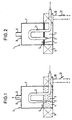
- FIGS. 1 to 4 show a valve 1 through which gas flows, which is designed as a 2/2-way valve.
- a cylindrical pressure vessel 7 is provided, which partially with a magnetic liquid 3 is filled. Outside the pressure vessel 7 surrounds an electromagnet 9 in the form of a coil filled with liquid Part of the pressure vessel 7.
- the electromagnet 9 is over Lines 10 connected to a voltage source, the Connection established depending on the position of a switch 12 or can be interrupted.
- the cylindrical shape of the pressure vessel allows a technically simple execution of the valve 1 together with its electromagnet 9, which is the pressure vessel 7 encloses in a ring and adjoins it.
- An inlet pipe 11 extends through an opening in the Shell surface of the pressure vessel 7 in the magnetic liquid 3 and further arc-shaped above the liquid level 5, to finally with its gas inlet 2 from above into the Liquid 3 to protrude. The fact that part of the inlet pipe 11 rises above the liquid level 5, none magnetic liquid 3 through the inlet pipe 11 from the Flush out pressure vessel 7. A gas outlet 6 is on the top 8 of the pressure vessel 7.
- the switch 12 is open Condition, that is, that the electromagnet 9 is not connected to the Voltage source is connected and no magnetic field is generated.
- the magnetic liquid 3 is in this state in the liquid phase before, with non-magnetic particles 4 are finely distributed in the magnetic liquid 3.
- a dispersion carrier for the existing magnetic particles water is used in the magnetic liquid 3. Since the magnetic liquid 3 according to Figure 1 in its liquid phase, gas can flow through the inlet pipe 11 and flow the gas inlet 2 through the liquid 3.
- the Area of the interior of the pressure vessel 7 that is not with Liquid 3 is filled with gas, which can flow to a consumer via the gas outlet 6.
- valve 1 If valve 1 is to be closed, the switch must also be closed 12, as shown in Figure 2, are closed so that the Electromagnet 9 generates a magnetic field which is related to the magnetic Liquid 3 works.
- the magnetic field is like this strong that a change in viscosity of the magnetic liquid 3 and a phase transition from liquid to solid takes place.
- the existing in the magnetic liquid 3 non-magnetic particles, preferably in the form of elastomers, are chosen such that they have one in this state get magnetic buoyancy in the liquid 3 and on the liquid level 5 pushed and compressed there where they form an additional barrier.
- the solidified magnetic liquid 3 does not allow flow through of gas and completely stops the gas flow.
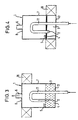
- FIG. 3 and 4 corresponds essentially to the previously explained embodiment, however, instead of the electromagnet 9 a Permanent magnet 19 is provided on the outer surface of the pressure vessel 7 is arranged to be vertically displaceable, so that the outer surface is the storage for the permanent magnet 19 represents.
- the inlet pipe 11 extends to the above-described embodiment from below by a Base 13 of the pressure vessel 7 in its interior.
- valve 1 In the open position of valve 1 shown in FIG. 3 is the permanent magnet 19 in the upper region of the pressure vessel 7 arranged.
- the magnetic field generated by him is there so far from the magnetic liquid 3 that it is too weak to be present in the liquid phase in FIG. 3 To transfer liquid 3 into the solid phase or to pull them into areas with a stronger magnetic field.
- valves 1 in which electromagnets 9 and additionally permanent magnets 19 are present are.
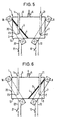
- FIGS. 5 and 6 show a valve 1 through which gas flows, which is designed as a 3/2-way valve.
- a cylindrical pressure vessel 7 provided, partially with a magnetic Liquid 3 is filled.
- a magnetic liquid 3 protrude from above through openings in the top 8 of the Pressure vessel 7, an inlet pipe 11 with a gas inlet 2 and a vent pipe 14 into it.
- a gas outlet 6 is located on the top 8 of the pressure vessel 7.
- 5 is the circuit of the Electromagnet 16 closed, i.e. the electromagnet 16 generates a magnetic field that the magnetic liquid 3 pulls into the area of the gas inlet 23 and from there the liquid phase changes to the solid phase.
- Fig. 2 Also in this Fall as in Fig. 2 are those distributed in the liquid phase non-magnetic particles 4 from the magnetic field outside, i.e. to the surface of the liquid caused by the sloping liquid level 5 is shown, crowded where they form an additional barrier.
- the solidified magnetic liquid 3 does not allow flow through of gas and seals the vent pipe 14 completely from. The gas can flow freely between the inlet pipe 11 and the gas outlet 6 flow, valve 1 is open.
- the circuit is in the position shown in FIG. 6 of the electromagnet 9 closed via the switch 12, whereas the circuit of the electromagnet 16 through the switch 21 is interrupted.
- the electromagnet 9 generates a Magnetic field that the magnetic liquid 3 in the area of the gas inlet 2 pulls so that it there from the liquid goes into the solid phase.
- As in the one shown in FIG Circuit position there is also the junction from non-magnetic particles 3.
- the gas inflow through the Inlet pipe 11 is completely interrupted, valve 1 is closed. Between gas outlet 6 and vent pipe 14 but gas can flow through the pressure vessel 7, i.e. the valve 1 is vented.
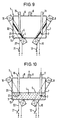
- FIGS. 7 to 10 corresponds essentially that explained in FIGS. 5 and 6 Embodiment, but instead of the vent pipe 14 a second inlet pipe 15 from above into the magnetic Liquid 3 protrudes.
- the two inlet pipes 11, 15 can alternate through one respectively assigned magnetic field closed or opened or switched together. It arises a valve 1 with a mixing function.
- Fig. 8 shows the reverse function. In this case it is Inlet tube 11 by the action of the magnetic field of the electromagnet 9 closed and between the inlet pipe 15 and gas outlet 6 gas can flow freely.
- switches 12 and 21 are open, i.e. the Electromagnets 9 and 16 do not generate magnetic fields.
- the magnetic liquid 3 is in the liquid phase and leaves gases from both gas inlets 2, 23 to gas outlet 6 stream.
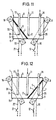
- FIGS 11 to 14 show an embodiment which in essential to the embodiment shown in Figures 7 to 10 equivalent.
- the changed arrangement creates a valve 1 with a distributor function.
- the inlet pipe 11 is arranged between two outlet pipes 17, 18, so that if there is no magnetic field, the gas inlet 2 and ends 24 and 25 of the outlet pipes 17 and 18 protrude into the magnetic liquid 3.
- Fig. 11 is the circuit by closing the switch 21 of the electromagnet 16 closed.
- the circuit of the Electromagnet 9 is open.
- the electromagnet 16 generates a magnetic field in the area of the end 24.
- the effect of the magnetic field becomes the magnetic liquid 3 pulled into this area and solidifies there.
- the above internal processes completely seal the gas outlet 17 off, whereas gas from the inlet pipe 11 without magnetic To have to flow liquid out of the outlet pipe 18 the pressure vessel 7 can flow.
- Fig. 12 shows the reverse function of the valve 1.
- the magnetic field generated by the electromagnet 9 Exhaust pipe 18 shut off. From the inlet pipe 11 gas can the outlet pipe 17 flow out of the pressure vessel 7.
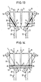
- Fig. 13 the switches 12 and 21 are closed.
- the Electromagnets 9 and 16 generate magnetic fields that are magnetic Liquid 3 in the areas of the ends 24 and 25 pull and this goes into the solid phase.
- the two Outlet pipes 17 and 18 are described by those already described internal processes in the magnetic liquid 3 completely shut off, valve 1 is in the locking function.
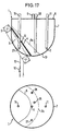
- FIGS. 15 and 16 show a further embodiment of a valve 1, which is a multi-way valve with a mixing function is formed and four inlet pipes 11, 15, 26 and 27 and has a gas outlet 6. Operation of the valve 1 corresponds essentially to that in FIGS. 7 to 10 explained valve 1.
- Shutting off or opening individual Inlet pipes 11, 15, 26, 27 are made by means of the electromagnet 9, which on the hemispherical lower part 13 'of Valve 1 about the vertical longitudinal axis of the pressure vessel 7 horizontally (see arrow A) rotatable and / or around the lower one Pendulum end of the hemispherical part 13 '(see arrow B) is displaceable.
- the corresponding guidance of the electromagnet 9 is not shown.
- the electromagnet 9 is in multiple positions or even infinitely lockable.
- the electromagnet 9 can also be a permanent magnet be provided.
- the annular electromagnet 9 by a Guide, not shown, slidably mounted that its magnetic field only reaches the area of a gas inlet 2. Due to the effect of the magnetic field, the frozen one locks Magnetic liquid 3 from the inlet pipe 15. Becomes the liquid level 5 by refilling liquid 3 via a filler tube, not shown, to the liquid level 5a brought, depending on the liquid level 5a the magnetic liquid 3 and the position of the electromagnet 9 further inlet pipes blocked, in the example the Inlet pipes 26 and 27.
- FIGS. 17 and 18 show the valve 1 through which gas flows as has already been explained with reference to FIGS. 15 and 16 is.
- a gas sealable Filler tube 28 from above through the top 8 of the pressure vessel 7 so far down that it is in the horizontal basic position of the magnet 9 in the magnetic Liquid 3 protrudes.
- the filler tube 28 is with a Pump system, not shown, connected and enables Constant function change of the valve 1.
- a Pump system not shown
- reusable valves are characterized by that they get by with a single pressure vessel, because the magnetic fluid in a strong magnetic field is drawn in so that certain inlet or outlet pipes can be opened or closed. Furthermore, reusable valves can be replaced by several of the valves described above arise, which have corresponding Drilling lines are connected and switched.
- a potentiometer can be placed in front of each switch 12, 21 be arranged, through which the electromagnet 9th applied current are continuously changed can.
- the current strength changes again the viscosity of the magnetic liquid 3, so that the viscosity of the magnetic liquid 3 is continuously adjustable and more or less gas through valve 1 flows. This results in a continuously adjustable valve.
Description
- Figur 1 eine schematische Darstellung eines erfindungsgemäßen, mit einem Elektromagneten ausgestatteten 2/2-Wege-Ventils in geöffnetem Zustand,
- Figur 2 das Ventil nach Figur 1 in geschlossenem Zustand,
- Figur 3 eine schematische Darstellung des erfindungsgemäßen, mit einem Permanentmagneten ausgestatteten 2/2-Wege-Ventils gemäß einer zweiten Ausführungsform in geöffnetem Zustand,
- Figur 4 das Ventil nach Figur 3 in geschlossenem Zustand,
- Figur 5 eine schematische Darstellung eines erfindungsgemäßen, mit zwei Elektromagneten ausgestatteten 3/2-Wege-Ventils in geöffnetem Zustand,
- Figur 6 das Ventil nach Figur 5 in geschlossenem Zustand,
- Figur 7 eine schematische Darstellung eines erfindungsgemäßen, mit zwei Elektromagneten ausgestatteten Ventils mit Mischfunktion in der Schaltstellung 1. Gaseinlaß geöffnet, 2. Gaseinlaß geschlossen,
- Figur 8 das Ventil nach Figur 7 in der umgekehrten Schaltstellung 1. Gaseinlaß geschlossen, 2. Gaseinlaß geöffnet,
- Figur 9 das Ventil nach den Figuren 7 und 8 in der Schaltstellung geschlossen,
- Figur 10 das Ventil nach den Figuren 7 bis 9 in der Schaltstellung geöffnet,
- Figur 11 eine schematische Darstellung eines erfindungsgemäßen, mit zwei Elektromagneten ausgestatteten Ventils gemäß einer weiteren Ausführungsform, mit Verteilerfunktion in der Schaltstellung 1. Gasauslaß geöffnet, 2. Gasauslaß geschlossen,
- Figur 12 das Ventil nach Figur 11 in der Schaltstellung 1. Gasauslaß geschlossen, 2. Gasauslaß geöffnet,
- Figur 13 das Ventil nach den Figuren 11 und 12 in der Schaltstellung geschlossen,
- Figur 14 das Ventil nach den Figuren 11 bis 13 in der Schaltstellung geöffnet,
- Figur 15 in Seitenansicht und Draufsicht eine schematische Darstellung eines erfindungsgemäßen, mit einem Elektromagneten ausgestatteten Mehrwege-Ventils gemäß einer zusätzlichen Ausführungsform in teilweise geschlossenem Zustand,
- Figur 16 in Seitenansicht und Draufsicht das Ventil nach Figur 15 im Zustand alle Gaseinlässe geöffnet,
- Figur 17 in Seitenansicht und Draufsicht eine schematische Darstellung eines erfindungsgemäßen, mit einem Elektromagneten ausgestatteten weiteren Mehrwege-Ventils mit einem Einfüllrohr, über das der Flüssigkeitsstand der magnetischen Flüssigkeit regelbar ist, in teilweise geschlossenem Zustand, und
- Figur 18 in Seitenansicht und Draufsicht das Ventil nach Figur 17 im Zustand alle Gaseinlässe geöffnet.
Claims (30)
- Gasdurchströmtes Ventil mit mindestens einem Gaseinlaß (2) und mindestens einem Gasauslaß (6), bei dem im Strömungsweg zwischen Gaseinlaß (2, 23) und Gasauslaß (6) im Ventil (1) eine magnetische Flüssigkeit (3) vorgesehen ist, die bei angelegtem Magnetfeld erstarrt und den Strömungsweg von mindestens einem Gaseinlaß (2, 23) zu einem oder mehreren Gasauslässen (6) gasdicht unterbricht und ohne angelegtes Magnetfeld von Gas durchströmbar ist, dadurch gekennzeichnet, daß in der magnetischen Flüssigkeit (3) nichtmagnetische Partikel (4) vorhanden sind.
- Ventil nach Anspruch 1, dadurch gekennzeichnet, daß in der magnetischen Flüssigkeit (3) para- und diamagnetische Metallpartikel und/oder als nichtmagnetische Partikel (4) Elastomere vorhanden sind.
- Gasdurchströmtes Ventil mit mindestens einem Gaseinlaß (2) und mindestens einem Gasauslaß (6), bei dem im Strömungsweg zwischen Gaseinlaß (2, 23) und Gasauslaß (6) im Ventil (1) eine magnetische Flüssigkeit (3) vorgesehen ist, die bei angelegtem Magnetfeld erstarrt und den Strömungsweg von mindestens einem Gaseinlaß (2, 23) zu einem oder mehreren Gasauslässen (6) gasdicht unterbricht und ohne angelegtes Magnetfeld von Gas durchströmbar ist, dadurch gekennzeichnet, daß in der magnetischen Flüssigkeit (3) Tenside vorhanden sind.
- Ventil nach einem der vorstehenden Ansprüche, dadurch gekennzeichnet, daß der Flüssigkeitsstand (5, 5a) so auf den Gaseinlaß (2, 23) und den Gasauslaß (6) abgestimmt ist, daß die Flüssigkeit (3) bei geöffnetem Gaseinlaß (2, 23) und geöffnetem Gasauslaß (6) von Gas durchströmt wird.
- Ventil nach einem der vorstehenden Ansprüche, dadurch gekennzeichnet, daß das Magnetfeld zum Öffnen von mindestens einem Gaseinlaß (2, 23) und/oder einem Gasauslaß (6) in einer solchen Richtung und Stärke auf die Flüssigkeit (3) einwirkt, daß diese im Bereich des Gaseinlasses (2, 23) und/oder des Gasauslasses (6) verdrängt wird, so daß Gas ohne Durchströmen der Flüssigkeit (3) direkt vom Gaseinlaß (2, 23) zum Gasauslaß (6) strömen kann.
- Ventil nach einem der vorstehenden Ansprüche, dadurch gekennzeichnet, daß das Ventil ein 2/2-Wege-Ventil ist.
- Ventil nach einem der Ansprüche 1 bis 5, dadurch gekennzeichnet, daß das Ventil ein Mehrweg-Ventil ist.
- Ventil nach einem der vorstehenden Ansprüche, dadurch gekennzeichnet, daß zwischen dem Gaseinlaß (2, 23) und dem Gasauslaß (6) ein Druckgefäß (7) vorgesehen ist, das zumindest teilweise mit der magnetischen Flüssigkeit (3) gefüllt ist, in die mindestens ein Einlaßrohr (11, 15, 26, 27) hineinragt, wobei sich ein Teil des Einlaßrohres (11, 15, 26, 27) über den Flüssigkeitsstand (5) erstreckt.
- Ventil nach Anspruch 8, dadurch gekennzeichnet, daß das Einlaßrohr (11) bogenförmig ausgebildet ist und sein Einlaßende (2) von oben her in die Flüssigkeit (3) ragt.
- Ventil nach Anspruch 9, dadurch gekennzeichnet, daß sich das Einlaßrohr (11) von unten durch eine Grundfläche (13) und einen mit magnetischer Flüssigkeit (3) gefüllten Abschnitt des Druckgefäßes (7) bis oberhalb des Flüssigkeitsstands (5) und von dort nach unten in die Flüssigkeit (3) erstreckt.
- Ventil nach Anspruch 9 oder 10, dadurch gekennzeichnet, daß sich mindestens ein Einlaßrohr (11, 15, 26, 27) von oben durch eine Oberseite (8) des Druckgefäßes (7) bis in die Flüssigkeit (3) erstreckt.
- Ventil nach einem der vorstehenden Ansprüche, dadurch gekennzeichnet, daß das Druckgefäß (7) zylindrisch oder quaderförmig ist.
- Ventil nach einem der vorstehenden Ansprüche, dadurch gekennzeichnet, daß der untere Teil (13') des Druckgefäßes (7) abgerundet ist.
- Ventil nach einem der vorstehenden Ansprüche, dadurch gekennzeichnet, daß der Gasauslaß (6) an der Oberseite (8) des Druckgefäßes (7) vorgesehen ist.
- Ventil nach Anspruch 14, dadurch gekennzeichnet, daß der Gasauslaß mindestens ein Auslaßrohr (17, 18) mit einem Ende (24, 25) umfaßt, das von oben in die magnetische Flüssigkeit (3) hineinragt.
- Ventil nach einem der vorstehenden Ansprüche, dadurch gekennzeichnet, daß ein Entlüftungsrohr (14) von oben in die magnetische Flüssigkeit (3) hineinragt.
- Ventil nach einem der vorstehenden Ansprüche, dadurch gekennzeichnet, daß ein zur magnetischen Flüssigkeit (3) hin- und von dieser wegbewegbarer Permanentmagnet (19) zum Aufbringen eines Magnetfeldes vorgesehen ist.
- Ventil nach Anspruch 17, dadurch gekennzeichnet, daß der Permanentmagnet (19) das Druckgefäß (7) ringförmig umschließt und parallel zu deren Mantelfläche (20) aus einer unbetätigten in eine betätigte Stellung verschiebbar ist, in welcher er den mit der magnetischen Flüssigkeit (3) gefüllten Teil des Druckgefäßes (7) zumindest teilweise umschließt.
- Ventil nach Anspruch 18, dadurch gekennzeichnet, daß der Permanentmagnet (19) an der Mantelfläche (20) des Druckgefäßes (7) verschiebbar ist.
- Ventil nach einem der vorstehenden Ansprüche, dadurch gekennzeichnet, daß mehrere Permanentmagnete gegenüberliegend angeordnet sind, so daß ihr Magnetfeld jeweils auf die Flüssigkeit (3) im Bereich mindestens eines Einlaßrohres (11, 15, 26, 27) oder mindestens eines Auslaßrohres (17, 18) wirkt.
- Ventil nach Anspruch 20, dadurch gekennzeichnet, daß Permanentmagnete auf einer Führung zu dem Druckgefäß hin- und von ihm wegbewegbar sind.
- Ventil nach einem der vorstehenden Ansprüche, dadurch gekennzeichnet, daß mindestens ein schaltbarer Elektromagnet (9, 19) vorgesehen ist.
- Ventil nach Anspruch 22, dadurch gekennzeichnet, daß der Elektromagnet (9, 19) den mit magnetischer Flüssigkeit (3) gefüllten Teil des Druckgefäßes (7) zumindest teilweise umschließt.
- Ventil nach Anspruch 13 und Anspruch 22 oder 23, dadurch gekennzeichnet, daß der Elektromagnet (9) am abgerundeten unteren Teil (13') des Druckgefäßes (7) verschiebbar ist.
- Ventil nach einem der Ansprüche 22 bis 24, dadurch gekennzeichnet, daß mehrere Elektromagnete (9, 16) gegenüberliegend angeordnet sind, so daß ihr Magnetfeld jeweils im Bereich mindestens eines Einlaßrohres (11) oder mindestens eines Auslaßrohres (17) wirkt.
- Ventil nach einem der Ansprüche 22 bis 25, dadurch gekennzeichnet, daß die Elektromagnete (9, 16) getrennt oder gemeinsam geschaltet werden.
- Ventil nach einem der Ansprüche 22 bis 26, dadurch gekennzeichnet, daß durch Anlegen einer stetig veränderlichen Stromstärke an den mindestens einen Elektromagneten (9, 19) die Viskosität der magnetischen Flüssigkeit (3) stetig verändert werden kann, so daß je nach Zähigkeit der magnetischen Flüssigkeit (3) mehr oder weniger Gas fließt, wodurch ein stufenlos einstellbares Ventil (1) entsteht.
- Ventil nach einem der vorstehenden Ansprüche, dadurch gekennzeichnet, daß der Flüssigkeitsstand (5, 5a) des Druckgefäßes (7) verändert werden kann.
- Ventil nach Anspruch 28, dadurch gekennzeichnet, daß über ein in die Flüssigkeit (3) von oben hineinragendes, gegen Gasdurchfluß abdichtbares Einfüllrohr (28) der Flüssigkeitsstand (5, 5a) beliebig veränderbar ist.
- Gasdurchströmtes Mehrweg-Ventil, dadurch gekennzeichnet, daß das Mehrweg-Ventil aus mehreren entsprechend miteinander verbundenen und schaltbaren gasdurchströmten Ventilen (1) nach einem der Ansprüche 1 bis 29 gebildet ist.
Applications Claiming Priority (2)
| Application Number | Priority Date | Filing Date | Title |
|---|---|---|---|
| DE29607363U DE29607363U1 (de) | 1996-04-23 | 1996-04-23 | Gasdurchströmtes Ventil |
| DE29607363U | 1996-04-23 |
Publications (3)
| Publication Number | Publication Date |
|---|---|
| EP0803673A2 EP0803673A2 (de) | 1997-10-29 |
| EP0803673A3 EP0803673A3 (de) | 1998-05-20 |
| EP0803673B1 true EP0803673B1 (de) | 2002-06-26 |
Family
ID=8023002
Family Applications (1)
| Application Number | Title | Priority Date | Filing Date |
|---|---|---|---|
| EP97106432A Expired - Lifetime EP0803673B1 (de) | 1996-04-23 | 1997-04-18 | Gasdurchströmtes Ventil |
Country Status (3)
| Country | Link |
|---|---|
| US (1) | US6044866A (de) |
| EP (1) | EP0803673B1 (de) |
| DE (2) | DE29607363U1 (de) |
Families Citing this family (10)
| Publication number | Priority date | Publication date | Assignee | Title |
|---|---|---|---|---|
| DE19816208B4 (de) * | 1998-04-09 | 2009-04-23 | Knorr-Bremse Systeme für Schienenfahrzeuge GmbH | Steuerventil |
| CA2382347A1 (fr) * | 2002-05-01 | 2003-11-01 | Autolog Inc. | Poste de classement avec zone de decision dynamique |
| US7670623B2 (en) * | 2002-05-31 | 2010-03-02 | Materials Modification, Inc. | Hemostatic composition |
| US7560160B2 (en) * | 2002-11-25 | 2009-07-14 | Materials Modification, Inc. | Multifunctional particulate material, fluid, and composition |
| US7007972B1 (en) | 2003-03-10 | 2006-03-07 | Materials Modification, Inc. | Method and airbag inflation apparatus employing magnetic fluid |
| US6982501B1 (en) | 2003-05-19 | 2006-01-03 | Materials Modification, Inc. | Magnetic fluid power generator device and method for generating power |
| US7200956B1 (en) | 2003-07-23 | 2007-04-10 | Materials Modification, Inc. | Magnetic fluid cushioning device for a footwear or shoe |
| US7448389B1 (en) | 2003-10-10 | 2008-11-11 | Materials Modification, Inc. | Method and kit for inducing hypoxia in tumors through the use of a magnetic fluid |
| WO2006113073A1 (en) * | 2005-04-12 | 2006-10-26 | E. I. Du Pont De Nemours And Company | System for accurately weighing solids and control mechanism for same |
| CA2840172A1 (en) * | 2010-06-23 | 2011-12-29 | The Greenward Company L.L.C. | Flow regulating applied magnetic envelope |
Family Cites Families (18)
| Publication number | Priority date | Publication date | Assignee | Title |
|---|---|---|---|---|
| US2670749A (en) * | 1949-07-21 | 1954-03-02 | Hanovia Chemical & Mfg Co | Magnetic valve |
| US3010471A (en) * | 1959-12-21 | 1961-11-28 | Ibm | Valve for magnetic fluids |
| US3417771A (en) * | 1965-09-24 | 1968-12-24 | Ernst Hans | Flow control apparatus for fluent magnetic materials |
| US3448751A (en) * | 1965-10-08 | 1969-06-10 | Norco Products Inc | Magnetic fluid pressure control |
| US3406704A (en) * | 1966-01-21 | 1968-10-22 | Wheelabrator Corp | Flow regulating valve for magnetic particles |
| US3701357A (en) * | 1968-09-30 | 1972-10-31 | Asea Ab | Electromagnetic valve means for tapping molten metal |
| US3982722A (en) * | 1975-11-21 | 1976-09-28 | General Motors Corporation | Magnetic control valve |
| US3970112A (en) * | 1975-12-08 | 1976-07-20 | General Motors Corporation | Control valve |
| DE2718508C3 (de) * | 1977-04-26 | 1980-12-04 | Nautschno-Issledovatelskaja Laboratorija Fiziko-Chimitscheskoj Mechaniki Materialov I Technologitscheskich Processov, Moskau | Verfahren zur Dosierung von Schüttgütern und Arbeitsorgan für eine entsprechende Dosiervorrichtung |
| DE2758072A1 (de) * | 1977-12-24 | 1979-07-05 | Teves Gmbh Alfred | Magnetventil |
| DE2839774A1 (de) * | 1978-09-13 | 1980-03-27 | Yoram Prof Dr Med Palti | Vorrichtung zur einstellung des durchflussquerschnitts eines ventils |
| JPS58672A (ja) * | 1981-06-25 | 1983-01-05 | Kiyuubitsuku Eng:Kk | 安全弁装置 |
| US4463502A (en) * | 1982-03-08 | 1984-08-07 | Fitzgerald Thomas J | Magnetic distributor-downcomer for fluidized beds and magnetic valve to control the flow of solids |
| US5075021A (en) * | 1989-09-29 | 1991-12-24 | Carlson J David | Optically transparent electrorheological fluids |
| US5032308A (en) * | 1989-11-07 | 1991-07-16 | The Dow Chemical Company | Layered mixed metal hydroxides in electrorheological fluids |
| MX170398B (es) * | 1989-11-14 | 1993-08-19 | Hylsa Sa | Metodo y aparato mejorados para regular el flujo de solidos ferromagneticos particulados |
| DE4100166A1 (de) * | 1991-01-05 | 1992-07-09 | Freudenberg Carl Fa | Druckregulierendes ent- und belueftungsventil |
| US5362027A (en) * | 1993-11-12 | 1994-11-08 | Electronics, Incorporated | Flow regulating valve for magnetic particles |
-
1996
- 1996-04-23 DE DE29607363U patent/DE29607363U1/de not_active Expired - Lifetime
-
1997
- 1997-04-18 EP EP97106432A patent/EP0803673B1/de not_active Expired - Lifetime
- 1997-04-18 DE DE59707585T patent/DE59707585D1/de not_active Expired - Fee Related
- 1997-04-18 US US08/839,809 patent/US6044866A/en not_active Expired - Fee Related
Also Published As
| Publication number | Publication date |
|---|---|
| EP0803673A2 (de) | 1997-10-29 |
| DE59707585D1 (de) | 2002-08-01 |
| DE29607363U1 (de) | 1996-08-22 |
| EP0803673A3 (de) | 1998-05-20 |
| US6044866A (en) | 2000-04-04 |
Similar Documents
| Publication | Publication Date | Title |
|---|---|---|
| EP0803673B1 (de) | Gasdurchströmtes Ventil | |
| DE19849742A1 (de) | Ventil des Membrantyps | |
| DE602005004269T2 (de) | Ventil mit magnetischer steuereinheit | |
| EP0402559A2 (de) | Umschaltarmatur | |
| EP1052441B1 (de) | Magnetisch betätigbares Ventil | |
| DE2424978A1 (de) | Rohrunterbrecher, insbesondere fuer hauswasserleitungen | |
| EP0638154B1 (de) | Ventil zur steuerung eines unter druck strömenden, fluiden mediums | |
| DE60121575T2 (de) | Hahn mit sekundärer öffnung | |
| DE3100582A1 (de) | Druck-steuerventil | |
| EP0112977A1 (de) | Absperrarmatur für aggressive Medien | |
| EP3453930B1 (de) | Ventil zur regelung eines fluids | |
| EP2000714A2 (de) | Fluid-Ventilanordnung | |
| DE2833924A1 (de) | Hydraulische schaltgruppe | |
| WO2019068278A1 (de) | Magnetorheologischer aktor mit verschlussanordnung | |
| EP0004324A2 (de) | Mehrwegeventil | |
| DE60121156T2 (de) | Magnetisch steuerbares ventil | |
| DE4203723C2 (de) | Doppelsitzventil | |
| DE3247323A1 (de) | Rohrtrenner | |
| DE643583C (de) | Kanalisationsanlage zum Abfuehren von Haushalts- und Industrieabfaellen mittels Unterdruckes | |
| EP4065508B1 (de) | Zapfventil mit auslaufschutzeinrichtung | |
| WO2019007796A1 (de) | Ventil | |
| AT405910B (de) | Magnetischer aufbereiter | |
| EP1217270A2 (de) | Hubventil | |
| AT148036B (de) | Absperrschieber. | |
| DE872295C (de) | Stroemungsmittel-Kupplung |
Legal Events
| Date | Code | Title | Description |
|---|---|---|---|
| PUAI | Public reference made under article 153(3) epc to a published international application that has entered the european phase |
Free format text: ORIGINAL CODE: 0009012 |
|
| AK | Designated contracting states |
Kind code of ref document: A2 Designated state(s): DE FR GB IT |
|
| PUAL | Search report despatched |
Free format text: ORIGINAL CODE: 0009013 |
|
| AK | Designated contracting states |
Kind code of ref document: A3 Designated state(s): DE FR GB IT |
|
| 17P | Request for examination filed |
Effective date: 19981116 |
|
| 17Q | First examination report despatched |
Effective date: 20001215 |
|
| GRAG | Despatch of communication of intention to grant |
Free format text: ORIGINAL CODE: EPIDOS AGRA |
|
| GRAG | Despatch of communication of intention to grant |
Free format text: ORIGINAL CODE: EPIDOS AGRA |
|
| GRAH | Despatch of communication of intention to grant a patent |
Free format text: ORIGINAL CODE: EPIDOS IGRA |
|
| GRAH | Despatch of communication of intention to grant a patent |
Free format text: ORIGINAL CODE: EPIDOS IGRA |
|
| GRAA | (expected) grant |
Free format text: ORIGINAL CODE: 0009210 |
|
| AK | Designated contracting states |
Kind code of ref document: B1 Designated state(s): DE FR GB IT |
|
| REG | Reference to a national code |
Ref country code: GB Ref legal event code: FG4D Free format text: NOT ENGLISH |
|
| REF | Corresponds to: |
Ref document number: 59707585 Country of ref document: DE Date of ref document: 20020801 |
|
| GBT | Gb: translation of ep patent filed (gb section 77(6)(a)/1977) |
Effective date: 20020827 |
|
| ET | Fr: translation filed | ||
| PLBE | No opposition filed within time limit |
Free format text: ORIGINAL CODE: 0009261 |
|
| STAA | Information on the status of an ep patent application or granted ep patent |
Free format text: STATUS: NO OPPOSITION FILED WITHIN TIME LIMIT |
|
| 26N | No opposition filed |
Effective date: 20030327 |
|
| PGFP | Annual fee paid to national office [announced via postgrant information from national office to epo] |
Ref country code: DE Payment date: 20050525 Year of fee payment: 9 |
|
| PGFP | Annual fee paid to national office [announced via postgrant information from national office to epo] |
Ref country code: FR Payment date: 20060410 Year of fee payment: 10 |
|
| PGFP | Annual fee paid to national office [announced via postgrant information from national office to epo] |
Ref country code: GB Payment date: 20060412 Year of fee payment: 10 |
|
| PGFP | Annual fee paid to national office [announced via postgrant information from national office to epo] |
Ref country code: IT Payment date: 20060430 Year of fee payment: 10 |
|
| PG25 | Lapsed in a contracting state [announced via postgrant information from national office to epo] |
Ref country code: DE Free format text: LAPSE BECAUSE OF NON-PAYMENT OF DUE FEES Effective date: 20061101 |
|
| GBPC | Gb: european patent ceased through non-payment of renewal fee |
Effective date: 20070418 |
|
| PG25 | Lapsed in a contracting state [announced via postgrant information from national office to epo] |
Ref country code: GB Free format text: LAPSE BECAUSE OF NON-PAYMENT OF DUE FEES Effective date: 20070418 |
|
| PG25 | Lapsed in a contracting state [announced via postgrant information from national office to epo] |
Ref country code: FR Free format text: LAPSE BECAUSE OF NON-PAYMENT OF DUE FEES Effective date: 20070430 |
|
| PG25 | Lapsed in a contracting state [announced via postgrant information from national office to epo] |
Ref country code: IT Free format text: LAPSE BECAUSE OF NON-PAYMENT OF DUE FEES Effective date: 20070418 |