EP0803691A2 - Evaporation device for refrigeration equipment - Google Patents
Evaporation device for refrigeration equipment Download PDFInfo
- Publication number
- EP0803691A2 EP0803691A2 EP97106819A EP97106819A EP0803691A2 EP 0803691 A2 EP0803691 A2 EP 0803691A2 EP 97106819 A EP97106819 A EP 97106819A EP 97106819 A EP97106819 A EP 97106819A EP 0803691 A2 EP0803691 A2 EP 0803691A2
- Authority
- EP
- European Patent Office
- Prior art keywords
- refrigeration equipment
- liquid
- heat
- evaporation
- tray forming
- Prior art date
- Legal status (The legal status is an assumption and is not a legal conclusion. Google has not performed a legal analysis and makes no representation as to the accuracy of the status listed.)
- Withdrawn
Links
Images


Classifications
-
- F—MECHANICAL ENGINEERING; LIGHTING; HEATING; WEAPONS; BLASTING
- F25—REFRIGERATION OR COOLING; COMBINED HEATING AND REFRIGERATION SYSTEMS; HEAT PUMP SYSTEMS; MANUFACTURE OR STORAGE OF ICE; LIQUEFACTION SOLIDIFICATION OF GASES
- F25D—REFRIGERATORS; COLD ROOMS; ICE-BOXES; COOLING OR FREEZING APPARATUS NOT OTHERWISE PROVIDED FOR
- F25D21/00—Defrosting; Preventing frosting; Removing condensed or defrost water
- F25D21/14—Collecting or removing condensed and defrost water; Drip trays
-
- F—MECHANICAL ENGINEERING; LIGHTING; HEATING; WEAPONS; BLASTING
- F25—REFRIGERATION OR COOLING; COMBINED HEATING AND REFRIGERATION SYSTEMS; HEAT PUMP SYSTEMS; MANUFACTURE OR STORAGE OF ICE; LIQUEFACTION SOLIDIFICATION OF GASES
- F25D—REFRIGERATORS; COLD ROOMS; ICE-BOXES; COOLING OR FREEZING APPARATUS NOT OTHERWISE PROVIDED FOR
- F25D2321/00—Details or arrangements for defrosting; Preventing frosting; Removing condensed or defrost water, not provided for in other groups of this subclass
- F25D2321/14—Collecting condense or defrost water; Removing condense or defrost water
- F25D2321/141—Removal by evaporation
- F25D2321/1411—Removal by evaporation using compressor heat
-
- F—MECHANICAL ENGINEERING; LIGHTING; HEATING; WEAPONS; BLASTING
- F25—REFRIGERATION OR COOLING; COMBINED HEATING AND REFRIGERATION SYSTEMS; HEAT PUMP SYSTEMS; MANUFACTURE OR STORAGE OF ICE; LIQUEFACTION SOLIDIFICATION OF GASES
- F25D—REFRIGERATORS; COLD ROOMS; ICE-BOXES; COOLING OR FREEZING APPARATUS NOT OTHERWISE PROVIDED FOR
- F25D2321/00—Details or arrangements for defrosting; Preventing frosting; Removing condensed or defrost water, not provided for in other groups of this subclass
- F25D2321/14—Collecting condense or defrost water; Removing condense or defrost water
- F25D2321/141—Removal by evaporation
- F25D2321/1412—Removal by evaporation using condenser heat or heat of desuperheaters
-
- F—MECHANICAL ENGINEERING; LIGHTING; HEATING; WEAPONS; BLASTING
- F25—REFRIGERATION OR COOLING; COMBINED HEATING AND REFRIGERATION SYSTEMS; HEAT PUMP SYSTEMS; MANUFACTURE OR STORAGE OF ICE; LIQUEFACTION SOLIDIFICATION OF GASES
- F25D—REFRIGERATORS; COLD ROOMS; ICE-BOXES; COOLING OR FREEZING APPARATUS NOT OTHERWISE PROVIDED FOR
- F25D2321/00—Details or arrangements for defrosting; Preventing frosting; Removing condensed or defrost water, not provided for in other groups of this subclass
- F25D2321/14—Collecting condense or defrost water; Removing condense or defrost water
- F25D2321/143—Collecting condense or defrost water; Removing condense or defrost water characterised by means to fix, clamp, or connect water pipes or evaporation trays
-
- F—MECHANICAL ENGINEERING; LIGHTING; HEATING; WEAPONS; BLASTING
- F25—REFRIGERATION OR COOLING; COMBINED HEATING AND REFRIGERATION SYSTEMS; HEAT PUMP SYSTEMS; MANUFACTURE OR STORAGE OF ICE; LIQUEFACTION SOLIDIFICATION OF GASES
- F25D—REFRIGERATORS; COLD ROOMS; ICE-BOXES; COOLING OR FREEZING APPARATUS NOT OTHERWISE PROVIDED FOR
- F25D2321/00—Details or arrangements for defrosting; Preventing frosting; Removing condensed or defrost water, not provided for in other groups of this subclass
- F25D2321/14—Collecting condense or defrost water; Removing condense or defrost water
- F25D2321/144—Collecting condense or defrost water; Removing condense or defrost water characterised by the construction of drip water collection pans
- F25D2321/1442—Collecting condense or defrost water; Removing condense or defrost water characterised by the construction of drip water collection pans outside a refrigerator
-
- F—MECHANICAL ENGINEERING; LIGHTING; HEATING; WEAPONS; BLASTING
- F25—REFRIGERATION OR COOLING; COMBINED HEATING AND REFRIGERATION SYSTEMS; HEAT PUMP SYSTEMS; MANUFACTURE OR STORAGE OF ICE; LIQUEFACTION SOLIDIFICATION OF GASES
- F25D—REFRIGERATORS; COLD ROOMS; ICE-BOXES; COOLING OR FREEZING APPARATUS NOT OTHERWISE PROVIDED FOR
- F25D2400/00—General features of, or devices for refrigerators, cold rooms, ice-boxes, or for cooling or freezing apparatus not covered by any other subclass
- F25D2400/04—Refrigerators with a horizontal mullion
-
- Y—GENERAL TAGGING OF NEW TECHNOLOGICAL DEVELOPMENTS; GENERAL TAGGING OF CROSS-SECTIONAL TECHNOLOGIES SPANNING OVER SEVERAL SECTIONS OF THE IPC; TECHNICAL SUBJECTS COVERED BY FORMER USPC CROSS-REFERENCE ART COLLECTIONS [XRACs] AND DIGESTS
- Y10—TECHNICAL SUBJECTS COVERED BY FORMER USPC
- Y10S—TECHNICAL SUBJECTS COVERED BY FORMER USPC CROSS-REFERENCE ART COLLECTIONS [XRACs] AND DIGESTS
- Y10S165/00—Heat exchange
- Y10S165/044—Heat exchange having flexible heat exchange surface conforming to a solid structure, e.g. applicator
- Y10S165/047—Heat exchange having flexible heat exchange surface conforming to a solid structure, e.g. applicator for cooling
Definitions
- This invention relates to refrigerating and/or freezing equipment and more particularly, though not solely, to equipment used to collect and evaporate surplus (defrost) liquid water produced by refrigeration equipment.
- the defrost liquid may then be directed out of the various compartments of the refrigeration equipment under the influence of gravity through a system of channels and passageways.
- the defrost liquid is fed to a container to be emptied by a user or alternatively, the container may be positioned adjacent to the compressor of the refrigeration equipment so that the heat produced during the normal operation of the compressor may be beneficially utilised to evaporate the defrost liquid away.
- the container is called an "evaporation tray" and is usually positioned atop the compressor to take full advantage of heat conducted through the compressor housing and convected heat carried by air passing around and over the compressor.
- Conventional evaporation trays are made from a solid, inflexible plastics or metal material in the shape of a comparatively short (vertically) rectangular, open topped box.
- the base of the tray has, in recent times, been shaped so as to accommodate the top of the compressor in an efficient heat transfer relationship.
- Many compressor housings have a convex shaped top and the base of the matching evaporation trays are therefore formed with a curved section to allow the tray to contact the top of the compressor over a surface area which is as large as possible. In this way heat transfer and thus the volume of water which may be evaporated from the evaporation tray in a given time are maximised.
- the thickness of the evaporation tray reduces the amount of heat transferred from the compressor as do any air gaps formed when the evaporation tray is not in contact with the compressor housing. It has been found that the volume of water arriving at the evaporation tray varies considerably with time. During defrosting, a large volume of water arrives at the evaporation tray in a short period of time whereas during the normal operation of the refrigeration device, where the only cause of defrosting is the introduction of warm air to the compartments by the opening of a door, very little water arrives at the evaporation tray over a significantly longer period of time.
- the evaporation rate from existing evaporation trays is often less than the rate of defrost liquid production. Accordingly, the evaporation tray has been required to accommodate (and attempt to evaporate as quickly as possible) a large influx of water without overflowing.
- evaporation trays are unable to quickly evaporate the defrost water and accordingly, must be capable of storing a large quantity of defrost water so that it may be evaporated over a comparatively longer period of time.
- An easily removable evaporation tray would also be desirable as it would allow the user to simply remove the tray for regular cleaning.
- the invention consists in liquid collection and evaporation means for refrigeration equipment adapted to collect liquid produced during the operation of said refrigeration equipment, said refrigeration equipment having a heat producing means with a heated surface characterised in that said liquid collection and evaporation means comprises
- the invention consists in refrigeration equipment having a refrigeration system which, when operational extracts heat from within said refrigeration equipment, including a heat producing means which upon energisation produces heat, said heat producing means having a surface which is heated by at least some of said heat produced by said heat producing means,
- refrigeration equipment for example a refrigerator/freezer 1 includes a cabinet 20 enclosing at least one cooling compartment, for example a produce compartment 2 and a freezer compartment 3. Each of the cooling compartments (2 and 3) are provided with doors (5 and 6 respectively) to allow a user to add or extract items of food or produce which are to be cooled.
- a refrigeration system 7 includes a compressor 8, which is fitted externally to the cooling compartments of the refrigerator/freezer 1. The compressor 8 pumps refrigerant through at least one evaporator plate within the cooling compartments in the known way resulting in the cooling of the evaporator thus cooling the compartments 2 and 3.
- the refrigeration system 7 also includes a condenser 17 which dissipates heat extracted from the compartments.
- the compressor 8 is occasionally energised, cooling the at least one evaporator plate, reducing the temperature of the surface of and air within the compartments.
- water vapour from the air within the cooling compartments condenses on the cool surfaces within the compartments which, if further cooled, eventually turns to ice.
- heat is also produced which warms the outer surface of the compressor housing. Due to the operation of compressor 8, condenser 17, which liquefies and cools high temperature gaseous refrigerant, is also heated.
- the controller In order to remove any built up ice from within the cooling compartments, the controller occasionally runs through a defrost routine in which heat is introduced to the compartments 2 and 3.
- a radiative heater could be used to introduce heat to the compartments and preferably the heat is directed towards the evaporator plate as this is the source of most ice build up.
- the built up ice is melted, producing a liquid flow of "defrost liquid” (mostly water) which must be drained.
- a series of passageways and channels 9 within the refrigerator 1 remove the defrost liquid under the influence of gravity.
- the series of passageways and channels 9 deliver the defrost liquid outside the cooling compartments 2 and 3 to a liquid collection and evaporation means for disposal (evaporation), for example evaporation tray 10 which is constructed (as detailed below) in accordance with the preferred embodiment of the present invention.
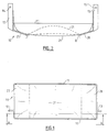
- the preferred evaporation tray 10 constructed in accordance with the present invention is shown.
- the preferred evaporation tray is constructed from two materials having differing structural properties.
- the first material is substantially rigid and provides structural support to the tray.
- the rigid material may be, for example, a tough thermosetting plastic which is used to construct a substantially rigid frame means, for example box frame 11 which, at least in the preferred form comprises a substantially rectangular box-like structure having opposed open ends and enclosed sides.
- attachment means 12 and 13 are provided on box member 11 so that the evaporation tray may be for example hung from the refrigerator cabinet 20 by the means of screws passed through holes 14 and 15.
- the second material used in the construction of the preferred evaporation tray is a more flexible material, preferably a polymeric material such as a thin plastics or rubber sheet material such as is used in plastic bag construction.
- This more flexible and deformable material is used as a flexible tray forming membrane or container membrane 21.
- the container membrane 21 comprises a rectangular sheet of plastic sheet which is attached around the perimeter of box frame 11, preferably being attached along top edge 22.
- base plates 27 and 28 are attached at a sloping angle to box frame 11 with a gap there between through which container membrane 21 may protrude.
- box frame 11 may effectively be split in two interconnecting sections, a first supporting frame means section 24 (which also provides attachment means 12 and 13) and a second interconnecting membrane support means section 25, (which has the container membrane 21 attached thereto) which when connected form join line 23.
- membrane support means section 25 is lifted away from support frame means section 24 in the direction of arrow 26.
- This alternative embodiment may be useful to allow a user to wash the container membrane 21 (should it be required) while allowing the support frame means section 24 to remain connected to the refrigeration equipment.
- the weight of defrost liquid supported by container membrane 21 helps to force the membrane against the protruding part of the compressor, regardless of the shape of the compressor. It is anticipated that the evaporation tray according to the present invention should hold a maximum of approximately 2 litres of defrost liquid. Alternatively, the evaporation tray could be positioned above part of condenser 17 with container membrane 21 in contact with at least part of the outer surface of condenser 17.
- the container membrane could be pre-formed to have a natural shape more similar to the top of the compressor housing to reduce the amount of creasing in the membrane.
- the present invention provides an improved evaporation tray which has a highly efficient and effective heat transfer mechanism.
- the present evaporation tray is also of a design which will allow it to be incorporated in refrigerators and or freezers of different sizes, unlike previous trays which were suited to a specific model only. Due to the reduction of rigid material, the production costs of the present evaporator tray are also expected to be reduced. It is possible that, due to the increase in evaporation efficiency of the tray according to the present invention, the nay may be manufactured so as to take up (and contain) a smaller volume than previous trays and accordingly, the compressor space in the rear of the refrigerator or freezer could be reduced, allowing for an increase in the volume of the cooling compartments.
Abstract
Description
- This invention relates to refrigerating and/or freezing equipment and more particularly, though not solely, to equipment used to collect and evaporate surplus (defrost) liquid water produced by refrigeration equipment.
- During the operation of refrigerating or freezing equipment (which henceforth will be generally referred to as refrigeration equipment), water (present in the form of water vapour in the air within the various compartments of the refrigeration equipment) condenses on the refrigeration equipment's cooling surfaces and is then cooled to produce ice. Eventually, the amount of ice built up on the cooling surfaces (evaporator) becomes a hindrance to the efficient operation of the cooling mechanism and may also cause structural damage due to the expansion (upon cooling) of condensed water which may have found its way into narrow gaps in the refrigeration equipment.
- In order to remove ice and liquid water from the refrigeration equipment, most refrigerators and freezers regularly, or upon instruction (for example from an operator or under software control) carry out a defrost cycle in which heat is introduced into the refrigeration equipment (from a heater element or the like) in order to melt any built up ice. The liquid thus formed (defrost liquid) may then be directed out of the various compartments of the refrigeration equipment under the influence of gravity through a system of channels and passageways. In many cases, the defrost liquid is fed to a container to be emptied by a user or alternatively, the container may be positioned adjacent to the compressor of the refrigeration equipment so that the heat produced during the normal operation of the compressor may be beneficially utilised to evaporate the defrost liquid away. In the latter embodiment, the container is called an "evaporation tray" and is usually positioned atop the compressor to take full advantage of heat conducted through the compressor housing and convected heat carried by air passing around and over the compressor.
- Conventional evaporation trays are made from a solid, inflexible plastics or metal material in the shape of a comparatively short (vertically) rectangular, open topped box. The base of the tray has, in recent times, been shaped so as to accommodate the top of the compressor in an efficient heat transfer relationship. Many compressor housings have a convex shaped top and the base of the matching evaporation trays are therefore formed with a curved section to allow the tray to contact the top of the compressor over a surface area which is as large as possible. In this way heat transfer and thus the volume of water which may be evaporated from the evaporation tray in a given time are maximised. However, the thickness of the evaporation tray reduces the amount of heat transferred from the compressor as do any air gaps formed when the evaporation tray is not in contact with the compressor housing. It has been found that the volume of water arriving at the evaporation tray varies considerably with time. During defrosting, a large volume of water arrives at the evaporation tray in a short period of time whereas during the normal operation of the refrigeration device, where the only cause of defrosting is the introduction of warm air to the compartments by the opening of a door, very little water arrives at the evaporation tray over a significantly longer period of time. In addition, when the refrigeration equipment is installed in regions of high ambient humidity, the evaporation rate from existing evaporation trays is often less than the rate of defrost liquid production. Accordingly, the evaporation tray has been required to accommodate (and attempt to evaporate as quickly as possible) a large influx of water without overflowing.
- One attempt to resolve this problem has been by the introduction of a secondary "overflow" evaporation tray which receives the overflow from the main tray atop the compressor. This setup is however undesirable as it requires extra hardware and is therefore costly. Furthermore it would be desirable to be able to produce only one model of evaporator tray in a variety of refrigeration equipment models. This is presently not possible while maintaining the required heat transfer. It would also be beneficial if the evaporation tray could be reduced in volume as this could mean a reduction in the overall volume of the refrigeration equipment set aside for the compressor could be achieved, allowing an increase in the useable cooling space within the refrigeration equipment. However, presently available evaporation trays are unable to quickly evaporate the defrost water and accordingly, must be capable of storing a large quantity of defrost water so that it may be evaporated over a comparatively longer period of time. An easily removable evaporation tray would also be desirable as it would allow the user to simply remove the tray for regular cleaning.
- It is, therefore, an object of the present invention to provide liquid collection and evaporation means for refrigeration equipment which goes some way towards overcoming the above disadvantages or which will at least provide the industry with a useful choice.
- Accordingly, in one aspect, the invention consists in liquid collection and evaporation means for refrigeration equipment adapted to collect liquid produced during the operation of said refrigeration equipment, said refrigeration equipment having a heat producing means with a heated surface characterised in that said liquid collection and evaporation means comprises
- substantially rigid frame means adapted for positioning adjacent said heated surface, and
- flexible tray forming membrane means suspended from said substantially rigid frame means which forms a tray shape capable of holding a predetermined volume of said liquid and adapted to contact and deform to the shape of said heated surface to enable heat to pass there through to evaporate said liquid.
- In a second aspect, the invention consists in refrigeration equipment having a refrigeration system which, when operational extracts heat from within said refrigeration equipment, including a heat producing means which upon energisation produces heat, said heat producing means having a surface which is heated by at least some of said heat produced by said heat producing means,
- cabinet means containing at least one cooling compartment which is cooled due to the operation of said refrigeration system, said at least one cooling compartment on occasion producing a liquid flow due to the operation of said refrigeration system,
- liquid channelling means which collect said liquid flow from within said at least one compartment and direct said liquid flow outside said at least one cooling compartment,
characterised in that - liquid collection and evaporation means are provided comprising substantially rigid frame means adapted for positioning adjacent said section of the heated surface of said heat producing means are provided and
- flexible tray forming membrane means suspended from said substantially rigid frame means which forms a tray shape capable of holding a predetermined volume of said liquid and adapted to contact and deform to the shape of said heated surface to enable heat to pass there through to evaporate said liquid.
- One preferred form of the present invention will now be described with reference to the accompanying drawings in which;
- Figure 1 is a plan elevation of an evaporation tray constructed in accordance with the preferred embodiment of the present invention,
- Figure 2 is a sectional front elevation of the evaporation tray of Figure 1 through the dash-dot line marked A-A in Figure 1,
- Figure 3 is a side elevation of the refrigeration tray of Figure 1,
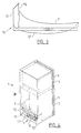
- Figure 4 is a perspective view of a refrigerator including the evaporator of Figure 1,
- Figure 5 is a perspective view of the evaporation tray of Figure 1 in use atop a refrigeration system compressor, and
- Figure 6 is a perspective view of an alternative preferred embodiment of the evaporation tray shown in Figure 5.
- With reference to the drawings and in particular Figure 4, refrigeration equipment, for example a refrigerator/
freezer 1 includes acabinet 20 enclosing at least one cooling compartment, for example aproduce compartment 2 and afreezer compartment 3. Each of the cooling compartments (2 and 3) are provided with doors (5 and 6 respectively) to allow a user to add or extract items of food or produce which are to be cooled. Arefrigeration system 7 includes acompressor 8, which is fitted externally to the cooling compartments of the refrigerator/freezer 1. Thecompressor 8 pumps refrigerant through at least one evaporator plate within the cooling compartments in the known way resulting in the cooling of the evaporator thus cooling thecompartments refrigeration system 7 also includes acondenser 17 which dissipates heat extracted from the compartments. - During the operation of the refrigeration system 7 (which is controlled by a microcontroller or microprocessor or other suitable hardware), the
compressor 8 is occasionally energised, cooling the at least one evaporator plate, reducing the temperature of the surface of and air within the compartments. As a result, water vapour from the air within the cooling compartments condenses on the cool surfaces within the compartments which, if further cooled, eventually turns to ice. In addition to the beneficial work done by the compressor in pumping refrigerant, heat is also produced which warms the outer surface of the compressor housing. Due to the operation ofcompressor 8,condenser 17, which liquefies and cools high temperature gaseous refrigerant, is also heated. - In order to remove any built up ice from within the cooling compartments, the controller occasionally runs through a defrost routine in which heat is introduced to the
compartments channels 9 within therefrigerator 1 remove the defrost liquid under the influence of gravity. The series of passageways andchannels 9 deliver the defrost liquid outside thecooling compartments example evaporation tray 10 which is constructed (as detailed below) in accordance with the preferred embodiment of the present invention. - Referring now to Figures 1, 2 and 3, the preferred
evaporation tray 10 constructed in accordance with the present invention is shown. The preferred evaporation tray is constructed from two materials having differing structural properties. The first material is substantially rigid and provides structural support to the tray. The rigid material may be, for example, a tough thermosetting plastic which is used to construct a substantially rigid frame means, forexample box frame 11 which, at least in the preferred form comprises a substantially rectangular box-like structure having opposed open ends and enclosed sides. In order to fix theevaporation tray 10 to therefrigerator 1, attachment means 12 and 13 are provided onbox member 11 so that the evaporation tray may be for example hung from therefrigerator cabinet 20 by the means of screws passed throughholes - The second material used in the construction of the preferred evaporation tray is a more flexible material, preferably a polymeric material such as a thin plastics or rubber sheet material such as is used in plastic bag construction. This more flexible and deformable material is used as a flexible tray forming membrane or
container membrane 21. In the preferred form thecontainer membrane 21 comprises a rectangular sheet of plastic sheet which is attached around the perimeter ofbox frame 11, preferably being attached alongtop edge 22. In order to assist in supportingcontainer membrane 21 and defrost liquid withincontainer membrane 21,base plates box frame 11 with a gap there between through whichcontainer membrane 21 may protrude. In an alternative embodiment shown in Figure 6,box frame 11 may effectively be split in two interconnecting sections, a first supporting frame means section 24 (which also provides attachment means 12 and 13) and a second interconnecting membrane support meanssection 25, (which has thecontainer membrane 21 attached thereto) which when connected form joinline 23. To part the two sections, membrane support meanssection 25 is lifted away from support frame meanssection 24 in the direction ofarrow 26. This alternative embodiment may be useful to allow a user to wash the container membrane 21 (should it be required) while allowing the support frame meanssection 24 to remain connected to the refrigeration equipment. - It can be seen in both of the embodiments shown in Figures 5 and 6 that the working position of the evaporation tray according to the present invention is directly over the
compressor 8 with part of the compressor protruding withinbox frame 11. In order to accommodate the part of the compressor protruding withinevaporation tray 10,container membrane 21 deforms to the shape of the protruding part ofcompressor 8. In this way, heat generated bycompressor 8 is efficiently transferred through the surface of the compressor housing protruding intotray 10, throughcontainer membrane 21 and into the defrost liquid collected in the membrane. Ascontainer membrane 21 is an easily deformed material, a large proportion of the surface area of the part ofcompressor 8 protruding into the tray will be in contact withcontainer membrane 21, providing a highly efficient heat transfer mechanism. As defrost liquid is drained to theevaporation tray 10, the weight of defrost liquid supported bycontainer membrane 21 helps to force the membrane against the protruding part of the compressor, regardless of the shape of the compressor. It is anticipated that the evaporation tray according to the present invention should hold a maximum of approximately 2 litres of defrost liquid. Alternatively, the evaporation tray could be positioned above part ofcondenser 17 withcontainer membrane 21 in contact with at least part of the outer surface ofcondenser 17. - It has been found that there is no need to specially mould the container membrane to any special profile as its easily deformable property allows a high heat transfer to occur even through overlapping or "creased" areas in the
membrane 21. However, the container membrane could be pre-formed to have a natural shape more similar to the top of the compressor housing to reduce the amount of creasing in the membrane. - Accordingly, at least in the preferred form, the present invention provides an improved evaporation tray which has a highly efficient and effective heat transfer mechanism. The present evaporation tray is also of a design which will allow it to be incorporated in refrigerators and or freezers of different sizes, unlike previous trays which were suited to a specific model only. Due to the reduction of rigid material, the production costs of the present evaporator tray are also expected to be reduced. It is possible that, due to the increase in evaporation efficiency of the tray according to the present invention, the nay may be manufactured so as to take up (and contain) a smaller volume than previous trays and accordingly, the compressor space in the rear of the refrigerator or freezer could be reduced, allowing for an increase in the volume of the cooling compartments.
- The features disclosed in the foregoing description, in the claims and/or in the accompanying drawings may, both separately and in any combination thereof, be material for realising the invention in diverse forms thereof.
Claims (20)
- Liquid collection and evaporation means (10) for refrigeration equipment (1) adapted to collect liquid produced during the operation of said refrigeration equipment (1), said refrigeration equipment (1) having a heat producing means (8, 17) with a heated surface characterised in that said liquid collection and evaporation means (10) comprisessubstantially rigid frame means (11) adapted for positioning adjacent said heated surface, andflexible tray forming membrane means (21) suspended from said substantially rigid frame means (11) which forms a tray shape capable of holding a predetermined volume of said liquid and adapted to contact and deform to the shape of said heated surface to enable heat to pass there through to evaporate said liquid.
- Liquid collection and evaporation means (10) as claimed in claim 1 wherein said substantially rigid frame means (11) is constructed from a material which is less flexible than said flexible tray forming membrane means (21).
- Liquid collection and evaporation means (10) as claimed in claim 1 or claim 2 wherein said heat producing means comprise a compressor (8) which when energised produces heat and said heated surface comprises a section of the outer surface of said compressor (8).
- Liquid collection and evaporation means (10) as claimed in claim 1 or claim 2 wherein said heat producing means comprise a condenser (17) which produces heat during operation of said refrigeration equipment (1).
- Liquid collection and evaporation means (10) as claimed in claim 1 or claim 2 wherein said flexible tray forming membrane means (21) is made from a material which may easily deform to the shape of said heated surface, substantially ensuring a maximal level of heat transfer from said heat producing means (8, 17) to said liquid within said flexible tray forming membrane means (21).
- Liquid collection and evaporation means (10) as claimed in claim 5 wherein said flexible tray forming membrane means (21) is made from a polymeric material.
- Liquid collection and evaporation means (10) as claimed in claim 5 wherein said flexible tray forming membrane means (21) is a substantially rectangular sheet of material, the area of said flexible tray forming membrane means (21) being greater than the area enclosed by said substantially rigid frame means (11).
- Liquid collection and evaporation means (10) as claimed in claim 1 or claim 2 claim wherein said substantially rigid frame means (11) comprise a substantially rectangular box-like frame having two opposing open ends.
- Liquid collection and evaporation means (10) as claimed in claim 1 or claim 2 wherein said refrigeration equipment (1) includes a cabinet means (20) and said liquid collection and evaporation means is connected to said cabinet means (20).
- Liquid collection and evaporation means (10) as claimed in claim 1 or claim 2 wherein said substantially rigid frame means (11) comprise two interconnected parts,a first supporting frame means (24) adapted for attachment to said refrigeration equipment (1) adjacent said heat producing means (8, 17), anda second interconnecting membrane supporting means (25) to which said flexible tray forming membrane (21) means is attached,
wherein when said membrane supporting means (25) is connected to said supporting frame means (24), said flexible tray forming membrane means (21) are in contact with said section of the outer surface of said heat producing means (8, 17). - Refrigeration equipment (1) having a refrigeration system (7) which, when operational extracts heat from within said refrigeration equipment (1), including a heat producing means (8, 17) which upon energisation produces heat, said heat producing means (8, 17) having a surface which is heated by at least some of said heat produced by said heat producing means (8, 17),cabinet means (20) containing at least one cooling compartment (2, 3) which is cooled due to the operation of said refrigeration system (7), said at least one cooling compartment (2, 3) on occasion producing a liquid flow due to the operation of said refrigeration system (7),liquid channelling means (9) which collect said liquid flow from within said at least one compartment (2, 3) and direct said liquid flow outside said at least one cooling compartment (2, 3),
characterised in thatliquid collection and evaporation means (10) are provided comprising substantially rigid frame means (11) adapted for positioning adjacent said section of the heated surface of said heat producing means (8, 17) are provided andflexible tray forming membrane means (21) suspended from said substantially rigid frame means (11) which forms a tray shape capable of holding a predetermined volume of said liquid and adapted to contact and deform to the shape of said heated surface to enable heat to pass there through to evaporate said liquid. - Refrigeration equipment (1) as claimed in claim 11 wherein said heat producing means comprise a compressor (8) which when energised produces heat and said heated surface comprises a section of the outer surface of said compressor (8).
- Refrigeration equipment (1) as claimed in claim 11 wherein said heat producing means comprise a condenser (17) which produces heat during operation of said refrigeration equipment (7).
- Refrigeration equipment (1) as claimed in claim 11 or claim 12 wherein said substantially rigid frame means (11) is constructed from a material which is less flexible than said flexible tray forming means (21).
- Refrigeration equipment (1) as claimed in claim 11 or claim 12 wherein said flexible tray forming membrane means (21) is made from a material which may easily deform to the shape of said heated surface, substantially ensuring a maximal level of heat transfer from said heat producing means to said liquid within said flexible tray forming membrane means (21).
- Refrigeration equipment (1) as claimed in claim 15 wherein said flexible tray forming membrane means (21) is made from a polymeric material.
- Refrigeration equipment as claimed in claim 15 wherein said flexible tray forming membrane means (21) is a substantially rectangular sheet of material, the area of said flexible tray forming membrane means (21) being greater than the area enclosed by said substantially rigid frame means (11).
- Refrigeration equipment (1) as claimed in claim11 or claim 12 wherein said substantially rigid frame means (11) comprise a substantially rectangular box-like frame having two opposing open ends.
- Refrigeration equipment (1) as claimed in claim11 or claim 12 wherein said liquid collection and evaporation means (10) is connected to said cabinet means (20).
- Refrigeration equipment (1) as claimed in claim 11 or claim 12 wherein said substantially rigid frame means (11) comprise two interconnected parts,a first supporting frame means (24) adapted for attachment to said refrigeration equipment (1) adjacent said heat producing means (8, 17), anda second interconnecting membrane supporting means (25) to which said flexible tray forming membrane means (21) is attached,
wherein when said membrane supporting means (25) is connected to said supporting frame means (24), said flexible tray forming membrane means (21) are in contact with said section of the outer surface of said heat producing means (8, 17).
Applications Claiming Priority (2)
| Application Number | Priority Date | Filing Date | Title |
|---|---|---|---|
| NZ286458A NZ286458A (en) | 1996-04-26 | 1996-04-26 | Evaporation tray to catch defrost water from refrigerator, bottom consists of flexible membrane |
| NZ28645896 | 1996-04-26 |
Publications (2)
| Publication Number | Publication Date |
|---|---|
| EP0803691A2 true EP0803691A2 (en) | 1997-10-29 |
| EP0803691A3 EP0803691A3 (en) | 1998-01-07 |
Family
ID=19925731
Family Applications (1)
| Application Number | Title | Priority Date | Filing Date |
|---|---|---|---|
| EP97106819A Withdrawn EP0803691A3 (en) | 1996-04-26 | 1997-04-24 | Evaporation device for refrigeration equipment |
Country Status (5)
| Country | Link |
|---|---|
| US (1) | US5881566A (en) |
| EP (1) | EP0803691A3 (en) |
| JP (1) | JPH1054646A (en) |
| AU (1) | AU1910497A (en) |
| NZ (1) | NZ286458A (en) |
Cited By (10)
| Publication number | Priority date | Publication date | Assignee | Title |
|---|---|---|---|---|
| WO1999060314A1 (en) * | 1998-05-19 | 1999-11-25 | Empresa Brasileira De Compressores S.A. - Embraco | An evaporation tray |
| EP1621832A1 (en) * | 2004-07-30 | 2006-02-01 | Whirpool Corporation | Domestic refrigerator |
| WO2007071718A3 (en) * | 2005-12-20 | 2007-09-07 | Acc Austria Gmbh | Coolant compressor |
| WO2009083384A2 (en) * | 2007-12-31 | 2009-07-09 | Arcelik Anonim Sirketi | A cooling device |
| CN102338531A (en) * | 2011-11-09 | 2012-02-01 | 合肥美的荣事达电冰箱有限公司 | Refrigerator |
| CN102419048A (en) * | 2011-11-09 | 2012-04-18 | 合肥美的荣事达电冰箱有限公司 | Refrigerator |
| CN103575024A (en) * | 2012-07-20 | 2014-02-12 | 合肥美的电冰箱有限公司 | Refrigerator and water tray |
| ITVI20130270A1 (en) * | 2013-11-08 | 2015-05-09 | Carel Ind Spa | REFRIGERATING MACHINE |
| EP2159520B1 (en) * | 2008-08-26 | 2018-12-12 | BSH Hausgeräte GmbH | Compressor evaporation tray assembly |
| CN109579412A (en) * | 2018-11-02 | 2019-04-05 | 海信容声(广东)冰箱有限公司 | A kind of compressor bin and refrigerator |
Families Citing this family (29)
| Publication number | Priority date | Publication date | Assignee | Title |
|---|---|---|---|---|
| US6272867B1 (en) | 1999-09-22 | 2001-08-14 | The Coca-Cola Company | Apparatus using stirling cooler system and methods of use |
| US6532749B2 (en) | 1999-09-22 | 2003-03-18 | The Coca-Cola Company | Stirling-based heating and cooling device |
| US6266963B1 (en) | 1999-10-05 | 2001-07-31 | The Coca-Cola Company | Apparatus using stirling cooler system and methods of use |
| DE19956995A1 (en) | 1999-11-26 | 2001-05-31 | Bsh Bosch Siemens Hausgeraete | Refrigerator has thermally insulated housing, door, machine volume, condensed water collection container with base and holding section connected together by variable height side wall |
| US6345514B1 (en) * | 2000-09-08 | 2002-02-12 | Lg Electronics Inc. | Device for disposing of condensate from small sized air conditioner |
| US6581389B2 (en) | 2001-03-21 | 2003-06-24 | The Coca-Cola Company | Merchandiser using slide-out stirling refrigeration deck |
| US6550255B2 (en) | 2001-03-21 | 2003-04-22 | The Coca-Cola Company | Stirling refrigeration system with a thermosiphon heat exchanger |
| DE20209839U1 (en) * | 2002-06-25 | 2002-09-12 | Bsh Bosch Siemens Hausgeraete | Compressor evaporation tray assembly |
| KR100499025B1 (en) * | 2003-03-22 | 2005-07-01 | 삼성전자주식회사 | Refrigerator |
| DE10322681A1 (en) * | 2003-05-20 | 2004-12-09 | BSH Bosch und Siemens Hausgeräte GmbH | Increase in the evaporation performance through the compressor capsule as the evaporation tray bottom |
| DE102004012498A1 (en) * | 2004-03-15 | 2005-10-06 | BSH Bosch und Siemens Hausgeräte GmbH | The refrigerator |
| DE102004035730A1 (en) * | 2004-07-23 | 2006-03-16 | BSH Bosch und Siemens Hausgeräte GmbH | Domestic refrigerating appliance with evacuable storage compartment |
| US9074812B2 (en) | 2004-12-30 | 2015-07-07 | J.F.R. Enterprises, Inc. | Drain pan with integrated riser |
| US20080202154A1 (en) * | 2005-05-10 | 2008-08-28 | Richard George Phillip Salt | Refrigeration Apparatus |
| US7278274B2 (en) * | 2005-12-27 | 2007-10-09 | Kim Brian S | Condensate evaporation device |
| DE202006005552U1 (en) * | 2006-04-05 | 2006-08-24 | BSH Bosch und Siemens Hausgeräte GmbH | Compressor arrangement for refrigerator, has evaporation trough inserted in frame, where distance of evaporation trough from compressor is greater in final position of each slide-in track than at another point on slide-in tracks |
| US9395034B1 (en) | 2006-08-04 | 2016-07-19 | J.F.R. Enterprises, Inc. | Equipment pad that includes one or more risers |
| US7891635B2 (en) * | 2006-08-04 | 2011-02-22 | J.F.R. Enterprises, Inc. | Equipment pad with integrated riser |
| BRPI0700554A (en) * | 2007-01-30 | 2008-09-16 | Whirlpool Sa | resonator arrangement for refrigeration cabinet |
| JP5713536B2 (en) * | 2009-01-05 | 2015-05-07 | 三菱電機株式会社 | Heat pump water heater |
| DE102011007414A1 (en) * | 2011-04-14 | 2012-10-18 | BSH Bosch und Siemens Hausgeräte GmbH | Evaporation device for a refrigeration device |
| CN102230710B (en) * | 2011-05-25 | 2012-11-28 | 合肥美的荣事达电冰箱有限公司 | Evaporation disk and refrigerator comprising same |
| US9080786B2 (en) | 2011-07-06 | 2015-07-14 | J.F.R. Enterprises, Inc. | Drop-front drain pan |
| US9410731B1 (en) | 2011-07-06 | 2016-08-09 | J.F.R. Enterprises, Inc. | Expandable drain pan |
| US9777945B2 (en) * | 2015-08-31 | 2017-10-03 | Chang-An Pan | Adjustable washing rack for air conditioner |
| TWI635244B (en) * | 2015-12-02 | 2018-09-11 | 國立臺灣師範大學 | Energy-saving compressor |
| CN107741117A (en) * | 2017-08-31 | 2018-02-27 | 青岛海尔股份有限公司 | Refrigerator |
| DE102018201786A1 (en) | 2018-02-06 | 2019-08-08 | BSH Hausgeräte GmbH | Refrigeration unit with evaporation tray |
| DE102019200859A1 (en) | 2019-01-24 | 2020-07-30 | BSH Hausgeräte GmbH | Refrigerator |
Family Cites Families (14)
| Publication number | Priority date | Publication date | Assignee | Title |
|---|---|---|---|---|
| US2561278A (en) * | 1948-08-02 | 1951-07-17 | Calumet And Hecla Cons Copper | Removable refrigerating apparatus |
| US2626509A (en) * | 1950-03-03 | 1953-01-27 | Willard L Morrison | High-humidity refrigerator |
| US2758449A (en) * | 1955-02-18 | 1956-08-14 | Whirlpool Seeger Corp | Horizontal blower type refrigerated cabinet |
| US2909907A (en) * | 1958-11-25 | 1959-10-27 | Whirlpool Co | Refrigerating apparatus with hot gas defrost means |
| DE1915973A1 (en) * | 1969-03-25 | 1970-10-01 | Licentia Gmbh | Two-state refrigerator automatic defrosting - dish |
| DE1919297A1 (en) * | 1969-04-16 | 1970-10-29 | Licentia Gmbh | Refrigerator defrosting tray |
| AT324370B (en) * | 1973-07-10 | 1975-08-25 | Bosch Hausgeraete Gmbh | EVUMINATION DEVICE FOR MELT WATER, IN PARTICULAR FOR PERIODICALLY DEFROSTABLE COOLING OR FREEZERS |
| GB1447538A (en) * | 1973-11-16 | 1976-08-25 | Schmitz G | Humidifier |
| US4155402A (en) * | 1977-01-03 | 1979-05-22 | Sperry Rand Corporation | Compliant mat cooling |
| US4497183A (en) * | 1984-03-23 | 1985-02-05 | General Electric Company | Compressor auxiliary condenser arrangement adapted to be mounted in a refrigerator machinery compartment |
| US4938279A (en) * | 1988-02-05 | 1990-07-03 | Hughes Aircraft Company | Flexible membrane heat sink |
| US5000256A (en) * | 1990-07-20 | 1991-03-19 | Minnesota Mining And Manufacturing Company | Heat transfer bag with thermal via |
| JPH0539977A (en) * | 1991-08-05 | 1993-02-19 | Fuji Electric Co Ltd | Drainage disposal device for refrigeration showcase |
| JPH06117747A (en) * | 1992-10-02 | 1994-04-28 | Sanyo Electric Co Ltd | Refrigerator |
-
1996
- 1996-04-26 NZ NZ286458A patent/NZ286458A/en not_active IP Right Cessation
-
1997
- 1997-04-24 AU AU19104/97A patent/AU1910497A/en not_active Abandoned
- 1997-04-24 US US08/842,416 patent/US5881566A/en not_active Expired - Fee Related
- 1997-04-24 EP EP97106819A patent/EP0803691A3/en not_active Withdrawn
- 1997-04-25 JP JP9108696A patent/JPH1054646A/en active Pending
Non-Patent Citations (1)
| Title |
|---|
| None |
Cited By (13)
| Publication number | Priority date | Publication date | Assignee | Title |
|---|---|---|---|---|
| WO1999060314A1 (en) * | 1998-05-19 | 1999-11-25 | Empresa Brasileira De Compressores S.A. - Embraco | An evaporation tray |
| EP1621832A1 (en) * | 2004-07-30 | 2006-02-01 | Whirpool Corporation | Domestic refrigerator |
| WO2007071718A3 (en) * | 2005-12-20 | 2007-09-07 | Acc Austria Gmbh | Coolant compressor |
| WO2009083384A2 (en) * | 2007-12-31 | 2009-07-09 | Arcelik Anonim Sirketi | A cooling device |
| WO2009083384A3 (en) * | 2007-12-31 | 2009-12-30 | Arcelik Anonim Sirketi | A cooling device |
| EP2159520B1 (en) * | 2008-08-26 | 2018-12-12 | BSH Hausgeräte GmbH | Compressor evaporation tray assembly |
| CN102419048A (en) * | 2011-11-09 | 2012-04-18 | 合肥美的荣事达电冰箱有限公司 | Refrigerator |
| CN102338531B (en) * | 2011-11-09 | 2014-01-15 | 合肥美的电冰箱有限公司 | Refrigerator |
| CN102338531A (en) * | 2011-11-09 | 2012-02-01 | 合肥美的荣事达电冰箱有限公司 | Refrigerator |
| CN103575024A (en) * | 2012-07-20 | 2014-02-12 | 合肥美的电冰箱有限公司 | Refrigerator and water tray |
| CN103575024B (en) * | 2012-07-20 | 2015-08-26 | 合肥美的电冰箱有限公司 | Refrigerator and drip tray |
| ITVI20130270A1 (en) * | 2013-11-08 | 2015-05-09 | Carel Ind Spa | REFRIGERATING MACHINE |
| CN109579412A (en) * | 2018-11-02 | 2019-04-05 | 海信容声(广东)冰箱有限公司 | A kind of compressor bin and refrigerator |
Also Published As
| Publication number | Publication date |
|---|---|
| EP0803691A3 (en) | 1998-01-07 |
| NZ286458A (en) | 1999-01-28 |
| JPH1054646A (en) | 1998-02-24 |
| US5881566A (en) | 1999-03-16 |
| AU1910497A (en) | 1997-10-30 |
Similar Documents
| Publication | Publication Date | Title |
|---|---|---|
| US5881566A (en) | Evaporation device for refrigeration equipment | |
| US4459826A (en) | Refrigerator | |
| US5941085A (en) | Refrigerator having an apparatus for defrosting | |
| EP3929511B1 (en) | Refrigerator | |
| US5784896A (en) | Freezer or refrigerator construction suitable for food service use | |
| US5551250A (en) | Freezer evaporator defrost system | |
| US6053003A (en) | Defrost water evaporating apparatus in a refrigerator | |
| KR20180006570A (en) | Evaporating unit and refrigerator having the same | |
| US20090013709A1 (en) | Refrigerator and evaporator for refrigerator | |
| EP0126521A2 (en) | Refrigerator | |
| KR20180011691A (en) | Evaporating unit and refrigerator having the same | |
| KR100506610B1 (en) | Refrigeration apparatus and refrigerator with the refrigeration apparatus | |
| EP0644385A1 (en) | System for reducing frost in a refrigerator | |
| JPH11264647A (en) | Deep freezer for cold-storage agent | |
| WO2006041246A1 (en) | Refrigerator | |
| KR100412416B1 (en) | installation structure of evaporator for drawer-type storage in kim-chi refrigerator | |
| KR200161840Y1 (en) | Deforsting dish for showcase | |
| KR200184620Y1 (en) | Tray-drain water for refrigerator | |
| KR0128872Y1 (en) | Refrigerator | |
| JPH0894237A (en) | High humidity low temperature storage warehouse | |
| JP6976565B2 (en) | refrigerator | |
| US2881601A (en) | Household refrigerators of the cycle defrosting type | |
| JP3133671B2 (en) | Showcase | |
| KR100557097B1 (en) | Radiating apparatus for defost water of built-in refrigerator | |
| WO2023198268A1 (en) | Refrigerator with water collector |
Legal Events
| Date | Code | Title | Description |
|---|---|---|---|
| PUAI | Public reference made under article 153(3) epc to a published international application that has entered the european phase |
Free format text: ORIGINAL CODE: 0009012 |
|
| AK | Designated contracting states |
Kind code of ref document: A2 Designated state(s): DE ES FR GB IT |
|
| PUAL | Search report despatched |
Free format text: ORIGINAL CODE: 0009013 |
|
| AK | Designated contracting states |
Kind code of ref document: A3 Designated state(s): DE ES FR GB IT |
|
| 17P | Request for examination filed |
Effective date: 19980325 |
|
| 17Q | First examination report despatched |
Effective date: 20000324 |
|
| STAA | Information on the status of an ep patent application or granted ep patent |
Free format text: STATUS: THE APPLICATION IS DEEMED TO BE WITHDRAWN |
|
| 18D | Application deemed to be withdrawn |
Effective date: 20000804 |
|
| REG | Reference to a national code |
Ref country code: HK Ref legal event code: WD Ref document number: 1000779 Country of ref document: HK |