EP0804970B1 - Hand held spray gun for high pressure cleaning apparatus - Google Patents
Hand held spray gun for high pressure cleaning apparatus Download PDFInfo
- Publication number
- EP0804970B1 EP0804970B1 EP97104296A EP97104296A EP0804970B1 EP 0804970 B1 EP0804970 B1 EP 0804970B1 EP 97104296 A EP97104296 A EP 97104296A EP 97104296 A EP97104296 A EP 97104296A EP 0804970 B1 EP0804970 B1 EP 0804970B1
- Authority
- EP
- European Patent Office
- Prior art keywords
- pipe section
- housing
- spray gun
- hand
- held spray
- Prior art date
- Legal status (The legal status is an assumption and is not a legal conclusion. Google has not performed a legal analysis and makes no representation as to the accuracy of the status listed.)
- Expired - Lifetime
Links
Images


Classifications
-
- B—PERFORMING OPERATIONS; TRANSPORTING
- B60—VEHICLES IN GENERAL
- B60S—SERVICING, CLEANING, REPAIRING, SUPPORTING, LIFTING, OR MANOEUVRING OF VEHICLES, NOT OTHERWISE PROVIDED FOR
- B60S3/00—Vehicle cleaning apparatus not integral with vehicles
- B60S3/04—Vehicle cleaning apparatus not integral with vehicles for exteriors of land vehicles
- B60S3/045—Other hand-held cleaning arrangements, e.g. with sponges, brushes, scrapers or the like
- B60S3/047—Other hand-held cleaning arrangements, e.g. with sponges, brushes, scrapers or the like using liquid or gas distributing means
-
- B—PERFORMING OPERATIONS; TRANSPORTING
- B05—SPRAYING OR ATOMISING IN GENERAL; APPLYING FLUENT MATERIALS TO SURFACES, IN GENERAL
- B05B—SPRAYING APPARATUS; ATOMISING APPARATUS; NOZZLES
- B05B12/00—Arrangements for controlling delivery; Arrangements for controlling the spray area
- B05B12/002—Manually-actuated controlling means, e.g. push buttons, levers or triggers
-
- B—PERFORMING OPERATIONS; TRANSPORTING
- B05—SPRAYING OR ATOMISING IN GENERAL; APPLYING FLUENT MATERIALS TO SURFACES, IN GENERAL
- B05B—SPRAYING APPARATUS; ATOMISING APPARATUS; NOZZLES
- B05B15/00—Details of spraying plant or spraying apparatus not otherwise provided for; Accessories
- B05B15/60—Arrangements for mounting, supporting or holding spraying apparatus
- B05B15/65—Mounting arrangements for fluid connection of the spraying apparatus or its outlets to flow conduits
- B05B15/652—Mounting arrangements for fluid connection of the spraying apparatus or its outlets to flow conduits whereby the jet can be oriented
-
- B—PERFORMING OPERATIONS; TRANSPORTING
- B05—SPRAYING OR ATOMISING IN GENERAL; APPLYING FLUENT MATERIALS TO SURFACES, IN GENERAL
- B05B—SPRAYING APPARATUS; ATOMISING APPARATUS; NOZZLES
- B05B9/00—Spraying apparatus for discharge of liquids or other fluent material, without essentially mixing with gas or vapour
- B05B9/01—Spray pistols, discharge devices
-
- B—PERFORMING OPERATIONS; TRANSPORTING
- B08—CLEANING
- B08B—CLEANING IN GENERAL; PREVENTION OF FOULING IN GENERAL
- B08B3/00—Cleaning by methods involving the use or presence of liquid or steam
- B08B3/02—Cleaning by the force of jets or sprays
- B08B3/026—Cleaning by making use of hand-held spray guns; Fluid preparations therefor
-
- B—PERFORMING OPERATIONS; TRANSPORTING
- B05—SPRAYING OR ATOMISING IN GENERAL; APPLYING FLUENT MATERIALS TO SURFACES, IN GENERAL
- B05B—SPRAYING APPARATUS; ATOMISING APPARATUS; NOZZLES
- B05B15/00—Details of spraying plant or spraying apparatus not otherwise provided for; Accessories
- B05B15/60—Arrangements for mounting, supporting or holding spraying apparatus
- B05B15/65—Mounting arrangements for fluid connection of the spraying apparatus or its outlets to flow conduits
Abstract
Description
Die Erfindung betrifft eine Handspritzpistole für ein Hochdruckreinigungsgerät mit einem Gehäuse, in das eine Flüssigkeitsleitung einmündet, die im Gehäuse um ihre Längsachse drehbar gelagert ist, wobei die Flüssigkeitsleitung ein um seine Längsachse drehbar am Gehäuse gelagertes Rohrstück umfaßt, welches an seinem freien Ende ein Verbindungsteil aufweist, mit welchem ein dazu passendes Verbindungsteil einer Schlauchleitung durch gegenseitiges Verdrehen der Schlauchleitung und des Rohrstückes lösbar verbindbar ist.The invention relates to a hand spray gun for a High-pressure cleaning device with a housing in which one Liquid line opens out in the housing around their Longitudinal axis is rotatably supported, the liquid line one rotatable about its longitudinal axis on the housing stored pipe section includes which at its free End has a connecting part with which one suitable connecting part of a hose line mutual twisting of the hose line and the Pipe piece is releasably connectable.
Derartige Handspritzpistolen dienen bei Hochdruckreinigern der Verbindung einer von einem Hochdruckreinigungsgerät kommenden Flüssigkeitsleitung, die üblicherweise in Form eines Hochdruckschlauches ausgebildet ist, und eines Abgabewerkzeuges, beispielsweise eines Strahlrohres. Außerdem befinden sich in der Handspritzpistole normalerweise Schließmittel, mit denen der Flüssigkeitsstrom unterbrochen oder in seiner Stärke geregelt werden kann.Hand spray guns of this type are used in high-pressure cleaners connecting one of a high pressure washer coming liquid line, which is usually formed in the form of a high pressure hose and a dispensing tool, for example one Beam pipe. There are also in the hand spray gun normally locking means with which the Liquid flow interrupted or in its strength can be regulated.
Für die Handhabung notwendig ist es, daß die Handspritzpistole gegenüber dem angeschlossenen Hochdruckschlauch verdrehbar ist, um auf diese Weise Verspannungen zu vermeiden.For handling it is necessary that the handgun compared to the connected high pressure hose can be twisted to tension in this way to avoid.
Es ist dazu bekannt, Hochdruckschläuche im Inneren einer
Handspritzpistole um ihre Längsachse drehbar zu lagern
(DE 34 07 744 C2). Diese bekannte Konstruktion
setzt jedoch voraus, daß zur Herstellung einer Verbindung
das Gehäuse der Handspritzpistole geöffnet wird. It is known to use high pressure hoses inside one
Hand gun to be rotated around its longitudinal axis
(
Bei einer anderen bekannten Handspritzpistole ist vorgesehen,
daß ein Hochdruckschlauch an ein in der Handspritzpistole
gelagertes Rohrstück über eine Kupplung
angeschlossen werden kann, die eine Relativverdrehung
zwischen dem Rohrstück und dem Hochdruckschlauch ermöglicht
(DE 33 00 290 A1).In another known hand-held spray gun,
that a high pressure hose to a in the handgun
stored pipe section via a coupling
can be connected, which is a relative rotation
between the pipe section and the high pressure hose
(
Bei dieser Konstruktion liegt die Drehverbindung außerhalb der Handspritzpistole und ist daher im harten Betrieb eines Hochdruckreinigungsgerätes gefährdet, in diesem Bereich können Beschädigungen auftreten.With this construction, the slewing ring is outside the hand spray gun and is therefore in tough operation a high-pressure cleaning device at risk, in Damage can occur in this area.
Aus der DE 32 36 913 A1 (vgl. Oberbegriff des Anspruchs 1) ist eine ähnliche Handspritzpistole mit verdrehbarem Druckschlauch bekannt, auch bei dieser Pistole ist es notwendig, das Gehäuse zu öffnen, um die Verbindung der drehbaren Teile der Schlauchverbindung im Inneren des Gehäuses gegenüber der Flüssigkeitsleitung zu lösen.DE 32 36 913 A1 (cf. preamble of claim 1) is a similar hand-held spray gun known with rotatable pressure hose, also at this gun it is necessary to open the case around the connection of the rotatable parts of the hose connection inside the housing opposite the liquid line to solve.
Es ist Aufgabe der Erfindung, eine Handspritzpistole der gattungsgemäßen Art so auszubilden, daß einerseits eine Drehverbindung zwischen Flüssigkeitsleitung und Handspritzpistole im Inneren der Handspritzpistole angeordnet ist und daß andererseits eine Verbindung eines Hochdruckschlauches mit der Handspritzpistole möglich wird, ohne das Gehäuse der Handspritzpistole öffnen zu müssen.It is an object of the invention to provide a hand spray gun of the generic type so that on the one hand a rotary connection between the liquid line and Hand spray gun arranged inside the hand spray gun and that on the other hand a connection of a High pressure hose possible with the hand spray gun will open without having to open the housing of the hand spray gun have to.
Diese Aufgabe wird bei einer Handspritzpistole der eingangs beschriebenen Art erfindungsgemäß dadurch gelöst, daß zwischen Gehäuse und Rohrstück wirksame Drehsicherungsmittel vorgesehen sind, die wahlweise das Rohrstück im Gehäuse gegen eine Drehung um seine Längsachse sichern oder freigeben. This task is the beginning of a hand spray gun described type solved according to the invention, that effective anti-rotation means between housing and pipe section are provided, either the pipe section in the housing against rotation about its longitudinal axis save or release.
Bei dieser Konstruktion wird eine Drehverbindung zwischen einem Rohrstück und der Handspritzpistole im Innern des Gehäuses vorgesehen, und die anzuschließende Schlauchleitung wird mit diesem Rohrstück verbunden. Diese Verbindung erfolgt dabei durch eine gegenseitige Verdrehung des Rohrstückes und der Schlauchleitung. Um diese gegenseitige Verdrehung zu ermöglichen, sind Drehsicherungsmittel vorgesehen, die das Rohrstück gegen eine Drehung im Gehäuse sichern. Das Verbindungsteil des Rohrstückes ist in diesem drehgesicherten Zustand praktisch fest mit der Handspritzpistole verbunden, so daß die Herstellung der Verbindung zur Schlauchleitung durch eine relative Drehbewegung ohne weiteres erfolgen kann. Eine ähnliche Konstruktion ist im übrigen aus der EP 0 730 911 A1 bekannt, allerdings handelt es sich dabei um eine Handbrause, wie sie im Sanitärbereich eingesetzt wird, und nicht um eine Handspritzpistole für ein Hochdruckreinigungsgerät.With this construction there is a slewing ring between a pipe section and the handgun inside of the housing and the one to be connected Hose line is connected to this pipe section. This connection is made by a mutual Twisting of the pipe section and the hose line. Around to enable this mutual twisting Anti-rotation means are provided which counter the pipe section secure a rotation in the housing. The connecting part the pipe section is in this locked state practically firmly connected to the hand spray gun, so that the connection to the Hose line without relative rotation further can be done. A similar construction is otherwise known from EP 0 730 911 A1, however it is a hand shower, as in the Plumbing is used, and not a handheld spray gun for a high pressure cleaning device.
Vorteilhaft ist es, wenn das Verbindungsteil des Rohrstückes außerhalb des Gehäuses angeordnet ist, so daß die Verbindung zwischen Schlauchleitung und Rohrstück außerhalb des Gehäuses problemlos hergestellt werden kann.It is advantageous if the connecting part of the pipe section is arranged outside the housing, so that the connection between the hose line and the pipe section can be easily produced outside the housing can.
Gemäß einer bevorzugten Ausführungsform ist das Verbindungsteil des Rohrstückes ein Gewinde, so daß die Verbindung zwischen Rohrstück und Schlauchleitung durch eine Verschraubung herstellbar ist.According to a preferred embodiment, the connecting part of the pipe section a thread, so that the connection between pipe section and hose line a screw connection can be produced.
Grundsätzlich wären aber auch andere Drehverbindungen möglich, beispielsweise eine Bajonettverbindung. In principle, however, there would also be other slewing rings possible, for example a bayonet connection.
Eine besonders günstige Ausgestaltung ergibt sich, wenn das Rohrstück als in das Gehäuse einsteckbares und in der eingesteckten Position mit einem anschließenden Leitungselement der Flüssigkeitsleitung eine abgedichtete, um die Längsachse des Rohrstückes frei drehbare Verbindung eingehendes und in axialer Richtung fixierbares Bauteil ausgebildet ist.A particularly favorable embodiment results if the pipe section as insertable into the housing and in the inserted position with a subsequent one Line element of the liquid line a sealed, freely rotatable about the longitudinal axis of the pipe section Connection incoming and fixable in the axial direction Component is formed.
Ein solches Rohrstück kann also als separates Bauteil in die Handspritzpistole eingeschoben werden und dient dann als Adapter oder Anschlußteil für eine flexible Schlauchleitung, die beispielsweise einen Schraubanschluß trägt. Auf diese Weise kann durch Verwendung unterschiedlicher Rohrstücke eine Verbindungsmöglichkeit für Schlauchleitungen mit unterschiedlichen Anschlüssen zur Verfügung gestellt werden.Such a piece of pipe can thus be a separate component are inserted into the handgun and used then as an adapter or connector for a flexible Hose line, for example a screw connection wearing. This way, by using different Pipe pieces a connection possibility for hose lines with different connections to provide.
Es ist dabei vorteilhaft, wenn die Verbindung durch das Einschieben eines Nippels in eine Hülse herstellbar ist.It is advantageous if the connection through the Push a nipple into a sleeve is.
Bei einer bevorzugten Ausführungsform kann dabei vorgesehen werden, daß die axiale Fixierung des Rohrstückes durch einen am Gehäuse verschieblichen Anschlag erfolgt, der in einer Stellung einen Vorsprung am Rohrstück hintergreift und ihn in einer anderen Stellung freigibt. Damit ist es allein durch Verschieben des Anschlages möglich, das Rohrstück vom Gehäuse zu lösen und aus diesem herauszuziehen, wenn das Einsetzen eines anderen Rohrstück erwünscht ist. In a preferred embodiment can be provided be that the axial fixation of the pipe section done by a movable stop on the housing, which in one position has a projection on the pipe section reaches behind and puts him in a different position releases. So it is only by moving the stop possible to detach the pipe section from the housing and pull out of it when inserting a other pipe section is desired.
Insbesondere kann der Anschlag ein U-förmiger Bügel sein, der quer zur Längsrichtung des Rohrstückes verschieblich am Gehäuse gelagert ist und der im eingeschobenen Zustand das Rohrstück zwischen seinen Armen aufnimmt. Der Vorsprung kann durch eine Ringschulter am Rohrstück gebildet werden, bei einer bevorzugten Ausführungsform liegt an der Ringschulter ein Wälzlager an, an dem der einschiebbare Anschlag anliegt. Dadurch wird die gegenseitige Verdrehung des Rohrstückes und des Gehäuses erleichtert.In particular, the stop can be a U-shaped bracket be displaceable transversely to the longitudinal direction of the pipe section is mounted on the housing and the inserted Condition the pipe piece between his arms receives. The lead can be gained by a ring shoulder on Pipe piece are formed in a preferred embodiment there is a rolling bearing on the shoulder of the ring against which the insertable stop rests. Thereby is the mutual rotation of the pipe section and of the housing relieved.
Eine Handspritzpistole mit einem in der beschriebenen Weise einsetzbaren Rohrstück kann auch ohne bauliche Veränderungen dazu dienen, eine flexible Schlauchleitung unmittelbar ohne Zwischenschaltung eines Rohrstükkes aufzunehmen, wenn diese Schlauchleitung an ihrem Ende entsprechende Anschlußmittel trägt, nämlich Anschlußmittel, die eine dichtende Verbindung und eine freie Verdrehbarkeit ermöglichen. Zum Beispiel könnte eine Schlauchleitung Verwendung finden, die einen Nippel trägt, der in eine Hülse des anschließenden Leitungsstückes einschiebbar ist, und die weiterhin einen Vorsprung trägt, an dem der im Gehäuse verschiebliche Anschlag anliegen kann.A handheld spray gun with one described in the Pipe piece that can be used in a manner without structural Changes serve a flexible hose line immediately without interposing a piece of pipe to record when this hose line on your End carries corresponding connection means, namely connection means, one sealing connection and one enable free rotation. For example use a hose line that has a nipple carries in a sleeve of the subsequent line piece is insertable, and still one Protrusion on which the movable in the housing Stop may be present.
Eine in dieser Weise aufgebaute Handspritzpistole dient also entweder der unmittelbaren Aufnahme einer entsprechend angepaßten flexiblen Schlauchleitung oder kann durch Einsatz eines Rohrstückes mit einem außerhalb des Gehäuses liegenden Verbindungsteil versehen werden, das an unterschiedliche Anschlüsse der verwendeten Schlauchleitungen angepaßt ist. A hand-held spray gun constructed in this way serves either corresponding to the immediate reception of one customized flexible hose line or can by using a piece of pipe with an outside of the Housing connection part are provided, the to different connections of the used Hose lines are adapted.
Die Drehsicherungsmittel, die das Rohrstück im Gehäuse gegen eine Drehung um seine Längsachse sichern, um dadurch die Herstellung der Drehverbindung zwischen Rohrstück und Schlauchleitung zu ermöglichen, kann sehr unterschiedlich ausgebildet sein. Es kann sich beispielsweise um Klemmittel handeln, die durch einen Reibschluß zwischen Rohrstück und Gehäuse die freie Verdrehbarkeit verhindern. Eine solche Verklemmung könnte beispielsweise durch verschiebbar am Gehäuse gelagerte Bremselemente erzielt werden, die an das Rohrstück andrückbar sind, oder durch ein Zusammendrücken des Gehäuses, das im zusammengedrückten Zustand reibend am Rohrstück anliegt.The anti-rotation means that the piece of pipe in the housing secure against rotation about its longitudinal axis to thereby the production of the rotary connection between the pipe section and enabling hose line can vary widely be trained. It can be, for example act clamping means by a friction free rotation between the pipe section and the housing prevent. Such a deadlock could, for example thanks to slidably mounted brake elements can be achieved, which can be pressed onto the pipe section are, or by compressing the housing, the abuts the pipe piece in the compressed state.
Gemäß einer besonders bevorzugten Ausführungsform umfassen die Drehsicherungsmittel ein verschiebbares Riegelelement, das in der gegen eine Drehung sichernden Stellung einen Formschluß zwischen Rohrstück und Gehäuse herstellt.According to a particularly preferred embodiment the anti-rotation means a sliding locking element, the one that prevents rotation Position a positive connection between the pipe section and the housing manufactures.
Günstig ist es, wenn zur Herstellung des Formschlusses im obersten Randbereich des Riegelelementes Rücksprünge gegenüber der zylindrischen Außenwand vorgesehen sind, in die Vorsprünge an der Innenwand des Gehäuses eintauchen. Es kann sich dabei insbesondere um Verstärkungsrippen an der Innenwand des Gehäuses handeln. Dieser Formschluß wird also allein durch eine entsprechende Ausgestaltung des Riegelelementes hervorgerufen, das so ausgebildet ist, daß bereits zur Verstärkung vorgesehene Rippen als Vorsprünge dienen, die in die Rücksprünge des Riegelements eingreifen und dadurch eine Verdrehung verhindern.It is favorable if to produce the positive connection Recesses in the uppermost edge area of the locking element are provided opposite the cylindrical outer wall, immerse in the protrusions on the inner wall of the housing. It can in particular be reinforcing ribs act on the inner wall of the housing. This Form closure is therefore only by a corresponding Design of the locking element caused that is formed that already intended for reinforcement Ribs serve as protrusions that go into the recesses engage the locking element and thereby a twist prevent.
Dabei kann vorgesehen sein, daß das Riegelelement am Rohrstück verschieblich gelagert ist. Das Rohrstück bildet in diesem Falle ein selbständiges Bauteil, das auch dieses Riegelelement trägt, so daß am Gehäuse selber keine besonderen baulichen Veränderungen notwendig sind.It can be provided that the locking element on Pipe piece is slidably mounted. The pipe piece in this case forms an independent component that also carries this locking element, so that on the housing itself no special structural changes necessary are.
Gemäß einer besonders bevorzugten Ausführungsform ist vorgesehen, daß das Riegelelement eine auf dem Rohrstück längsverschieblich und drehfest gelagerte Hülse ist, die in der gegen Verdrehung sichernden Stellung mit einer unrunden Außenfläche in eine komplementäre Öffnung des Gehäuses eintaucht.According to a particularly preferred embodiment provided that the locking element one on the pipe section longitudinally displaceable and rotatably mounted sleeve is in the anti-twist position with a non-circular outer surface in a complementary Immersed opening of the housing.
Dabei kann die unrunde Außenfläche und die komplementäre Öffnung des Gehäuses vorzugsweise die Form eines Mehrkantes aufweisen, insbesondere die eines Sechskantes. Diese unrunde Außenfläche, die insbesondere die Form eines Sechskantes haben kann, kann zusätzlich zu der Drehsicherung vorgesehen sein, die sich durch den Eingriff von Vorsprüngen des Gehäuses in Rücksprünge des Riegelelementes ergibt. Dadurch ergibt sich eine besonders wirksame Drehsicherung auch in dem Fall, in dem ein Gehäuse aus Kunststoff verwendet wird, das aufgrund der Eigenelastizität möglicherweise geringe Verformungen erfährt.The non-circular outer surface and the complementary Opening the housing preferably in the form of a Have polygons, especially that of a hexagon. This non-circular outer surface, which in particular the Hexagon shape can be in addition to the rotation lock can be provided, which is characterized by the Engagement of projections of the housing in recesses of the locking element results. This results in a particularly effective rotation lock also in the case in which a plastic housing is used, which due to slight deformations due to the inherent elasticity experiences.
Insgesamt ergibt sich so eine konstruktiv besonders einfache Lösung, um zum Zwecke der Verbindung des Rohrstückes und der Schlauchleitung eine Drehsicherung des Rohrstückes vorzunehmen, es genügt nämlich, die Hülse so in die Öffnung des Gehäuses einzuschieben, daß ein Formschluß hergestellt wird.Overall, this results in a special design simple solution to the purpose of connecting the pipe section and the hose line a rotation lock of the To make pipe piece, it is enough, the sleeve to insert into the opening of the housing so that a Form fit is produced.
Dabei ist weiterhin vorteilhaft, wenn die komplementäre Öffnung des Gehäuses einen Durchmesser aufweist, der das Einschieben des Rohrstückes in das Gehäuse ermöglicht. Dadurch ist sichergestellt, daß das Rohrstück ausgewechselt werden kann.It is also advantageous if the complementary Opening of the housing has a diameter that enables the insertion of the pipe section into the housing. This ensures that the pipe section can be replaced.
Bei einer speziellen Konstruktion kann vorgesehen sein, daß das Verbindungsteil am Rohrstück durch ein auf das Rohrstückende aufgeschobenes zylindrischen Anschlußstück gebildet wird, das ein Anschlußgewinde trägt und auf dem die Hülse längsverschieblich gelagert ist. Dieses Anschlußstück übernimmt also eine Doppelfunktion, einmal zur Herstellung der Verbindung mit der Schlauchleitung und zum anderen im Hinblick auf die Lagerung der verschiebbaren Hülse der Drehsicherung.In the case of a special construction, it can be provided that the connecting part on the pipe section by one on the Pipe end pushed on cylindrical connector is formed, which carries a connecting thread and on which the sleeve is mounted for longitudinal displacement. This Connector therefore takes on a double function, once to establish the connection with the hose line and secondly in terms of storage the sliding sleeve of the anti-rotation device.
Die Drehsicherung zwischen der Hülse und dem Rohrstück oder dem Anschlußstück kann durch einen unrunden Querschnitt des Rohrstückes oder des Anschlußstückes und eine komplementäre Innenfläche der Hülse erreicht werden, insbesondere kann der Querschnitt des Rohrstückes oder des Anschlußstückes die Form eines Mehrkants haben.The rotation lock between the sleeve and the pipe section or the connector can be through a non-circular cross-section the pipe section or the connection piece and a complementary inner surface of the sleeve can be achieved in particular, the cross section of the pipe section or the connection piece have the shape of a polygon.
Es ist weiterhin günstig, wenn die Hülse auf ihrer Außenseite eine Griffprofilierung aufweist, beispielsweise in Form einiger umlaufender Umfangsrippen. It is still convenient if the sleeve is on your Has a handle profile on the outside, for example in the form of several circumferential ribs.
Gemäß einer bevorzugten Ausführungsform kann das Rohrstück in einem dieses im Abstand umgebenden rohrförmigen Abschnitt des Gehäuses angeordnet sein, dieser Abschnitt mündet dann in den übrigen Teil des Gehäuses ein, in dem Schließventile und Anschlüsse für Strahlrohre etc. angeordnet sind.According to a preferred embodiment, the pipe section in a tubular surrounding this at a distance Section of the housing may be arranged, this section then flows into the remaining part of the housing a, in which closing valves and connections for jet pipes etc. are arranged.
Die nachfolgende Beschreibung bevorzugter Ausführungsformen der Erfindung dient im Zusammenhang mit der Zeichnung der näheren Erläuterung. Es zeigen:
- Figur 1:
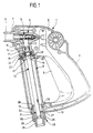
- eine Längsschnittansicht durch eine Handspritzpistole mit einem um seine Längsachse drehbaren Rohrstück;
- Figur 2:
- eine vergrößerte Längsschnittansicht im oberen und im unteren Endbereich des Rohrstückes;
- Figur 3:
- eine Schnittansicht längs Linie 3-3 in
Figur 2 und - Figur 4:
- eine Draufsicht auf ein hülsenförmiges Riegelelement.
- Figure 1:
- a longitudinal sectional view through a hand spray gun with a rotatable pipe section about its longitudinal axis;
- Figure 2:
- an enlarged longitudinal sectional view in the upper and lower end of the pipe section;
- Figure 3:
- a sectional view taken along line 3-3 in Figure 2 and
- Figure 4:
- a plan view of a sleeve-shaped locking element.
Die in der Zeichnung dargestellte Handspritzpistole 1
umfaßt ein Gehäuse aus zwei im wesentlichen spiegelsymmetrisch
ausgebildeten Halbschalen 2. Das Gehäuse nimmt
in einem oberen Teil eine zentrale Baueinheit 4 mit einem
Schließventil 5 auf, welches über einen Handgriff 6
betätigbar ist. Dieser Handgriff 6, der schwenkbar am
Gehäuse gelagert ist, verläuft längs eines Griffbereiches
3 des Gehäuses.The
An die Baueinheit 4 sind ausströmseitig Leitungsmittel
anschließbar, beispielsweise eine in der Zeichnung
nicht dargestellte Sprühlanze, dazu weist die Baueinheit
4 ein Anschlußstück 7 mit einem Außengewinde 8
auf.On the outlet side there are conduit means on the assembly 4
connectable, for example one in the drawing
Spray lance, not shown, has the unit
4 a
Im wesentlichen parallel zum Griffbereich 3 verläuft
ein im wesentlichen rohrförmiger Abschnitt 9 des Gehäuses,
der an seinem unteren Ende über einen Steg 10 mit
dem unteren Ende des Griffbereiches 3 verbunden ist. In
diesen rohrförmigen Abschnitt 9 mündet an seinem oberen
Ende die zentrale Baueinheit 4 ein mit einer sich stufenförmig
verengenden, zum Schließventil 5 führenden
Bohrung 11.Runs essentially parallel to the
Am unteren Ende steht der rohrförmige Abschnitt 9 des
Gehäuses über eine Öffnung 12 mit dem Außenraum in Verbindung,
diese Öffnung 12 wird seitlich durch parallel
zur Längsachse des rohrförmigen Abschnittes 9 verlaufende
Wände 13 begrenzt und weist den Querschnitt eines
regelmäßigen Sechsecks auf.At the lower end is the
In den rohrförmigen Abschnitt 9 ist durch die Öffnung
12 hindurch ein Rohrstück 14 eingeschoben, das an seinem
eingeschobenen Ende einen Nippel 15 trägt, der abgedichtet
in den Abschnitt 16 der Bohrung 11 mit kleinerem
Durchmesser eintaucht. In the
An den Nippel 15 schließt sich eine radial abstehende
Ringschulter 17 an, an der auf der dem Nippel gegenüberliegenden
Seite ein das Rohrstück 14 umgebendes
Wälzlager 18 anliegt. Dies kann in axialer Richtung
zwischen der Ringschulter 17 und einer weiteren Ringschulter
19 festgelegt sein. Die Ringschultern 17 und
19 und das dazwischen angeordnete Wälzlager 18 tauchen
in den Abschnitt 20 der Bohrung 11 mit größerem Durchmesser
ein.A radially protruding part is attached to the
In diesem Abschnitt 20 ist in zwei parallelen, quer zur
Längsachse der Bohrung 11 verlaufenden Bohrungen oder
Einschnitten 21 ein U-förmiger Bügel 22 verschieblich
geführt, dessen Arme 23 bei eingeschobenem Bügel 22 das
Rohrstück 14 zwischen sich aufnehmen und dadurch als
Anschlag für das Wälzlager 18 dienen. Dadurch ergibt
sich eine axiale Festlegung des Rohrstückes 14 relativ
zu der zentralen Baueinheit 4. Der Bügel 22 kann durch
eine Öffnung 24 im Gehäuse herausgezogen werden, und
dann ist es ohne weiteres möglich, das Rohrstück 14 aus
der Bohrung 11 und aus dem rohrförmigen Abschnitt 9
herauszuziehen. Die Öffnung 12 ist dabei so groß gewählt,
daß das Rohrstück 14 mit der Ringschulter 17 und
dem Wälzlager 18 durch die Öffnung 12 hindurchpaßt.This
Die beschriebene Lagerung führt zu einer lösbaren Festlegung
des Rohrstückes 14 in der zentralen Baueinheit
4, bei der eine abgedichtete Verbindung besteht, wobei
das Rohrstück 14 in axialer Richtung festgelegt ist und
um seine Längsachse frei verdrehbar bleibt. The storage described leads to a releasable determination
of the
An dem dem Nippel 15 gegenüberliegenden freien Ende des
Rohrstückes 14, das aus dem rohrförmigen Abschnitt 9
des Gehäuses hervorsteht, trägt das Rohrstück 14 ein
zylindrisches Anschlußstück 25 mit größerem Außendurchmesser,
das an seinem unteren Ende ein Außengewinde 26
aufweist, auf welches eine in der Zeichnung nicht dargestellte
flexible Schlauchleitung aufschraubbar ist.At the free end of the
An das Außengewinde 26 schließt sich zum Gehäuse hin
ein sechseckiger Mehrkantbereich 27 an, auf dem eine
Hülse 28 längsverschieblich gelagert ist. Diese Hülse
28 umgibt den Mehrkantbereich 27 dicht, so daß die Hülse
28 gegenüber dem Mehrkantbereich 27 drehfest gelagert
ist.The
Die Außenfläche der Hülse 28 ist in vier Abschnitte unterteilt,
nämlich einen gehäusefernen Griffbereich 29
mit in Umfangsrichtung umlaufenden Rippen 30, einen
daran anschließenden Mehrkantbereich 31, der komplementär
und genau passend zum Querschnitt der Öffnung 12
des Gehäuses ausgebildet ist, einen daran anschließenden,
gehäusenahen kreiszylindrischen Bereich 32, dessen
Außendurchmesser so gewählt ist, daß er beim Eintreten
in die Öffnung 12 in dieser frei verdrehbar ist, und
einen Rücksprungbereich 33, in dem gegenüber dem kreiszylindrischen
Bereich 32 radial zurückspringende Rücksprünge
34, 35 vorgesehen sind (Figur 4). Die Rücksprünge
34 sind dabei durch seitliche Abflachungen entstanden,
die Rücksprünge 35 durch einen im wesentlichen
konzentrischen Einstich mit seitlichen Begrenzungswänden
36. The outer surface of the
Die Hülse 28 kann auf dem Anschlußstück 25 zwischen einer
gehäusefernen und einer gehäusenahen Stellung verschoben
werden. In der gehäusefernen Stellung taucht
der Bereich 32 in die Öffnung 12 ein, das Rohrstück ist
dadurch im Gehäuse der Handspritzpistole 1 frei verdrehbar,
trotzdem verschließt die Hülse 28 die Öffnung
12 nach außen.The
In der gehäusenahen Stellung der Hülse 28 taucht der
Mehrkantbereich 31 in die Öffnung 12 ein und stellt dadurch
eine drehfeste Verbindung zwischen dem Gehäuse
der Handspritzpistole 1 und der Hülse 28 her. In der
gehäusenahen Stellung ist die Hülse 28 weiterhin so positioniert,
daß an der Innenwand der Halbschalen 2 angeordnete
und in den Innenraum vorstehende Verstärkungsrippen
37 in die Rücksprünge 35 eingreifen, während
Querwände 38 der Halbschalen 2 in die Rücksprünge
34 eingreifen (Figur 3). Auch dadurch ergibt sich eine
Drehsicherung zwischen Hülse 28 und Gehäuse, die zusätzlich
zu der Drehsicherung durch den Eingriff des
Mehrkantbereiches 31 in die Öffnung 12 eine sichere
Drehfixierung gewährleistet.In the position of the
Da die Hülse 28 ihrerseits auf dem Mehrkantbereich 27
des Anschlußstückes 25 drehfest gehalten ist, ergibt
sich dadurch eine Drehverriegelung des Rohrstückes 14
gegenüber dem Gehäuse der Handspritzpistole 1. In dieser
drehverriegelten Stellung der Hülse 28 kann auf das
Anschlußstück 25 eine flexible Schlauchleitung aufgeschraubt
werden, ohne daß das Außengewinde 26 des Anschlußstückes
25 irgendwie zusätzlich fixiert werden
müßte. Sobald die Verbindung hergestellt ist, kann die
Hülse 28 wieder in die gehäuseferne Stellung verschoben
werden, so daß die freie Drehbarkeit zwischen Rohrstück
14 und Handspritzpistole 1 wieder hergestellt wird.Since the
Selbstverständlich kann die Hülse 28 auch zur Drehsicherung
verwendet werden, wenn der Benutzer die Drehbarkeit
der Handspritzpistole 1 gegenüber dem Rohrstück
14 und der daran angeschlossenen Schlauchleitung aus
anderen Gründen vermeiden will, diese Hülse 28 gibt also
die Möglichkeit, wahlweise die Drehsicherung einzuschalten
oder auszuschalten.Of course, the
Claims (22)
- A hand-held spray gun (1) for a high-pressure cleaning appliance, having a housing (2) into which there opens a fluid line mounted in the housing (2) so as to be rotatable about its longitudinal axis, wherein the fluid line comprises a pipe section (14) which is mounted on the housing (2) so as to be rotatable about its longitudinal axis and the free end of which has a connecting part (25) to which a connecting part, of a hose line, adapted thereto can be detachably connected by mutual rotation of the hose line and the pipe section (14), characterised in that means (12; 28) to prevent rotation, effective between the housing (2) and the pipe section (14), are provided and in the housing (2) secure the pipe section (14) against rotation about its longitudinal axis or release it alternatively.
- A hand-held spray gun according to Claim 1, characterised in that the connecting part (25) of the pipe section (14) is arranged exterior to the housing (2).
- A hand-held spray gun according to Claim 1 or 2, characterised in that the connecting part of the pipe section (14) is a thread (26).
- A hand-held spray gun according to any one of the preceding Claims, characterised in that the pipe section (14) is in the form of a structural part which can be inserted into the housing (2) and in the inserted position enters into a sealed connection, freely rotatable about the longitudinal axis of the pipe section (14), with an adjacent line element (4) of the fluid line and which can be secured in the axial direction.
- A hand-held spray gun according to Claim 4, characterised in that the connection can be produced by pushing a fitting (15) into a sleeve (11, 16).
- A hand-held spray gun according to either one of Claims 4 or 5, characterised in that the axial securing of the pipe section (14) takes place by a stop (22, 23) which is displaceable on the housing (2) and which engages behind a projection (17, 18) on the pipe section (14) in one position and releases the projection (17, 18) in another position.
- A hand-held spray gun according to Claim 6, characterised in that the stop is a U-shaped clip (22) which is mounted on the housing (2) so as to be displaceable transversely to the longitudinal direction of the pipe section (14) and which receives the pipe section (14) between its limbs in the pushed-in state.
- A hand-held spray gun according to Claim 6 or 7, characterised in that the projection is formed by an annular shoulder (17) on the pipe section (14).
- A hand-held spray gun according to Claim 8, characterised in that a rolling bearing (18) contacts the annular shoulder (17) and the insertable stop (22, 23) rests against the rolling bearing (18).
- A hand-held spray gun according to any one of the preceding Claims, characterised in that the means to prevent rotation comprise a displaceable locking element (28) which in its position to prevent rotation produces a positive connection between the pipe section (14) and the housing (2).
- A hand-held spray gun according to Claim 10, characterised in that the locking element (28) is displaceably mounted on the pipe section (14).
- A hand-held spray gun according to Claim 11, characterised in that the locking element is a sleeve (28) which is mounted on the pipe section (14) in a longitudinally-displaceable and rotationally-fixed manner and which in the position to prevent rotation projects by means of a non-circular outer surface (31) into a complementary opening (12) in the housing (2).
- A hand-held spray gun according to Claim 12, characterised in that the non-circular outer surface (31) and the complementary opening (12) in the housing (2) have the form of a polygon.
- A hand-held spray gun according to Claim 12 or 13, characterised in that the complementary opening (12) in the housing (2) has a diameter enabling the pipe section (14) to be pushed into the housing (2).
- A hand-held spray gun according to any one of Claims 10 to 14, characterised in that in order to produce the positive connection, the uppermost peripheral region (33) of the locking element (28) is provided with offsets (34, 35) with respect to the cylindrical outer wall (32), projections (37, 38) on the inner wall of the housing (2) projecting into these offsets.
- A hand-held spray gun according to Claim 15, characterised in that the projections (37) are formed by reinforcing ribs on the inside wall of the housing (2).
- A hand-held spray gun according to any one of Claims 12 to 16, characterised in that the connecting part on the pipe section (14) is formed by a cylindrical connecting piece (25) pushed onto the end of the pipe section, which connecting piece bears a threaded connection (26) and on which the sleeve (28) is mounted in a longitudinally-displaceable manner.
- A hand-held spray gun according to any one of Claims 12 to 17, characterised in that part of the outer surface (32) of the sleeve (28) projects into the opening (12) in the housing (2) in the rotation-releasing position and is freely rotatable in the opening.
- A hand-held spray gun according to any one of Claims 12 to 18, characterised in that rotation between the sleeve (28) and the pipe section (14) or the connecting piece (25) is prevented by a non-circular cross-section of the pipe section or the connecting piece (25) and a complementary inner surface of the sleeve (28).
- A hand-held spray gun according to Claim 19, characterised in that the cross-section of the pipe section or the connecting piece (25) has the form of a polygon.
- A hand-held spray gun according to any one of Claims 12 to 20, characterised in that the sleeve (28) has grip contouring (29, 30) on its exterior.
- A hand-held spray gun according to any one of the preceding Claims, characterised in that the pipe section (14) is arranged in a tubular portion (9), of the housing (2), surrounding the pipe section (14) at a distance.
Applications Claiming Priority (2)
| Application Number | Priority Date | Filing Date | Title |
|---|---|---|---|
| DE19617417 | 1996-05-01 | ||
| DE19617417A DE19617417A1 (en) | 1996-05-01 | 1996-05-01 | Manual spray gun for a high pressure cleaning device |
Publications (3)
| Publication Number | Publication Date |
|---|---|
| EP0804970A2 EP0804970A2 (en) | 1997-11-05 |
| EP0804970A3 EP0804970A3 (en) | 1998-08-12 |
| EP0804970B1 true EP0804970B1 (en) | 2002-09-04 |
Family
ID=7792977
Family Applications (1)
| Application Number | Title | Priority Date | Filing Date |
|---|---|---|---|
| EP97104296A Expired - Lifetime EP0804970B1 (en) | 1996-05-01 | 1997-03-13 | Hand held spray gun for high pressure cleaning apparatus |
Country Status (4)
| Country | Link |
|---|---|
| EP (1) | EP0804970B1 (en) |
| AT (1) | ATE223261T1 (en) |
| DE (3) | DE19617417A1 (en) |
| DK (1) | DK0804970T3 (en) |
Cited By (1)
| Publication number | Priority date | Publication date | Assignee | Title |
|---|---|---|---|---|
| US6709440B2 (en) | 2001-05-17 | 2004-03-23 | Advanced Cardiovascular Systems, Inc. | Stent and catheter assembly and method for treating bifurcations |
Families Citing this family (3)
| Publication number | Priority date | Publication date | Assignee | Title |
|---|---|---|---|---|
| IT238406Y1 (en) * | 1997-05-22 | 2000-11-13 | Interpump Group S P A | SPRAY GUN WITH QUICK COUPLING |
| DE19743094A1 (en) * | 1997-09-30 | 1999-04-01 | Wap Reinigungssysteme | Switch-off gun for a high-pressure cleaning device with anti-twist device for the high-pressure hose |
| US20190076857A1 (en) * | 2017-09-14 | 2019-03-14 | Wagner Spray Tech Corporation | Simplified airless spray gun |
Family Cites Families (7)
| Publication number | Priority date | Publication date | Assignee | Title |
|---|---|---|---|---|
| DE2426042A1 (en) * | 1974-05-30 | 1975-12-11 | Romeico Gmbh | Vehicle wash gun spraying pipe - has movable coupling and flexible hose between lance and gun for tall vehicles |
| DE3236913A1 (en) * | 1982-10-06 | 1984-04-12 | Wolfgang 4800 Bielefeld Suttner | Spray device |
| DE3407744C2 (en) * | 1984-03-02 | 1986-01-23 | Alfred Kärcher GmbH & Co, 7057 Winnenden | Hand spray gun for a high pressure cleaning device |
| FR2658435A1 (en) * | 1990-02-19 | 1991-08-23 | Marcoulet Joseph | Multi-function shower appliance |
| DE4035008C2 (en) * | 1990-02-28 | 1993-10-28 | Suttner Gmbh & Co Kg | Hose coupling for high pressure hoses |
| JP2819005B2 (en) * | 1994-09-21 | 1998-10-30 | 株式会社喜多村合金製作所 | Shower equipment |
| DE19508638C2 (en) * | 1995-03-10 | 1997-02-27 | Hansa Metallwerke Ag | Hand shower |
-
1996
- 1996-05-01 DE DE19617417A patent/DE19617417A1/en not_active Withdrawn
- 1996-07-26 DE DE29612977U patent/DE29612977U1/en not_active Expired - Lifetime
-
1997
- 1997-03-13 AT AT97104296T patent/ATE223261T1/en not_active IP Right Cessation
- 1997-03-13 EP EP97104296A patent/EP0804970B1/en not_active Expired - Lifetime
- 1997-03-13 DK DK97104296T patent/DK0804970T3/en active
- 1997-03-13 DE DE59708099T patent/DE59708099D1/en not_active Expired - Lifetime
Cited By (1)
| Publication number | Priority date | Publication date | Assignee | Title |
|---|---|---|---|---|
| US6709440B2 (en) | 2001-05-17 | 2004-03-23 | Advanced Cardiovascular Systems, Inc. | Stent and catheter assembly and method for treating bifurcations |
Also Published As
| Publication number | Publication date |
|---|---|
| DE29612977U1 (en) | 1996-09-19 |
| DE59708099D1 (en) | 2002-10-10 |
| EP0804970A3 (en) | 1998-08-12 |
| DK0804970T3 (en) | 2002-10-07 |
| EP0804970A2 (en) | 1997-11-05 |
| DE19617417A1 (en) | 1997-11-06 |
| ATE223261T1 (en) | 2002-09-15 |
Similar Documents
| Publication | Publication Date | Title |
|---|---|---|
| DE202013103517U1 (en) | Fastening arrangement for a faucet | |
| DE19637074A1 (en) | Coupling device for connecting two pipe elements | |
| WO2000049325A1 (en) | Coupling for corrugated flexible hose | |
| DE3407744A1 (en) | HAND SPRAY GUN FOR A HIGH PRESSURE CLEANER | |
| EP2781664A1 (en) | Sanitary fitting with internal hose assembly | |
| WO2001061223A1 (en) | Rotatable stopcock for a male coupling having a 90° offset connecting piece | |
| DE4035008C2 (en) | Hose coupling for high pressure hoses | |
| DE4310192A1 (en) | Quick-fit coupling esp. for waste pipes - has insert head with flange and groove engaging in bore of socket to be locked by arms of spring clip engaging in groove. | |
| EP0804970B1 (en) | Hand held spray gun for high pressure cleaning apparatus | |
| EP1201836A2 (en) | Sanitary water tap | |
| DE4433812C2 (en) | Hose connection for connecting a hose, in particular a garden hose, to a connection nipple | |
| DE1657210B1 (en) | Filling and siphon device for tapping liquids | |
| DE19545945C1 (en) | Water tap with removable tap body | |
| DE2637143A1 (en) | HIGH PRESSURE LIQUID LINE FITTED WITH A SHUT-OFF SYSTEM | |
| WO2017042077A1 (en) | Bidet shower | |
| DE102011003864B4 (en) | Use for the water outlet from a sanitary fitting | |
| EP1561063B1 (en) | Hand-held sprayer for hose rollers | |
| DE102007058758B4 (en) | Device for draining liquid from a container | |
| DE102010012215B4 (en) | extinguisher | |
| DE8327503U1 (en) | MIXING TAP FOR WASHBASIN, BIDETS OR SEAT POOL AND THE LIKE | |
| DE202004013395U1 (en) | Water tap esp. for caravans, mobile homes, etc. has outlet tube with outlet which can be pivoted upwards to prevent residual water dripping when traveling etc. | |
| EP3935225A1 (en) | Travel shower | |
| DE8607840U1 (en) | One-hand coupling with seat valve, for hoses and / or pipes | |
| DE282092C (en) | ||
| DE7219010U (en) | Corner fitting for connecting flexible lines |
Legal Events
| Date | Code | Title | Description |
|---|---|---|---|
| PUAI | Public reference made under article 153(3) epc to a published international application that has entered the european phase |
Free format text: ORIGINAL CODE: 0009012 |
|
| AK | Designated contracting states |
Kind code of ref document: A2 Designated state(s): AT BE CH DE DK ES FI FR GB GR IE IT LI LU MC NL PT SE |
|
| PUAL | Search report despatched |
Free format text: ORIGINAL CODE: 0009013 |
|
| AK | Designated contracting states |
Kind code of ref document: A3 Designated state(s): AT BE CH DE DK ES FI FR GB GR IE IT LI LU MC NL PT SE |
|
| 17P | Request for examination filed |
Effective date: 19981008 |
|
| 17Q | First examination report despatched |
Effective date: 19990315 |
|
| GRAG | Despatch of communication of intention to grant |
Free format text: ORIGINAL CODE: EPIDOS AGRA |
|
| GRAG | Despatch of communication of intention to grant |
Free format text: ORIGINAL CODE: EPIDOS AGRA |
|
| GRAH | Despatch of communication of intention to grant a patent |
Free format text: ORIGINAL CODE: EPIDOS IGRA |
|
| GRAH | Despatch of communication of intention to grant a patent |
Free format text: ORIGINAL CODE: EPIDOS IGRA |
|
| GRAA | (expected) grant |
Free format text: ORIGINAL CODE: 0009210 |
|
| AK | Designated contracting states |
Kind code of ref document: B1 Designated state(s): AT BE CH DE DK ES FI FR GB GR IE IT LI LU MC NL PT SE |
|
| PG25 | Lapsed in a contracting state [announced via postgrant information from national office to epo] |
Ref country code: NL Free format text: LAPSE BECAUSE OF FAILURE TO SUBMIT A TRANSLATION OF THE DESCRIPTION OR TO PAY THE FEE WITHIN THE PRESCRIBED TIME-LIMIT Effective date: 20020904 Ref country code: IE Free format text: LAPSE BECAUSE OF FAILURE TO SUBMIT A TRANSLATION OF THE DESCRIPTION OR TO PAY THE FEE WITHIN THE PRESCRIBED TIME-LIMIT Effective date: 20020904 Ref country code: GR Free format text: LAPSE BECAUSE OF FAILURE TO SUBMIT A TRANSLATION OF THE DESCRIPTION OR TO PAY THE FEE WITHIN THE PRESCRIBED TIME-LIMIT Effective date: 20020904 Ref country code: FI Free format text: LAPSE BECAUSE OF FAILURE TO SUBMIT A TRANSLATION OF THE DESCRIPTION OR TO PAY THE FEE WITHIN THE PRESCRIBED TIME-LIMIT Effective date: 20020904 |
|
| REF | Corresponds to: |
Ref document number: 223261 Country of ref document: AT Date of ref document: 20020915 Kind code of ref document: T |
|
| REG | Reference to a national code |
Ref country code: GB Ref legal event code: FG4D Free format text: NOT ENGLISH |
|
| REG | Reference to a national code |
Ref country code: CH Ref legal event code: EP |
|
| REG | Reference to a national code |
Ref country code: IE Ref legal event code: FG4D Free format text: GERMAN |
|
| REG | Reference to a national code |
Ref country code: DK Ref legal event code: T3 |
|
| REF | Corresponds to: |
Ref document number: 59708099 Country of ref document: DE Date of ref document: 20021010 |
|
| PG25 | Lapsed in a contracting state [announced via postgrant information from national office to epo] |
Ref country code: SE Free format text: LAPSE BECAUSE OF FAILURE TO SUBMIT A TRANSLATION OF THE DESCRIPTION OR TO PAY THE FEE WITHIN THE PRESCRIBED TIME-LIMIT Effective date: 20021204 |
|
| PG25 | Lapsed in a contracting state [announced via postgrant information from national office to epo] |
Ref country code: PT Free format text: LAPSE BECAUSE OF FAILURE TO SUBMIT A TRANSLATION OF THE DESCRIPTION OR TO PAY THE FEE WITHIN THE PRESCRIBED TIME-LIMIT Effective date: 20021212 |
|
| NLV1 | Nl: lapsed or annulled due to failure to fulfill the requirements of art. 29p and 29m of the patents act | ||
| GBT | Gb: translation of ep patent filed (gb section 77(6)(a)/1977) |
Effective date: 20030115 |
|
| PG25 | Lapsed in a contracting state [announced via postgrant information from national office to epo] |
Ref country code: LU Free format text: LAPSE BECAUSE OF NON-PAYMENT OF DUE FEES Effective date: 20030313 Ref country code: AT Free format text: LAPSE BECAUSE OF NON-PAYMENT OF DUE FEES Effective date: 20030313 |
|
| PG25 | Lapsed in a contracting state [announced via postgrant information from national office to epo] |
Ref country code: ES Free format text: LAPSE BECAUSE OF FAILURE TO SUBMIT A TRANSLATION OF THE DESCRIPTION OR TO PAY THE FEE WITHIN THE PRESCRIBED TIME-LIMIT Effective date: 20030328 |
|
| PG25 | Lapsed in a contracting state [announced via postgrant information from national office to epo] |
Ref country code: MC Free format text: LAPSE BECAUSE OF NON-PAYMENT OF DUE FEES Effective date: 20030331 Ref country code: LI Free format text: LAPSE BECAUSE OF NON-PAYMENT OF DUE FEES Effective date: 20030331 Ref country code: CH Free format text: LAPSE BECAUSE OF NON-PAYMENT OF DUE FEES Effective date: 20030331 Ref country code: BE Free format text: LAPSE BECAUSE OF NON-PAYMENT OF DUE FEES Effective date: 20030331 |
|
| ET | Fr: translation filed | ||
| RAP2 | Party data changed (patent owner data changed or rights of a patent transferred) |
Owner name: ALFRED KAERCHER GMBH & CO. KG |
|
| REG | Reference to a national code |
Ref country code: IE Ref legal event code: FD4D Ref document number: 0804970E Country of ref document: IE |
|
| PLBE | No opposition filed within time limit |
Free format text: ORIGINAL CODE: 0009261 |
|
| STAA | Information on the status of an ep patent application or granted ep patent |
Free format text: STATUS: NO OPPOSITION FILED WITHIN TIME LIMIT |
|
| 26N | No opposition filed |
Effective date: 20030605 |
|
| BERE | Be: lapsed |
Owner name: ALFRED *KARCHER G.M.B.H. & CO. Effective date: 20030331 |
|
| REG | Reference to a national code |
Ref country code: CH Ref legal event code: PL |
|
| PGFP | Annual fee paid to national office [announced via postgrant information from national office to epo] |
Ref country code: DK Payment date: 20140311 Year of fee payment: 18 |
|
| PGFP | Annual fee paid to national office [announced via postgrant information from national office to epo] |
Ref country code: FR Payment date: 20140311 Year of fee payment: 18 Ref country code: IT Payment date: 20140310 Year of fee payment: 18 |
|
| PGFP | Annual fee paid to national office [announced via postgrant information from national office to epo] |
Ref country code: GB Payment date: 20140312 Year of fee payment: 18 |
|
| PGFP | Annual fee paid to national office [announced via postgrant information from national office to epo] |
Ref country code: DE Payment date: 20140430 Year of fee payment: 18 |
|
| REG | Reference to a national code |
Ref country code: DE Ref legal event code: R082 Ref document number: 59708099 Country of ref document: DE Representative=s name: HOEGER, STELLRECHT & PARTNER PATENTANWAELTE MB, DE |
|
| REG | Reference to a national code |
Ref country code: DE Ref legal event code: R119 Ref document number: 59708099 Country of ref document: DE |
|
| REG | Reference to a national code |
Ref country code: DK Ref legal event code: EBP Effective date: 20150331 |
|
| GBPC | Gb: european patent ceased through non-payment of renewal fee |
Effective date: 20150313 |
|
| PG25 | Lapsed in a contracting state [announced via postgrant information from national office to epo] |
Ref country code: IT Free format text: LAPSE BECAUSE OF NON-PAYMENT OF DUE FEES Effective date: 20150313 |
|
| REG | Reference to a national code |
Ref country code: FR Ref legal event code: ST Effective date: 20151130 |
|
| PG25 | Lapsed in a contracting state [announced via postgrant information from national office to epo] |
Ref country code: GB Free format text: LAPSE BECAUSE OF NON-PAYMENT OF DUE FEES Effective date: 20150313 Ref country code: DE Free format text: LAPSE BECAUSE OF NON-PAYMENT OF DUE FEES Effective date: 20151001 |
|
| PG25 | Lapsed in a contracting state [announced via postgrant information from national office to epo] |
Ref country code: FR Free format text: LAPSE BECAUSE OF NON-PAYMENT OF DUE FEES Effective date: 20150331 |
|
| PG25 | Lapsed in a contracting state [announced via postgrant information from national office to epo] |
Ref country code: DK Free format text: LAPSE BECAUSE OF NON-PAYMENT OF DUE FEES Effective date: 20150331 |