EP0804977B1 - Automotive sunshade panel and method of manufacturing same - Google Patents
Automotive sunshade panel and method of manufacturing same Download PDFInfo
- Publication number
- EP0804977B1 EP0804977B1 EP97302392A EP97302392A EP0804977B1 EP 0804977 B1 EP0804977 B1 EP 0804977B1 EP 97302392 A EP97302392 A EP 97302392A EP 97302392 A EP97302392 A EP 97302392A EP 0804977 B1 EP0804977 B1 EP 0804977B1
- Authority
- EP
- European Patent Office
- Prior art keywords
- roll
- panel
- hollow
- bending
- hollow panel
- Prior art date
- Legal status (The legal status is an assumption and is not a legal conclusion. Google has not performed a legal analysis and makes no representation as to the accuracy of the status listed.)
- Expired - Lifetime
Links
Images

Classifications
-
- B—PERFORMING OPERATIONS; TRANSPORTING
- B21—MECHANICAL METAL-WORKING WITHOUT ESSENTIALLY REMOVING MATERIAL; PUNCHING METAL
- B21D—WORKING OR PROCESSING OF SHEET METAL OR METAL TUBES, RODS OR PROFILES WITHOUT ESSENTIALLY REMOVING MATERIAL; PUNCHING METAL
- B21D5/00—Bending sheet metal along straight lines, e.g. to form simple curves
- B21D5/14—Bending sheet metal along straight lines, e.g. to form simple curves by passing between rollers
- B21D5/146—Bending sheet metal along straight lines, e.g. to form simple curves by passing between rollers one roll being covered with deformable material
-
- B—PERFORMING OPERATIONS; TRANSPORTING
- B21—MECHANICAL METAL-WORKING WITHOUT ESSENTIALLY REMOVING MATERIAL; PUNCHING METAL
- B21D—WORKING OR PROCESSING OF SHEET METAL OR METAL TUBES, RODS OR PROFILES WITHOUT ESSENTIALLY REMOVING MATERIAL; PUNCHING METAL
- B21D5/00—Bending sheet metal along straight lines, e.g. to form simple curves
- B21D5/06—Bending sheet metal along straight lines, e.g. to form simple curves by drawing procedure making use of dies or forming-rollers, e.g. making profiles
- B21D5/08—Bending sheet metal along straight lines, e.g. to form simple curves by drawing procedure making use of dies or forming-rollers, e.g. making profiles making use of forming-rollers
-
- B—PERFORMING OPERATIONS; TRANSPORTING
- B21—MECHANICAL METAL-WORKING WITHOUT ESSENTIALLY REMOVING MATERIAL; PUNCHING METAL
- B21D—WORKING OR PROCESSING OF SHEET METAL OR METAL TUBES, RODS OR PROFILES WITHOUT ESSENTIALLY REMOVING MATERIAL; PUNCHING METAL
- B21D5/00—Bending sheet metal along straight lines, e.g. to form simple curves
- B21D5/06—Bending sheet metal along straight lines, e.g. to form simple curves by drawing procedure making use of dies or forming-rollers, e.g. making profiles
- B21D5/10—Bending sheet metal along straight lines, e.g. to form simple curves by drawing procedure making use of dies or forming-rollers, e.g. making profiles for making tubes
- B21D5/12—Bending sheet metal along straight lines, e.g. to form simple curves by drawing procedure making use of dies or forming-rollers, e.g. making profiles for making tubes making use of forming-rollers
-
- Y—GENERAL TAGGING OF NEW TECHNOLOGICAL DEVELOPMENTS; GENERAL TAGGING OF CROSS-SECTIONAL TECHNOLOGIES SPANNING OVER SEVERAL SECTIONS OF THE IPC; TECHNICAL SUBJECTS COVERED BY FORMER USPC CROSS-REFERENCE ART COLLECTIONS [XRACs] AND DIGESTS
- Y10—TECHNICAL SUBJECTS COVERED BY FORMER USPC
- Y10T—TECHNICAL SUBJECTS COVERED BY FORMER US CLASSIFICATION
- Y10T156/00—Adhesive bonding and miscellaneous chemical manufacture
- Y10T156/10—Methods of surface bonding and/or assembly therefor
- Y10T156/1002—Methods of surface bonding and/or assembly therefor with permanent bending or reshaping or surface deformation of self sustaining lamina
- Y10T156/1007—Running or continuous length work
- Y10T156/1008—Longitudinal bending
- Y10T156/101—Prior to or during assembly with additional lamina
Definitions
- the present invention relates to an automotive sunshade panel formed from a hollow panel having a two-dimensional or three-dimensional curved surface conforming to a bent curved surface in the form of the top of an automobile, and to a method of manufacturing such an automotive sunshade panel.
- JP-A-08-090080 discloses a method of manufacturing through bulging a bent panel having inflations serving as reinforcing ribs from an aluminum Roll-Bond panel stock.
- a forming machine provided with a forming surface having a curved surface of a radius of curvature to be formed.
- a planar stock is disposed on the forming machine.
- a punch holder of the forming machine is then lowered to chuck the peripheries of the planar stock. With the peripheries being chucked, the planar stock is finally brought into abutment against the forming surface.
- a multiplicity of dies corresponding to various types of vehicles are required, and hence relatively small-lot products result uneconomically in a relative increase of cost used up by the dies.
- the invention described in the above publication uses an aluminum Roll-Bond panel as stock.
- This stock tends to bring about a decrease in the gauge direction with a forming force during the press forming, as well as deficiencies such as collapse of the inflated portions.
- fabrics are typically laminated to the automotive sunshade panel, they must be laminated to the curved surface after pressing since lamination before pressing may possibly allow the fabrics to peel off under the action of lubricant used in the pressing process. This resulted in increased number of working steps and was costly.
- Typical stock for the automotive sunshade panel can be a thermoset resin sheet, a steel sheet, or an aluminum sheet, with a recent attention paid to the aluminum sheet (including aluminum alloy sheet) in terms of its lightweight and recyclability.
- the aluminium sheet has a gauge of the order of 0.8 to 1.0 mmt for pressing process.
- twin rolls consisting of a metal roll 1 and a resin roll 2 as shown in Fig. 2.
- a method of manufacturing an automotive sunshade panel comprises bending a hollow panel having longitudinal edges by means of twin rolls consisting of a rigid roll and an elastic roll, in the roll circumferential direction (Y-Y axis), and flanging said longitudinal edges of said hollow panel by press forming or roll forming.
- a method of manufacturing an automotive sunshade panel comprises flanging longitudinal edges of a hollow panel by press forming or roll forming, and bending said hollow panel by means of twin rolls consisting of a rigid roll and an elastic roll, in the roll circumferential direction (Y-Y axis).
- the present invention provides a method of manufacturing an automotive sunshade panel which overcomes the above problems involved in the prior art techniques.
- the present invention also enables an automotive sunshade panel to be made by use of means capable of coping with a wide variety of types of vehicles through a simple method without additional processes such as bulging with expensive dies, as well as means extremely effective for the manufacture of products in relatively small lots.
- the present inventors have researched in depth the use of twin rolls consisting of a rigid roll and an elastic roll as shown in Fig. 2 to form aluminum panel stocks having large radii of curvature such as automobile sunshade panels.
- Fig. 2 aluminum panel stocks having large radii of curvature
- the present invention was conceived based on such a knowledge.
- an automotive sunshade panel having longitudinal flanged edges and having a two-dimensional or three-dimensional curved surface formed at least partially of the central part excepting the peripheries of the metallic hollow panel.
- a fabric may be laminated to at least one side of the hollow panel.
- the metallic hollow panel can be formed into a one-side inflated Roll-Bond panel, a two-side inflated Roll-Bond panel, a both-side flat three-layer Roll-Bond panel or a honeycomb panel.
- the metallic hollow panel is first bent in the roll circumferential direction (Y-Y axis) by means of twin rolls consisting of a rigid roll and an elastic roll, and then is subjected to a flanging process in which its longitudinal edges are flanged by press forming or roll forming.
- the metallic hollow panel may be first subjected to the flanging process in which its longitudinal edges are flanged by press forming or roll forming, and then be bent in the roll circumferential direction (Y-Y axis) by means of the twin rolls consisting of the rigid roll and the elastic roll.
- the above hollow panel may carry fabrics laminated to at least one side thereof.
- the hollow panel can be a one-side inflated Roll-Bond panel, a both-side inflated Roll-Bond panel, a both-side flat three-layer Roll Bond panel or a honeycomb panel.
- the twin rolls Upon the execution of bending process in the roll circumferential direction (Y-Y axis) by means of the twin rolls consisting of the rigid roll and the elastic roll, there may be used as the twin rolls so-called crown rolls, that is, cambered rolls having curvatures in the roll axial direction, so as to achieve bending in the roll axial direction (X-X axis) in addition to the bending in the roll circumferential direction (Y-Y axis) to consequently effect three-dimensional bending.
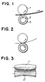
- Fig. 1 is an explanatory view showing an example of a method of forming a hollow panel curved surface in accordance with the present invention.
- reference numeral 1 denotes a metal roll serving as a rigid roll
- reference numeral 2 denotes a resin roll serving as an elastic roll.
- the surface of the resin roll 2 is coated with an elastic material, typically an urethane rubber layer 3.
- the metal roll 1 is first lowered to press against the urethane rubber roll surface 3.
- a hollow panel is then passed through the nip between the two rolls under such a condition, it is bent in the roll circumferential direction (Y-Y axis) at a radius of curvature along a depression area R formed in the urethane having an elasticity.
- the hardness of the urethane resin can be 50 to 90 degrees, preferably 55 to 65 degrees.
- the roll gap and compression ratio may be varied to achieve a desired radius of curvature. It is to be appreciated that there can also be obtained a continuously curved surface or a trapezoidal surface through two point bending due to partial release of the compressive force.
- the radius of curvature is typically of the order of 1000 to 15000 mm, whereas for the trapezoidal bending, the radius of curvature is typically of the order of 150 to 300 mm.
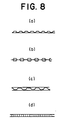
- a hollow panel to be formed Used as a hollow panel to be formed is a panel having hollow portions within its interior and consisting of two or three sheet stocks as shown in Fig. 8(a) to Fig. 8(d).
- a one-side inflated Roll-Bond panel shown in Fig. 8(a) is formed as follows. Two aluminum sheets are prepared at first for the process in which they are subjected to the steps of: chemically removing a harmful fat or stain from their surfaces; and mechanically removing therefrom an oxide layer by using a wire brush so that their fresh surfaces are exposed to the following treatments.
- a bond inhibitor which is applied to such a fresh surface of at least one aluminum plate, covers its areas in a predetermined pattern where the reinforcing ribs are to be formed.
- An ink composed mainly of colloidal graphite having a particle diameter of 1 um or less is used in general as the bond inhibitor, and is usually applied to said surface by the printing technique.
- the two aluminum sheets are overlaid upon one another such that the surface carrying the bond inhibitor is closed. Subsequently, they are hot rolled by rolls and under a condition which can ensure a sufficient strength of the bonded plates.
- the sheets are tightly consolidated and from a single panel, with areas printed with the inhibitor however remaining unbonded.
- a compressed fluid such as compressed air is forced from a side edge into the clearances, which are present between the plates on their areas where the bond inhibitor exists.
- the areas of the predetermined pattern are inflated in this manner so that the thus expanded hollow portions protrude inwards in a roll bonded panel.
- This panel has thus no lugs or protrusions on its outer surface, but has only on its inner surface the reinforcing ribs of a desired height and cross-sectional shape. This process may therefore be called "one-side inflation" process.
- an outer aluminum plate which is made of a heat-treatable aluminum alloy.
- a double-side flat three-layer Roll-Bond panel as shown in Fig. 8(c) is formed by providing alternate patterns on both sides of the intermediate of three sheet stocks so as to obtain planar exterior surfaces.
- a honeycomb panel as shown in Fig. 8(d) includes a plurality of sheet stocks arranged in a so-called honeycomb form between top and bottom sheet stocks. The channel patterns of such hollow panels are not intended to be limited to any specific ones.
- the hollow panel In the case of using as the hollow panel the one-side inflated Roll-Bond panel shown in Fig. 8(a), it is preferable that it be passed through the nip between the two rolls so that its flat side comes into contact with the rigid (metal) roll 1 with its inflated side coming into contact with the elastic (resin) roll 2.
- the hollow panel is the double-side inflated Roll-Bond panel as shown in Fig. 8(b) or the double-side flat three-layer Roll-Bond panel as shown in Fig. 8(c) or the panel as shown in Fig. 8(d)
- either side of the hollow panel may abut against the rigid (metal) roll 1 .
- the hollow panel of the present invention can be used as the metallic material for the hollow panel of the present invention.
- the hollow panel should be annealed or partially-annealed.
- the present invention will hereinafter be described for the aluminum hollow panel, but it is natural that the same apply to the copper panel. Additionally, the original sheet stocks for the hollow panel of the present invention may be multi-cavity molded.
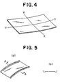
- Fig. 3 illustrates cambered rolls 1" and 2" whose roll forming surfaces have curvatures, for use as the twin rolls comprising metal/resin rolls serving as rigid/elastic rolls.
- Use of such cambered rolls provides a sunshade panel having a radius of curvature in the roll axial direction (X-X axis), thereby achieving three-dimensional bending as shown in Fig. 4 in cooperation with the bending in the roll circumferential direction (Y-Y axis).
- the forming surface of the rigid (metal) roll 1" may be convex with the elastic (resin) roller 2" having a concave surface, or vice versa.
- the rigid (metal) roll 1' has a convex surface.
- a curvature R of bending in the roll axial direction (X-X axis) is typically 2000 mm or more.
- the size of the hollow panel is about 300 to 1000 mm in width and about 600 to 1000 mm in length.
- the hollow panel is subjected to a flanging process which includes bending both edges of the hollow panel into concave or U-shaped sections as shown in Figs. 5a and 5b by means of press working or roll forming.
- a flanging process will ensure a formation of the hollow panel presenting embossing effect.
- the flanging process not only has an effect of enhancing the plate rigidity, but also is indispensable as safety measures in order to prevent plate cut surfaces from injuring a driver or fellow passengers.
- Fig. 6 illustrates another example of the method in accordance with the present invention.
- a hollow panel first undergoes a flanging process in which its longitudinal edges are bent into concave or U-shaped sections by means of press working or roll forming (Figs. 6(a) and 6(b)).
- Use is then made of twin rolls as shown in Fig. 6(c) consisting of a rigid roll 1' made of metal, wood, or the like having a width slightly smaller than that of the planar central portion of the flanged hollow panel, and an elastic roll 2' having a surface coated with urethane or the like and a width larger than that of the rigid roll 1'.
- This method also ensures the acquisition of substantially the same formed article as that shown in Fig. 5.
- the die production cost in the Fig. 6 forming method is further reduced as compared with the Fig. 5 method.
- a panel centrally having a three-dimensional curved surface can be obtained if cambered rolls 1" and 2" having roll forming surfaces with curvatures are used as the twin rolls comprising rigid/elastic rolls.
- the present invention employs the metal roll and resin roll as the rigid roll and elastic roll, respectively, the combination of the rigid/elastic rolls is not intended to be limited to the combination of the metal/resin rolls and any combination is available as long as the roll surfaces have rigidity/elasticity.
- the present invention will thus provide automotive sunshade panels each having longitudinal edges of concave or U shape in section and having an embossed central portion in the form of a continuous curved surface, a trapezoidal curved surface or a three-dimensional curved surface.
- Those automotive sunshade panels may be manufactured by either of the two methods set forth hereinabove.
- a fabric Prior to the rolling process, a fabric may be laminated onto the hollow panel. Due to a relatively small pressure used for the forming process in the method of the present invention, the fabric will not be damaged in spite of pre-forming lamination of the fabric onto the hollow panel. An increase in production costs is thus prevented which may arise from skillful work necessary for post-forming fabric lamination on curved surfaces as in the prior art.
- Test Specimen A one-side inflated Roll-Bond panel; pre-inflation gauge 1.2 (0.6 x 2) A1100-O Test Specimen B: double-side inflated Roll-Bond panel; pre-inflation gauge 1.2 (0.6 x 2) A1100-O Test Specimen C: double-side flat Roll-Bond panel; pre-inflation gauge 1.2 (0.4 x 3) A1100-O Test Specimen D: double-side flat honeycomb panel; overall gauge 3.8 (0.4 + 3 + 0.4) A1100-H24
- test specimens were each dimensioned to be 400 x 750 mm and the test specimens having fabric laminated surfaces were also tested.
- a rubber-based spray-type adhesive for fabric lamination, a thick close-woven wool fabric of 1 mmt in thickness is laminated on the flat surface, with a non-woven fabric of 0.2 mmt in thickness laminated on the patterned surface.
- Used as the upper roll and the lower roll were a metal roll (roll diameter: 65 mm) and an urethane resin roll (roll diameter: 160 mm; hardness: 60 degrees), respectively.
- a metal roll roll
- an urethane resin roll roll diameter: 160 mm; hardness: 60 degrees
- Table 1 shows results of the pre/post-bending sheet gauge and bending curvature for each of the specimens.
- test specimens A to D tested in the Embodiment 1 were first subjected to the pressing process to bend the hollow panel edges into U-shaped sections. They were then subjected to the two-dimensional bending process by means of the twin rolls shown in Fig. 6(c). The execution of these steps resulted in a two-dimensionally bent automotive sunshade panel having substantially the same flanging form as shown in Figs. 7a and 7b.
- test specimens A to D tested in the Embodiment 1 were subjected to three-dimensional bending process in the same manner except for the use of the cambered rolls as the upper and lower rolls.
- the upper metal roll 1" had a convex crown of 10,000 mm in radius of curvature
- the lower urethane resin roll 2" had a concave crown of 10,000 mm in radius of curvature.
- Table 2 After the execution of the three-dimensional bending process, the hollow panels were subjected to the flanging process.
- Test specimen D includes a 0.4 mm skin and a 0.2 mm cell.
- Table 1 revealed that adjustment of the roll gap enabled curved surfaces having arbitrary radii of curvature to be obtained in the two-dimensional bending.
- the tolerances may be influenced by variability in overall thickness of the Roll-Bond inflation, it is envisaged that there is no problem as long as the inflation thickness tolerances lie within the range of ⁇ 0.1 mm.
- Table 2 has proved that the R dimensions of the three-layered Roll-Bond panels lie within permissible tolerances in terms of design R dimensions of products although the three-dimensional bending presents a somewhat larger radius of curvature than the R of the roll crown due to differences in structural rigidity of the stocks.
- the Y-Y axis R may become large to some extent if conformed to 2,500 mm of X-X axis R, which would however be within the design permissible tolerances. The above test results have thus ensured that the resultant hollow panels entail no problems in terms of form and are conveniently suitable as automotive sunshade panels.
- automotive sunshade panels which meet requirements therefor, having a two-dimensional curved surface of 5000 mm in Y-Y axis R or having a three-dimensional curved surface of 5000 mm in Y-Y axis R and of 2000 mm in X-X axis R, at reduced production costs due to no need for any specific dies and without requiring conventional reinforcing ribs for stabilizing the curved surfaces due to substantially no occurrence of spring back.
Description
- The present invention relates to an automotive sunshade panel formed from a hollow panel having a two-dimensional or three-dimensional curved surface conforming to a bent curved surface in the form of the top of an automobile, and to a method of manufacturing such an automotive sunshade panel.
- To manufacture a bent panel having a large radius of curvature such as an interior side sunshade panel for an automotive sunroof, in the prior art techniques, the pressed body obtained from press work using dies and reinforcing members such as ribs were assembled together by bonding means including spot welding, riveting, adhesion, etc, since typical roll-based bending work often gave birth to spring back resulting in a dimensional instability. JP-A-08-090080 discloses a method of manufacturing through bulging a bent panel having inflations serving as reinforcing ribs from an aluminum Roll-Bond panel stock. For the manufacture of the bent panel, in the above invention, use was made of a forming machine provided with a forming surface having a curved surface of a radius of curvature to be formed. A planar stock is disposed on the forming machine. A punch holder of the forming machine is then lowered to chuck the peripheries of the planar stock. With the peripheries being chucked, the planar stock is finally brought into abutment against the forming surface. In the case of press forming an automotive sunshade panel by means of dies as in those conventional methods, however, a multiplicity of dies corresponding to various types of vehicles are required, and hence relatively small-lot products result uneconomically in a relative increase of cost used up by the dies.
Furthermore, the invention described in the above publication uses an aluminum Roll-Bond panel as stock. This stock tends to bring about a decrease in the gauge direction with a forming force during the press forming, as well as deficiencies such as collapse of the inflated portions. Although fabrics are typically laminated to the automotive sunshade panel, they must be laminated to the curved surface after pressing since lamination before pressing may possibly allow the fabrics to peel off under the action of lubricant used in the pressing process. This resulted in increased number of working steps and was costly. - Typical stock for the automotive sunshade panel can be a thermoset resin sheet, a steel sheet, or an aluminum sheet, with a recent attention paid to the aluminum sheet (including aluminum alloy sheet) in terms of its lightweight and recyclability. In view of rigidity and cost-saving, the aluminium sheet has a gauge of the order of 0.8 to 1.0 mmt for pressing process. On the contrary, it has been hitherto known to bend the stock by use of twin rolls consisting of a metal roll 1 and a
resin roll 2 as shown in Fig. 2. In the case of bending the aluminium sheet of the order of 0.8 to 1.0 mmt in gauge by using the above metal/resin roll pairs serving as rigid/elastic roll pairs, it would be possible to perform bending with a relatively small radius of curvature, but impossible to bend the stock having a relatively large radius of curvature of the order of 2500 to 10000 mm due to the influence of the spring back. Thus, the reinforcing members such as ribs become indispensable and the configuration is unstable, leaving unsolved the problems including dependence on the press forming and fabric lamination after press forming. - In accordance with a first aspect of the present invention, a method of manufacturing an automotive sunshade panel comprises bending a hollow panel having longitudinal edges by means of twin rolls consisting of a rigid roll and an elastic roll, in the roll circumferential direction (Y-Y axis), and flanging said longitudinal edges of said hollow panel by press forming or roll forming.
- In accordance with a second aspect of the present invention, a method of manufacturing an automotive sunshade panel comprises flanging longitudinal edges of a hollow panel by press forming or roll forming, and bending said hollow panel by means of twin rolls consisting of a rigid roll and an elastic roll, in the roll circumferential direction (Y-Y axis).
- The present invention provides a method of manufacturing an automotive sunshade panel which overcomes the above problems involved in the prior art techniques.
- The present invention also enables an automotive sunshade panel to be made by use of means capable of coping with a wide variety of types of vehicles through a simple method without additional processes such as bulging with expensive dies, as well as means extremely effective for the manufacture of products in relatively small lots.
- The present inventors have researched in depth the use of twin rolls consisting of a rigid roll and an elastic roll as shown in Fig. 2 to form aluminum panel stocks having large radii of curvature such as automobile sunshade panels. As a result of this, we reached a knowledge that use of hollow panels as the aluminum stocks would enable two-dimensional or thee-dimensional bending process to be relatively easily performed by means of the twin rolls consisting of the rigid roll and elastic roll, without giving rise to any reduction in the panel gauge direction which may often occur in the press forming process. The present invention was conceived based on such a knowledge.
- Thus, according to the present invention, there is provided an automotive sunshade panel having longitudinal flanged edges and having a two-dimensional or three-dimensional curved surface formed at least partially of the central part excepting the peripheries of the metallic hollow panel. For use in the present invention, a fabric may be laminated to at least one side of the hollow panel. The metallic hollow panel can be formed into a one-side inflated Roll-Bond panel, a two-side inflated Roll-Bond panel, a both-side flat three-layer Roll-Bond panel or a honeycomb panel.
- In order to obtain such an automotive sunshade panel of the present invention, the metallic hollow panel is first bent in the roll circumferential direction (Y-Y axis) by means of twin rolls consisting of a rigid roll and an elastic roll, and then is subjected to a flanging process in which its longitudinal edges are flanged by press forming or roll forming. Alternatively, the metallic hollow panel may be first subjected to the flanging process in which its longitudinal edges are flanged by press forming or roll forming, and then be bent in the roll circumferential direction (Y-Y axis) by means of the twin rolls consisting of the rigid roll and the elastic roll. For this manufacture, the above hollow panel may carry fabrics laminated to at least one side thereof. The hollow panel can be a one-side inflated Roll-Bond panel, a both-side inflated Roll-Bond panel, a both-side flat three-layer Roll Bond panel or a honeycomb panel. Upon the execution of bending process in the roll circumferential direction (Y-Y axis) by means of the twin rolls consisting of the rigid roll and the elastic roll, there may be used as the twin rolls so-called crown rolls, that is, cambered rolls having curvatures in the roll axial direction, so as to achieve bending in the roll axial direction (X-X axis) in addition to the bending in the roll circumferential direction (Y-Y axis) to consequently effect three-dimensional bending.
- Some examples of methods according to the present invention will now be described with reference to the accompanying drawings, in which:-
- Fig. 1 is an explanatory diagram of a bending process in accordance with the present invention, depicting sheet stock bending process by means of twin rolls consisting of a rigid roll and an elastic roll;
- Fig. 2 is an explanatory diagram of a principle of the sheet stock bending process by means of the twin roll consisting of the rigid roll and the elastic roll;
- Fig. 3 is an explanatory diagram of the sheet stock bending process by means of a cambered twin rolls consisting of a rigid roll and an elastic roll;
- Fig. 4 is a schematic explanatory diagram of a three-dimensionally bent sheet stock;
- Figs. 5(a) and 5(b) are explanatory diagrams in perspective view and in sectional view taken along a line A-A of Fig. 5(a), respectively, showing a flanging process in accordance with the present invention and a resultant hollow panel;
- Figs. 6(a), 6(b) and 6(c) are explanatory diagrams showing another process of the method of the present invention, Fig. 6(a) depicting a flanged hollow panel, Fig 6(b) being a sectional view of Fig. 5(a) taken along a line A-A, and Fig. 6(c) depicting the flanged hollow panel being subjected to a process of bending in the roll circumferential direction (Y-Y axis) by means of the twin rolls;
- Fig. 7 illustrates a two-dimensionally bent automotive sunshade panel of the present invention obtained by the process shown in Fig. 6; and
- Fig. 8(a) to 8(d) are explanatory diagrams in section of hollow panels for use in the present invention, depicting respectively a one-side inflated Roll-Bond panel, a both-side inflated Roll-Bond panel, a both-side flat three-layered Roll-Bond panel and a honeycomb panel.
-
- Fig. 1 is an explanatory view showing an example of a method of forming a hollow panel curved surface in accordance with the present invention. In Fig. 1, reference numeral 1 denotes a metal roll serving as a rigid roll, and
reference numeral 2 denotes a resin roll serving as an elastic roll. The surface of theresin roll 2 is coated with an elastic material, typically an urethane rubber layer 3. The metal roll 1 is first lowered to press against the urethane rubber roll surface 3. When a hollow panel is then passed through the nip between the two rolls under such a condition, it is bent in the roll circumferential direction (Y-Y axis) at a radius of curvature along a depression area R formed in the urethane having an elasticity.
In this case, the hardness of the urethane resin can be 50 to 90 degrees, preferably 55 to 65 degrees. The roll gap and compression ratio may be varied to achieve a desired radius of curvature. It is to be appreciated that there can also be obtained a continuously curved surface or a trapezoidal surface through two point bending due to partial release of the compressive force. For the bending in the roll circumferential direction (Y-Y axis), the radius of curvature is typically of the order of 1000 to 15000 mm, whereas for the trapezoidal bending, the radius of curvature is typically of the order of 150 to 300 mm. - Used as a hollow panel to be formed is a panel having hollow portions within its interior and consisting of two or three sheet stocks as shown in Fig. 8(a) to Fig. 8(d).
- A one-side inflated Roll-Bond panel shown in Fig. 8(a) is formed as follows. Two aluminum sheets are prepared at first for the process in which they are subjected to the steps of: chemically removing a harmful fat or stain from their surfaces; and mechanically removing therefrom an oxide layer by using a wire brush so that their fresh surfaces are exposed to the following treatments. A bond inhibitor, which is applied to such a fresh surface of at least one aluminum plate, covers its areas in a predetermined pattern where the reinforcing ribs are to be formed. An ink composed mainly of colloidal graphite having a particle diameter of 1 um or less is used in general as the bond inhibitor, and is usually applied to said surface by the printing technique.
- Then, the two aluminum sheets are overlaid upon one another such that the surface carrying the bond inhibitor is closed. Subsequently, they are hot rolled by rolls and under a condition which can ensure a sufficient strength of the bonded plates. The sheets are tightly consolidated and from a single panel, with areas printed with the inhibitor however remaining unbonded. After cold rolling and annealing if necessary, a compressed fluid such as compressed air is forced from a side edge into the clearances, which are present between the plates on their areas where the bond inhibitor exists. The areas of the predetermined pattern are inflated in this manner so that the thus expanded hollow portions protrude inwards in a roll bonded panel. This panel has thus no lugs or protrusions on its outer surface, but has only on its inner surface the reinforcing ribs of a desired height and cross-sectional shape. This process may therefore be called "one-side inflation" process.
- In manufacture of the roll bonded panel, it is important to maintain during and after the single-sided inflation the good flatness of unexpanded outer surface. To obtain these requirements, it is preferable to use an outer aluminum plate which is made of a heat-treatable aluminum alloy.
- In order to form a double-side inflated Roll-Bond panel as shown in Fig. 8(b), three sheet stocks are used and patterned areas are provided on both sides of the intermediate sheet stock and then inflated. A double-side flat three-layer Roll-Bond panel as shown in Fig. 8(c) is formed by providing alternate patterns on both sides of the intermediate of three sheet stocks so as to obtain planar exterior surfaces. A honeycomb panel as shown in Fig. 8(d) includes a plurality of sheet stocks arranged in a so-called honeycomb form between top and bottom sheet stocks. The channel patterns of such hollow panels are not intended to be limited to any specific ones.
- In the case of using as the hollow panel the one-side inflated Roll-Bond panel shown in Fig. 8(a), it is preferable that it be passed through the nip between the two rolls so that its flat side comes into contact with the rigid (metal) roll 1 with its inflated side coming into contact with the elastic (resin)
roll 2. In the case where the hollow panel is the double-side inflated Roll-Bond panel as shown in Fig. 8(b) or the double-side flat three-layer Roll-Bond panel as shown in Fig. 8(c) or the panel as shown in Fig. 8(d), either side of the hollow panel may abut against the rigid (metal) roll1. Copper, aluminum or the like can be used as the metallic material for the hollow panel of the present invention. In the case of using aluminum, the hollow panel should be annealed or partially-annealed. The present invention will hereinafter be described for the aluminum hollow panel, but it is natural that the same apply to the copper panel. Additionally, the original sheet stocks for the hollow panel of the present invention may be multi-cavity molded. - Fig. 3 illustrates cambered rolls 1" and 2" whose roll forming surfaces have curvatures, for use as the twin rolls comprising metal/resin rolls serving as rigid/elastic rolls. Use of such cambered rolls provides a sunshade panel having a radius of curvature in the roll axial direction (X-X axis), thereby achieving three-dimensional bending as shown in Fig. 4 in cooperation with the bending in the roll circumferential direction (Y-Y axis). For imparting radii of curvature to the roll forming surfaces as shown in Fig. 3, the forming surface of the rigid (metal) roll 1" may be convex with the elastic (resin)
roller 2" having a concave surface, or vice versa. Preferably, as shown, the rigid (metal) roll 1' has a convex surface. A curvature R of bending in the roll axial direction (X-X axis) is typically 2000 mm or more. - When used as the sunshade panel, the size of the hollow panel is about 300 to 1000 mm in width and about 600 to 1000 mm in length.
- Subsequent to the two-dimensional or three-dimensional bending process by means of the twin rolls 1,2 or 1",2" comprising the rigid/elastic rolls, the hollow panel is subjected to a flanging process which includes bending both edges of the hollow panel into concave or U-shaped sections as shown in Figs. 5a and 5b by means of press working or roll forming. Such flanging process will ensure a formation of the hollow panel presenting embossing effect. The flanging process not only has an effect of enhancing the plate rigidity, but also is indispensable as safety measures in order to prevent plate cut surfaces from injuring a driver or fellow passengers. In addition, bending of the edges into the concave or U-shaped sections will avoid rising of panel's curved central portion above the edges, thereby obviating, when the sunshade panel is pulled out of the cabinet, a possibility of the curved central portion coming into frictional contact with the interior material to give birth to static electricity resulting in contamination of the panel surfaces due to adhesion of dust or the like.
- Fig. 6 illustrates another example of the method in accordance with the present invention. In this example, a hollow panel first undergoes a flanging process in which its longitudinal edges are bent into concave or U-shaped sections by means of press working or roll forming (Figs. 6(a) and 6(b)). Use is then made of twin rolls as shown in Fig. 6(c) consisting of a rigid roll 1' made of metal, wood, or the like having a width slightly smaller than that of the planar central portion of the flanged hollow panel, and an elastic roll 2' having a surface coated with urethane or the like and a width larger than that of the rigid roll 1'. This method also ensures the acquisition of substantially the same formed article as that shown in Fig. 5. By virtue of the planar hollow panel flanging, the die production cost in the Fig. 6 forming method is further reduced as compared with the Fig. 5 method. In this case, a panel centrally having a three-dimensional curved surface can be obtained if cambered rolls 1" and 2" having roll forming surfaces with curvatures are used as the twin rolls comprising rigid/elastic rolls. Although the present invention employs the metal roll and resin roll as the rigid roll and elastic roll, respectively, the combination of the rigid/elastic rolls is not intended to be limited to the combination of the metal/resin rolls and any combination is available as long as the roll surfaces have rigidity/elasticity. The present invention will thus provide automotive sunshade panels each having longitudinal edges of concave or U shape in section and having an embossed central portion in the form of a continuous curved surface, a trapezoidal curved surface or a three-dimensional curved surface. Those automotive sunshade panels may be manufactured by either of the two methods set forth hereinabove.
- Prior to the rolling process, a fabric may be laminated onto the hollow panel. Due to a relatively small pressure used for the forming process in the method of the present invention, the fabric will not be damaged in spite of pre-forming lamination of the fabric onto the hollow panel. An increase in production costs is thus prevented which may arise from skillful work necessary for post-forming fabric lamination on curved surfaces as in the prior art.
- The following test specimens A to D of the hollow panel were subjected to the roll forming process in accordance with the present invention.
Test Specimen A: one-side inflated Roll-Bond panel; pre-inflation gauge 1.2 (0.6 x 2) A1100-O
Test Specimen B: double-side inflated Roll-Bond panel; pre-inflation gauge 1.2 (0.6 x 2) A1100-O
Test Specimen C: double-side flat Roll-Bond panel; pre-inflation gauge 1.2 (0.4 x 3) A1100-O
Test Specimen D: double-side flat honeycomb panel; overall gauge 3.8 (0.4 + 3 + 0.4) A1100-H24 - The test specimens were each dimensioned to be 400 x 750 mm and the test specimens having fabric laminated surfaces were also tested. By use of a rubber-based spray-type adhesive, for fabric lamination, a thick close-woven wool fabric of 1 mmt in thickness is laminated on the flat surface, with a non-woven fabric of 0.2 mmt in thickness laminated on the patterned surface. Used as the upper roll and the lower roll were a metal roll (roll diameter: 65 mm) and an urethane resin roll (roll diameter: 160 mm; hardness: 60 degrees), respectively. At an operating speed of 7 m/ min, two dimensional bending process was carried out and then followed by the flanging process. Table 1 shows results of the pre/post-bending sheet gauge and bending curvature for each of the specimens.
TEST SPECIMEN SHEET GAUGE SHEET OVERALL THICKNESS FABRIC LAMINATION BENDING CURVATURE (Y-Y AXIS) POST-BENDING OVERALL THICKNESS EXTERNAL APPEARANCE A 0.6 t x 2 mm3.0 mmt absent 5,000 mm 2,8 mmt excellent B 0.6 t x 2 mm4.0 mmt absent 5,000 mm 3.8 mmt excellent C 0.4t - 0.2mm 3.0 mmt absent 5,000 mm 2.8 mmt excellent D 0.4t - 2 mm 3.8 mmt absent 5,000 mm 3.6 mmt excellent A 0.6 t x 2 mm3.0 mmt present 5,000 mm 2.8 mmt excellent B 0.6 t x 2 mm4.0 mmt present 5,000 mm 3.8 mmt excellent C 0.6 t x 2 mm3.0 mmt present 5,000 mm 2.8 mmt excellent D 0.4 - 0.2 mm 3,8 mmt present 5,000 mm 3.6 mmt excellent * Sheet overall thickness and post-bending overall thickness exclude thickness of fabric.
* Test specimen D includes a 0.4 mm skin and a 0.2 mm cell. - In accordance with the steps shown in Fig. 6, the test specimens A to D tested in the Embodiment 1 were first subjected to the pressing process to bend the hollow panel edges into U-shaped sections. They were then subjected to the two-dimensional bending process by means of the twin rolls shown in Fig. 6(c). The execution of these steps resulted in a two-dimensionally bent automotive sunshade panel having substantially the same flanging form as shown in Figs. 7a and 7b.
- The test specimens A to D tested in the Embodiment 1 were subjected to three-dimensional bending process in the same manner except for the use of the cambered rolls as the upper and lower rolls. The upper metal roll 1" had a convex crown of 10,000 mm in radius of curvature, and the lower
urethane resin roll 2" had a concave crown of 10,000 mm in radius of curvature. The results are shown in Table 2. After the execution of the three-dimensional bending process, the hollow panels were subjected to the flanging process.TEST SPECIMEN SHEET GAUGE (mmt) SHEET OVERALL THICKNESS (mmt) FABRIC LAMINATION BENDING CURVATURE (X-X AXIS) (mm) BENDING CURVATURE (Y-Y AXIS) (mm) ROST-BENDING OVERALL THICKNESS (mmt) EXTERNAL APPEARANCE A 0.6 t x 23.0 absent 2,500 10,000 2,5 excellent B 0.6 t x 24.0 absent 2,500 10,000 3.8 excellent C 0.6 t x 23.0 absent 2,500 11,000 2.3 excellent D 0.4 - 0. 2 3.8 absent 2,500 11,000 3.2 excellent A 0.6 t x 23.0 present 2,500 10,000 2.6 excellent B 0.6 t x 24.0 present 2,500 10,000 3.4 excellent C 0.6 t x 23.0 present 2,500 11,000 2.4 excellent D 0.4 - 0.2 3,8 present 2,500 11,000 3.2 excellent * Sheet overall thickness and post-bending overall thickness exclude thickness of fabric.
* Test specimen D includes a 0.4 mm skin and a 0.2 mm cell. - The results of Table 1 revealed that adjustment of the roll gap enabled curved surfaces having arbitrary radii of curvature to be obtained in the two-dimensional bending. Although the tolerances may be influenced by variability in overall thickness of the Roll-Bond inflation, it is envisaged that there is no problem as long as the inflation thickness tolerances lie within the range of ± 0.1 mm. The results of Table 2 has proved that the R dimensions of the three-layered Roll-Bond panels lie within permissible tolerances in terms of design R dimensions of products although the three-dimensional bending presents a somewhat larger radius of curvature than the R of the roll crown due to differences in structural rigidity of the stocks. Since the test specimens C and D have higher rigidities than those of the test specimens A and B, the Y-Y axis R may become large to some extent if conformed to 2,500 mm of X-X axis R, which would however be within the design permissible tolerances. The above test results have thus ensured that the resultant hollow panels entail no problems in terms of form and are conveniently suitable as automotive sunshade panels.
- Thus, according to the present invention, by virtue of the adoption of the metallic, in particular aluminum hollow panels, there can be obtained automotive sunshade panels, which meet requirements therefor, having a two-dimensional curved surface of 5000 mm in Y-Y axis R or having a three-dimensional curved surface of 5000 mm in Y-Y axis R and of 2000 mm in X-X axis R, at reduced production costs due to no need for any specific dies and without requiring conventional reinforcing ribs for stabilizing the curved surfaces due to substantially no occurrence of spring back. In addition, capability of executing the rolling process under a small pressure allows the use of hollow panels to which fabrics have been previously laminated with the panels flat, which will provide a remarkable improvement in fabric laminating workability. Moreover, due to capability of forming the panels having arbitrary two-dimensional or three-dimensional radii of curvature by altering the roll gap, roll pressure or the like, as well as due to capability of shaping the panels into trapezoidal form, there can be obtained automotive sunshade panels having curved surfaces feasible for multiple-type and small-lot productions, and a method of manufacturing the same.
Claims (8)
- A method of manufacturing an automotive sunshade panel, comprising the steps of:bending a hollow panel having longitudinal edges by means of twin rolls (1,2) consisting of a rigid roll and an elastic roll, in the roll circumferential direction (Y-Y axis), andflanging said longitudinal edges of said hollow panel by press forming or roll forming.
- A method of manufacturing an automotive sunshade panel, comprising the steps of:flanging longitudinal edges of a hollow panel by press forming or roll forming, andbending said hollow panel by means of twin rolls (1,2) consisting of a rigid roll and an elastic roll, in the roll circumferential direction (Y-Y axis).
- A method of manufacturing an automotive sunshade panel according to claim 1 or 2, wherein
said hollow panel is three-dimensionally bent by using cambered roll pairs (1",2") each having a curvature in the roll axial direction (X-X axis) as said twin rolls consisting of a rigid roll and an elastic roll. - A method of manufacturing an automotive sunshade panel according to any one of the preceding claims, wherein said hollow panel carries a fabric laminated to at least one side thereof.
- A method according to any of the preceding claims, wherein
said hollow panel is a one-side inflated Roll-Bond panel. - A method according to any of the preceding claims, wherein
said hollow panel is a double-side inflated Roll-Bond panel. - A method according to any of the preceding claims, wherein
said hollow panel is a double-side flat three-layer Roll-Bond panel. - A method according to any of the preceding claims, wherein
said hollow panel is a honeycomb panel.
Applications Claiming Priority (6)
| Application Number | Priority Date | Filing Date | Title |
|---|---|---|---|
| JP132652/96 | 1996-04-30 | ||
| JP13265296A JPH09295051A (en) | 1996-04-30 | 1996-04-30 | Method for curving surface of hollow panel and light shielding panel for motor car obtained with this |
| JP13265296 | 1996-04-30 | ||
| JP28930696A JPH10113734A (en) | 1996-10-11 | 1996-10-11 | Shielding panel for automobile and its manufacture |
| JP289306/96 | 1996-10-11 | ||
| JP28930696 | 1996-10-11 |
Publications (3)
| Publication Number | Publication Date |
|---|---|
| EP0804977A2 EP0804977A2 (en) | 1997-11-05 |
| EP0804977A3 EP0804977A3 (en) | 1998-08-12 |
| EP0804977B1 true EP0804977B1 (en) | 2002-06-19 |
Family
ID=26467168
Family Applications (1)
| Application Number | Title | Priority Date | Filing Date |
|---|---|---|---|
| EP97302392A Expired - Lifetime EP0804977B1 (en) | 1996-04-30 | 1997-04-08 | Automotive sunshade panel and method of manufacturing same |
Country Status (6)
| Country | Link |
|---|---|
| US (2) | US6332644B1 (en) |
| EP (1) | EP0804977B1 (en) |
| KR (1) | KR100464289B1 (en) |
| CN (1) | CN1115264C (en) |
| DE (1) | DE69713449T2 (en) |
| TW (1) | TW381980B (en) |
Cited By (1)
| Publication number | Priority date | Publication date | Assignee | Title |
|---|---|---|---|---|
| US6494875B1 (en) | 1998-08-24 | 2002-12-17 | Advanced Cardiovascular Systems, Inc. | Bifurcated catheter assembly |
Families Citing this family (19)
| Publication number | Priority date | Publication date | Assignee | Title |
|---|---|---|---|---|
| WO2004103601A1 (en) * | 1999-07-22 | 2004-12-02 | Jiro Iwaya | Press-formed body and press-forming method |
| US6626351B2 (en) * | 2000-09-19 | 2003-09-30 | Tower Automotive Technology Products, Inc. | Method and apparatus for the manufacturing of structural members |
| JP2004062074A (en) * | 2002-07-31 | 2004-02-26 | Toyota Motor Corp | Sound absorbing equipment |
| US6729074B1 (en) * | 2002-12-03 | 2004-05-04 | Inalfa Roof Systems Group B.V. | Assembly of guides and sliding panel, and sunshade for application therein |
| US6698825B1 (en) | 2002-12-17 | 2004-03-02 | Arvinmeritor Technology, Llc | Sunshade for a vehicle |
| CN1296219C (en) * | 2002-12-31 | 2007-01-24 | 延锋伟世通汽车饰件系统有限公司 | Integrated method for assembling automobile sunshade plate and measuring its turning moment and its device |
| JP4079970B2 (en) * | 2003-09-18 | 2008-04-23 | 旭化成ケミカルズ株式会社 | Resin composition with excellent surface impact stability |
| US8210014B2 (en) * | 2006-02-21 | 2012-07-03 | Jilin University | Flexible forming device for forming three-dimensional shaped workpieces |
| US20080067906A1 (en) * | 2006-08-23 | 2008-03-20 | Juten Robert | Modular components for building structures |
| DE102007038713B4 (en) * | 2007-08-14 | 2009-07-23 | Thyssenkrupp Steel Ag | Process for the production of partially reinforced hollow profiles |
| US9162553B2 (en) * | 2009-08-18 | 2015-10-20 | Joe Robert Benites | Shade device for car side window |
| CN102380532A (en) * | 2011-11-19 | 2012-03-21 | 吉林大学 | Curved surface rolling device and method for forming three-dimensional curved surface of plate |
| CN102717683A (en) * | 2012-07-03 | 2012-10-10 | 太仓高腾复合材料有限公司 | Highly heat-insulating environment-friendly sun block and manufacturing method thereof |
| DE102013215916A1 (en) * | 2013-08-12 | 2015-02-12 | Bayerische Motoren Werke Aktiengesellschaft | Bending of a sheet, preferably in the optically relevant exterior of a vehicle |
| CN110014058A (en) * | 2018-01-10 | 2019-07-16 | 李书军 | A kind of curved surface honeycomb core plate moulding process |
| KR102044919B1 (en) * | 2018-03-15 | 2019-11-14 | 에스앤씨 주식회사 | Multi-wire cutting device for controlling wire tension by adjusting Roller's position |
| CN108943746B (en) * | 2018-09-05 | 2023-05-26 | 江苏铁锚玻璃股份有限公司 | Automatic composite equipment for sun shield of automobile sunroof |
| CN110814176B (en) * | 2019-11-29 | 2020-10-23 | 吉林大学 | Continuous forming method for curved surface part by adopting flexible roller and elastic roller |
| CN113814316B (en) * | 2020-06-18 | 2023-12-12 | 宝山钢铁股份有限公司 | Plate rolling process and device thereof |
Family Cites Families (28)
| Publication number | Priority date | Publication date | Assignee | Title |
|---|---|---|---|---|
| US471407A (en) * | 1892-03-22 | Walter c | ||
| US1625061A (en) * | 1925-02-19 | 1927-04-19 | Philip H Trout | Welded composite corrugated sheet |
| US2159783A (en) * | 1937-02-16 | 1939-05-23 | American Car & Foundry Motor | Vehicle roof construction |
| US2428591A (en) * | 1943-12-08 | 1947-10-07 | Owens Corning Fiberglass Corp | Insulating fabric |
| NL234971A (en) * | 1958-01-11 | |||
| DE1113643B (en) * | 1958-02-22 | 1961-09-07 | Hans Golde | Sunroof for motor vehicles or the like. |
| US3150707A (en) * | 1961-04-27 | 1964-09-29 | Howell Pat | Apparatus for making metal building and building elements |
| FR1398077A (en) * | 1964-03-25 | 1965-05-07 | Nord Aviation | Process for joining corrugated core panels together |
| US3394514A (en) * | 1966-08-29 | 1968-07-30 | Robertson Co H H | Metal cellular flooring sections and composte flor utilizing the same |
| US3689730A (en) * | 1971-04-19 | 1972-09-05 | James R Campbell | Apparatus for bonding metallic panels |
| DE7619090U1 (en) * | 1976-06-16 | 1976-11-18 | Dynamit Nobel Ag, 5210 Troisdorf | Self-supporting molded part for motor vehicles |
| DE2637839C2 (en) * | 1976-08-21 | 1983-12-01 | Webasto-Werk W. Baier GmbH & Co, 8035 Gauting | Headliner fastening for a motor vehicle roof |
| JPS5827851Y2 (en) * | 1978-10-16 | 1983-06-17 | 本田技研工業株式会社 | Sunshade device in sliding roof device of vehicle |
| US4414257A (en) * | 1981-07-09 | 1983-11-08 | Mitsubishi Denki Kabushiki Kaisha | Elevator panel |
| JPS6167622A (en) * | 1984-09-07 | 1986-04-07 | Kasai Kogyo Co Ltd | Sun roof shade for car |
| JPS61200025A (en) * | 1985-02-28 | 1986-09-04 | Toyota Motor Corp | Tilt and slide type sun roof of car |
| NL8500808A (en) * | 1985-03-20 | 1986-10-16 | Vermeulen Hollandia Octrooien | SLIDING ROOF FOR A VEHICLE. |
| DE3527839C1 (en) * | 1985-08-02 | 1986-10-30 | Rockwell Golde Gmbh, 6000 Frankfurt | Sunroof for a sunroof for motor vehicles |
| JPH0338009Y2 (en) * | 1987-06-29 | 1991-08-12 | ||
| FR2621677B1 (en) * | 1987-10-13 | 1990-06-22 | Heuliez Henri France Design | RIGID STRUCTURE FOR REALIZING THREE-DIMENSIONAL PANELS OR ELEMENTS |
| JPH01181921A (en) * | 1988-01-14 | 1989-07-19 | Shinko Pfaudler Co Ltd | Method and device for forming jacket member for heat exchange |
| NL8802771A (en) * | 1988-11-10 | 1990-06-01 | Vermeulen Hollandia Octrooien | OPEN ROOF CONSTRUCTION FOR A VEHICLE. |
| US5121784A (en) * | 1990-02-06 | 1992-06-16 | Lennard Paul M | Louvered sunshade with controllable apertures |
| JP3229399B2 (en) * | 1992-01-10 | 2001-11-19 | トヨタ自動車株式会社 | Panel structure |
| JPH05193421A (en) * | 1992-01-16 | 1993-08-03 | Yokohama Rubber Co Ltd:The | Structure of notched recess part of honeycomb panel and manufacture thereof |
| US5503903A (en) * | 1993-09-16 | 1996-04-02 | Indiana Acoustical Components | Automotive headliner panel and method of making same |
| NO943247L (en) * | 1994-09-02 | 1996-03-04 | Eknes Ind As Georg | Cell plate bending method and system |
| JPH0890080A (en) | 1994-09-14 | 1996-04-09 | Fuji Heavy Ind Ltd | Production of aluminum plate like bent product |
-
1997
- 1997-02-27 TW TW086102635A patent/TW381980B/en active
- 1997-02-28 US US08/808,789 patent/US6332644B1/en not_active Expired - Fee Related
- 1997-04-08 EP EP97302392A patent/EP0804977B1/en not_active Expired - Lifetime
- 1997-04-08 DE DE69713449T patent/DE69713449T2/en not_active Expired - Fee Related
- 1997-04-28 CN CN97109790A patent/CN1115264C/en not_active Expired - Fee Related
- 1997-04-29 KR KR1019970016214A patent/KR100464289B1/en not_active IP Right Cessation
-
1998
- 1998-09-11 US US09/151,934 patent/US6572721B1/en not_active Expired - Fee Related
Cited By (1)
| Publication number | Priority date | Publication date | Assignee | Title |
|---|---|---|---|---|
| US6494875B1 (en) | 1998-08-24 | 2002-12-17 | Advanced Cardiovascular Systems, Inc. | Bifurcated catheter assembly |
Also Published As
| Publication number | Publication date |
|---|---|
| DE69713449T2 (en) | 2002-10-02 |
| EP0804977A2 (en) | 1997-11-05 |
| US6572721B1 (en) | 2003-06-03 |
| KR100464289B1 (en) | 2005-06-02 |
| US6332644B1 (en) | 2001-12-25 |
| CN1115264C (en) | 2003-07-23 |
| KR970069468A (en) | 1997-11-07 |
| TW381980B (en) | 2000-02-11 |
| EP0804977A3 (en) | 1998-08-12 |
| CN1167695A (en) | 1997-12-17 |
| DE69713449D1 (en) | 2002-07-25 |
Similar Documents
| Publication | Publication Date | Title |
|---|---|---|
| EP0804977B1 (en) | Automotive sunshade panel and method of manufacturing same | |
| CN105188982B (en) | Blank, profiled sheeting, the manufacture method of manufacturing press-molded products and manufacturing press-molded products | |
| EP2241494B1 (en) | Tailored blank product | |
| JPS59109466A (en) | Member for car | |
| JPH1058570A (en) | Composite panel | |
| EP0150818B1 (en) | Press forming process and apparatus therefor | |
| US20030131646A1 (en) | Component with locally limmited reinforcement regions and method for production thereof | |
| JP3786450B2 (en) | Method for producing curved metal longitudinal hollow body by application of inner-type high-pressure plastic deformation method, and inner-type high-pressure plastic deformation press for carrying out the method | |
| JP2021006348A (en) | Steel plate for pressing, press-molded article and method for producing the steel plate for pressing | |
| US4092200A (en) | Process for manufacturing an automotive ceiling panel | |
| US4242399A (en) | Corrugated paperboard for trim board and method of producing the same | |
| GB2263081A (en) | Superplastic forming of sandwich panel | |
| JPH10297282A (en) | Shielding panel for automobile | |
| JPH0890080A (en) | Production of aluminum plate like bent product | |
| SU1574316A1 (en) | Method of forming sheet blanks of duplex curvature | |
| JPH09295051A (en) | Method for curving surface of hollow panel and light shielding panel for motor car obtained with this | |
| JP2000247143A (en) | Shielding panel for automobile and its manufacture | |
| JP2008044232A (en) | Manufacturing process of laminated metal sheet workpiece | |
| JPH10113734A (en) | Shielding panel for automobile and its manufacture | |
| GB2328458A (en) | Double layered sheet metal | |
| CA1091724A (en) | Automotive ceiling panel and process for manufacturing same | |
| Tsuzuku | Superplastic Forming of Sandwich Panel | |
| JPH04372478A (en) | Body panel for car | |
| JPH07136722A (en) | Production of hollow aluminum panel having curved surface | |
| JPS61186129A (en) | Hemming process for drawings |
Legal Events
| Date | Code | Title | Description |
|---|---|---|---|
| PUAI | Public reference made under article 153(3) epc to a published international application that has entered the european phase |
Free format text: ORIGINAL CODE: 0009012 |
|
| AK | Designated contracting states |
Kind code of ref document: A2 Designated state(s): DE FR GB IT NL |
|
| PUAL | Search report despatched |
Free format text: ORIGINAL CODE: 0009013 |
|
| AK | Designated contracting states |
Kind code of ref document: A3 Designated state(s): DE FR GB IT NL |
|
| 17P | Request for examination filed |
Effective date: 19981201 |
|
| 17Q | First examination report despatched |
Effective date: 20000313 |
|
| GRAG | Despatch of communication of intention to grant |
Free format text: ORIGINAL CODE: EPIDOS AGRA |
|
| GRAG | Despatch of communication of intention to grant |
Free format text: ORIGINAL CODE: EPIDOS AGRA |
|
| GRAH | Despatch of communication of intention to grant a patent |
Free format text: ORIGINAL CODE: EPIDOS IGRA |
|
| RAP1 | Party data changed (applicant data changed or rights of an application transferred) |
Owner name: SHOWA DENKO K K |
|
| RAP1 | Party data changed (applicant data changed or rights of an application transferred) |
Owner name: SHOWA DENKO K.K. |
|
| GRAH | Despatch of communication of intention to grant a patent |
Free format text: ORIGINAL CODE: EPIDOS IGRA |
|
| GRAA | (expected) grant |
Free format text: ORIGINAL CODE: 0009210 |
|
| AK | Designated contracting states |
Kind code of ref document: B1 Designated state(s): DE FR GB IT NL |
|
| REG | Reference to a national code |
Ref country code: GB Ref legal event code: FG4D |
|
| RIN1 | Information on inventor provided before grant (corrected) |
Inventor name: SUDA, MASAYUKI Inventor name: AKAGI, TOSHIJI Inventor name: ITO, TOMIO Inventor name: ITO, YUKO |
|
| REF | Corresponds to: |
Ref document number: 69713449 Country of ref document: DE Date of ref document: 20020725 |
|
| ET | Fr: translation filed | ||
| PLBE | No opposition filed within time limit |
Free format text: ORIGINAL CODE: 0009261 |
|
| STAA | Information on the status of an ep patent application or granted ep patent |
Free format text: STATUS: NO OPPOSITION FILED WITHIN TIME LIMIT |
|
| 26N | No opposition filed |
Effective date: 20030320 |
|
| PGFP | Annual fee paid to national office [announced via postgrant information from national office to epo] |
Ref country code: NL Payment date: 20040406 Year of fee payment: 8 |
|
| PGFP | Annual fee paid to national office [announced via postgrant information from national office to epo] |
Ref country code: GB Payment date: 20040407 Year of fee payment: 8 |
|
| PGFP | Annual fee paid to national office [announced via postgrant information from national office to epo] |
Ref country code: FR Payment date: 20040408 Year of fee payment: 8 |
|
| PGFP | Annual fee paid to national office [announced via postgrant information from national office to epo] |
Ref country code: DE Payment date: 20040415 Year of fee payment: 8 |
|
| PG25 | Lapsed in a contracting state [announced via postgrant information from national office to epo] |
Ref country code: IT Free format text: LAPSE BECAUSE OF NON-PAYMENT OF DUE FEES;WARNING: LAPSES OF ITALIAN PATENTS WITH EFFECTIVE DATE BEFORE 2007 MAY HAVE OCCURRED AT ANY TIME BEFORE 2007. THE CORRECT EFFECTIVE DATE MAY BE DIFFERENT FROM THE ONE RECORDED. Effective date: 20050408 Ref country code: GB Free format text: LAPSE BECAUSE OF NON-PAYMENT OF DUE FEES Effective date: 20050408 |
|
| PG25 | Lapsed in a contracting state [announced via postgrant information from national office to epo] |
Ref country code: NL Free format text: LAPSE BECAUSE OF NON-PAYMENT OF DUE FEES Effective date: 20051101 Ref country code: DE Free format text: LAPSE BECAUSE OF NON-PAYMENT OF DUE FEES Effective date: 20051101 |
|
| GBPC | Gb: european patent ceased through non-payment of renewal fee |
Effective date: 20050408 |
|
| PG25 | Lapsed in a contracting state [announced via postgrant information from national office to epo] |
Ref country code: FR Free format text: LAPSE BECAUSE OF NON-PAYMENT OF DUE FEES Effective date: 20051230 |
|
| NLV4 | Nl: lapsed or anulled due to non-payment of the annual fee |
Effective date: 20051101 |
|
| REG | Reference to a national code |
Ref country code: FR Ref legal event code: ST Effective date: 20051230 |