EP0806187A2 - Applicator - Google Patents
Applicator Download PDFInfo
- Publication number
- EP0806187A2 EP0806187A2 EP97105034A EP97105034A EP0806187A2 EP 0806187 A2 EP0806187 A2 EP 0806187A2 EP 97105034 A EP97105034 A EP 97105034A EP 97105034 A EP97105034 A EP 97105034A EP 0806187 A2 EP0806187 A2 EP 0806187A2
- Authority
- EP
- European Patent Office
- Prior art keywords
- piston rod
- actuating
- applicator according
- actuating element
- tilting
- Prior art date
- Legal status (The legal status is an assumption and is not a legal conclusion. Google has not performed a legal analysis and makes no representation as to the accuracy of the status listed.)
- Granted
Links
Images

Classifications
-
- B—PERFORMING OPERATIONS; TRANSPORTING
- B05—SPRAYING OR ATOMISING IN GENERAL; APPLYING FLUENT MATERIALS TO SURFACES, IN GENERAL
- B05C—APPARATUS FOR APPLYING FLUENT MATERIALS TO SURFACES, IN GENERAL
- B05C17/00—Hand tools or apparatus using hand held tools, for applying liquids or other fluent materials to, for spreading applied liquids or other fluent materials on, or for partially removing applied liquids or other fluent materials from, surfaces
- B05C17/005—Hand tools or apparatus using hand held tools, for applying liquids or other fluent materials to, for spreading applied liquids or other fluent materials on, or for partially removing applied liquids or other fluent materials from, surfaces for discharging material from a reservoir or container located in or on the hand tool through an outlet orifice by pressure without using surface contacting members like pads or brushes
- B05C17/01—Hand tools or apparatus using hand held tools, for applying liquids or other fluent materials to, for spreading applied liquids or other fluent materials on, or for partially removing applied liquids or other fluent materials from, surfaces for discharging material from a reservoir or container located in or on the hand tool through an outlet orifice by pressure without using surface contacting members like pads or brushes with manually mechanically or electrically actuated piston or the like
-
- A—HUMAN NECESSITIES
- A61—MEDICAL OR VETERINARY SCIENCE; HYGIENE
- A61C—DENTISTRY; APPARATUS OR METHODS FOR ORAL OR DENTAL HYGIENE
- A61C5/00—Filling or capping teeth
- A61C5/60—Devices specially adapted for pressing or mixing capping or filling materials, e.g. amalgam presses
- A61C5/62—Applicators, e.g. syringes or guns
Definitions
- the invention relates to an applicator according to the preamble of claim 1.
- Such an applicator for highly viscous compositions, in particular for tooth filling material is known for example from DE-OS-36 07 384.
- This applicator has a pistol grip with a pusher, which dispenses tooth filling material with each actuation via a drive mechanism. If the cartridge with tooth filling material is empty, a piston rod can be released and pushed back via a release rod, so that a new, filled cartridge can be inserted.
- Tooth filling materials usually have to be dosed exactly, so that it is desirable that the mass given off when the trigger is actuated is constant. In particular, no further outflow of the pasty and rather highly viscous mass such as the tooth filling material should take place after the actuation, especially since this is often associated with contamination.
- DE-OS-36 07 384 it is provided to avoid the repressing that when the pusher or actuating element is actuated, the piston rod is relieved after the expulsion process via a special relief lever which is connected in one piece to the actuating lever and on a locking tilting element acts, is made.
- the invention is based on the object of creating an applicator according to the preamble of claim 1 which reliably avoids re-pressing the mass to be applied.
- the automatic return to a relief position for the viscous mass to be expressed is particularly favorable with the applicator according to the invention or the push-out device according to the invention, regardless of whether the actuating element is moved in whole or in part via its actuating path.
- the piston rod is freely movable in the rest position of the actuating element. It can therefore easily be pulled back by hand to load a new cartridge.
- the length of the coupling rod is dimensioned such that it is under pressure in the rest position of the actuating element and releases the locking tilting element.
- the length of the coupling rod is designed so that the locking canting element still engages in the rest position of the actuating element, that is to say canted against the piston rod.
- the actuating element can be moved beyond the rest position into a release position in which it acts on the piston rod so that it blocks the Tilting element brings against its spring load in a release position in which the piston rod is released.
- an actuating device is provided with which the over the coupling rod set distance between a corresponding surface of the actuating element and the locking tilting element is adjustable.
- the actuating device can be designed in any suitable manner, for example as a knurled nut which is attached to the coupling rod and can be adjusted from the outside, or as a displaceable bearing point of the locking canting element on the housing. It is also possible, with a further embodiment of the applicator according to the invention, to initiate a counter-movement of the piston rod in the reverse direction shortly before the actuating element is at rest, depending on the position of the adjusting device, or to ensure that the cartridge or cartridge with the highly viscous mass is relieved of pressure.
- the applicator according to the invention express the cartridge or cartridge with the highly viscous mass in a plurality of strokes.
- a cartridge with light-curing material is used via a corresponding adapter, it can be provided, for example, that the piston rod expresses the cartridge with approximately three to twenty strokes, preferably five to twelve and in particular approximately eight or nine strokes, so that the stroke of the piston rod with each complete movement of the actuating element and an assumed filling length of the cartridge of 1.5 cm is 0.8 to 5 mm and in particular approximately 1.9 mm.
- the number of possible strokes can be adapted to the requirements in a wide range with complete movement of the piston rod from one end to the other.
- the piston rod can also have a considerably increased movement path of, for example, also 10 cm if a correspondingly large cartridge is to be operated.
- the transmission ratio of the lever used as the actuating element can also be adapted to the requirements in a wide range. With a stroke of 4 mm, it can be provided, for example, that the free end of the actuating lever must be moved by about 4 cm, so that there is a movement reduction ratio or a force transmission ratio of 1:10 or 10: 1.
- the solution according to the invention enables a relatively compact and, above all, ergonomic design.
- the inclined rest position of the actuating lever which points in the forward direction of the piston rod and can be pivoted toward the housing in order to produce a working stroke, that is to say a movement of the piston rod in the forward direction, makes it possible, for example, for the front end of the housing or, if appropriate, the cartridge case or the adapter to grasp with two or three fingers, while the thumb points in the rearward direction of the piston rod and supports the housing at a suitable location, and then, for example, to actuate the actuating element to the desired extent with the index or middle finger.
- This gripping position enables quiet handling without a large movement of the outlet end as a result of the actuation of the actuation lever.
- the actuation in this gripping position is even more constant and shake-proof than when using an ejection device with a pistol grip, as has become known per se, although the applicator according to the invention is considerably smaller and also lighter in weight, so that fatigue-free working is possible.
- the cartridge accommodated in a cartridge case or the adapter for receiving it the cartridge is connected to the housing via a locking device such as a bayonet lock and extends it.
- a locking device such as a bayonet lock and extends it.
- the entire applicator essentially has the structure of a pen, and the remaining reserve of the cartridge or the cartridge can be easily read via a marking which is located at the rear end of the piston rod, which extends rearward out of the housing.
- the adapter can be provided with a fairly soft return spring which acts in the direction of relieving the load on the cartridge and, when the actuating element is actuated into the release position, causes the piston rod to be automatically pushed back into its starting position, so that a new cartridge can be inserted.
- this force of the return spring is preferably so low that it is not sufficient to push the piston rod back into its starting position when the actuating element is at rest, but only to ensure relief of the cartridge after each stroke.
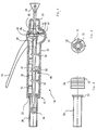
- the applicator 10 shown in FIG. 1 in a first embodiment has a housing 12 on which an actuating element designed as an actuating lever 14 is guided so as to be pivotable.
- the housing 12 also carries a sliding piston rod 16 and carries at its front end 18 a cartridge case 20 of a cartridge, not shown in detail, for holding dental material.
- the cartridge case 20 is detachably connected to the housing 12 via an adapter connection 22, in particular in the form of a bayonet catch.
- the piston rod 16 passes through the housing at its rear end 24 and ends there at a gripping handle 26.
- the gripping handle 26 allows the rod 16 to be manually retracted into an initial position in which the piston rod 16 is in the rightmost position in the drawing according to FIG. 1 extends.
- the applicator 10 has a locking tilting element 28 and an actuating tilting element 30.
- Both canting elements extend essentially annularly around the piston rod 16. In order to ensure the cant due to the inclined position, they each have an inner diameter that is somewhat larger than the outer diameter of the piston rod 16.
- the inner surface of the canting elements 28 and 30 is flat in a manner known per se and ends each with a rather sharp edge in order to ensure the desired clamping action when tilted.
- Both canting elements 28, 30 are resiliently preloaded by compression springs 32 and 34 in the rearward direction of the piston rod, that is to say in the direction of the gripping handle 26.
- the compression springs 32, 34 are each supported on their support projections 36, 38 of the housing 12 at their end remote from the tilting element 28, 30 and extend around the piston rod 16.
- the locking canting element 28 is further supported on one side in a canting element receptacle 40 on the housing 12. Due to the action of the compression spring 32, the locking tilting element 28 is tilted and thus blocks the movement of the piston rod 16 in the reverse direction. On the other hand, a - friction-loaded - movement of the piston rod in the forward direction is possible, since then the piston rod 16 takes the locking canting element 28 somewhat against the action of the compression spring 32 and reduces the canting force.
- a coupling rod 42 On the side opposite the receptacle 40, a coupling rod 42 also acts on the locking canting element 28, likewise against the action of the compression spring 32.
- the coupling rod 42 is supported at its other end via the actuating canting element 30 .
- the coupling rod 42 extends obliquely to the piston rod 16, it being understood that, instead of the embodiment shown, another force-transmitting device, for example also a sleeve, a longitudinal element or the like, is possible for transmitting the compressive force to the locking canting element 28.
- the length of the coupling rod 42 is dimensioned such that in the rest position of the actuating element 14, the coupling rod 42 presses on the locking canting element 28 such that it releases the piston rod 16.
- the piston rod 16 is thus freely movable.
- the actuation tilting element 30 extends in a similar manner Like the locking tilting element 28 around the piston rod 16. Accordingly, the actuating tilting element 30 is able to hold onto the piston rod 16 at least in one direction when it is tilted. While the locking tilting element 28 is supported in a receptacle 40 both in the forward direction and in the backward direction, the actuating tilting element lies only on one side against a support stop 44 of the housing. The support stop 44 supports the actuating tilting element 30 in the rearward direction.
- the actuating element 14 has a driver 46 which is fixedly connected to it and is intended for contact with the actuating tilting element 30.
- the actuating tilting element 30 has a contact surface facing in the rearward direction.
- the actuating element 14 is pivotally mounted on the housing 12.
- an axis of the actuating element can extend across the housing.
- the pivot axis of the pivot lever 14 extends approximately in the area of the coupling rod 42 and the actuating tilting element 30.
- the actuating element 14 also has a support point 50 for the coupling rod 42, on the opposite side of the lever 14 with respect to the pivot axis relative to the driver 46.
- the support point 50 thus moves in the reverse direction, so that the coupling rod 42 also moves in the reverse direction moves and the locking tilting element 28 locks according to the action of the compression spring 32.
- the actuation of the actuating element 14 from the rest position shown in Fig. 1 in a working position in which the lever 14 is pivoted counterclockwise and abuts the housing 12 or extends at least in the vicinity, causes that the actuating tilting element first the driver 46 canted and begins to move the piston rod 16 in the forward direction.
- the coupling rod 42 is relieved, so that the locking tilting element 28 begins to tilt.
- the locking tilting element is fully relieved, so that the piston rod 16 can only move forward, but not in the reverse direction.
- the movement of the actuating elements in the working direction is completed.
- the movement of the actuating element 14 can be initiated in the opposite direction. Due to the action of the compression spring 34, which has been pressed together by the joint advance of the actuating tilting element 30 and the piston rod 16, the actuating element 14 moves in the opposite direction with spring support.
- the coupling rod 42 does not initially act on the locking tilting element 28, so that the piston rod 16 is locked in the reverse direction and when the actuating element 14 is released, the actuating tilting element 30 slides along the piston rod 16 in the reverse direction. This takes place until the position of the actuating lever 14 is reached, in which the support point 50 activates the coupling rod 42, in particular pressurizes it.
- the position of the actuating element 14 at which the backward movement of the piston rod 16 begins can be adjusted by a suitable choice of the length of the coupling rod 42 in relation to the distance between the locking tilting element 28 and the support adapter 50.
- the backward movement clearly relieves the mass to be pressed, in order to reliably avoid re-pressing.
- the forward movement of the piston rod 16 minus the small backward movement to avoid re-pressing forms a stroke of the applicator 10 according to the invention.
- the cartridge case 20 can be seen in the state before it is inserted into the housing 12.
- the cartridge case has four adapter projections 50.
- the cartridge contains the viscous mass, in particular the tooth filling material, which can be expressed by the applicator 10 according to the invention.
- the piston rod with its punch 54 provided at the front end, presses on a piston of the cartridge, which thereby releases the tooth filling material, which in particular can be a light-curing tooth filling material.
- the housing 12 has a corrugation 56 on its outer circumference in the region of the front end, which serves to improve handling.
- the adapter connection 22 works in the manner of a bayonet lock.
- Adapter tabs 52 extend evenly around the circumference of the cartridge case 20 and are suitable for engaging in recesses 58, which are shaped accordingly, at the front end of the housing 12.
- the adapter projections are locked on the adapter connection 22, so that the cartridge case 20 is securely and rigidly locked on the housing 12.
- FIG. 4 An embodiment modified from the embodiment according to FIG. 1 can be seen from FIG. 4.
- the locking tilting element 28 and the actuating tilting element 30 are arranged one behind the other on the piston rod 16.
- the coupling rod 42 extends between the locking tilting element 28 and the area of the actuating tilting element 30. In the rest position shown in FIG. 4, the coupling rod 42 is unloaded, so that the locking tilting element 28 locks on the piston rod 16. In contrast to the embodiment according to FIG. 1, the piston rod 16 cannot therefore be moved freely in the rest position. In addition, there is no movement of the piston rod 16 when the actuating element 14 is relieved into the rest position, which is shown in FIG. 4.
- the actuating element 14 can be moved further in the direction of an arrow A in the opposite direction beyond the rest position, and reaches a release position there. In this position, it acts via the support point 50 in the manner of a two-armed lever on the coupling rod 42 and via the coupling rod 42 on the locking canting element 28 in a position in which the piston rod 16 is released.
- a driver 46 for the actuating tilting element 30 is designed as a correspondingly enlarged projecting surface on the actuating element 14.
- the actuating element 14 can be pivoted on the housing stored, stub axles, which are not visible in the drawing and extend up and down from the plane of the drawing, are mounted in the housing 12.
- the lever forming the actuating element is formed with two legs, the two legs converging in the region of the free end and that both legs laterally along the housing 12 up to the pivot axis 62 extend at which they pass through the housing 12 from the outside inwards and form the support point 50 and the driver 46.
- the entire path of movement of the adapter 10 according to the invention can be seen from FIG. 4 in the area of the cartridge case 20.
- the cartridge case 20 holds the highly viscous mass, not shown, in particular the tooth filling material.
- a piston 64 is adjacent to the housing 12. The piston 64 is moved a little in the working direction by each stroke generated by the actuation of the actuating element 14 until it is adjacent to the outlet end 66 of the cartridge 20. Each time lever 14 is actuated, some tooth filling material is dispensed at exit end 66.
- the piston rod 16 can only be moved exactly up to the position at which the piston 64 has reached its end position.
- the paragraph 68 shown in FIG. 1 is provided, which in this position of the piston 64 comes straight into the area of the actuating tilting element 30. Because of the reduced diameter of the piston rod 16 following the shoulder 68, the actuating tilting element 30 then no longer engages, so that further pressing of the lever 14 does not result in an advance of the piston rod 16.
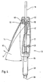
- FIG. 5 Another embodiment of the applicator according to the invention 10 can be seen from FIG. 5.
- the pivotable guidance of the actuating element 14 is ensured by guide surfaces 47 and 48 which are formed on the pivotable actuating lever 14 and the housing 12.
- the guide surfaces 47 and 48 have a common radius, so that the lever 14 can be pivoted about the pivot axis 62 without it being necessary for stub axles to pass through the housing 12.
- the lever 14 extends in the region of the guide surfaces on both sides of the piston rod 16 and forms both the driver 46 for the actuating tilting element 30 and the support point 50 for the coupling rod 42.
- the coupling rod 42 is additionally slidably supported on the housing 12, specifically by U-shaped receptacles 68 and 70. In this exemplary embodiment as well, the coupling rod 42 extends obliquely over the piston rod 16.
- the arrangement of the receptacle 68 for the coupling rod 42 and the bearing point 36 for the locking canting element 28 is interchanged.
- the coupling rod 42 then extends essentially parallel to the piston rod 16.
- FIG. 6 shows an enlarged detail of the embodiment according to FIG. 5, which shows the transition to the mounting of the coupling rod 42.
- the coupling rod 42 has an adjusting device 72.
- the effective distance between the locking canting element 28 and the pressure surface or support point 50 or the pretensioning of the coupling rod 42 can be set via the adjusting device 72, which can be designed as a knurled nut.
- This points the end of the coupling rod 42 has an external thread 74 and the knurled nut 72 has a corresponding internal thread.
- the knurled nut 72 can be actuated via an opening 76 in the housing.
- the knurled nut 72 is preferably a self-locking nut and its area is covered with a cover, not shown, so that only an adjustment is provided for the setting of the applicator.
- the lever 14 can also be pivoted into a release position by pulling it away from the housing 12. In this position, the pressure surface 50 presses on the actuating device 72 and thus the coupling rod 42 and at the same time also on the actuating tilting element 30, which is lifted off the support 44 fixed to the housing. Both tilting elements 30 and 28 release the piston rod 16 so that it can be moved freely.
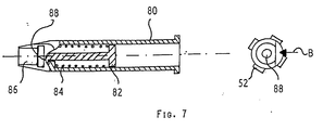
- connection of a spring-loaded adapter is provided, as can be seen in FIG. 7.
- the adapter 80 is provided for engagement on the adapter connection 22 of the housing and has a piston 82 which is spring-loaded in the rearward direction of the piston rod, not shown.
- the piston rod 16 is intended to rest against the piston 82 with its punch 54 or its front end. Due to the spring loading by the compression spring 84, the piston rod is pushed back into its starting position when the movement of the piston rod 16 is released, for example when the lever 14 is actuated into the release position, without the need for manual retraction.
- the adapter 80 is designed to receive a cartridge on its cartridge receptacle 86.
- the cartridge receptacle is open on one side, and a cartridge (not shown) with tooth filling material can be snapped into the adapter 80 made of elastic plastic by being pushed in from the direction of arrow B.
- the piston 82 has a projection 88 at its front end, via which it is held captively in the adapter 80.
- the piston rod 10 is provided with micro-toothing in the engagement area of the actuating tilting element 30.
- the micro-toothing preferably has a sawtooth profile, the depth being approximately 20-100 micrometers, preferably approximately 50 micrometers.
- micro toothing can also be provided in the area of the locking / tilting element (28) if required. Furthermore, it may be simpler for manufacturing reasons to provide the entire piston rod 16 with the micro toothing, which does not impair the function of the solution according to the invention.
Landscapes
- Health & Medical Sciences (AREA)
- General Health & Medical Sciences (AREA)
- Dentistry (AREA)
- Epidemiology (AREA)
- Life Sciences & Earth Sciences (AREA)
- Animal Behavior & Ethology (AREA)
- Oral & Maxillofacial Surgery (AREA)
- Public Health (AREA)
- Veterinary Medicine (AREA)
- Engineering & Computer Science (AREA)
- Mechanical Engineering (AREA)
- Dental Tools And Instruments Or Auxiliary Dental Instruments (AREA)
- Coating Apparatus (AREA)
- Massaging Devices (AREA)
Abstract
Description
Die Erfindung betrifft einen Applikator gemäß dem Oberbegriff von Anspruch 1.The invention relates to an applicator according to the preamble of claim 1.
Ein derartiger Applikator für hochviskose Massen, insbesondere für Zahnfüllmaterial, ist beispielsweise aus der DE-OS-36 07 384 bekannt. Dieser Applikator weist einen Pistolengriff mit einem Drücker auf, der über eine Antriebsmechanik bei jeder Betätigung Zahnfüllmaterial abgibt. Wenn die Patrone mit Zahnfüllmaterial leer ist, kann eine Kolbenstange über eine Freigabestange gelöst und zurückgeschoben werden, so daß eine neue, gefüllte Patrone einsetzbar ist.Such an applicator for highly viscous compositions, in particular for tooth filling material, is known for example from DE-OS-36 07 384. This applicator has a pistol grip with a pusher, which dispenses tooth filling material with each actuation via a drive mechanism. If the cartridge with tooth filling material is empty, a piston rod can be released and pushed back via a release rod, so that a new, filled cartridge can be inserted.
Zahnfüllmaterialien müssen in der Regel exakt dosiert werden, so daß es wünschenswert ist, daß die bei der Betätigung des Drückers abgegebene Masse konstant ist. Insbesondere soll nach der Betätigung kein weiteres Ausfließen der pastösen und ziemlich hochviskosen Masse wie des Zahnfüllmaterials erfolgen, zumal dies häufig mit Verunreinigungen verbunden ist. Bei der aus der DE-OS-36 07 384 bekannten Lösung ist es zum Vermeiden der Nachpressung vorgesehen, daß bei Betätigung des Drückers oder Betätigungselements anschließend an den Austreibvorgang eine Entlastung der Kolbenstange über einen speziellen Entlastungshebel, der einstückig mit dem Betätigungshebel verbunden ist und auf ein Sperr-Verkantungselement wirkt, vorgenommen wird.Tooth filling materials usually have to be dosed exactly, so that it is desirable that the mass given off when the trigger is actuated is constant. In particular, no further outflow of the pasty and rather highly viscous mass such as the tooth filling material should take place after the actuation, especially since this is often associated with contamination. In the solution known from DE-OS-36 07 384, it is provided to avoid the repressing that when the pusher or actuating element is actuated, the piston rod is relieved after the expulsion process via a special relief lever which is connected in one piece to the actuating lever and on a locking tilting element acts, is made.
Nachteilig ist bei dieser Lösung, daß eine Entlastung nur dann vorgenommen wird, wenn der Drücker vollständig eingedrückt wird. Andererseits neigt die Bedienperson nach dem erfolgten Ausdrücken in dem gewünschten Maße dazu, nicht noch weitere Kraft aufzubringen, um den Drücker vollständig einzudrücken, zumal der gewünschte Erfolg bereits erzielt erscheint. Daher ist es bei dieser Lösung nicht sichergestellt, daß ein Nachpressen vermieden wird.The disadvantage of this solution is that the pressure is only relieved when the handle is fully pushed in. On the other hand, the operator tends to the desired extent after the expressions have been made, not any more Applying strength to fully depress the pusher, especially since the desired success already appears to be achieved. It is therefore not ensured with this solution that re-pressing is avoided.
Demgegenüber liegt der Erfindung die Aufgabe Zugrunde, einen Applikator gemäß dem Oberbegriff von Anspruch 1 zu schaffen, der ein Nachpressen der zu applizierenden Masse sicher vermeidet.In contrast, the invention is based on the object of creating an applicator according to the preamble of claim 1 which reliably avoids re-pressing the mass to be applied.
Diese Aufgabe wird erfindungsgemäß durch Anspruch 1 gelöst. Vorteilhafte Weiterbildungen ergeben sich aus den Unteransprüchen.This object is achieved by claim 1. Advantageous further developments result from the subclaims.
Besonders günstig bei dem erfindungsgemäßen Applikator oder der erfindungsgemäßen Ausdrückvorrichtung ist die automatische Rückstellung in eine Entlastungsstellung für die auszudrückende viskose Masse, und zwar unabhängig davon, ob das Betätigungselement ganz oder teilweise über seinen Betätigungsweg bewegt wird. In diesem Zusammenhang ist es besonders vorteilhaft, daß die Freigabe durch die erfindungsgemäße Koppelstange beim Lösen des Betätigungselements erfolgt.The automatic return to a relief position for the viscous mass to be expressed is particularly favorable with the applicator according to the invention or the push-out device according to the invention, regardless of whether the actuating element is moved in whole or in part via its actuating path. In this context, it is particularly advantageous that the release by the coupling rod according to the invention takes place when the actuating element is released.
Aufgrund der Hebelwirkung des Betätigungselements- oder Hebels wird eine Kraftübersetzung von beispielsweise 5:1 erzeugt, so daß die Ausdrückkraft beispielsweise fünf mal größer als die Betätigungskraft des Betätigungshebels ist. Die Ausdrückkraft wird von der Kolbenstange, den Verkantungselementen und dem Gehäuse aufgenommen, die je eine gewisse Elastizität aufweisen, so daß sich ein geringer Rückfederweg beim Lösen der Betätigungskraft ergibt. Auch dieser wird erfindungsgemäß sicher berücksichtigt, so daß die in dem Applikator eingesetzte Patrone oder eine über einen Adapter eingesetzte Kartusche vorspannungsfrei verbleibt, wenn das Betätigungselement sich in der Ruhestellung befindet. Erfindungsgemäß ist es demnach vorgesehen, daß auch die gewisse Elastizität der Arbeitselemente bei der Betätigung unkritisch ist.Due to the lever action of the actuating element or lever, a force transmission of, for example, 5: 1 is generated, so that the push-out force is, for example, five times greater than the actuating force of the actuating lever. The push-out force is absorbed by the piston rod, the tilting elements and the housing, each of which has a certain elasticity, so that there is a small springback when the actuating force is released. This is also safely taken into account according to the invention, so that the cartridge inserted in the applicator or a cartridge inserted via an adapter remains free of bias when the actuating element is in the rest position. According to the invention, it is therefore provided that the certain elasticity of the working elements is uncritical when actuated.
Gemäß einer ersten Ausführungsform ist die Kolbenstange in der Ruhestellung des Betätigungselements frei beweglich. Sie kann demnach zum Beladen mit einer neuen Patrone ohne weiteres von Hand zurückgezogen werden. Bei dieser Ausführungsform ist die Länge der Koppelstange so bemessen, daß sie in Ruhestellung des Betätigungselements unter Druck steht und das Sperr-Verkantungselement freigibt. Erst beim Lösen des Betätigungselements nach der Bewegung in die Arbeitsstellung greift das Sperr-Verkantungselement, jedoch nur über einen Teil der Bewegung des Betätigungselements in Gegenrichtung zur Arbeitsrichtung, so daß während des verbleibenden Teils der Bewegung des Betätigungselements das Sperr-Verkantungselement nicht greift und aufgrund der Reibung zwischen dem Verkantungselement und dem Betätigungselement eine kleine Rückwärtsbewegung der Kolbenstange, also eine Bewegung in Rückwärtsrichtung erfolgt.According to a first embodiment, the piston rod is freely movable in the rest position of the actuating element. It can therefore easily be pulled back by hand to load a new cartridge. In this embodiment, the length of the coupling rod is dimensioned such that it is under pressure in the rest position of the actuating element and releases the locking tilting element. Only when the actuating element is released after the movement into the working position does the locking-tilting element engage, but only over part of the movement of the actuating element in the opposite direction to the working direction, so that during the remaining part of the movement of the actuating element the locking-tilting element does not engage and because of the Friction between the tilting element and the actuating element causes a small backward movement of the piston rod, that is to say a movement in the backward direction.
Bei einer zweiten Ausführungsform der Erfindung ist demgegenüber vorgesehen, daß die Länge der Koppelstange so ausgelegt ist, daß das Sperr-Verkantungselement in der Ruhestellung des Betätigungselements noch greift, also gegen die Kolbenstange verkantet. Auch bei dieser Ausführungsform läßt sich durch eine geeignete Einstellung ein sicheres Entlasten und gegebenenfalls auch eine kleine Bewegung der Kolbenstange in Rückwärtsrichtung sicherstellen. Zum vollständigen Bewegen der Kolbenstange in Rückwärtsrichtung - zum Austauschen der Patrone oder der Kartusche - ist es bei dieser Lösung vorgesehen, daß das Betätigungselement über die Ruhestellung hinaus in eine Lösestellung bewegbar ist, in welcher es auf die Kolbenstange wirkt, so daß diese das Sperr-Verkantungselement entgegen seiner Federbelastung in eine Freigabeposition bringt, in welcher die Kolbenstange freigegeben ist.In a second embodiment of the invention, on the other hand, it is provided that the length of the coupling rod is designed so that the locking canting element still engages in the rest position of the actuating element, that is to say canted against the piston rod. In this embodiment, too, reliable relief and possibly also a small movement of the piston rod in the backward direction can be ensured by a suitable setting. For complete movement of the piston rod in the reverse direction - for replacing the cartridge or the cartridge - it is provided in this solution that the actuating element can be moved beyond the rest position into a release position in which it acts on the piston rod so that it blocks the Tilting element brings against its spring load in a release position in which the piston rod is released.
Gemäß einer weiteren bevorzugten Ausgestaltung ist eine Stellvorrichtung vorgesehen, mit welcher der über die Koppelstange eingestellte Abstand zwischen einer entsprechenden Fläche des Betätigungselements und dem Sperr-Verkantungselement einstellbar ist. Die Stellvorrichtung kann in beliebiger geeigneter Weise ausgebildet sein, beispielsweise als auf die Koppelstange aufgebrachte, von außen verstellbare Rändelmutter, oder als verschiebbare Lagerstelle des Sperr-Verkantungselements an dem Gehäuse. Es ist auch möglich, mit einer weiteren Ausgestaltung des erfindungsgemäßen Applikators je nach Stellung der Stellvorrichtung eine Gegenbewegung der Kolbenstange in Rückwärtsrichtung kurz vor Erreichen der Ruhestellung des Betätigungselements einzuleiten oder eine reine Entlastung der Patrone oder Kartusche mit der hochviskosen Masse sicherzustellen.According to a further preferred embodiment, an actuating device is provided with which the over the coupling rod set distance between a corresponding surface of the actuating element and the locking tilting element is adjustable. The actuating device can be designed in any suitable manner, for example as a knurled nut which is attached to the coupling rod and can be adjusted from the outside, or as a displaceable bearing point of the locking canting element on the housing. It is also possible, with a further embodiment of the applicator according to the invention, to initiate a counter-movement of the piston rod in the reverse direction shortly before the actuating element is at rest, depending on the position of the adjusting device, or to ensure that the cartridge or cartridge with the highly viscous mass is relieved of pressure.
Es ist bevorzugt, daß der erfindungsgemäße Applikator die Patrone oder Kartusche mit der hochviskosen Masse in einer Mehrzahl von Hüben ausdrückt. Wenn eine Kartusche mit lichthärtendem Material über einen entsprechenden Adapter verwendet wird, kann es beispielsweise vorgesehen sein, daß die Kolbenstange mit etwa drei bis zwanzig Hüben, bevorzugt fünf bis zwölf und insbesondere etwa acht oder neun Hüben die Kartusche ausdrückt, so daß der Hub der Kolbenstange bei jeder vollständigen Bewegung des Betätigungselements und einer angenommenen Füllänge der Kartusche von 1,5 cm 0,8 bis 5 mm und insbesondere etwa 1,9 mm beträgt. Es versteht sich jedoch, daß die Anzahl der möglichen Hübe bei vollständiger Bewegung der Kolbenstange von einem Ende zum anderen in weiten Bereichen an die Erfordernisse anpaßbar ist. Beispielsweise kann die Kolbenstange auch einen erheblich vergrößerten Bewegungsweg von beispielsweise auch 10 cm aufweisen, wenn eine entsprechend große Patrone bedient werden soll.It is preferred that the applicator according to the invention express the cartridge or cartridge with the highly viscous mass in a plurality of strokes. If a cartridge with light-curing material is used via a corresponding adapter, it can be provided, for example, that the piston rod expresses the cartridge with approximately three to twenty strokes, preferably five to twelve and in particular approximately eight or nine strokes, so that the stroke of the piston rod with each complete movement of the actuating element and an assumed filling length of the cartridge of 1.5 cm is 0.8 to 5 mm and in particular approximately 1.9 mm. However, it is understood that the number of possible strokes can be adapted to the requirements in a wide range with complete movement of the piston rod from one end to the other. For example, the piston rod can also have a considerably increased movement path of, for example, also 10 cm if a correspondingly large cartridge is to be operated.
Auch das Übersetzungsverhältnis des als Betätigungselement verwendeten Hebels läßt sich in weiten Bereichen an die Erfordernisse anpassen. Bei einem Hub von 4 mm kann es beispielsweise vorgesehen sein, daß das freie Ende des Betätigungshebels um etwa 4 cm bewegt werden muß, so daß insofern ein Bewegungs-Untersetzungs- bzw. ein Kraft-Übersetzungs-Verhältnis von 1:10 bzw. 10:1 vorliegt.The transmission ratio of the lever used as the actuating element can also be adapted to the requirements in a wide range. With a stroke of 4 mm, it can be provided, for example, that the free end of the actuating lever must be moved by about 4 cm, so that there is a movement reduction ratio or a force transmission ratio of 1:10 or 10: 1.
Die erfindungsgemäße Lösung ermöglicht trotz dieses guten Übersetzungsverhältnisses eine relativ kompakte und vor allem ergonomische Bauweise. Die schrägstehende Ruhestellung des Betätigungshebels, der in Vorwärtsrichtung der Kolbenstange weist und sich zum Gehäuse hin verschwenken läßt, um einen Arbeitshub, also eine Bewegung der Kolbenstange in Vorwärtsrichtung zu erzeugen, ermöglicht es beispielsweise, das vordere Ende des Gehäuses oder gegebenenfalls die Patronenhülse oder den Adapter mit zwei oder drei Fingern zu umgreifen, während der Daumen in Rückwärtsrichtung der Kolbenstange weist und das Gehäuse an einer geeigneten Stelle gegenstützt, und dann beispielsweise mit dem zeige- oder Mittelfinger das Betätigungselement in dem gewünschten Ausmaß zu betätigen. Diese Greifposition ermöglicht eine ruhige Handhabung ohne große Bewegung des Austrittsendes in Folge der Betätigung des Betätigungshebels. Überraschend ist die Betätigung bei dieser Greifposition noch konstanter und wackelsicherer als bei Verwendung einer Ausdrückvorrichtung mit Pistolengriff, wie sie an sich bekannt geworden ist, obwohl der erfindungsgemäße Applikator erheblich kleiner baut und auch ein geringeres Gewicht aufweist, so daß ein ermüdungsarmes Arbeiten möglich ist.Despite this good transmission ratio, the solution according to the invention enables a relatively compact and, above all, ergonomic design. The inclined rest position of the actuating lever, which points in the forward direction of the piston rod and can be pivoted toward the housing in order to produce a working stroke, that is to say a movement of the piston rod in the forward direction, makes it possible, for example, for the front end of the housing or, if appropriate, the cartridge case or the adapter to grasp with two or three fingers, while the thumb points in the rearward direction of the piston rod and supports the housing at a suitable location, and then, for example, to actuate the actuating element to the desired extent with the index or middle finger. This gripping position enables quiet handling without a large movement of the outlet end as a result of the actuation of the actuation lever. Surprisingly, the actuation in this gripping position is even more constant and shake-proof than when using an ejection device with a pistol grip, as has become known per se, although the applicator according to the invention is considerably smaller and also lighter in weight, so that fatigue-free working is possible.
Anstelle dieser Greifposition ist es auch möglich, das Gehäuse mit vier Fingern zu umgreifen und den Daumen auf die Spitze oder das freie Ende des Betätigungshebels wirken zu lassen. Auch diese Position ermöglicht eine ziemlich ruhige Bedienung des erfindungsgemäßen Applikators, und zwar sowohl, wenn der Applikator mit seiner Austreiböffnung nach oben, als auch wenn er nach unten aus der geschlossenen Hand herausragt.Instead of this gripping position, it is also possible to grip the housing with four fingers and let the thumb act on the tip or the free end of the actuating lever. This position also enables the applicator according to the invention to be operated fairly quietly, both when the applicator has its expulsion opening upwards and when it protrudes downwards from the closed hand.
Erfindungsgemäß besonders günstig ist es, daß die in einer Patronenhülse aufgenommene Patrone oder der Adapter zur Aufnahme der Kartusche über eine Rastvorrichtung wie einen Bajonettverschluß mit dem Gehäuse verbunden ist und dieses verlängert. Dann weist der gesamte Applikator im wesentlichen den Aufbau eines Stiftes auf, und die noch verbleibende Reserve der Patrone oder der Kartusche ist über eine Markierung gut ablesbar, die sich an dem hinteren Ende der Kolbenstange befindet, das sich nach hinten aus dem Gehäuse heraus erstreckt.According to the invention, it is particularly favorable that the cartridge accommodated in a cartridge case or the adapter for receiving it the cartridge is connected to the housing via a locking device such as a bayonet lock and extends it. Then the entire applicator essentially has the structure of a pen, and the remaining reserve of the cartridge or the cartridge can be easily read via a marking which is located at the rear end of the piston rod, which extends rearward out of the housing.
Der Adapter kann bei Bedarf mit einer ziemlich weichen Rückholfeder versehen sein, die in Richtung der Entlastung der Patrone wirkt und bei Betätigung des Betätigungselements in die Lösestellung dazu führt, daß die Kolbenstange automatisch in ihre Ausgangsposition zurückgeschoben wird, so daß eine neue Kartusche einsetzbar ist. Diese Kraft der Rückholfeder ist bevorzugt jedoch so gering, daß sie nicht ausreicht, die Kolbenstange bei Ruhestellung des Betätigungselements in ihre Ausgangsstellung zurückzuschieben, sondern lediglich eine Entlastung der Kartusche nach jedem Hub zu gewährleisten.If necessary, the adapter can be provided with a fairly soft return spring which acts in the direction of relieving the load on the cartridge and, when the actuating element is actuated into the release position, causes the piston rod to be automatically pushed back into its starting position, so that a new cartridge can be inserted. However, this force of the return spring is preferably so low that it is not sufficient to push the piston rod back into its starting position when the actuating element is at rest, but only to ensure relief of the cartridge after each stroke.
Weitere Einzelheiten, Merkmale und Vorteile ergeben sich aus der nachstehenden Beschreibung mehrerer Ausführungsbeispiele anhand der Zeichnung.Further details, features and advantages result from the following description of several exemplary embodiments with reference to the drawing.
Es zeigen:
- Fig. 1
- eine schematisisierte Schnittansicht einer Ausführungsform eines erfindungsgemäßen Applikators;
- Fig. 2
- eine Ansicht des vorderen Endes des Applikators mit von diesem getrennter Patronenhülse;
- Fig. 3
- eine Vorderansicht des vorderen Endes des Applikators, wobei die Patronenhülse entfernt ist;
- Fig. 4
- eine schematische Ansicht einer weiteren Ausführungsform des erfindungsgemäßen Applikators;
- Fig. 5
- eine Schnittansicht eines Teils einer weiteren Ausführungsform eines erfindungsgemäßen Applikators;
- Fig. 6
- eine Ausschnittvergrößerung zu Fig. 5; und
- Fig. 7
- eine teilweise aufgebrochene Ansicht eines Adapters für einen erfindungsgemäßen Applikator.
- Fig. 1
- a schematic sectional view of an embodiment of an applicator according to the invention;
- Fig. 2
- a view of the front end of the applicator with this separate cartridge case;
- Fig. 3
- a front view of the front end of the applicator with the cartridge case removed;
- Fig. 4
- a schematic view of a further embodiment of the applicator according to the invention;
- Fig. 5
- a sectional view of part of a further embodiment of an applicator according to the invention;
- Fig. 6
- an enlarged detail of Fig. 5; and
- Fig. 7
- a partially broken away view of an adapter for an applicator according to the invention.
Der in Fig. 1 in einer ersten Ausführungsform dargestellte Applikator 10 weist ein Gehäuse 12 auf, an dem ein als Betätigungshebel 14 ausgebildetes Betätigungselement schwenkbeweglich geführt ist. Das Gehäuse 12 führt ferner eine schiebebewegliche gelagerte Kolbenstange 16 und trägt an seinem vorderen Ende 18 eine Patronenhülse 20 einer nicht im einzelnen dargestellten Patrone für die Aufnahme von zahntechnischem Material. Die Patronenhülse 20 ist lösbar über einen Adapteranschluß 22, insbesondere in Form eines Bajonettverschlusses, mit dem Gehäuse 12 verbunden.The
Die Kolbenstange 16 durchtritt das Gehäuse an dessen rückwärtigen Ende 24 und endet dort an einer Greifhandhabe 26. Die Greifhandhabe 26 erlaubt das manuelle Zurückziehen der Stange 16 in eine Ausgangsstellung, in welcher sich die Kolbenstange 16 in der in der Zeichnung gemäß Fig. 1 rechtesten Stellung erstreckt.The
Der erfindungsgemäße Applikator 10 weist ein Sperr-Verkantungselement 28 und ein Betätigungs-Verkantungselement 30 auf. Beide Verkantungselemente erstrecken sich im wesentlichen ringförmig um die Kolbenstange 16. Um die Verkantung infolge der Schrägstellung sicherzustellen, weisen sie je einen Innendurchmesser auf, der etwas größer als der Außendurchmesser der Kolbenstange 16 ist. Die Innenfläche der Verkantungselemente 28 und 30 ist in an sich bekannter Weise flach und endet je ziemlich scharfkantig, um die erwünschte Klemmwirkung bei Schrägstellung zu gewährleisten.The
Beide Verkantungselemente 28, 30 sind durch Druckfedern 32 bzw. 34 in Rückwärtsrichtung der Kolbenstange, also in Richtung auf die Greifhandhabe 26, federnd vorbelastet. Die Druckfedern 32, 34 sind an ihrem von den Verkantungselement 28, 30 entfernten Ende je an Stützvorsprüngen 36, 38 des Gehäuses 12 abgestützt und erstrecken sich um die Kolbenstange 16.Both
Das Sperr-Verkantungselement 28 ist ferner einseitig in einer Verkantungselement-Aufnahme 40 an dem Gehäuse 12 abgestützt. Durch die Wirkung der Druckfeder 32 wird das Sperr-Verkantungselement 28 verkantet und sperrt damit die Bewegung der Kolbenstange 16 in Rückwärtsrichtung. Hingegen ist eine - reibungsbelastete - Bewegung der Kolbenstange in Vorwärtsrichtung möglich, da dann die Kolbenstange 16 das Sperr-Verkantungselement 28 gegen die Wirkung der Druckfeder 32 etwas mitnimmt und die Verkantungskraft reduziert.The locking
An der gegenüber der Aufnahme 40 gegenüberliegenden Seite wirkt zudem eine Koppelstange 42 auf das Sperr-Verkantungselement 28 ebenfalls gegen die Wirkung der Druckfeder 32. In dem dargestellten Ausführungsbeispiel gemäß Fig. 1 ist die Koppelstange 42 an ihrem anderen Ende über das Betätigungs-Verkantungselement 30 abgestützt. Die Koppelstange 42 erstreckt sich schräg zur Kolbenstange 16, wobei es sich versteht, daß anstelle der dargestellten Ausführung auch eine andere kraftübertragende Vorrichtung, beispielsweise auch eine Hülse, ein Längselement oder dergleichen für die Übertragung der Druckkraft auf das Sperr-Verkantungselement 28 möglich ist.On the side opposite the
In dem dargestellten Ausführungsbeispiel ist die Länge der Koppelstange 42 so bemessen, daß in der Ruhestellung des Betätigungselements 14 die Koppelstange 42 derart auf Sperr-Verkantungselement 28 drückt, daß es die Kolbenstange 16 freigibt. Die Kolbenstange 16 ist damit frei beweglich.In the illustrated embodiment, the length of the
Das Betätigungs-Verkantungselement 30 erstreckt sich in ähnlicher Weise wie das Sperr-Verkantungselement 28 um die Kolbenstange 16. Entsprechend ist das Betätigungs-Verkantungselement 30 in der Lage, bei Verkantung gegenüber der Kolbenstange 16 auf dieser mindestens in einer Richtung festzuhalten. Während das Sperr-Verkantungselement 28 in einer Aufnahme 40 sowohl in Vorwärtsrichtung als auch in Rückwärtsrichtung abgestützt ist, liegt das Betätigungs-Verkantungselement lediglich einseitig an einem Stützanschlag 44 des Gehäuses an. Der Stützanschlag 44 stützt das Betätigungs-Verkantungselement 30 in Rückwärtsrichtung ab.The
Das Betätigungselement 14 weist einen Mitnehmer 46 auf, der fest mit ihm verbunden ist und für die Anlage an dem Betätigungs-Verkantungselement 30 bestimmt ist. Hierzu weist das Betätigungs-Verkantungselement 30 eine in Rückwärtsrichtung gewandte Anlagefläche auf. Durch Betätigung des Betätigungselements 14 gegen den Uhrzeigersinn - bezogen auf die Darstellung gemäß Fig. 1 - wird der Mitnehmer 46 in Vorwärtsrichtung bewegt und wirkt hierdurch auf das Betätigungs-Verkantungselement 30, und zwar einseitig. Da die Druckfeder 34 in Gegenrichtung wirkt, verkantet das Betätigungs-Verkantungselement 30 und ist in der Lage, die Kolbenstange 16 in Vorwärtsrichtung zu bewegen.The
Das Betätigungselement 14 ist an dem Gehäuse 12 schwenkbeweglich gelagert. Hierzu kann sich eine Achse des Betätigungselements quer durch das Gehäuse erstrecken. Anstelle dessen ist es jedoch auch möglich, entsprechend geformte Führungsflächen 47, 48 zwischen dem Gehäuse und dem Betätigungselement 14 vorzusehen, an welchen das Betätigungselement gleitet, so daß die erwünschte Schwenkfunktion sichergestellt ist.The
Bei dem dargestellten Ausführungsbeispiel gemäß Fig. 1 erstreckt sich die Schwenkachse des Schwenkhebels 14 etwa im Bereich der Koppelstange 42 und des Betätigungs-Verkantungselements 30. Das Betätigungselement 14 weist ferner eine Stützstelle 50 für die Koppelstange 42 auf, und zwar an der bezogen auf die Schwenkachse gegenüber dem Mitnehmer 46 gegenüberliegenden Seite des Hebels 14. Bei Bewegung des Mitnehmers 46 in Vorwärtsrichtung bewegt sich somit die Stützstelle 50 in Rückwärtsrichtung, so daß die Koppelstange 42 sich ebenfalls in Rückwärtsrichtung bewegt und das Sperr-Verkantungselement 28 entsprechend der Wirkung der Druckfeder 32 sperrt.In the exemplary embodiment shown in FIG. 1, the pivot axis of the
Die Betätigung des Betätigungselements 14 aus der in Fig. 1 dargestellten Ruhestellung in eine Arbeitsstellung, in welcher der Hebel 14 gegen den Uhrzeigersinn geschwenkt ist und an dem Gehäuse 12 anliegt oder sich zumindest in dessen Nähe erstreckt, bewirkt, daß zunächst das Betätigungs-Verkantungselement über den Mitnehmer 46 verkantet und mit der Bewegung der Kolbenstange 16 in Vorwärtsrichtung beginnt. Zugleich wird die Koppelstange 42 entlastet, so daß das Sperr-Verkantungselement 28 zu verkanten beginnt. Sobald die Bewegung gegen den Uhrzeigersinn beginnt, wird Sperr-Verkantungselement voll entlastet, so daß die Kolbenstange 16 sich lediglich vorwärts bewegen kann, nicht jedoch in Rückwärtsrichtung.The actuation of the
Mit dem Erreichen der Arbeitsstellung ist die Bewegung der Betätigungselemente in Arbeitsrichtung abgeschlossen. In dieser Stellung kann die Bewegung des Betätigungselements 14 in die Gegenrichtung eingeleitet werden. Aufgrund der Wirkung der Druckfeder 34, die durch den gemeinsamen Vorschub von Betätigungs-Verkantungselement 30 und Kolbenstange 16 zusammen gedrückt worden ist, erfolgt die Bewegung des Betätigungselements 14 in Gegenrichtung federunterstützt. Die Koppelstange 42 wirkt zunächst noch nicht auf das Sperr-Verkantungselement 28, so daß die Kolbenstange 16 in Rückwärtsrichtung gesperrt wird und beim Lösen des Betätigungselements 14 das Betätigungs-Verkantungselement 30 in Rückwärtsrichtung an der Kolbenstange 16 entlang gleitet. Dies geschieht, bis die Position des Betätigungshebels 14 erreicht ist, in der die Stützstelle 50 die Koppelstange 42 aktiviert, insbesondere mit Druck beaufschlagt. Hierdurch wird das Sperr-Verkantungselement 28 entsperrt und gibt damit die Kolbenstange 16 frei. Aufgrund der Reibung zwischen dem noch verkanteten Betätigungs-Verkantungselement 30 und der Kolbenstange 16 wird diese nun leicht in Rückwärtsrichtung bewegt, bis die in Fig. 1 dargestellte Ruhestellung des Betätigungselements 14 erreicht ist.When the working position is reached, the movement of the actuating elements in the working direction is completed. In this position, the movement of the
Es versteht sich, daß durch eine geeignete Wahl der Länge der Koppelstange 42 im Verhältnis zum Abstand zwischen dem Sperr-Verkantungselement 28 und der Stützadapter 50 die Stellung des Betätigungselements 14 einstellbar ist, an welcher die Rückwärtsbewegung der Kolbenstange 16 beginnt. Die Rückwärtsbewegung dient der eindeutigen Entlastung der auszupressenden Masse, um so ein Nachpressen sicher zu vermeiden.It is understood that the position of the
Die Vorwärtsbewegung der Kolbenstange 16 abzüglich der kleinen Rückwärtsbewegung zur Vermeidung des Nachpressens bildet einen Hub des erfindungsgemäßen Applikators 10.The forward movement of the
Aus Fig. 2 ist die Patronenhülse 20 in dem Zustand ersichtlich, bevor sie in das Gehäuse 12 eingesetzt ist. Die Patronenhülse weist an ihrem dem Gehäuse 12 zugewandten Ende vier Adaptervorsprünge 50 auf. Die Patrone enthält die zähviskose Masse, insbesondere das Zahnfüllmaterial, das durch den erfindungsgemäßen Applikator 10 ausdrückbar ist. Hierzu drückt die Kolbenstange mit ihrem an dem vorderen Ende vorgesehenen Stempel 54 auf einen Kolben der Patrone, die hierdurch das Zahnfüllmaterial, das insbesondere ein lichthärtendes Zahnfüllmaterial sein kann, abgibt.2, the
Wie aus Fig. 2 ebenfalls ersichtlich ist, weist das Gehäuse 12 an seinem Außenumfang im Bereich des vorderen Endes eine Riffelung 56 auf, die Verbesserung der Handhabbarkeit dient.As can also be seen from FIG. 2, the
Aus Fig. 3 ist ersichtlich, daß der Adapteranschluß 22 nach der Art eines Bajonettverschlusses arbeitet. Adaptervorsprünge 52 erstrecken sich gleichmäßig verteilt um den Umfang der Patronenhülse 20 und sind dafür geeignet, in Ausnehmungen 58, die entsprechend geformt sind, an dem vorderen Ende des Gehäuses 12 einzugreifen. Durch eine Verdrehung der Patronenhülse um beispielsweise knapp 45° erfolgt eine Verrastung der Adaptervorsprünge an dem Adapteranschluß 22, so daß die Patronenhülse 20 an dem Gehäuse 12 sicher und biegesteif arretiert ist.From Fig. 3 it can be seen that the
Eine gegenüber der Ausführungsform gemäß Fig. 1 abgeänderte Ausführungsform ist aus Fig. 4 ersichtlich. Bei dieser Ausführungsform sind das Sperr-Verkantungselement 28 und das Betätigungs-Verkantungselement 30 hintereinander auf der Kolbenstange 16 angeordnet. Die Koppelstange 42 erstreckt sich zwischen dem Sperr-Verkantungselement 28 und dem Bereich des Betätigungs-Verkantungselements 30. In der in Fig. 4 dargestellten Ruhestellung ist die Koppelstange 42 unbelastet, so daß das Sperr-Verkantungselement 28 auf der Kolbenstange 16 sperrt. Im Unterschied zur Ausführungsform gemäß Fig. 1 läßt sich daher die Kolbenstange 16 in der Ruhestellung nicht frei bewegen. Zudem findet keine Bewegung der Kolbenstange 16 bei Entlastung des Betätigungselements 14 in die Ruhestellung statt, die in Fig. 4 dargestellt ist. Das Betätigungselement 14 läßt sich jedoch in Richtung eines Pfeiles A weiter in Gegenrichtung über die Ruhestellung hinaus bewegen, und erreicht dort eine Lösestellung. In dieser Stellung wirkt es über die Stützstelle 50 nach der Art eines zweiarmigen Hebels auf die Koppelstange 42 und über die Koppelstange 42 auf das Sperr-Verkantungselement 28 in eine Stellung, in welcher die Kolbenstange 16 freigegeben wird.An embodiment modified from the embodiment according to FIG. 1 can be seen from FIG. 4. In this embodiment, the
Ein Mitnehmer 46 für das Betätigungs-Verkantungselement 30 ist als entsprechend vergrößerte vorspringende Fläche an dem Betätigungselement 14 ausgebildet.A
Das Betätigungselement 14 ist an dem Gehäuse schwenkbeweglich gelagert, wobei sich Achsstummel, die aus der Zeichnung nicht ersichtlich sind und sich nach oben und unten aus der Zeichnungsebene hinaus erstrecken, in dem Gehäuse 12 gelagert sind. Anstelle dieser Ausgestaltung ist es in einer abgeänderten Ausführungsform zu Fig. 4 vorgesehen, daß der das Betätigungselement bildende Hebel zweischenklig ausgebildet ist, wobei die beiden Schenkel im Bereich des freien Endes zusammenlaufen und daß sich beide Schenkel seitlich an dem Gehäuse 12 entlang bis zu der Schwenkachse 62 erstrecken, an der sie das Gehäuse 12 von außen nach innen durchtreten und die Stützstelle 50 und den Mitnehmer 46 ausbilden.The
Der gesamte Bewegungsweg des erfindungsgemäßen Adapters 10 läßt sich aus Fig. 4 im Bereich der Patronenhülse 20 ersehen. Die Patronenhülse 20 nimmt die nicht dargestellte hochviskose Masse, insbesondere das Zahnfüllmaterial auf. In der Ausgangsstellung, in welcher sich die Kolbenstange 16 an ihrer hinteren Endposition befindet, ist ein Kolben 64 dem Gehäuse 12 benachbart. Der Kolben 64 wird durch jeden durch die Betätigung des Betätigungselements 14 erzeugten Hub um ein Stück in Arbeitsrichtung bewegt, bis er dem Austrittsende 66 der Patrone 20 benachbart ist. Bei jeder Betätigung des Hebels 14 wird etwas Zahnfüllmaterial am Austrittsende 66 abgegeben.The entire path of movement of the
Gemäß einer modifizierten Ausgestaltung ist es vorgesehen, eine Bewegung der Kolbenstange 16 nur genau bis zu der Position zu erlauben, an welcher der Kolben 64 seine Endstellung erreicht hat. Hierzu ist der aus Fig. 1 ersichtliche Absatz 68 vorgesehen, der in dieser Stellung des Kolbens 64 gerade in den Bereich des Betätigungs-Verkantungselements 30 gerät. Aufgrund des anschließend an den Absatz 68 verminderten Durchmessers der Kolbenstange 16 greift dann das Betätiginngs-Verkantungselement 30 nicht mehr, so daß weiteres Andrücken des Hebels 14 keinen Vorschub der Kolbenstange 16 ergibt.According to a modified embodiment, it is provided that the
Eine weitere Ausführungsform des erfindungsgemäßen Applikators 10 ist aus Fig. 5 ersichtlich. Bei dieser Ausführungsform ist die schwenkbewegliche Führung des Betätigungselements 14 durch Führungsflächen 47 und 48 gewährleistet, die an dem schwenkbaren Betätigungshebel 14 und dem Gehäuse 12 ausgebildet sind. Die Führungsflächen 47 und 48 weisen einen gemeinsamen Radius auf, so daß der Hebel 14 um die Schwenkachse 62 schwenkbar ist, ohne daß es erforderlich wäre, daß Achsstummel das Gehäuse 12 durchtreten. Hierzu erstreckt sich der Hebel 14 im Bereich der Führungsflächen beidseitig der Kolbenstange 16 und bildet sowohl den Mitnehmer 46 für das Betätigungs-Verkantungselement 30 als auch die Stützstelle 50 für die Koppelstange 42 aus.Another embodiment of the applicator according to the
Die Koppelstange 42 ist zusätzlich an dem Gehäuse 12 gleitbeweglich abgestützt, und zwar durch je U-förmige Aufnahmen 68 und 70. Auch bei diesem Ausführungsbeispiel erstreckt sich die Koppelstange 42 schräg über die Kolbenstange 16 hinweg.The
Bei einer anderen Ausgestaltung ist es vorgesehen, die Anordnung der Aufnahme 68 für die Koppelstange 42 und der Lagerstelle 36 für das Sperr-Verkantungselement 28 zu vertauschen. Die Koppelstange 42 erstreckt sich dann im wesentlichen parallel zur Kolbenstange 16. Bei dieser Ausgestaltung ist es jedoch erforderlich, daß die Aufnahmen 68 und 70 die Koppelstange in jede Richtung abstützen, während bei dem dargestellten Ausführungsbeispiel gemäß Fig. 5 eine Abstützung durch U-förmige Aufnahmen ausreicht.In another embodiment, the arrangement of the
Aus Fig. 6 ist eine Detailvergrößerung der Ausführungsform gemäß Fig. 5 ersichtlich, die den Übergang zur Lagerung der Koppelstange 42 zeigt. Wie aus Fig. 6 ersichtlich ist, weist die Koppelstange 42 eine Stellvorrichtung 72 auf. Über die Stellvorrichtung 72, die als Rändelmutter ausgebildet sein kann, läßt sich der Wirkabstand zwischen dem Sperr-Verkantungselement 28 und der Druckfläche oder Stützstelle 50 oder die Vorspannung der Koppelstange 42 einstellen. Hierzu weist das Ende der Koppelstange 42 ein Außengewinde 74 und die Rändelmutter 72 ein entsprechende Innengewinde auf. Über eine Durchbrechung 76 des Gehäuses ist die Rändelmutter 72 betätigbar. Die Rändelmutter 72 ist bevorzugt als selbstsichernde Mutter und ihr Bereich ist mit einer nicht dargestellten Abdeckung abgedeckt, so daß lediglich eine Justage für die Einstellung des Applikators vorgesehen ist.FIG. 6 shows an enlarged detail of the embodiment according to FIG. 5, which shows the transition to the mounting of the
Mit der Rändelmutter 72 läßt sich nicht nur der Hub einstellen. Vielmehr ist es auch möglich, die Koppelstange 42 auch in der in Fig. 5 dargestellten Ruhestellung des Hebels 14 soweit unter Vorspannung zu setzen, daß das Sperr-Verkantungselement 28 die Kolbenstange 16 bereits in der Ruhestellung freigibt. Dann läßt sich die Kolbenstange 16 in der Ruhestellung frei bewegen, so daß die Kolbenstange 16 auch den Druck auf die pastöse Masse in der Ruhestellung vermeidet. Bei einem weiteren Verstellen der Rändelmutter 72 in Richtung einer Verlängerung der Koppelstange 42 läßt sich das Ausmaß der Bewegung der Kolbenstange 16 in Rückwärtsrichtung beim Lösen des Betätigungshebels 14 einstellen. Bei dieser Ausführungsform des erfindungsgemäßen Applikators ist somit die Vorwärtsbewegung der Kolbenstange 16 bei vollständiger Betätigung des Betätigungshebels 14 immer gleich groß, während die Rückwärtsbewegung - und damit der Hub - einstellbar ist.Not only the stroke can be adjusted with the
Um auch in der Position der Stellvorrichtung 72 mit in Ruhestellung fester Kolbenstange 16 eine Bewegung der Kolbenstange 16 zum Neubeladen der Patrone 20 in Rückwärtsrichtung zu erlauben, kann der Hebel 14 auch in eine Lösestellung geschwenkt werden, indem er von dem Gehäuse 12 weggezogen wird. In dieser Stellung drückt die Druckfläche 50 auf die Stellvorrichtung 72 und damit die Koppelstange 42 und zugleich auch auf das Betätigungs-Verkantungselement 30, das von der gehäusefesten Stütze 44 abgehoben wird. Beide Verkantungselemente 30 und 28 geben die Kolbenstange 16 frei, so daß sie frei verschieblich ist.In order to allow the
Gemäß einer weiteren Ausführungsform ist der Anschluß eines federbelasteten Adapters vorgesehen, wie er aus Fig. 7 ersichtlich ist. Der Adapter 80 ist für den Eingriff an dem Adapteranschluß 22 des Gehäuses vorgesehen und weist einen Kolben 82 auf, der in Rückwärtsrichtung der nicht dargestellten Kolbenstange federbelastet ist. Die Kolbenstange 16 ist dafür vorgesehen, mit ihrem Stempel 54 oder ihrem vorderen Ende am Kolben 82 anzuliegen. Aufgrund der Federbelastung durch die Druckfeder 84 wird die Kolbenstange bei Freigabe der Bewegung der Kolbenstange 16, beispielsweise bei Betätigung des Hebels 14 in die Lösestellung, in ihre Ausgangsposition zurückgeschoben, ohne daß es eines manuellen Zurückziehens bedarf.According to a further embodiment, the connection of a spring-loaded adapter is provided, as can be seen in FIG. 7. The
Der Adapter 80 ist dafür ausgelegt, eine Kartusche an seiner Kartuschenaufnahme 86 aufzunehmen. Hierzu ist die Kartuschenaufnahme einseitig offen, und eine nicht dargestellte Kartusche mit Zahnfüllmaterial läßt sich seitlich in den aus elastischem Kunststoff bestehenden Adapter 80 einschnappen, indem sie aus Richtung des Pfeils B eingedrückt wird. Der Kolben 82 weist an seinem vorderen Ende einen Vorsprung 88 auf, über welchen er unverlierbar in dem Adapter 80 gehalten wird.The
Gemäß einer weiteren besonders bevorzugten Ausgestaltung ist es vorgesehen, die Kolbenstange 10 im Eingriffsbereich des Betätigungs- Verkantungselements 30 mit einer Mikroverzahnung zu versehen. Bevorzugt weist die Mikroverzahnung ein Sägezahnprofil auf, wobei die Tiefe etwa 20 - 100 Mikrometer, bevorzugt etwa 50 Mikrometer betragen kann.According to a further particularly preferred embodiment, it is provided that the
Es versteht sich, daß die Mikroverzahnung bei Bedarf auch im Bereich des Sperr/Verkantungselements (28) vorgesehen sein kann. Ferner mag es aus fertigungstechnischen Gründen einfacher sein, die gesamte Kolbenstange 16 mit der Mikroverzahnung zu versehen, was die Funktion der erfindungsgemäßen Lösung nicht beeinträchtigt.It goes without saying that the micro toothing can also be provided in the area of the locking / tilting element (28) if required. Furthermore, it may be simpler for manufacturing reasons to provide the
Claims (20)
Applications Claiming Priority (2)
| Application Number | Priority Date | Filing Date | Title |
|---|---|---|---|
| DE19618544 | 1996-05-08 | ||
| DE19618544A DE19618544C1 (en) | 1996-05-08 | 1996-05-08 | Applicator |
Publications (3)
| Publication Number | Publication Date |
|---|---|
| EP0806187A2 true EP0806187A2 (en) | 1997-11-12 |
| EP0806187A3 EP0806187A3 (en) | 1999-09-22 |
| EP0806187B1 EP0806187B1 (en) | 2003-01-22 |
Family
ID=7793740
Family Applications (1)
| Application Number | Title | Priority Date | Filing Date |
|---|---|---|---|
| EP97105034A Expired - Lifetime EP0806187B1 (en) | 1996-05-08 | 1997-03-25 | Applicator |
Country Status (6)
| Country | Link |
|---|---|
| US (1) | US5871354A (en) |
| EP (1) | EP0806187B1 (en) |
| JP (1) | JP3059690B2 (en) |
| AT (1) | ATE231365T1 (en) |
| CA (1) | CA2203855C (en) |
| DE (2) | DE19618544C1 (en) |
Cited By (2)
| Publication number | Priority date | Publication date | Assignee | Title |
|---|---|---|---|---|
| US6095814A (en) * | 1999-01-29 | 2000-08-01 | 3M Innovative Properties Company | Dispensing cartridge with stepped chamber |
| WO2007121854A2 (en) | 2006-04-22 | 2007-11-01 | Bayer Animal Health Gmbh | Applicator with exchangeable reservoir |
Families Citing this family (11)
| Publication number | Priority date | Publication date | Assignee | Title |
|---|---|---|---|---|
| JP4137281B2 (en) * | 1999-04-28 | 2008-08-20 | 株式会社ジーシー | Dental viscous material dispenser |
| DE20017314U1 (en) * | 2000-10-10 | 2002-02-21 | Schuetz Dental Gmbh | Device for dosing flowable substances |
| SE524714C2 (en) * | 2002-06-28 | 2004-09-21 | Asept Medical Ab | Bone cement processor and applicator |
| JP4503455B2 (en) * | 2005-02-08 | 2010-07-14 | 株式会社ジーシー | Dental viscous material dispenser |
| DE102006037623B4 (en) * | 2006-08-10 | 2010-06-02 | Henkel Ag & Co. Kgaa | caulking gun |
| DE102006035476A1 (en) * | 2006-12-04 | 2008-06-05 | Hilti Ag | Extruding device for extruding containers having single or multi-component mass, has piston rod and feeding mechanism, which has clamp lever and another clamp lever |
| DE102007000118B4 (en) * | 2007-02-28 | 2015-05-07 | Hilti Aktiengesellschaft | dispenser to |
| GB0809545D0 (en) * | 2008-05-28 | 2008-07-02 | 3M Innovative Properties Co | Device for dispensing a dental composition |
| DE102015102463A1 (en) * | 2015-02-20 | 2016-08-25 | Heraeus Medical Gmbh | Discharge device for cement cartridges with spring tongues |
| EP3111880B1 (en) | 2015-07-02 | 2019-03-27 | Ivoclar Vivadent AG | Injection device |
| JP6567182B2 (en) | 2016-06-01 | 2019-08-28 | 株式会社ジーシー | Dispenser and dispenser and cartridge |
Citations (4)
| Publication number | Priority date | Publication date | Assignee | Title |
|---|---|---|---|---|
| FR2529930A2 (en) * | 1982-04-28 | 1984-01-13 | Begouen Jean Paul | Improvements to means for automatically preventing subsequent flow in putty guns |
| DE3607384A1 (en) * | 1985-03-08 | 1986-09-11 | Imperial Chemical Industries Plc, London | SYRINGE FOR PASTOESES MATERIAL |
| US4681524A (en) * | 1984-09-08 | 1987-07-21 | Cemedine Co., Ltd. | Extrusion device |
| US5192008A (en) * | 1992-01-23 | 1993-03-09 | Dai Shyun Enterprise Co., Ltd. | Pulling mechanism of an adhesive-dispensing gun |
Family Cites Families (4)
| Publication number | Priority date | Publication date | Assignee | Title |
|---|---|---|---|---|
| US4090639A (en) * | 1977-02-14 | 1978-05-23 | Smithkline Corporation | Multiple dose paste dispenser |
| AU541325B2 (en) * | 1979-04-10 | 1985-01-03 | Wellcome Foundation Limited, The | Dose dispensing of pastes |
| IT1168101B (en) * | 1981-01-15 | 1987-05-20 | Domenico Colombo | PERFECTED MANUAL PRESSURE SYRINGE, FOR DENTAL USE |
| US4840294A (en) * | 1988-02-12 | 1989-06-20 | Illinois Tool Works Inc. | Adjustable dispensing tool |
-
1996
- 1996-05-08 DE DE19618544A patent/DE19618544C1/en not_active Expired - Fee Related
-
1997
- 1997-03-25 DE DE59709172T patent/DE59709172D1/en not_active Expired - Lifetime
- 1997-03-25 EP EP97105034A patent/EP0806187B1/en not_active Expired - Lifetime
- 1997-03-25 AT AT97105034T patent/ATE231365T1/en not_active IP Right Cessation
- 1997-04-28 CA CA002203855A patent/CA2203855C/en not_active Expired - Fee Related
- 1997-05-05 US US08/851,365 patent/US5871354A/en not_active Expired - Lifetime
- 1997-05-07 JP JP9134434A patent/JP3059690B2/en not_active Expired - Fee Related
Patent Citations (4)
| Publication number | Priority date | Publication date | Assignee | Title |
|---|---|---|---|---|
| FR2529930A2 (en) * | 1982-04-28 | 1984-01-13 | Begouen Jean Paul | Improvements to means for automatically preventing subsequent flow in putty guns |
| US4681524A (en) * | 1984-09-08 | 1987-07-21 | Cemedine Co., Ltd. | Extrusion device |
| DE3607384A1 (en) * | 1985-03-08 | 1986-09-11 | Imperial Chemical Industries Plc, London | SYRINGE FOR PASTOESES MATERIAL |
| US5192008A (en) * | 1992-01-23 | 1993-03-09 | Dai Shyun Enterprise Co., Ltd. | Pulling mechanism of an adhesive-dispensing gun |
Cited By (2)
| Publication number | Priority date | Publication date | Assignee | Title |
|---|---|---|---|---|
| US6095814A (en) * | 1999-01-29 | 2000-08-01 | 3M Innovative Properties Company | Dispensing cartridge with stepped chamber |
| WO2007121854A2 (en) | 2006-04-22 | 2007-11-01 | Bayer Animal Health Gmbh | Applicator with exchangeable reservoir |
Also Published As
| Publication number | Publication date |
|---|---|
| DE19618544C1 (en) | 1997-10-23 |
| EP0806187A3 (en) | 1999-09-22 |
| EP0806187B1 (en) | 2003-01-22 |
| JPH1043206A (en) | 1998-02-17 |
| ATE231365T1 (en) | 2003-02-15 |
| DE59709172D1 (en) | 2003-02-27 |
| CA2203855A1 (en) | 1997-11-08 |
| US5871354A (en) | 1999-02-16 |
| CA2203855C (en) | 2001-01-30 |
| JP3059690B2 (en) | 2000-07-04 |
Similar Documents
| Publication | Publication Date | Title |
|---|---|---|
| DE4341229C2 (en) | Pipette system | |
| EP1032316B1 (en) | Clip inserting tool | |
| EP0218877B1 (en) | Implement for filling dental cavities | |
| EP0679439B1 (en) | Repeater pipette | |
| EP1945286A1 (en) | Autoinjector activation triggering element | |
| EP0806187B1 (en) | Applicator | |
| DE102007019124A1 (en) | Reversible metering device for an injection device | |
| EP0589828A2 (en) | Feed for an extrusion tool | |
| EP0615787A1 (en) | Manual dispensing device for double cartridge | |
| DE2406568A1 (en) | METHOD AND DEVICE FOR DISPENSING THE FILLING MATERIAL FROM A TUBE | |
| DE3607384A1 (en) | SYRINGE FOR PASTOESES MATERIAL | |
| EP0885599B1 (en) | Application device | |
| DE10020591B4 (en) | Dispensing device for viscous dental material | |
| DE10259777B4 (en) | Internal combustion engine, in particular setting device for fastening elements | |
| EP2049270B1 (en) | Cartridge gun | |
| DE102010030841A1 (en) | squeezing | |
| EP2495053A2 (en) | Extrusion dispenser | |
| EP4052793A1 (en) | Pipette device | |
| DE4142603A1 (en) | CONTAINER FOR A SOLID COSMETIC | |
| EP0893974A1 (en) | Dosing pistol for use with dental cartridges | |
| DE10058283A1 (en) | Cartridge system including pistol with doser has piston rod fixed to but detachable from movable bottom of cartridge | |
| EP0974309B1 (en) | Applicator | |
| DE3336959C2 (en) | Collet mechanism for a mechanical pencil | |
| DE202020106724U1 (en) | Dental applicator | |
| DE3923828C1 (en) | Fluid applicator ratchet - has centre hole through which plunger passes with play, and coil spring between ratchet and transverse sleeve end wall |
Legal Events
| Date | Code | Title | Description |
|---|---|---|---|
| PUAI | Public reference made under article 153(3) epc to a published international application that has entered the european phase |
Free format text: ORIGINAL CODE: 0009012 |
|
| AK | Designated contracting states |
Kind code of ref document: A2 Designated state(s): AT CH DE FR GB IT LI SE |
|
| PUAL | Search report despatched |
Free format text: ORIGINAL CODE: 0009013 |
|
| AK | Designated contracting states |
Kind code of ref document: A3 Designated state(s): AT CH DE FR GB IT LI SE |
|
| RIC1 | Information provided on ipc code assigned before grant |
Free format text: 6A 61C 5/06 A, 6B 05C 17/01 B, 6A 61C 9/00 B |
|
| 17P | Request for examination filed |
Effective date: 19991020 |
|
| RAP1 | Party data changed (applicant data changed or rights of an application transferred) |
Owner name: IVOCLAR VIVADENT AG |
|
| 17Q | First examination report despatched |
Effective date: 20020516 |
|
| GRAH | Despatch of communication of intention to grant a patent |
Free format text: ORIGINAL CODE: EPIDOS IGRA |
|
| GRAH | Despatch of communication of intention to grant a patent |
Free format text: ORIGINAL CODE: EPIDOS IGRA |
|
| GRAA | (expected) grant |
Free format text: ORIGINAL CODE: 0009210 |
|
| AK | Designated contracting states |
Kind code of ref document: B1 Designated state(s): AT CH DE FR GB IT LI SE |
|
| REG | Reference to a national code |
Ref country code: GB Ref legal event code: FG4D Free format text: NOT ENGLISH |
|
| REG | Reference to a national code |
Ref country code: CH Ref legal event code: NV Representative=s name: KELLER & PARTNER PATENTANWAELTE AG Ref country code: CH Ref legal event code: EP |
|
| REF | Corresponds to: |
Ref document number: 59709172 Country of ref document: DE Date of ref document: 20030227 Kind code of ref document: P |
|
| REG | Reference to a national code |
Ref country code: SE Ref legal event code: TRGR |
|
| GBT | Gb: translation of ep patent filed (gb section 77(6)(a)/1977) |
Effective date: 20030519 |
|
| ET | Fr: translation filed | ||
| PLBE | No opposition filed within time limit |
Free format text: ORIGINAL CODE: 0009261 |
|
| STAA | Information on the status of an ep patent application or granted ep patent |
Free format text: STATUS: NO OPPOSITION FILED WITHIN TIME LIMIT |
|
| 26N | No opposition filed |
Effective date: 20031023 |
|
| PGFP | Annual fee paid to national office [announced via postgrant information from national office to epo] |
Ref country code: AT Payment date: 20060316 Year of fee payment: 10 |
|
| PG25 | Lapsed in a contracting state [announced via postgrant information from national office to epo] |
Ref country code: AT Free format text: LAPSE BECAUSE OF NON-PAYMENT OF DUE FEES Effective date: 20070325 |
|
| PGFP | Annual fee paid to national office [announced via postgrant information from national office to epo] |
Ref country code: SE Payment date: 20080320 Year of fee payment: 12 |
|
| EUG | Se: european patent has lapsed | ||
| PG25 | Lapsed in a contracting state [announced via postgrant information from national office to epo] |
Ref country code: SE Free format text: LAPSE BECAUSE OF NON-PAYMENT OF DUE FEES Effective date: 20090326 |
|
| REG | Reference to a national code |
Ref country code: CH Ref legal event code: PCAR Free format text: NEW ADDRESS: EIGERSTRASSE 2 POSTFACH, 3000 BERN 14 (CH) |
|
| REG | Reference to a national code |
Ref country code: FR Ref legal event code: PLFP Year of fee payment: 20 |
|
| PGFP | Annual fee paid to national office [announced via postgrant information from national office to epo] |
Ref country code: CH Payment date: 20160322 Year of fee payment: 20 Ref country code: DE Payment date: 20160322 Year of fee payment: 20 |
|
| PGFP | Annual fee paid to national office [announced via postgrant information from national office to epo] |
Ref country code: GB Payment date: 20160322 Year of fee payment: 20 Ref country code: FR Payment date: 20160322 Year of fee payment: 20 |
|
| PGFP | Annual fee paid to national office [announced via postgrant information from national office to epo] |
Ref country code: IT Payment date: 20160318 Year of fee payment: 20 |
|
| REG | Reference to a national code |
Ref country code: DE Ref legal event code: R079 Ref document number: 59709172 Country of ref document: DE Free format text: PREVIOUS MAIN CLASS: A61C0005060000 Ipc: A61C0005600000 |
|
| REG | Reference to a national code |
Ref country code: DE Ref legal event code: R071 Ref document number: 59709172 Country of ref document: DE |
|
| REG | Reference to a national code |
Ref country code: CH Ref legal event code: PL |
|
| REG | Reference to a national code |
Ref country code: GB Ref legal event code: PE20 Expiry date: 20170324 |
|
| PG25 | Lapsed in a contracting state [announced via postgrant information from national office to epo] |
Ref country code: GB Free format text: LAPSE BECAUSE OF EXPIRATION OF PROTECTION Effective date: 20170324 |