EP0807414B1 - Trocar assembly with springloaded mechanism - Google Patents
Trocar assembly with springloaded mechanism Download PDFInfo
- Publication number
- EP0807414B1 EP0807414B1 EP97106372A EP97106372A EP0807414B1 EP 0807414 B1 EP0807414 B1 EP 0807414B1 EP 97106372 A EP97106372 A EP 97106372A EP 97106372 A EP97106372 A EP 97106372A EP 0807414 B1 EP0807414 B1 EP 0807414B1
- Authority
- EP
- European Patent Office
- Prior art keywords
- obturator
- trocar assembly
- penetrating tip
- assembly according
- cannula
- Prior art date
- Legal status (The legal status is an assumption and is not a legal conclusion. Google has not performed a legal analysis and makes no representation as to the accuracy of the status listed.)
- Expired - Lifetime
Links
- 230000007246 mechanism Effects 0.000 title claims description 15
- 230000000149 penetrating effect Effects 0.000 claims description 54
- 230000001681 protective effect Effects 0.000 claims description 39
- 230000033001 locomotion Effects 0.000 claims description 16
- 230000004044 response Effects 0.000 claims description 5
- 230000001419 dependent effect Effects 0.000 claims description 3
- 238000003780 insertion Methods 0.000 claims description 3
- 230000037431 insertion Effects 0.000 claims description 3
- 230000035515 penetration Effects 0.000 claims 1
- 210000001519 tissue Anatomy 0.000 description 20
- 238000001356 surgical procedure Methods 0.000 description 7
- 239000007789 gas Substances 0.000 description 4
- 230000014759 maintenance of location Effects 0.000 description 4
- 238000000034 method Methods 0.000 description 4
- 238000012976 endoscopic surgical procedure Methods 0.000 description 3
- 210000001835 viscera Anatomy 0.000 description 3
- 241001631457 Cannula Species 0.000 description 2
- 208000027418 Wounds and injury Diseases 0.000 description 2
- 230000000712 assembly Effects 0.000 description 2
- 238000000429 assembly Methods 0.000 description 2
- 230000006835 compression Effects 0.000 description 2
- 238000007906 compression Methods 0.000 description 2
- 238000013461 design Methods 0.000 description 2
- 238000002357 laparoscopic surgery Methods 0.000 description 2
- 230000002093 peripheral effect Effects 0.000 description 2
- 208000034693 Laceration Diseases 0.000 description 1
- 206010052428 Wound Diseases 0.000 description 1
- 210000001015 abdomen Anatomy 0.000 description 1
- 210000000683 abdominal cavity Anatomy 0.000 description 1
- 239000000853 adhesive Substances 0.000 description 1
- 230000001070 adhesive effect Effects 0.000 description 1
- 230000006378 damage Effects 0.000 description 1
- 238000011161 development Methods 0.000 description 1
- 230000018109 developmental process Effects 0.000 description 1
- 238000002674 endoscopic surgery Methods 0.000 description 1
- 208000014674 injury Diseases 0.000 description 1
- 230000003993 interaction Effects 0.000 description 1
- 210000000056 organ Anatomy 0.000 description 1
- 210000003200 peritoneal cavity Anatomy 0.000 description 1
- 230000000717 retained effect Effects 0.000 description 1
- 229910001220 stainless steel Inorganic materials 0.000 description 1
- 239000010935 stainless steel Substances 0.000 description 1
- 238000013519 translation Methods 0.000 description 1
Images


Classifications
-
- A—HUMAN NECESSITIES
- A61—MEDICAL OR VETERINARY SCIENCE; HYGIENE
- A61B—DIAGNOSIS; SURGERY; IDENTIFICATION
- A61B17/00—Surgical instruments, devices or methods, e.g. tourniquets
- A61B17/34—Trocars; Puncturing needles
- A61B17/3494—Trocars; Puncturing needles with safety means for protection against accidental cutting or pricking, e.g. limiting insertion depth, pressure sensors
- A61B17/3496—Protecting sleeves or inner probes; Retractable tips
Definitions
- the present disclosure relates generally to trocar assemblies for use in endoscopic surgical procedures and, in particular, to a trocar assembly incorporating a mechanism to minimize the possibility of inadvertent injury to viscera and other internal tissue during use.
- US-A-4 654 030 Moll and EP-A-599 354 US Surgical Corporation disclose trocar assemblies having the technical features of the precharacterizing part of claim 1 below.
- Endoscopic surgical procedures that is, surgical procedures performed through tubular sleeves or cannulas, have been increasingly accepted as the preferred treatment for ailments traditionally treated via conventional surgical techniques.
- endoscopic surgical procedures were primarily diagnostic in nature. More recently, however, as endoscopic technology has advanced, surgeons are performing increasingly complex and innovative surgical procedures using endoscopic principles.
- endoscopic procedures surgery is performed in any hollow viscus of the body through a small incision or through narrow endoscopic tubes (cannulas) inserted through small entrance wounds in the skin.
- Endoscopic procedures require the surgeon to act on organs, tissues and vessels far removed from the incision, thereby requiring that any instruments to be used in such procedures be sufficient in size and length to permit remote operation.
- Laparoscopic surgery is a type of endoscopic surgery in which the surgical procedures are performed in the interior of the abdomen.
- the surgical region e.g., abdominal cavity
- a gas such as C02 to raise the cavity wall away from the internal organs therein.
- a trocar is used to puncture the body cavity.
- a trocar includes an obturator having a sharp penetrating tip disposed within a protective tube or sleeve.
- the trocar is typically used with, or incorporates, a cannula having a cannula sleeve which remains within the incision subsequent to removal of the obturator.
- the cannula defines a port for the insertion of surgical instruments required to perform the desired surgery.
- An example of a known trocar is described in commonly assigned U.S. Patent No. 4,601,710 to Moll.
- the novel trocar assembly includes a cannula assembly having a cannula housing with a cannula sleeve and an obturator assembly which includes (i) an obturator housing, (ii) an obturator sleeve connected to the obturator housing, (iii) an elongated obturator portion at least partially disposed within the obturator sleeve and having a penetrating distal tip for penetrating tissue, and (iv) a protective guard coaxially mounted about the penetrating tip.
- the obturator portion is longitudinally moveable between a disarmed position wherein the penetrating tip is contained within the cannula sleeve and an armed position wherein the penetrating tip and at least the distal end portion of the protective guard extend beyond the distal end of the cannula sleeve.
- the obturator portion is normally biased to the disarmed position.
- the preferred retaining means is in the form of a latch mechanism having a latch mounted to the obturator portion and being configured and dimensioned to engage corresponding structure, e.g. a locking shelf of the obturator sleeve, to maintain the obturator portion in the armed position.
- Release means are also provided for releasing the retaining means to permit the obturator portion to return to the disarmed position.
- the preferred release means includes a pawl mechanism having a pawl which engages and displaces the latch from its engagement with the internal shelf of the obturator sleeve. The release means is actuated upon removal of a counterforce applied to the penetrating tip, i.e., upon entering through the body tissue.
- the protective guard of the obturator is moveable relative to the penetrating tip between an extended position enclosing the penetrating tip and a retracted position exposing the penetrating tip for penetrating action.
- the protective guard is normally spring biased to the extended position and moves to the retracted position in response to a counterforce exerted by tissue on the protective guard during insertion through the tissue.
- the obturator portion In use of the trocar assembly, the obturator portion is placed in its armed position thereby advancing the penetrating tip and protective guard at least partially beyond the cannula sleeve. Once in the armed position, the obturator portion is retained in said position by the latch mechanism of the retaining means.
- the penetrating tip is placed against tissue whereby the counterforce exerted by the tissue causes the protective guard to retract to expose the penetrating tip.
- the protective guard assumes its normal extended position enclosing the penetrating tip. Concurrently therewith, the removal of the counterforce activates the release means thereby causing the obturator portion to assume its non-deployed position.
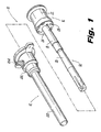
- FIG. 1 illustrates in perspective view the trocar assembly in accordance with the principles of the present disclosure.
- the trocar assembly 10 is intended to be used in laparoscopic surgery where insufflation gases are introduced into the peritoneal cavity to raise the cavity wall away from the internal organs therein.
- Trocar assembly 10 includes a cannula assembly 12 and an obturator assembly 14 which is positionable within the cannula assembly 12.
- obturator assembly refers to the tissue penetrating portion of the trocar assembly 10.
- Obturator assembly 14 includes obturator housing 16, obturator sleeve 18 connected to and extending from the housing 16 and obturator portion 20 which is at least partially disposed within the obturator sleeve 18.
- Obturator housing 16 includes frame or base 22 which is of sufficient size to be grasped by the hands of the user and locking collar 24 mounted to the distal end of the base 22.
- the base 22 includes a plurality of circumferentially disposed resilient tabs 26 which are received within correspondingly dimensioned and positioned apertures 28 defined in the perimeter of the locking collar 24 to effectuate the mounting.
- Other means for mounting base 22 and locking collar 24 are envisioned as well such as with the use of adhesives or the like. It is also contemplated that base 22 and locking collar 24 may be a single unit.
- housing 16 also includes a latch lock arrangement for releasably mounting the obturator assembly 14 to the cannula assembly 12.
- the latch lock arrangement consists of two diametrically opposed latches 30 pivotally mounted to locking collar 24 through the cooperation of integrally formed pivot pins 32 of the latches 30 with internal mounting slots 34 defined in the locking collar 24.
- Latches 30 are biased radially outwardly through latch openings 36 defined in locking collar 24 upon advancement of obturator portion 20 to engage corresponding structure of cannula assembly 12, thus, mounting the obturator assembly 14 to the cannula assembly 12.
- This particular mounting arrangement is described in commonly assigned Serial No. 08/407,342,filed March 20, 1995.
- obturator assembly 14 further includes, from proximal to distal, actuating button 38, obturator return spring 40 and latch collar 42.
- Actuating button 38 includes an internal cylindrical collar portion 44 possessing opposed bayonet-type locking slots 46 as best depicted in FIG. 2.
- latch collar 42 has opposed locking pins 48 extending radially outwardly which are received within locking slots 46 to operatively connect actuating button 38 and latch collar 42 in a manner whereby movement of the actuating button 38 causes corresponding translation of the latch collar 42.
- latch collar 42 has a latch mount 50 which is detachably mounted to the main section 42a of the latch collar 42.
- latch mount 50 includes at least two interior longitudinal rails 52 which receive two longitudinal exterior ribs 54 of the main section 42a as best depicted in FIG. 6.
- Other means for mounting the latch mount 50 to the main section 42a are envisioned as well.
- Latch mount 50 has a locking latch 56 pivotally mounted along its outer surface about pivot pin 58 (FIG 5). Latch 56 extends through side opening 60 of latch mount 50.
- a leaf spring 62 is mounted to latch mount 50 and defines a latch engaging portion 62a which engages the proximal end portion of latch 56 to bias the latch 56 outwardly in a counterclockwise direction with relation to FIG. 5.
- obturator assembly 14 includes obturator shaft 64, protective guard or sleeve 66 coaxially mounted about the obturator shaft 64 and spring retention collar 68.
- Obturator shaft 64 has main shaft portion 64a which extends from within obturator housing 16 and terminates in distal mounting head 70.
- the proximal end portion of obturator shaft 64 possesses a longitudinal bore 72 which terminates in spring abutment head 74 (FIG. 5).
- a shaft biasing spring 76 is at least partially disposed in longitudinal bore 72 of obturator shaft 64 and engages at its first end inner surface 78 of actuating button 38 and at its second end abutment head 74 of shaft 64. Biasing spring 76 normally biases obturator shaft 64 distally.
- Obturator shaft 64 has a resilient pawl 80 which is mounted within a slotted portion 82 of obturator shaft 64 about pin 84. (FIG. 8)
- Pawl 80 has a proximal end 80a which engages inner horizontal shelf 86 of obturator shaft 64 to limit counterclockwise motion of the pawl 82 in relation to FIG. 5.
- Obturator shaft 64 also has distal penetrating member 88 which is mounted to distal mounting head 70 of obturator shaft 64 by the reception of the mounting head 70 within mounting recess 90 defined within the member 88.
- Penetrating member 88 has a pyramidal-shaped penetrating tip 92 dimensioned to penetrate body tissue with minimal force.
- protective guard 66 is mounted for reciprocal longitudinal movement relative to obturator shaft 64 and penetrating member 88 between a fully extended position in which the penetrating tip 92 is fully enclosed by the guard 66 and a retracted position in which the penetrating tip 92 is at least partially exposed.
- a guard biasing spring 94 is disposed within protective guard 66 and is coaxially mounted about obturator shaft 64. Guard biasing spring 94 engages at its first end spring collar 68 and at its second end internal shelf 96 of protective guard 66 and functions in normally biasing the protective guard 66 distally.
- Protective guard 66 defines a constricted proximal portion 66a and an enlarged distal portion 66b to accommodate penetrating member 88.
- the distal portion 66b of protective guard 66 has three equidistally spaced slots 98 and defines a generally triangular or pyramidal cross-section which corresponds generally in dimension to the cross-section of the penetrating tip 92 of penetrating member 88.
- Cannula assembly 12 includes cannula sleeve 200 and cannula housing 202 mounted on one end of the sleeve.
- Sleeve 200 defines a cannula passage in its interior for reception of obturator assembly 14 and may be formed of stainless steel or the like.
- Cannula housing 202 is rigidly secured to the proximal end of sleeve 200 and defines a longitudinal bore for reception and passage of obturator portion 20 of assembly 14.
- Cannula housing 202 further includes an inner peripheral ledge (not shown) at its proximal end which cooperates with latch locks 30 of obturator housing 16 to securely mount the obturator assembly to the cannula assembly 12.
- Cannula housing 202 may further include a seal (not shown) to minimize loss of insufflation gases during introduction and removal of the surgical instrument through the cannula assembly 12.
- a stop clock valve 204 is also provided to permit the passage of insufflation gases through the cannula and into the body cavity.
- trocar assembly 10 is positioned within cannula assembly 12 in the manner depicted in FIG. 4.
- actuating button 38 is distally advanced by depression of the proximal end of the button 38 thereby causing simultaneous distal movement of latch collar 42 and obturator shaft 64.
- "arming" of the trocar assembly 10 is achieved by further advancing actuating button 38 to its distalmost position shown in FIG. 9. During such movement, latch surface 102 of locking latch 56 engages the proximal end face of spring retention collar 68 to cause simultaneous distal movement of the collar 68.
- inner camming fingers 103 of the button 38 traverse the interior surfaces of locking latches 30 to bias the locking ledge 30a of the locking latch 30 radially outwardly.
- the locking ledges 30a lockingly engage an inner peripheral ledge of cannula housing 202 thereby securing the obturator assembly 14 to the cannula assembly 12.
- locking latch 56 is received within opening 104 provided in obturator sleeve 18 whereby latch engaging surface 56a engages locking shelf 105 defined by the opening 104 thereby releasably securing actuating button 38 and obturator shaft 64 in the distalmost "armed” position.
- leaf spring 62 continually biases locking latch 56 into engagement with the shelf 105.
- penetrating tip 88 and the distal portion of protective guard 66 extend beyond cannula sleeve 202 as depicted in FIG. 10.
- Protective guard 66 is biased to the extended position under the influence of compression spring 94.
- proximal movement of obturator shaft 64 is permitted in the "armed" position of actuating button 38 due to the clearance provided between the proximal end face of the obturator shaft 64 and the interior surface 78 of the button 38.
- FIGS. 12 and 13 illustrates obturator shaft 64 in its retracted or proximalmost position.
- mounting latches 30 of locking collar 24 become disengaged from the inner shelf (not shown) of cannula housing 202 thus permitting the removal of obturator assembly 14 from cannula assembly (FIGS. 2 and 3) thereby leaving the cannula assembly within the incision to accept appropriate surgical instrumentation so as to conduct the desired surgery.
- FIGS. 15-17 there is illustrated an alternative embodiment of the present disclosure.
- This embodiment incorporates an identical latch mechanism for releasably securing the obturator in its distal position as described in connection with the embodiment of FIG. 1 and is "armed” and “disarmed” in a similar manner.
- elongated protective guard 66 is replaced with a truncated protective sleeve 122 as shown.
- a coil spring 124 is coaxially mounted about shaft portion 126 of penetrating member 128 and engages the distal face 130 of obturator shaft 132 and the proximal end of protective sleeve 122.
- Coil spring 124 normally biases protective sleeve 122 distally. With obturator shaft 64 distally advanced to its distal "armed" position shown in FIG. 16, application of the obturator against body tissue causes protective sleeve 122 to move proximally thereby exposing the penetrating tip 134 for penetrating action as shown in FIG. 17. Once the counterforce is removed, the protective sleeve 122 returns to its distal extended position under the influence of spring 124.
Description
- The present disclosure relates generally to trocar assemblies for use in endoscopic surgical procedures and, in particular, to a trocar assembly incorporating a mechanism to minimize the possibility of inadvertent injury to viscera and other internal tissue during use. US-A-4 654 030 Moll and EP-A-599 354 US Surgical Corporation disclose trocar assemblies having the technical features of the precharacterizing part of
claim 1 below. - Endoscopic surgical procedures, that is, surgical procedures performed through tubular sleeves or cannulas, have been increasingly accepted as the preferred treatment for ailments traditionally treated via conventional surgical techniques. Initially, endoscopic surgical procedures were primarily diagnostic in nature. More recently, however, as endoscopic technology has advanced, surgeons are performing increasingly complex and innovative surgical procedures using endoscopic principles. In endoscopic procedures, surgery is performed in any hollow viscus of the body through a small incision or through narrow endoscopic tubes (cannulas) inserted through small entrance wounds in the skin. Endoscopic procedures require the surgeon to act on organs, tissues and vessels far removed from the incision, thereby requiring that any instruments to be used in such procedures be sufficient in size and length to permit remote operation.
- Laparoscopic surgery is a type of endoscopic surgery in which the surgical procedures are performed in the interior of the abdomen. In accordance with laparoscopic techniques, the surgical region, e.g., abdominal cavity, is insufflated with a gas such as C02 to raise the cavity wall away from the internal organs therein. Thereafter, a trocar is used to puncture the body cavity. Generally, a trocar includes an obturator having a sharp penetrating tip disposed within a protective tube or sleeve. The trocar is typically used with, or incorporates, a cannula having a cannula sleeve which remains within the incision subsequent to removal of the obturator. The cannula defines a port for the insertion of surgical instruments required to perform the desired surgery. An example of a known trocar is described in commonly assigned U.S. Patent No. 4,601,710 to Moll.
- Recent developments in the design of surgical trocars include the provision of safety mechanisms to ensure that the distal penetrating tip is covered or enclosed once the body cavity has been penetrated, thereby providing an increased level of protection to internal structured from undesired puncture or laceration. Examples of safety trocars are disclosed in U.S. Patent Nos.: 3,030,959 to Grunert; 3,657,812 to Lee; 4,375,815 to Burns; 4,535,773 to Yoon; 4,601,710 to Moll; and 5,116,353 to Green.
- The present invention is defined by
claim 1 below. Dependent claims are directed to optional or preferred features. - The present disclosure is directed to further improvements in the design of safety trocars. In one preferred embodiment, the novel trocar assembly includes a cannula assembly having a cannula housing with a cannula sleeve and an obturator assembly which includes (i) an obturator housing, (ii) an obturator sleeve connected to the obturator housing, (iii) an elongated obturator portion at least partially disposed within the obturator sleeve and having a penetrating distal tip for penetrating tissue, and (iv) a protective guard coaxially mounted about the penetrating tip. The obturator portion is longitudinally moveable between a disarmed position wherein the penetrating tip is contained within the cannula sleeve and an armed position wherein the penetrating tip and at least the distal end portion of the protective guard extend beyond the distal end of the cannula sleeve. The obturator portion is normally biased to the disarmed position.
- Means are provided to retain the obturator portion in the armed position. The preferred retaining means is in the form of a latch mechanism having a latch mounted to the obturator portion and being configured and dimensioned to engage corresponding structure, e.g. a locking shelf of the obturator sleeve, to maintain the obturator portion in the armed position.
- Release means are also provided for releasing the retaining means to permit the obturator portion to return to the disarmed position. The preferred release means includes a pawl mechanism having a pawl which engages and displaces the latch from its engagement with the internal shelf of the obturator sleeve. The release means is actuated upon removal of a counterforce applied to the penetrating tip, i.e., upon entering through the body tissue.
- The protective guard of the obturator is moveable relative to the penetrating tip between an extended position enclosing the penetrating tip and a retracted position exposing the penetrating tip for penetrating action. The protective guard is normally spring biased to the extended position and moves to the retracted position in response to a counterforce exerted by tissue on the protective guard during insertion through the tissue.
- In use of the trocar assembly, the obturator portion is placed in its armed position thereby advancing the penetrating tip and protective guard at least partially beyond the cannula sleeve. Once in the armed position, the obturator portion is retained in said position by the latch mechanism of the retaining means. The penetrating tip is placed against tissue whereby the counterforce exerted by the tissue causes the protective guard to retract to expose the penetrating tip. When the penetrating tip clears the tissue (thus resulting in the removal of the counterforce), the protective guard assumes its normal extended position enclosing the penetrating tip. Concurrently therewith, the removal of the counterforce activates the release means thereby causing the obturator portion to assume its non-deployed position.
- Preferred embodiment(s) of the disclosure are described hereinafter with reference to the drawings wherein:
- FIG. 1 is a perspective view of the trocar assembly of the present disclosure illustrating the obturator assembly and cannula assembly;
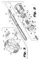
- FIG. 2 is a perspective view with parts separated of the obturator assembly illustrating the obturator housing, the obturator sleeve and the elongated obturator portion disposed within the obturator sleeve;
- FIG. 3 is a perspective view illustrating the locking collar of the obturator housing for releasably mounting the obturator assembly to the cannula assembly;
- FIG. 4 is a side cross-sectional view of the assembled trocar assembly illustrating the obturator portion in the disarmed position;
- FIG. 5 is an enlarged cross-sectional view of the obturator housing and cannula housing illustrating the latch mechanism for releasably retaining the obturator portion in an armed position;
- FIG. 6 is a perspective view with parts separated of the latch collar for mounting the latch of the latch mechanism of FIG. 5;
- FIG. 7 is a perspective view with part separated of the obturator portion of the obturator assembly illustrating the spring retention collar, the guard biasing spring, the protective guard and the obturator shaft;
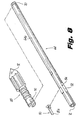
- FIG. 8 is a perspective view with part separated of the obturator shaft and the penetrating tip mounted to the obturator shaft;
- FIG. 9 is a view similar to the view of FIG. 5 illustrating distal advancement of the actuating button to move the obturator portion to the armed position thereof;
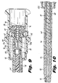
- FIG. 10 is a side cross-sectional view illustrating the obturator portion in the armed position;
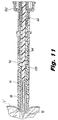
- FIG. 11 is a side cross-sectional view illustrating the obturator portion applied against tissue whereby the protective sleeve moves proximally in response to the counterforce exerted by the tissue to expose the penetrating tip;
- FIG. 12 is a view similar to the view of FIG. 9 illustrating proximal movement of the obturator shaft in response to the counterforce exerted by the tissue on the penetrating tip and the corresponding movement of the latch mechanism;
- FIG. 13 is a view similar to the view of FIG. 12 illustrating the obturator shaft fully retracted and the corresponding arrangement of the latch mechanism;
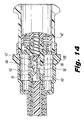
- FIG. 14 is a view similar to the view of FIG. 13 illustrating the advancing movement of the obturator shaft when the penetrating tip clear the tissue and the corresponding release of the latch mechanism;
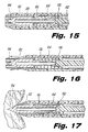
- FIG. 15 is a side cross-sectional view of the distal end of another embodiment of the obturator assembly illustrating a protective guard positioned over the obturator penetrating tip;
- FIG. 16 is a view similar to the view of FIG. 15 illustrating the obturator portion in the armed position with the protective guard and obturator tip extending beyond the obturator and cannula sleeves; and
- FIG. 17 is a view similar to the view of FIG. 16 illustrating the protective guard retracted upon application of the obturator against tissue.
-
- Referring now in specific detail to the drawings, in which like reference numerals identify similar or like components throughout the views, FIG. 1 illustrates in perspective view the trocar assembly in accordance with the principles of the present disclosure. The
trocar assembly 10 is intended to be used in laparoscopic surgery where insufflation gases are introduced into the peritoneal cavity to raise the cavity wall away from the internal organs therein.Trocar assembly 10 includes acannula assembly 12 and an obturator assembly 14 which is positionable within thecannula assembly 12. The term "obturator assembly" as used herein refers to the tissue penetrating portion of thetrocar assembly 10. - Referring now to FIGS. 1 and 2, obturator assembly 14 will be discussed in detail. Obturator assembly 14 includes
obturator housing 16,obturator sleeve 18 connected to and extending from thehousing 16 andobturator portion 20 which is at least partially disposed within theobturator sleeve 18.Obturator housing 16 includes frame orbase 22 which is of sufficient size to be grasped by the hands of the user and lockingcollar 24 mounted to the distal end of thebase 22. In a preferred mounting arrangement ofbase 22 and lockingcollar 24, thebase 22 includes a plurality of circumferentially disposedresilient tabs 26 which are received within correspondingly dimensioned and positionedapertures 28 defined in the perimeter of the lockingcollar 24 to effectuate the mounting. Other means for mountingbase 22 and lockingcollar 24 are envisioned as well such as with the use of adhesives or the like. It is also contemplated thatbase 22 and lockingcollar 24 may be a single unit. - With particular reference to FIGS. 2-3,
housing 16 also includes a latch lock arrangement for releasably mounting the obturator assembly 14 to thecannula assembly 12. The latch lock arrangement consists of two diametrically opposed latches 30 pivotally mounted to lockingcollar 24 through the cooperation of integrally formed pivot pins 32 of thelatches 30 with internal mountingslots 34 defined in thelocking collar 24.Latches 30 are biased radially outwardly throughlatch openings 36 defined in lockingcollar 24 upon advancement ofobturator portion 20 to engage corresponding structure ofcannula assembly 12, thus, mounting the obturator assembly 14 to thecannula assembly 12. This particular mounting arrangement is described in commonly assigned Serial No. 08/407,342,filed March 20, 1995. - Referring now to FIGS. 4-5, in conjunction with FIG.. 2, obturator assembly 14 further includes, from proximal to distal, actuating
button 38,obturator return spring 40 andlatch collar 42.Actuating button 38 includes an internalcylindrical collar portion 44 possessing opposed bayonet-type locking slots 46 as best depicted in FIG. 2. Similarly,latch collar 42 has opposed locking pins 48 extending radially outwardly which are received within lockingslots 46 to operatively connect actuatingbutton 38 andlatch collar 42 in a manner whereby movement of theactuating button 38 causes corresponding translation of thelatch collar 42. - Referring now to FIGS. 2, 5 and 6,
latch collar 42 has alatch mount 50 which is detachably mounted to themain section 42a of thelatch collar 42. In a preferred mounting arrangement, latch mount 50 includes at least two interiorlongitudinal rails 52 which receive two longitudinalexterior ribs 54 of themain section 42a as best depicted in FIG. 6. Other means for mounting thelatch mount 50 to themain section 42a are envisioned as well.Latch mount 50 has a lockinglatch 56 pivotally mounted along its outer surface about pivot pin 58 (FIG 5).Latch 56 extends through side opening 60 oflatch mount 50. Aleaf spring 62 is mounted to latchmount 50 and defines a latch engaging portion 62a which engages the proximal end portion oflatch 56 to bias thelatch 56 outwardly in a counterclockwise direction with relation to FIG. 5. - Referring now to FIGS. 7-8, in conjunction with FIGS. 4-5, obturator assembly 14 includes
obturator shaft 64, protective guard orsleeve 66 coaxially mounted about theobturator shaft 64 andspring retention collar 68.Obturator shaft 64 hasmain shaft portion 64a which extends from withinobturator housing 16 and terminates in distal mountinghead 70. The proximal end portion ofobturator shaft 64 possesses alongitudinal bore 72 which terminates in spring abutment head 74 (FIG. 5). Ashaft biasing spring 76 is at least partially disposed inlongitudinal bore 72 ofobturator shaft 64 and engages at its first endinner surface 78 ofactuating button 38 and at its second end abutment head 74 ofshaft 64. Biasingspring 76 normallybiases obturator shaft 64 distally.Obturator shaft 64 has aresilient pawl 80 which is mounted within a slottedportion 82 ofobturator shaft 64 aboutpin 84. (FIG. 8)Pawl 80 has aproximal end 80a which engages inner horizontal shelf 86 ofobturator shaft 64 to limit counterclockwise motion of thepawl 82 in relation to FIG. 5.Obturator shaft 64 also has distal penetratingmember 88 which is mounted to distal mountinghead 70 ofobturator shaft 64 by the reception of the mountinghead 70 within mountingrecess 90 defined within themember 88. Penetratingmember 88 has a pyramidal-shaped penetratingtip 92 dimensioned to penetrate body tissue with minimal force. - Referring now to FIGS. 4 and 7,
protective guard 66 is mounted for reciprocal longitudinal movement relative toobturator shaft 64 and penetratingmember 88 between a fully extended position in which the penetratingtip 92 is fully enclosed by theguard 66 and a retracted position in which the penetratingtip 92 is at least partially exposed. Aguard biasing spring 94 is disposed withinprotective guard 66 and is coaxially mounted aboutobturator shaft 64.Guard biasing spring 94 engages at its firstend spring collar 68 and at its second end internal shelf 96 ofprotective guard 66 and functions in normally biasing theprotective guard 66 distally.Protective guard 66 defines a constrictedproximal portion 66a and an enlarged distal portion 66b to accommodate penetratingmember 88. The distal portion 66b ofprotective guard 66 has three equidistally spacedslots 98 and defines a generally triangular or pyramidal cross-section which corresponds generally in dimension to the cross-section of the penetratingtip 92 of penetratingmember 88. - Referring again to FIG. 1,
cannula assembly 12 oftrocar assembly 10 will now be described.Cannula assembly 12 includescannula sleeve 200 andcannula housing 202 mounted on one end of the sleeve.Sleeve 200 defines a cannula passage in its interior for reception of obturator assembly 14 and may be formed of stainless steel or the like.Cannula housing 202 is rigidly secured to the proximal end ofsleeve 200 and defines a longitudinal bore for reception and passage ofobturator portion 20 of assembly 14.Cannula housing 202 further includes an inner peripheral ledge (not shown) at its proximal end which cooperates withlatch locks 30 ofobturator housing 16 to securely mount the obturator assembly to thecannula assembly 12.Cannula housing 202 may further include a seal (not shown) to minimize loss of insufflation gases during introduction and removal of the surgical instrument through thecannula assembly 12. Astop clock valve 204 is also provided to permit the passage of insufflation gases through the cannula and into the body cavity. - The operation of
trocar assembly 10 will now be discussed. Obturator assembly 14 is positioned withincannula assembly 12 in the manner depicted in FIG. 4. Referring now to FIG. 5,actuating button 38 is distally advanced by depression of the proximal end of thebutton 38 thereby causing simultaneous distal movement oflatch collar 42 andobturator shaft 64. With reference now to FIGS. 9-10, "arming" of thetrocar assembly 10 is achieved by further advancingactuating button 38 to its distalmost position shown in FIG. 9. During such movement,latch surface 102 of lockinglatch 56 engages the proximal end face ofspring retention collar 68 to cause simultaneous distal movement of thecollar 68. In addition, during advancing movement ofactuating button 38,inner camming fingers 103 of the button 38 (FIG. 2) traverse the interior surfaces of locking latches 30 to bias the lockingledge 30a of the lockinglatch 30 radially outwardly. In the radial outward position, the lockingledges 30a lockingly engage an inner peripheral ledge ofcannula housing 202 thereby securing the obturator assembly 14 to thecannula assembly 12. - Once actuating
button 38 reaches the "armed" position depicted in FIGS. 9-10, lockinglatch 56 is received withinopening 104 provided inobturator sleeve 18 wherebylatch engaging surface 56a engages lockingshelf 105 defined by theopening 104 thereby releasably securingactuating button 38 andobturator shaft 64 in the distalmost "armed" position. It is to be noted thatleaf spring 62 continuallybiases locking latch 56 into engagement with theshelf 105. In the "armed" position ofobturator assembly 12, penetratingtip 88 and the distal portion ofprotective guard 66 extend beyondcannula sleeve 202 as depicted in FIG. 10.Protective guard 66 is biased to the extended position under the influence ofcompression spring 94. - Referring now to FIG. 11, with the
obturator shaft 64 fully extended, the surgeon presses the distal end of the obturator against the body cavity lining "t". The counterforce applied by the tissue causes: 1)protective guard 66 to move proximally against the influence ofguard biasing spring 94 from the extended position depicted in FIG. 10 to the retracted position shown in FIG. 11 thereby exposing the penetratingtip 92 for penetrating action; and 2) the penetratingtip 92 andobturator shaft 64 to move proximally against the influence of shaft biasing spring 76 (FIG. 9). It is to be noted that proximal movement ofobturator shaft 64 is permitted in the "armed" position ofactuating button 38 due to the clearance provided between the proximal end face of theobturator shaft 64 and theinterior surface 78 of thebutton 38. - With reference to FIGS. 12 and 13, as
obturator shaft 64 moves proximally,forward portion 106 ofpawl 80 engages inclinedsurface 108 of lockinglatch 56 and is driven downwardly by thelatch 56 so as to gain clearance thereby. The resilient quality ofpawl 80 permits thepawl 80 to flex downwardly and rotate slightly in a counterclockwise direction upon engagement with lockinglatch 56 as depicted in FIG. 12 to assume the orientation of FIG. 13. FIG. 13 illustratesobturator shaft 64 in its retracted or proximalmost position. - Once the incision is made and as penetrating
tip 92 passes through the body tissue, the counterforce applied against penetratingtip 92 by the body tissue ceases. As a result,protective guard 66 is biased distally under the influence ofguard biasing spring 94 to cover penetratingtip 92. In addition, the absence of the counterforce permitsshaft biasing spring 76 to spring distally to its rest position, thereby biasingobturator shaft 64 distally. With reference to FIG. 14, asobturator shaft 64 moves distally, forward surface 110 ofpawl 80 engagesshelf 112 of lockinglatch 56 and causes thelatch 56 to rotate in a general clockwise direction against the influence oflever spring 62. This clockwise rotation of lockinglatch 56 results in clockwise rotation of rearengaging surface 56a thereby freeing thelatch 56 from its engagement withinternal shelf 105 ofobturator sleeve 18. - As soon as
latch 56 clearsinternal shelf 105, there no longer remains any restraint to the return ofactuator button 38 to its initial position. Thus,actuator button 38 andlatch collar 42 move proximally under the influence ofobturator return spring 40. With reference again to FIG. 5, aslatch collar 42 moves proximally,vertical surface 116 of lockinglatch 56 engages innervertical surface 118 ofobturator shaft 64 thereby driving theobturator shaft 64 proximally. Such movement ofobturator shaft 64 simultaneously corresponds in proximal movement ofprotective sleeve 66 through the engagement of forwardvertical surface 120 of penetrating member 86 withinner shelf 122 of the protective guard 66 (FIG. 4). This proximal movement ofprotective guard 66 also drivesspring retention collar 68 proximally through the interaction ofcompression spring 94 with the distal face of thecollar 68. - In addition, with
actuating button 38 in the proximal inactivated position, mountinglatches 30 of lockingcollar 24 become disengaged from the inner shelf (not shown) ofcannula housing 202 thus permitting the removal of obturator assembly 14 from cannula assembly (FIGS. 2 and 3) thereby leaving the cannula assembly within the incision to accept appropriate surgical instrumentation so as to conduct the desired surgery. - Referring now to FIGS. 15-17, there is illustrated an alternative embodiment of the present disclosure. This embodiment incorporates an identical latch mechanism for releasably securing the obturator in its distal position as described in connection with the embodiment of FIG. 1 and is "armed" and "disarmed" in a similar manner. However, in accordance with this embodiment, elongated
protective guard 66 is replaced with a truncatedprotective sleeve 122 as shown. Acoil spring 124 is coaxially mounted aboutshaft portion 126 of penetratingmember 128 and engages thedistal face 130 ofobturator shaft 132 and the proximal end ofprotective sleeve 122.Coil spring 124 normally biasesprotective sleeve 122 distally. Withobturator shaft 64 distally advanced to its distal "armed" position shown in FIG. 16, application of the obturator against body tissue causesprotective sleeve 122 to move proximally thereby exposing the penetratingtip 134 for penetrating action as shown in FIG. 17. Once the counterforce is removed, theprotective sleeve 122 returns to its distal extended position under the influence ofspring 124. - While the above description contains many specifics, these specifics should not be construed as limitations on the scope of the disclosure, but merely as exemplifications of preferred embodiments thereof. The claims which follow identify embodiments of the invention additional to those described in detail above.
Claims (12)
- A trocar assembly (10), which comprises:and further characterized by:a cannula (12) including a cannula (202) and a cannula sleeve (200) extending form the cannula housing; andan obturator assembly (14) which includes:an obturator housing (22);an elongated obturator portion (20) mounted with respect to the obturator housing, the obturator portion being contained within the cannula sleeve and including proximal and distal ends, and having a penetrating tip (92) associated with the distal end for penetrating tissue, the trocar assembly (10) having a disarmed position wherein the penetrating tip is contained within the cannula sleeve and the trocar assembly having an armed position wherein the penetrating tip at least partially extends beyond the distal end of the cannula sleeve; and characterized in that:the obturator portion (20) is mounted for longitudinal movement, relative to the obturator housing and within the cannula sleeve, between the armed and disarmed positions;retaining means (56, 104) which releasably retains the obturator portion in the armed position;release means (80, 108, 56), which releases the retaining means, to permit the obturator portion to return to the disarmed position, upon actuation by removal of a counterforce applied to the penetrating tip by body tissue, when the penetrating tip has passed through said body tissue; anda protective guard coaxially mounted about the penetrating tip and movable relative to the penetrating tip between an extended position and a retracted position wherein, in the armed position of the obturator portion, the protective guard moves to the retracted position in response to counterforce exerted by tissue on the protective guard during insertion through the tissue and, in doing so, at least partially exposes the penetrating tip for tissue penetration.
- The trocar assembly according to claim 1 including guard biasing means (94) for normally biasing the protective guard to the extended position thereof whereby, upon passing through the tissue, the protective guard is biased by the guard biasing means to the extended position.
- The trocar assembly according to claim 2 wherein the guard biasing means includes a spring member.
- The trocar assembly according to claim 1, 2 or 3 including obturator biasing means (40) for normally biasing the obturator portion to the disarmed position.
- The trocar assembly according to claim 4 wherein the obturator biasing means includes a spring member.
- The trocar assembly according to any one of the preceding claims including an obturator sleeve (18) mounted to the obturator housing and extending distally therefrom.
- The trocar assembly according to claim 6 as dependent on claim 5, wherein the retaining means includes a latch mechanism, the latch mechanism including a latch (56) mounted to the obturator portion and being configured and dimensioned to engage corresponding structure (104) of the obturator sleeve to maintain the obturator portion in the armed position.
- The trocar assembly according to claim 7 wherein the obturator sleeve includes an internal shelf (105) and wherein the latch of the latch mechanism is configured and dimensioned to engage the internal shelf to thereby maintain the obturator shaft in the extended position.
- The trocar assembly according to any one of the preceding claims wherein the obturator portion includes an obturator shaft (64), the penetrating tip being mounted to a distal end portion of the obturator shaft.
- The trocar assembly according to claim 9 wherein the obturator shaft is reciprocally longitudinally movable between proximal and distal positions thereof when the obturator portion is in the armed position and further wherein the obturator shaft is spring-biased (76) to its distal position.
- The trocar assembly according to claim 10 wherein the obturator shaft is adapted to assume its proximal position in response to a counterforce being applied to the penetrating tip and wherein upon removal of the counterforce the obturator shaft moves to its distal position.
- The trocar assembly according to claim 11 as dependent on claim 7, wherein the release means includes a pawl (80) mounted to the obturator shaft and configured and dimensioned to engage the latch upon movement of the obturator shaft distally from its proximal position to its distal position upon removal of the counterforce to thereby release the retaining means and permit the obturator portion to return to the disarmed position thereof.
Applications Claiming Priority (2)
| Application Number | Priority Date | Filing Date | Title |
|---|---|---|---|
| US08/645,885 US5669885A (en) | 1996-05-14 | 1996-05-14 | Trocar assembly with spring-loaded mechanism |
| US645885 | 1996-05-14 |
Publications (2)
| Publication Number | Publication Date |
|---|---|
| EP0807414A1 EP0807414A1 (en) | 1997-11-19 |
| EP0807414B1 true EP0807414B1 (en) | 2004-01-02 |
Family
ID=24590863
Family Applications (1)
| Application Number | Title | Priority Date | Filing Date |
|---|---|---|---|
| EP97106372A Expired - Lifetime EP0807414B1 (en) | 1996-05-14 | 1997-04-17 | Trocar assembly with springloaded mechanism |
Country Status (5)
| Country | Link |
|---|---|
| US (1) | US5669885A (en) |
| EP (1) | EP0807414B1 (en) |
| CA (1) | CA2202840C (en) |
| DE (1) | DE69727006T2 (en) |
| ES (1) | ES2210411T3 (en) |
Cited By (3)
| Publication number | Priority date | Publication date | Assignee | Title |
|---|---|---|---|---|
| US7842014B2 (en) | 2006-03-27 | 2010-11-30 | Aesculap Ag | Surgical sealing element, surgical seal, and surgical sealing system |
| US8137318B2 (en) | 2008-07-09 | 2012-03-20 | Aesculap Ag | Surgical protection device for a surgical sealing element and surgical sealing system |
| US8246586B2 (en) | 2008-07-09 | 2012-08-21 | Aesculap Ag | Surgical sealing element holder for holding a surgical sealing element and surgical sealing system |
Families Citing this family (41)
| Publication number | Priority date | Publication date | Assignee | Title |
|---|---|---|---|---|
| WO1998019610A1 (en) * | 1996-11-05 | 1998-05-14 | Mcguire David A | Device and method for tendon harvesting |
| US5906594A (en) | 1997-01-08 | 1999-05-25 | Symbiosis Corporation | Endoscopic infusion needle having dual distal stops |
| US8080058B2 (en) * | 2003-04-01 | 2011-12-20 | Depuy Mitek, Inc. | Method and apparatus for fixing a graft in a bone tunnel |
| US6113604A (en) * | 1997-01-14 | 2000-09-05 | Ethicon, Inc. | Method and apparatus for fixing a graft in a bone tunnel |
| US6106539A (en) | 1998-04-15 | 2000-08-22 | Neosurg Technologies | Trocar with removable, replaceable tip |
| US6280417B1 (en) | 1999-02-23 | 2001-08-28 | Needberg Technologies, Inc. | Trocar |
| MXPA01013402A (en) | 1999-06-22 | 2004-03-10 | E Blanco Ernesto | Safety trocar with progressive cutting tip guards and gas jet tissue deflector. |
| US6319266B1 (en) * | 2000-03-16 | 2001-11-20 | United States Surgical Corporation | Trocar system and method of use |
| DE60140278D1 (en) * | 2000-08-08 | 2009-12-03 | Tyco Healthcare | Shaped trocar seal |
| US7195642B2 (en) | 2001-03-13 | 2007-03-27 | Mckernan Daniel J | Method and apparatus for fixing a graft in a bone tunnel |
| US6517546B2 (en) | 2001-03-13 | 2003-02-11 | Gregory R. Whittaker | Method and apparatus for fixing a graft in a bone tunnel |
| US7594917B2 (en) * | 2001-03-13 | 2009-09-29 | Ethicon, Inc. | Method and apparatus for fixing a graft in a bone tunnel |
| CA2354462C (en) * | 2001-07-30 | 2008-09-23 | William K. Reilly | Medical line stabilizer |
| US6830578B2 (en) * | 2001-11-26 | 2004-12-14 | Neosurg Technologies, Inc. | Trocar |
| US7044921B2 (en) * | 2003-02-03 | 2006-05-16 | Scimed Life Systems, Inc | Medical device with changeable tip flexibility |
| US6960164B2 (en) * | 2003-08-01 | 2005-11-01 | Neosurg Technologies, Inc. | Obturator tip for a trocar |
| US20050040065A1 (en) * | 2003-08-22 | 2005-02-24 | O'heeron Peter T. | Medical procedure kit |
| US7338494B2 (en) * | 2003-08-19 | 2008-03-04 | Synthes (U.S.A.) | Spring-loaded awl |
| US7320694B2 (en) * | 2004-03-11 | 2008-01-22 | Coopersurgical, Inc. | Obturator tip |
| US20050203467A1 (en) * | 2004-03-15 | 2005-09-15 | O'heeron Peter T. | Trocar seal |
| US20050209608A1 (en) * | 2004-03-22 | 2005-09-22 | O'heeron Peter T | Trocar seal |
| US7419496B2 (en) * | 2004-08-03 | 2008-09-02 | Staudner Rupert A | Trocar with retractable cutting surface |
| US7169129B2 (en) * | 2004-10-21 | 2007-01-30 | Gooden Rodney S | Apparatus and method for performing a tracheotomy |
| US8728037B2 (en) | 2006-04-18 | 2014-05-20 | Ethicon Endo-Surgery, Inc. | Pleated trocar seal |
| US7789861B2 (en) * | 2006-04-18 | 2010-09-07 | Ethicon Endo-Surgery, Inc. | Pleated trocar seal |
| EP1875874B1 (en) * | 2006-07-06 | 2013-02-27 | Covidien LP | Two mode trocar assembly |
| WO2008076340A2 (en) * | 2006-12-15 | 2008-06-26 | Tyco Healthcare Group Lp | Trocar assembly with obturator design |
| US20110040149A1 (en) * | 2007-01-12 | 2011-02-17 | Smith Robert C | Obturator assembly |
| EP2120740A1 (en) * | 2007-02-02 | 2009-11-25 | Synthes GmbH | Tunnel tool for soft tissue |
| US8353819B2 (en) * | 2007-04-11 | 2013-01-15 | Covidien Lp | Endoscopic/laparoscopic introducer sleeve |
| EP2142115B1 (en) * | 2007-04-18 | 2016-08-24 | Covidien LP | Trocar assembly with obturator dissector |
| US8282663B2 (en) | 2007-10-05 | 2012-10-09 | Tyco Healthcare Group Lp | Bladeless obturator for use in a surgical trocar assembly |
| US8002788B2 (en) | 2007-10-05 | 2011-08-23 | Tyco Healthcare Group Lp | Two-mode bladeless trocar assembly |
| US8911463B2 (en) * | 2008-06-10 | 2014-12-16 | Covidien Lp | Bladed/bladeless obturator for use in a surgical trocar assembly |
| US9226774B2 (en) * | 2009-12-17 | 2016-01-05 | Covidien Lp | Visual obturator with tip openings |
| US8979883B2 (en) | 2009-12-17 | 2015-03-17 | Covidien Lp | Obturator tip |
| US8961552B2 (en) | 2010-09-21 | 2015-02-24 | Covidien Lp | Bladeless obturators and bladeless obturator members |
| US9005200B2 (en) | 2010-09-30 | 2015-04-14 | Covidien Lp | Vessel sealing instrument |
| US8617176B2 (en) | 2011-08-24 | 2013-12-31 | Depuy Mitek, Llc | Cross pinning guide devices and methods |
| KR101236416B1 (en) * | 2012-06-05 | 2013-02-22 | (주)메덴 | Abdomen opening apparatus for troca having spring structure |
| WO2017091812A1 (en) * | 2015-11-25 | 2017-06-01 | Talon Medical, LLC | Tissue engagement devices, systems, and methods |
Family Cites Families (25)
| Publication number | Priority date | Publication date | Assignee | Title |
|---|---|---|---|---|
| US1248492A (en) * | 1917-04-10 | 1917-12-04 | A D Haskell | Paracentesis needle or trocar. |
| US1640311A (en) * | 1925-01-13 | 1927-08-23 | Willard C Dawes | Surgical instrument |
| US2623521A (en) * | 1951-03-12 | 1952-12-30 | Rose Shaw | Indicating stylet needle |
| US4094217A (en) * | 1977-06-28 | 1978-06-13 | Borg-Warner Corporation | Safety slitter for thermoplastic sheet |
| US4256119A (en) * | 1979-09-17 | 1981-03-17 | Gauthier Industries, Inc. | Biopsy needle |
| US4527561A (en) * | 1981-03-23 | 1985-07-09 | Becton, Dickinson And Company | Automatic retractable lancet assembly |
| US4535773A (en) * | 1982-03-26 | 1985-08-20 | Inbae Yoon | Safety puncturing instrument and method |
| US4601710B1 (en) * | 1983-08-24 | 1998-05-05 | United States Surgical Corp | Trocar assembly |
| DE3518547C2 (en) * | 1985-05-23 | 1994-04-14 | Angiomed Ag | Hollow needle of a biopsy set |
| US4654030A (en) * | 1986-02-24 | 1987-03-31 | Endotherapeutics | Trocar |
| CA1339851E (en) * | 1986-10-17 | 1998-05-05 | Jack R. Lander | Trocar |
| US4767413A (en) * | 1987-04-20 | 1988-08-30 | Habley Medical Technology Corporation | Dental syringe having an automatically retractable needle |
| US4904242A (en) * | 1987-04-29 | 1990-02-27 | Kulli John C | Phlebotomy set with safety retracting needle |
| US4747831A (en) * | 1987-04-29 | 1988-05-31 | Phase Medical, Inc. | Cannula insertion set with safety retracting needle |
| US4874382A (en) * | 1987-10-15 | 1989-10-17 | Servetus Partnership | Safety syringe |
| US4813426A (en) * | 1987-11-09 | 1989-03-21 | Habley Medical Technology Corporation | Shielded safety syringe having a retractable needle |
| GB8816033D0 (en) * | 1988-07-06 | 1988-08-10 | Ethicon Inc | Improved safety trocar |
| US4946446A (en) * | 1989-06-14 | 1990-08-07 | Vadher Dinesh L | Retractable needle |
| US5046508A (en) * | 1989-12-19 | 1991-09-10 | Jonathan Weissler | Syringe with retractable needle |
| US4973316A (en) * | 1990-01-16 | 1990-11-27 | Dysarz Edward D | One handed retractable safety syringe |
| US5116353B1 (en) * | 1990-10-05 | 1996-09-10 | Digital Voice Systems Inc | Safety trocar |
| DE4243809C2 (en) * | 1992-12-23 | 1995-06-08 | Viktor Dr Med Grablowitz | Security trocar |
| US5462532A (en) * | 1993-03-17 | 1995-10-31 | Origin Medsystems, Inc. | Trocar with safety sensing sleeve |
| EP0705077B1 (en) * | 1993-05-28 | 1998-04-08 | Origin Medsystems, Inc. | Retracting tip trocar with plunger sensor |
| US5522833A (en) * | 1994-08-29 | 1996-06-04 | Ethicon Endo-Surgery, Inc. | Retractable obturator for a trocar |
-
1996
- 1996-05-14 US US08/645,885 patent/US5669885A/en not_active Expired - Lifetime
-
1997
- 1997-04-16 CA CA002202840A patent/CA2202840C/en not_active Expired - Fee Related
- 1997-04-17 ES ES97106372T patent/ES2210411T3/en not_active Expired - Lifetime
- 1997-04-17 EP EP97106372A patent/EP0807414B1/en not_active Expired - Lifetime
- 1997-04-17 DE DE69727006T patent/DE69727006T2/en not_active Expired - Lifetime
Cited By (4)
| Publication number | Priority date | Publication date | Assignee | Title |
|---|---|---|---|---|
| US7842014B2 (en) | 2006-03-27 | 2010-11-30 | Aesculap Ag | Surgical sealing element, surgical seal, and surgical sealing system |
| US8137318B2 (en) | 2008-07-09 | 2012-03-20 | Aesculap Ag | Surgical protection device for a surgical sealing element and surgical sealing system |
| US8246586B2 (en) | 2008-07-09 | 2012-08-21 | Aesculap Ag | Surgical sealing element holder for holding a surgical sealing element and surgical sealing system |
| US8696636B2 (en) | 2008-07-09 | 2014-04-15 | Aesculap Ag | Surgical sealing element holder for holding a surgical sealing element and surgical sealing system |
Also Published As
| Publication number | Publication date |
|---|---|
| EP0807414A1 (en) | 1997-11-19 |
| DE69727006D1 (en) | 2004-02-05 |
| CA2202840C (en) | 2006-07-04 |
| DE69727006T2 (en) | 2004-11-25 |
| US5669885A (en) | 1997-09-23 |
| ES2210411T3 (en) | 2004-07-01 |
| CA2202840A1 (en) | 1997-11-14 |
Similar Documents
| Publication | Publication Date | Title |
|---|---|---|
| EP0807414B1 (en) | Trocar assembly with springloaded mechanism | |
| US5569289A (en) | Safety penetrating instrument with penetrating member and cannula moving during penetration and triggered safety member protusion | |
| US5772660A (en) | Trocar assembly with electrocautery penetrating tip | |
| EP2044896B1 (en) | Visual obturator | |
| CA2105321C (en) | Safety trocar with locking handles | |
| US5584848A (en) | Safety penetrating instrument with penetrating member, safety member and cannula moving during penetration and triggered safety member protrusion | |
| US5346459A (en) | Trocar | |
| US5295993A (en) | Safety trocar | |
| EP0617924B1 (en) | Trocar safety shield locking mechanism | |
| US5776156A (en) | Endoscopic cutting instrument | |
| US5324268A (en) | Trocar with safety shield | |
| US6017356A (en) | Method for using a trocar for penetration and skin incision | |
| AU781610B2 (en) | Trocar with reinforced obturator shaft | |
| US5607439A (en) | Safety penetrating instrument with penetrating member moving during penetration and triggered safety member protrusion | |
| US5843115A (en) | Trocar insertion device | |
| US5573545A (en) | Safety penetrating instrument with safety member and cannula moving during penetration and triggered cannula and/or safety member protrusion | |
| AU701798B2 (en) | Safety penetrating instrument with penetrating member and safety member moving during penetration and triggered safety member protrusion | |
| US6280417B1 (en) | Trocar | |
| US5591189A (en) | Safety penetrating instrument with safety member moving during penetration and triggered safety member protrusion | |
| EP1900333B1 (en) | Molded trocar latch |
Legal Events
| Date | Code | Title | Description |
|---|---|---|---|
| PUAI | Public reference made under article 153(3) epc to a published international application that has entered the european phase |
Free format text: ORIGINAL CODE: 0009012 |
|
| AK | Designated contracting states |
Kind code of ref document: A1 Designated state(s): DE ES FR GB IT |
|
| 17P | Request for examination filed |
Effective date: 19980318 |
|
| 17Q | First examination report despatched |
Effective date: 20020208 |
|
| GRAP | Despatch of communication of intention to grant a patent |
Free format text: ORIGINAL CODE: EPIDOSNIGR1 |
|
| GRAS | Grant fee paid |
Free format text: ORIGINAL CODE: EPIDOSNIGR3 |
|
| GRAA | (expected) grant |
Free format text: ORIGINAL CODE: 0009210 |
|
| AK | Designated contracting states |
Kind code of ref document: B1 Designated state(s): DE ES FR GB IT |
|
| REG | Reference to a national code |
Ref country code: GB Ref legal event code: FG4D |
|
| REF | Corresponds to: |
Ref document number: 69727006 Country of ref document: DE Date of ref document: 20040205 Kind code of ref document: P |
|
| REG | Reference to a national code |
Ref country code: ES Ref legal event code: FG2A Ref document number: 2210411 Country of ref document: ES Kind code of ref document: T3 |
|
| ET | Fr: translation filed | ||
| PLBE | No opposition filed within time limit |
Free format text: ORIGINAL CODE: 0009261 |
|
| STAA | Information on the status of an ep patent application or granted ep patent |
Free format text: STATUS: NO OPPOSITION FILED WITHIN TIME LIMIT |
|
| 26N | No opposition filed |
Effective date: 20041005 |
|
| PGFP | Annual fee paid to national office [announced via postgrant information from national office to epo] |
Ref country code: ES Payment date: 20120426 Year of fee payment: 16 |
|
| PGFP | Annual fee paid to national office [announced via postgrant information from national office to epo] |
Ref country code: IT Payment date: 20130423 Year of fee payment: 17 |
|
| PGFP | Annual fee paid to national office [announced via postgrant information from national office to epo] |
Ref country code: GB Payment date: 20140428 Year of fee payment: 18 |
|
| PGFP | Annual fee paid to national office [announced via postgrant information from national office to epo] |
Ref country code: DE Payment date: 20140429 Year of fee payment: 18 Ref country code: FR Payment date: 20140417 Year of fee payment: 18 |
|
| PG25 | Lapsed in a contracting state [announced via postgrant information from national office to epo] |
Ref country code: IT Free format text: LAPSE BECAUSE OF NON-PAYMENT OF DUE FEES Effective date: 20140417 |
|
| REG | Reference to a national code |
Ref country code: ES Ref legal event code: FD2A Effective date: 20150527 |
|
| PG25 | Lapsed in a contracting state [announced via postgrant information from national office to epo] |
Ref country code: ES Free format text: LAPSE BECAUSE OF NON-PAYMENT OF DUE FEES Effective date: 20140418 |
|
| REG | Reference to a national code |
Ref country code: DE Ref legal event code: R119 Ref document number: 69727006 Country of ref document: DE |
|
| GBPC | Gb: european patent ceased through non-payment of renewal fee |
Effective date: 20150417 |
|
| PG25 | Lapsed in a contracting state [announced via postgrant information from national office to epo] |
Ref country code: GB Free format text: LAPSE BECAUSE OF NON-PAYMENT OF DUE FEES Effective date: 20150417 Ref country code: DE Free format text: LAPSE BECAUSE OF NON-PAYMENT OF DUE FEES Effective date: 20151103 |
|
| REG | Reference to a national code |
Ref country code: FR Ref legal event code: ST Effective date: 20151231 |
|
| PG25 | Lapsed in a contracting state [announced via postgrant information from national office to epo] |
Ref country code: FR Free format text: LAPSE BECAUSE OF NON-PAYMENT OF DUE FEES Effective date: 20150430 |